JP2007322451A - Microscope - Google Patents
Microscope Download PDFInfo
- Publication number
- JP2007322451A JP2007322451A JP2006149171A JP2006149171A JP2007322451A JP 2007322451 A JP2007322451 A JP 2007322451A JP 2006149171 A JP2006149171 A JP 2006149171A JP 2006149171 A JP2006149171 A JP 2006149171A JP 2007322451 A JP2007322451 A JP 2007322451A
- Authority
- JP
- Japan
- Prior art keywords
- optical system
- aperture
- light
- objective
- microscope
- Prior art date
- Legal status (The legal status is an assumption and is not a legal conclusion. Google has not performed a legal analysis and makes no representation as to the accuracy of the status listed.)
- Granted
Links
Images


Landscapes
- Microscoopes, Condenser (AREA)
Abstract
【課題】空間分解能を連続的に変更できる顕微装置を提供すること。
【解決手段】顕微装置10は、被測定物20からの光を集光する対物光学系12と、対物光学系12によって集光した光のうち被測定物20の特定部位の光のみを通過するアパーチャ14と、アパーチャ14を通過した光を受光する光検出器16と、対物光学系12によって集光した被測定物20像をアパーチャ14面に結像する結像光学系18と、を備えており、結像光学系18が焦点距離可変なズーム光学系で構成されている。
【選択図】図1A microscope device capable of continuously changing spatial resolution is provided.
A microscope apparatus 10 includes an objective optical system 12 that condenses light from a measurement object 20, and passes only light at a specific part of the measurement object 20 out of the light collected by the objective optical system 12. An aperture 14, a photodetector 16 that receives light that has passed through the aperture 14, and an imaging optical system 18 that forms an image of the object 20 to be measured collected by the objective optical system 12 on the surface of the aperture 14. The imaging optical system 18 is composed of a zoom optical system having a variable focal length.
[Selection] Figure 1
Description
本発明は、赤外顕微鏡、ラマン顕微鏡等の顕微装置、特にその空間分解能の変更機構の改良に関する。 The present invention relates to a microscope such as an infrared microscope and a Raman microscope, and more particularly to an improvement of a mechanism for changing the spatial resolution.
例えば、固定表面に付着した有機物などの分子構造などを調べるため、赤外顕微鏡、ラマン顕微鏡等の各種顕微装置が用いられる。このような顕微装置では被測定物に光を照射し、対物光学系によって被測定物上の特定微小部位からの光を採取し、スペクトルの測定を行う。さらに、所定の空間分解能を達成するため、光路上にアパーチャを設けて、対物光学系によって採取した光のうち、特定微小部位以外の他の部分からの光をカットしている(例えば、特許文献1参照)。こうすることで、測定したい特定微小部位からの光のみがアパーチャを通過し、その光が光検出器で検出される。
従来の顕微装置で空間分解能、つまり測定したい微小部位の範囲の大きさ、の変更は、アパーチャの径を変えることで行なっていた。しかし、この方式では、空間分解能の変更は段階的にしか変更することができないという問題があった。また、アパーチャの径を変更する際に、アパーチャの位置がずれてしまうといった位置再現性の問題もあった。
本発明は上記課題に鑑みなされたものであり、その目的は空間分解能を連続的に変更できる顕微装置を提供することにある。
In the conventional microscope, the spatial resolution, that is, the size of the range of the minute part to be measured is changed by changing the diameter of the aperture. However, this method has a problem that the spatial resolution can be changed only in stages. Also, there has been a problem of position reproducibility that the position of the aperture is shifted when the diameter of the aperture is changed.
The present invention has been made in view of the above problems, and an object of the present invention is to provide a microscope that can continuously change the spatial resolution.
上記目的を達成するため、本発明にかかる顕微装置は、被測定物からの光を集光する対物光学系と、該対物光学系によって集光した光のうち被測定物の特定部位の光のみを通過するアパーチャと、前記アパーチャを通過した光を受光する光検出器と、前記対物光学系とアパーチャの間の光路上に設置され、対物光学系によって集光した被測定物像を前記アパーチャ面に結像する結像光学系と、を備え、前記結像光学系は焦点距離可変なズーム光学系で構成されたことを特徴とする。 In order to achieve the above object, a microscope apparatus according to the present invention includes an objective optical system that condenses light from an object to be measured, and only light at a specific part of the object to be measured among the light collected by the objective optical system. An aperture that passes through the aperture, a photodetector that receives the light that has passed through the aperture, and an object surface that is installed on the optical path between the objective optical system and the aperture and is collected by the objective optical system. An image forming optical system for forming an image, and the image forming optical system comprises a zoom optical system having a variable focal length.
上記の顕微装置において、前記アパーチャと前記光検出器の間の光路上に設置される分光器と、前記アパーチャを通過した光を前記分光器へ導入する入射光学系と、
を備え、前記入射光学系が焦点位置可変なズーム光学系で構成されることが好適である。
上記の顕微装置において、前記アパーチャと前記入射光学系との間の光路上に設置され、前記対物光学系、結像光学系、アパーチャを通過した光以外の別光路からの光を前記分光器に導入する光路切替え手段を備えることが好適である。
In the above microscope apparatus, a spectroscope installed on an optical path between the aperture and the photodetector, an incident optical system for introducing light that has passed through the aperture into the spectroscope,
It is preferable that the incident optical system is a zoom optical system having a variable focal position.
In the above microscope apparatus, the light from another optical path other than the light passing through the objective optical system, the imaging optical system, and the aperture is placed on the optical path between the aperture and the incident optical system to the spectrometer. It is preferable to provide an optical path switching means to be introduced.
本発明にかかる顕微装置によれば、対物光学系によって集光した光をアパーチャへ結像する結像光学系がズーム光学系で構成されているため、空間分解能を連続的に変更することができる。 According to the microscope according to the present invention, since the imaging optical system that forms an image of the light collected by the objective optical system on the aperture is composed of the zoom optical system, the spatial resolution can be continuously changed. .
以下に図面を参照して本発明の好適な実施形態について説明する。
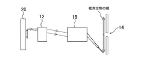
図1は、本発明の実施形態にかかる顕微装置の概略構成図である。図1の顕微装置10は、対物レンズ12(対物光学系)と、アパーチャ14と、光検出器16と、対物レンズ12とアパーチャ14の間の光路上に設置された結像光学系18と、を備える。被測定物20からの光は対物レンズ12によって集光され、結像光学系18へと送られる。結像光学系18は対物レンズ12によって採取した被測定物像をアパーチャ14面に結像する。アパーチャ14では、測定したい特定部位の光のみを通過し、その他の部分からの光を遮断する。そして、アパーチャ14を通過した光は光検出器16によって検出される。
Preferred embodiments of the present invention will be described below with reference to the drawings.
FIG. 1 is a schematic configuration diagram of a microscope apparatus according to an embodiment of the present invention. 1 includes an objective lens 12 (objective optical system), an
ここで、結像光学系18はズーム光学系として構成されている。ズーム光学系とは、複数のレンズによって構成され、結像位置を同一面に保ったまま光学系全体での焦点距離を連続的に変化させることができる光学系であり、像の横倍率を自在に変更できる。
Here, the imaging
以下に図2A、図2Bを参照して、本実施形態の顕微装置における空間分解能の変更機構について説明する。図2A、2Bは、それぞれ異なる空間分解能で被測定物の特定部位を観察している状態を示している。図に示されたように、被測定物の特定部位(図で矢印で示した範囲)の像は、結像光学系18によって所定の倍率でアパーチャ14面に結像される。アパーチャ14面に結像された像(図で矢印で示した部分)のうち、アパーチャ14の径に対応した部分のみがアパーチャ14を通過する。このため、大きな倍率でアパーチャ14面に像を結像した場合(図2A)と、小さな倍率で像を結像した場合(図2B)とを比べると、図2Aの方が図2Bよりもアパーチャ14によって制限される範囲が大きく、より微小な範囲を測定していることになる。
A mechanism for changing the spatial resolution in the microscope according to the present embodiment will be described below with reference to FIGS. 2A and 2B. 2A and 2B show a state where a specific part of the object to be measured is observed with different spatial resolutions. As shown in the figure, an image of a specific part of the object to be measured (a range indicated by an arrow in the figure) is formed on the surface of the
このように、本実施形態の顕微装置10によれば、アパーチャ14を通過し得る被測定物20の特定部位の範囲の大きさを連続的に変更でき、連続的な空間分解能の変更が達成できる。また、アパーチャ14を可動式にする必要がないため、位置再現性の問題もない。
さらに、アパーチャ14の径自体を変更する機構と組み合わせれば、空間分解能のよりきめ細やかな設定もできる。
As described above, according to the microscope apparatus 10 of the present embodiment, the size of the range of the specific part of the
In addition, when combined with a mechanism for changing the diameter of the
また、顕微装置において分光測定を行う際、分光器のスループットを上げるため、分光器の開口角に合わせて、分光器へ光を導入する入射光学系を設定(Fマッチング)する必要がある。 Further, when performing spectroscopic measurement in the microscope, it is necessary to set (F matching) an incident optical system for introducing light into the spectroscope in accordance with the aperture angle of the spectroscope in order to increase the throughput of the spectroscope.
本実施形態の顕微装置には好適にFマッチングを行なう機構も設けられており、図1を再び参照して、本実施形態にかかる顕微装置における、分光器のFマッチング機構を説明する。図1の偏光分光器10はさらに、アパーチャ14と光検出器16の間に設置される分光器22と、集光光学系24と、入射光学系26と、を備える。アパーチャ14を通過した光は集光光学系24によって集光され、入射光学系26へ送られる。入射光学系26は集光レンズ26からの光を分光器22へ導入する。ここで、集光光学系24、入射光学系26は、それぞれズーム光学系で構成されている。
The microscope apparatus of the present embodiment is also provided with a mechanism for suitably performing F matching. With reference to FIG. 1 again, the F matching mechanism of the spectrometer in the microscope apparatus according to the present embodiment will be described. The polarization spectrometer 10 shown in FIG. 1 further includes a
図3A、3Bに示すように、集光光学系24はズーム光学系で構成されており、測定時の対物光学系12および結像光学系18の倍率に応じて焦点距離を変更する。つまり、アパーチャ14から出射する光の広がり角は対物光学系12および結像光学系18の倍率によって異なるため、集光光学系24は焦点距離を変更することで効率的にアパーチャ14からの出射光を集光する。さらに、入射光学系26もズーム光学系で構成されており、集光光学系24から出射した光束の大きさに応じて焦点距離を変更し、集光光学系24のF値を分光器22のF値に合うように調整することができる。このように、本実施形態の顕微装置によれば、分光器のFマッチングを容易に行なうことができる。
As shown in FIGS. 3A and 3B, the condensing
また、顕微装置10は、アパーチャ14と入射光学系26との間の光路上に設置された光路切替え手段28を備えることも好適である。光路切換え手段28は、光路上へ挿入および光路上から退避できる移動可能なミラー30によって構成されている。通常、ミラー30は図1に示すように集光光学系24と入射光学系26との間の光路上から退避しており、対物レンズ12、結像光学系18、アパーチャ14、を通った光が分光器22へと導入される。一方、対物レンズ12、結像光学系18、アパーチャ14、を通った光以外の外部光(例えば、 )を分光器22へ導入したい場合、図4に示すように、ミラー30が光路上へ挿入され、外部光が分光器22へ導入される。なお、図4に示すような外部光を分光器に取り込む場合においても、入射光学系26は外部光の瞳径に応じて焦点距離を変更し、分光器のFマッチングを行なうことができる。
It is also preferable that the microscope apparatus 10 includes an optical
10 顕微装置
12 対物光学系
14 アパーチャ
16 光検出器
18 結像光学系
20 被測定物
22 分光器
24 集光光学系
26 入射光学系
28 光路切換え手段
DESCRIPTION OF SYMBOLS 10
Claims (3)
該対物光学系によって集光した光のうち被測定物の特定部位の光のみを通過するアパーチャと、
前記アパーチャを通過した光を受光する光検出器と、
前記対物光学系とアパーチャの間の光路上に設置され、対物光学系によって集光した被測定物像を前記アパーチャ面に結像する結像光学系と、
を備え、
前記結像光学系は焦点距離可変なズーム光学系で構成されたことを特徴とする顕微装置。 An objective optical system that collects light from the object to be measured;
An aperture that passes only light of a specific part of the object to be measured out of the light collected by the objective optical system;
A photodetector for receiving light that has passed through the aperture;
An imaging optical system that is installed on an optical path between the objective optical system and the aperture, and forms an image of an object to be measured collected by the objective optical system on the aperture surface;
With
2. A microscope apparatus according to claim 1, wherein the imaging optical system comprises a zoom optical system having a variable focal length.
前記アパーチャと前記光検出器の間の光路上に設置される分光器と、
前記アパーチャを通過した光を前記分光器へ導入する入射光学系と、
を備え、
前記入射光学系が焦点位置可変なズーム光学系で構成されたことを特徴とする顕微装置。 The microscopic device according to claim 1, wherein
A spectroscope installed on an optical path between the aperture and the photodetector;
An incident optical system for introducing light that has passed through the aperture into the spectrometer;
With
2. A microscope apparatus according to claim 1, wherein the incident optical system comprises a zoom optical system having a variable focal position.
前記アパーチャと前記入射光学系との間の光路上に設置され、前記対物光学系、結像光学系、アパーチャを通過した光以外の別光路からの光を前記分光器に導入する光路切替え手段を備えたことを特徴とする顕微装置。 The microscope according to claim 2,
An optical path switching unit that is installed on an optical path between the aperture and the incident optical system, and introduces light from another optical path other than the light that has passed through the objective optical system, the imaging optical system, and the aperture into the spectrometer. A microscopic device characterized by comprising.
Priority Applications (1)
| Application Number | Priority Date | Filing Date | Title |
|---|---|---|---|
| JP2006149171A JP4928836B2 (en) | 2006-05-30 | 2006-05-30 | Microscope |
Applications Claiming Priority (1)
| Application Number | Priority Date | Filing Date | Title |
|---|---|---|---|
| JP2006149171A JP4928836B2 (en) | 2006-05-30 | 2006-05-30 | Microscope |
Publications (2)
| Publication Number | Publication Date |
|---|---|
| JP2007322451A true JP2007322451A (en) | 2007-12-13 |
| JP4928836B2 JP4928836B2 (en) | 2012-05-09 |
Family
ID=38855369
Family Applications (1)
| Application Number | Title | Priority Date | Filing Date |
|---|---|---|---|
| JP2006149171A Expired - Fee Related JP4928836B2 (en) | 2006-05-30 | 2006-05-30 | Microscope |
Country Status (1)
| Country | Link |
|---|---|
| JP (1) | JP4928836B2 (en) |
Cited By (1)
| Publication number | Priority date | Publication date | Assignee | Title |
|---|---|---|---|---|
| JP2013506150A (en) * | 2009-09-24 | 2013-02-21 | カール ツァイス マイクロスコピー ゲーエムベーハー | Microscope using light sheet |
Citations (3)
| Publication number | Priority date | Publication date | Assignee | Title |
|---|---|---|---|---|
| JPH09230245A (en) * | 1996-02-20 | 1997-09-05 | Olympus Optical Co Ltd | Confocal microscope |
| JP2001506836A (en) * | 1996-12-24 | 2001-05-22 | ライカ ミクロジュステムス ハイデルベルク ゲーエムベーハー | TV camera |
| JP2006039132A (en) * | 2004-07-26 | 2006-02-09 | Olympus Corp | Laser scanning type observation device |
-
2006
- 2006-05-30 JP JP2006149171A patent/JP4928836B2/en not_active Expired - Fee Related
Patent Citations (3)
| Publication number | Priority date | Publication date | Assignee | Title |
|---|---|---|---|---|
| JPH09230245A (en) * | 1996-02-20 | 1997-09-05 | Olympus Optical Co Ltd | Confocal microscope |
| JP2001506836A (en) * | 1996-12-24 | 2001-05-22 | ライカ ミクロジュステムス ハイデルベルク ゲーエムベーハー | TV camera |
| JP2006039132A (en) * | 2004-07-26 | 2006-02-09 | Olympus Corp | Laser scanning type observation device |
Cited By (3)
| Publication number | Priority date | Publication date | Assignee | Title |
|---|---|---|---|---|
| JP2013506150A (en) * | 2009-09-24 | 2013-02-21 | カール ツァイス マイクロスコピー ゲーエムベーハー | Microscope using light sheet |
| US9110301B2 (en) | 2009-09-24 | 2015-08-18 | Carl Zeiss Microscopy Gmbh | Microscope with a sheet of light |
| US9500849B2 (en) | 2009-09-24 | 2016-11-22 | Carl Zeiss Microscopy Gmbh | Microscope with a light sheet |
Also Published As
| Publication number | Publication date |
|---|---|
| JP4928836B2 (en) | 2012-05-09 |
Similar Documents
| Publication | Publication Date | Title |
|---|---|---|
| TWI754086B (en) | Overlay metrology using multiple parameter configurations | |
| US9976966B2 (en) | Defect inspection method and its device | |
| KR20190089164A (en) | High-throughput, high-resolution optics for reflective and transmissive nanophoton devices | |
| JP5913964B2 (en) | Spectral detection apparatus and confocal microscope equipped with the same | |
| WO2010004720A1 (en) | Microspectroscope | |
| KR102573338B1 (en) | Microscopy System for Structure and Defect Inspection of EUV Lithography Photomasks | |
| JP2005121479A (en) | Confocal microspectroscope | |
| JP2012504242A (en) | Spectral imaging microscopy | |
| US7408636B2 (en) | Method and apparatus for dark field chemical imaging | |
| JP7246073B2 (en) | Microspectroscopic device with position correction function | |
| JP6067083B2 (en) | Defect inspection method and apparatus | |
| JP2004354937A (en) | Laser microscope | |
| US20180209915A1 (en) | Asymmetrical magnification inspection system and illumination module | |
| JP4140490B2 (en) | X-ray analyzer and its focusing device | |
| JP4928836B2 (en) | Microscope | |
| JP5429698B2 (en) | Spectroscopic analyzer for microscope and spectroscopic analysis method of spectroscopic analyzer for microscope | |
| JP2018194634A (en) | Light field microscope | |
| JP2007033381A (en) | Optical inspection apparatus and its lighting method | |
| JP2007071646A (en) | Cathode luminescence detection device | |
| KR20170141943A (en) | Rapid optical inspection method of semiconductor | |
| JP2006047270A (en) | Tunable monochromatic light source | |
| JP2005181124A (en) | Spectrum detection device | |
| JP2018128326A (en) | Optical spectrum measuring apparatus and optical spectrum measuring method | |
| JP2017151373A (en) | Infrared microscope and infrared microscope system | |
| JP2007264322A (en) | Infrared microscope |
Legal Events
| Date | Code | Title | Description |
|---|---|---|---|
| A621 | Written request for application examination |
Free format text: JAPANESE INTERMEDIATE CODE: A621 Effective date: 20080222 |
|
| A977 | Report on retrieval |
Free format text: JAPANESE INTERMEDIATE CODE: A971007 Effective date: 20110401 |
|
| A131 | Notification of reasons for refusal |
Free format text: JAPANESE INTERMEDIATE CODE: A131 Effective date: 20110426 |
|
| A521 | Request for written amendment filed |
Free format text: JAPANESE INTERMEDIATE CODE: A523 Effective date: 20110620 |
|
| TRDD | Decision of grant or rejection written | ||
| A01 | Written decision to grant a patent or to grant a registration (utility model) |
Free format text: JAPANESE INTERMEDIATE CODE: A01 Effective date: 20120207 |
|
| A01 | Written decision to grant a patent or to grant a registration (utility model) |
Free format text: JAPANESE INTERMEDIATE CODE: A01 |
|
| A61 | First payment of annual fees (during grant procedure) |
Free format text: JAPANESE INTERMEDIATE CODE: A61 Effective date: 20120213 |
|
| FPAY | Renewal fee payment (event date is renewal date of database) |
Free format text: PAYMENT UNTIL: 20150217 Year of fee payment: 3 |
|
| R150 | Certificate of patent or registration of utility model |
Ref document number: 4928836 Country of ref document: JP Free format text: JAPANESE INTERMEDIATE CODE: R150 Free format text: JAPANESE INTERMEDIATE CODE: R150 |
|
| R250 | Receipt of annual fees |
Free format text: JAPANESE INTERMEDIATE CODE: R250 |
|
| R250 | Receipt of annual fees |
Free format text: JAPANESE INTERMEDIATE CODE: R250 |
|
| R250 | Receipt of annual fees |
Free format text: JAPANESE INTERMEDIATE CODE: R250 |
|
| R250 | Receipt of annual fees |
Free format text: JAPANESE INTERMEDIATE CODE: R250 |
|
| R250 | Receipt of annual fees |
Free format text: JAPANESE INTERMEDIATE CODE: R250 |
|
| R250 | Receipt of annual fees |
Free format text: JAPANESE INTERMEDIATE CODE: R250 |
|
| R250 | Receipt of annual fees |
Free format text: JAPANESE INTERMEDIATE CODE: R250 |
|
| R250 | Receipt of annual fees |
Free format text: JAPANESE INTERMEDIATE CODE: R250 |
|
| R250 | Receipt of annual fees |
Free format text: JAPANESE INTERMEDIATE CODE: R250 |
|
| R250 | Receipt of annual fees |
Free format text: JAPANESE INTERMEDIATE CODE: R250 |
|
| LAPS | Cancellation because of no payment of annual fees |