JP2007313097A - Game machine - Google Patents
Game machine Download PDFInfo
- Publication number
- JP2007313097A JP2007313097A JP2006146939A JP2006146939A JP2007313097A JP 2007313097 A JP2007313097 A JP 2007313097A JP 2006146939 A JP2006146939 A JP 2006146939A JP 2006146939 A JP2006146939 A JP 2006146939A JP 2007313097 A JP2007313097 A JP 2007313097A
- Authority
- JP
- Japan
- Prior art keywords
- combination
- display
- symbol
- special
- winning combination
- Prior art date
- Legal status (The legal status is an assumption and is not a legal conclusion. Google has not performed a legal analysis and makes no representation as to the accuracy of the status listed.)
- Pending
Links
- 230000000694 effects Effects 0.000 claims abstract description 80
- PZTQVMXMKVTIRC-UHFFFAOYSA-L chembl2028348 Chemical compound [Ca+2].[O-]S(=O)(=O)C1=CC(C)=CC=C1N=NC1=C(O)C(C([O-])=O)=CC2=CC=CC=C12 PZTQVMXMKVTIRC-UHFFFAOYSA-L 0.000 claims abstract description 8
- 238000003860 storage Methods 0.000 claims description 112
- 238000001514 detection method Methods 0.000 claims description 18
- 230000002093 peripheral effect Effects 0.000 claims description 8
- 238000000605 extraction Methods 0.000 claims description 2
- 239000004973 liquid crystal related substance Substances 0.000 abstract description 60
- 238000000034 method Methods 0.000 description 117
- 230000008569 process Effects 0.000 description 117
- 230000008859 change Effects 0.000 description 66
- 238000004519 manufacturing process Methods 0.000 description 42
- 238000012545 processing Methods 0.000 description 21
- 238000003780 insertion Methods 0.000 description 20
- 230000037431 insertion Effects 0.000 description 20
- 238000003825 pressing Methods 0.000 description 11
- 241000167854 Bourreria succulenta Species 0.000 description 8
- 241000219109 Citrullus Species 0.000 description 8
- 235000012828 Citrullus lanatus var citroides Nutrition 0.000 description 8
- 235000019693 cherries Nutrition 0.000 description 8
- 239000010408 film Substances 0.000 description 6
- 238000012544 monitoring process Methods 0.000 description 6
- 238000005070 sampling Methods 0.000 description 5
- 230000008901 benefit Effects 0.000 description 4
- 230000006870 function Effects 0.000 description 4
- 239000011521 glass Substances 0.000 description 4
- 238000004891 communication Methods 0.000 description 3
- NJPPVKZQTLUDBO-UHFFFAOYSA-N novaluron Chemical compound C1=C(Cl)C(OC(F)(F)C(OC(F)(F)F)F)=CC=C1NC(=O)NC(=O)C1=C(F)C=CC=C1F NJPPVKZQTLUDBO-UHFFFAOYSA-N 0.000 description 3
- 230000001681 protective effect Effects 0.000 description 3
- 239000000758 substrate Substances 0.000 description 3
- 230000007704 transition Effects 0.000 description 3
- 238000010586 diagram Methods 0.000 description 2
- 239000010409 thin film Substances 0.000 description 2
- 239000004925 Acrylic resin Substances 0.000 description 1
- 229920000178 Acrylic resin Polymers 0.000 description 1
- BQCADISMDOOEFD-UHFFFAOYSA-N Silver Chemical compound [Ag] BQCADISMDOOEFD-UHFFFAOYSA-N 0.000 description 1
- 230000009471 action Effects 0.000 description 1
- 238000001994 activation Methods 0.000 description 1
- XAGFODPZIPBFFR-UHFFFAOYSA-N aluminium Chemical compound [Al] XAGFODPZIPBFFR-UHFFFAOYSA-N 0.000 description 1
- 229910052782 aluminium Inorganic materials 0.000 description 1
- 230000005540 biological transmission Effects 0.000 description 1
- 239000000284 extract Substances 0.000 description 1
- 229920006267 polyester film Polymers 0.000 description 1
- 230000004044 response Effects 0.000 description 1
- 238000007789 sealing Methods 0.000 description 1
- 229910052709 silver Inorganic materials 0.000 description 1
- 239000004332 silver Substances 0.000 description 1
- 239000012780 transparent material Substances 0.000 description 1
- 238000007740 vapor deposition Methods 0.000 description 1
Images


Landscapes
- Slot Machines And Peripheral Devices (AREA)
- Game Rules And Presentations Of Slot Machines (AREA)
Abstract
【課題】遊技を休止することなく、遊技者が所望の演出を選択できる遊技機を提供すること。
【解決手段】複数の回転体(3L、3C、3R)の表面に図柄を表示した図柄表示部を回転させるときに、乱数抽籤によって当籤役を決定するが、その後停止ボタン(15L,15C,15R)を押圧操作して当籤役に応じた図柄を有効ライン上に表示させる。このとき、特定の図柄を組合せた特別な表示役(例えば、「赤7」−「赤7」−「赤7」(RB1)又は「赤7」−「赤7」−「青7」(RB2))である場合、特別な表示役の種別と特別な表示役が決定された回数をワークRAMに格納し、特別な表示役が決定された回数が所定の回数に達する場合、ワークRAMに格納した特別な表示役の種別に応じて、液晶表示部4bに表示する画像を決定し、演出ステージを変更する。
【選択図】図1To provide a gaming machine in which a player can select a desired effect without pausing the game.
When a symbol display unit displaying symbols on the surface of a plurality of rotating bodies (3L, 3C, 3R) is rotated, a winning combination is determined by random lottery, and then a stop button (15L, 15C, 15R) is determined. ) To display a symbol corresponding to the winning combination on the active line. At this time, a special display combination (for example, “red 7”-“red 7”-“red 7” (RB1) or “red 7”-“red 7”-“blue 7” (RB2) combining specific symbols. )), The type of the special display combination and the number of times that the special display combination is determined are stored in the work RAM, and when the number of determination of the special display combination reaches a predetermined number, it is stored in the work RAM. In accordance with the type of the special display combination, an image to be displayed on the liquid crystal display unit 4b is determined, and the effect stage is changed.
[Selection] Figure 1
Description
本発明は、特にスロットマシン等の複数の回転リール上に描かれた図柄を揃えて楽しむ遊技機に関する。 The present invention relates to a gaming machine that is particularly enjoyed by arranging symbols drawn on a plurality of rotating reels such as a slot machine.
従来、複数の図柄がそれぞれの周面に配された複数のリールと、これら各リールに対応して複数設けられた表示窓と、各リールの回転と停止により、表示窓に現れる図柄をそろえて楽しむ遊技機(いわゆるパチスロ)が知られている。 Conventionally, a plurality of reels in which a plurality of symbols are arranged on each peripheral surface, a plurality of display windows corresponding to each reel, and a symbol appearing on the display window by rotating and stopping each reel are aligned. Amusement machines (so-called pachislot machines) to enjoy are known.
この種の遊技機では、遊技者がメダルを投入していることを前提として、リールの回転を開始するための信号を発生する操作(以下、「開始操作」という。)を行うスタートスイッチと、リールの回転を停止する遊技者による操作(以下、「停止操作」という。)によって、それぞれのリール毎に回転の停止を制御するストップスイッチと、これらスタートスイッチとストップスイッチにより出力された信号に基づいて、モータの動作を制御し、各リールの回転と停止を行う制御部とが備えられている。
そして、このようなパチスロ遊技機では、複数の表示窓により表示される図柄の組み合わせに基づいて、入賞か否かが判別され、入賞と判別されるとメダルが払い出されるようになっている。
In this type of gaming machine, on the assumption that the player has inserted medals, a start switch for performing an operation for generating a signal for starting the rotation of the reel (hereinafter referred to as “start operation”); Based on an operation by the player who stops the rotation of the reel (hereinafter referred to as “stop operation”), a stop switch that controls the stop of the rotation for each reel, and a signal output by the start switch and the stop switch. And a control unit that controls the operation of the motor and rotates and stops each reel.
In such a pachislot machine, it is determined whether or not there is a winning based on a combination of symbols displayed by a plurality of display windows, and medals are paid out when it is determined that the winning.
現在、主流のパチスロ遊技機は、遊技者による開始操作を検出すると、内部的に乱数を発生して抽籤を行い、この抽籤の結果と遊技者による停止操作のタイミングとに基づいて、リールの回転を停止するようにしている。例えば、前述した内部的な乱数抽籤により入賞にかかる結果(以下、この内部的な抽籤の結果を「内部当籤役」という。)が決定されると、当該入賞が成立するように、遊技者により停止操作が行われる。そして、回転を停止する操作が行われた後であっても、リールの回転が所定の期間(例えば、190ms)以内で継続した後、停止するようになっている。また、入賞にかかる内部当籤役が決定されていなければ、入賞が成立しないようにリールの回転が停止するようになっている。つまり、このような遊技機では、多くの局面において、適切なタイミングでの停止操作(いわゆる「目押し」)が要求され、リールの回転が停止したときに表示窓によりいかなる図柄の組み合わせが表示されるかは、停止操作のタイミング、すなわち、遊技者の技量に関連していた。 Currently, the mainstream pachislot machine detects a start operation by a player, generates a random number internally, performs lottery, and rotates the reel based on the result of the lottery and the timing of the stop operation by the player. Like to stop. For example, when the result of winning a prize by the internal random lottery described above (hereinafter, the result of the internal lottery is referred to as “internal winning combination”) is determined by the player so that the prize is established. A stop operation is performed. Even after the operation for stopping the rotation is performed, the rotation of the reel is continued within a predetermined period (for example, 190 ms) and then stopped. Further, if the internal winning combination for winning is not determined, the rotation of the reel is stopped so that winning is not established. That is, in such a game machine, in many situations, a stop operation (so-called “eye push”) at an appropriate timing is required, and any combination of symbols is displayed on the display window when the reel rotation stops. This is related to the timing of the stop operation, that is, the skill of the player.
また、近年、前回のリールの回転開始から今回のスタートスイッチの操作までの時間や、リールの回転開始から回転停止までの時間、あるいはボーナスに内部当籤しているか否かに応じて、演出制御手段による演出制御を異ならせて、斬新かつ面白みのある演出制御を行うスロットマシンも提案されている(特許文献1参照)。
ところで、特許文献1に記載された従来の遊技機は、前回のリールの回転開始から今回のスタートスイッチの操作を行うまでの時間や、リールの回転開始から回転停止までの時間に応じて演出制御が異なっている。このため、これらの時間によって演出制御が異なることを知っている遊技者は、所望の演出が見たい場合は、その都度手を止めて時間を計らなければならなかった。このような遊技者の操作は、遊技者の興趣をそぐことになり、その結果、遊技機の稼働率が低下し、遊技場にとっても利益が減少する要因となっていた。
By the way, in the conventional gaming machine described in
本発明はこのような点に鑑みてなされたものであり、遊技を休止することなく、遊技者が所望の演出を選択できる遊技機を提供することを目的とする。 The present invention has been made in view of these points, and an object thereof is to provide a gaming machine that allows a player to select a desired effect without pausing the game.
上記課題を解決し、本発明の目的を達成するため、本発明の遊技機は、複数の図柄を外周面に配する複数の回転体と該回転体上の複数の図柄の一部を表示する表示窓とからなる図柄表示手段と、複数の回転体の回転開始操作を検出する開始操作検出手段と、開始操作検出手段による開始操作の検出に基づいて当籤役を決定する当籤役決定手段と、当籤役決定手段により決定される当籤役に対応する図柄の組み合わせと特別の当籤役にかかる特別の図柄の組合せを複数種類規定する規定手段と、開始操作検出手段による開始操作の検出に基づいて、複数の回転体を回転させて図柄表示手段に表示する図柄を変動させる図柄変動手段と、図柄変動手段による複数の回転体の回転動作を停止させる操作を検出する停止操作検出手段と、当籤役決定手段により決定された当籤役と停止操作検出手段による複数の回転体の停止操作の検出とに基づいて、図柄変動手段による図柄の変動を停止制御する停止制御手段と、この停止制御手段により図柄の変動が停止されて表示される図柄の組み合わせと、規定手段により予め規定されている所定の図柄の組み合わせと、を照合する照合手段と、この照合手段による照合の結果、図柄表示手段に表示された図柄の組み合わせが規定手段により予め規定されている図柄の組み合わせと一致したときに、利益供与を与える利益供与手段と、照合手段による照合の結果、図柄表示手段に表示された図柄の組み合わせが前記特別の当籤役にかかる特別の図柄の組合せと一致したときに、相対的に有利な特別遊技を発生させる特別遊技発生手段と、照合手段による照合の結果、特別遊技が発生したときの照合結果を特別な情報として複数回分格納する格納手段と、画像を表示する画像表示手段と、この画像表示手段により表示される画像を決定する画像決定手段と、を備え、画像決定手段は、格納手段に格納された複数回分の特別な情報に基づいて画像表示手段に表示される画像を決定することを特徴としている。 In order to solve the above-described problems and achieve the object of the present invention, the gaming machine of the present invention displays a plurality of rotating bodies having a plurality of symbols arranged on the outer peripheral surface and a part of the plurality of symbols on the rotating body. A symbol display means comprising a display window, a start operation detecting means for detecting a rotation start operation of a plurality of rotating bodies, a winning combination determining means for determining a winning combination based on detection of the start operation by the start operation detecting means, Based on the detection means of the start operation detected by the start operation detection means, the defining means that prescribes a plurality of types of combinations of the symbols corresponding to the winning combination determined by the winning combination determination means and the special combination of symbols related to the special winning combination, Symbol changing means for changing the symbols displayed on the symbol display means by rotating a plurality of rotating bodies, stop operation detecting means for detecting an operation for stopping the rotating operation of the plurality of rotating bodies by the symbol changing means, and winning combination determination hand Based on the winning combination determined by the detection and the detection of the stop operation of the plurality of rotating bodies by the stop operation detection means, stop control means for stopping the change of the symbol by the symbol change means, and the change of the symbol by the stop control means Is displayed on the symbol display means as a result of the collation by the collation means. When the combination of symbols matches the symbol combination preliminarily defined by the defining means, the combination of the benefit providing means for providing benefit and the symbol displayed on the symbol display means as a result of the matching by the matching means is the special combination. A special game generating means for generating a relatively advantageous special game when matched with a special symbol combination for the winning combination, and a matching means. As a result of the collation, the storage means for storing the collation result when the special game occurs as a plurality of times as special information, the image display means for displaying the image, and the image determination means for determining the image displayed by the image display means The image determining means determines an image to be displayed on the image display means based on a plurality of special information stored in the storage means.
また、本発明の好ましい形態としては、当籤役決定手段は、開始操作検出手段により行われる開始操作の検出に基づいて所定の乱数範囲の中から乱数を抽出する乱数抽出手段と、予め定められた複数の当籤役のそれぞれに対応する前記所定の乱数範囲に含まれる数値範囲を規定する数値範囲規定手段と、を有し、該数値範囲規定手段によって規定される数値範囲は、規定手段により規定される複数種類の特別の図柄の組合せと対応する複数種類の特別の当籤役の数値範囲を同一になるように設定されており、照合手段は、開始操作検出手段の開始操作により発生する乱数値と、数値範囲規定手段により規定されている特別の当籤役の数値範囲とを照合することにより、特別遊技が発生したと判定する、ことを特徴とするものである。 Further, as a preferred embodiment of the present invention, the winning combination determining means includes a random number extracting means for extracting a random number from a predetermined random number range based on detection of a start operation performed by the start operation detecting means, and a predetermined number. Numerical range defining means for defining a numerical range included in the predetermined random number range corresponding to each of a plurality of winning combinations, and the numerical range defined by the numerical range defining means is defined by the defining means. The numerical value ranges of a plurality of types of special winning combinations corresponding to a combination of a plurality of types of special symbols are set to be the same, and the collating means is a random value generated by the start operation of the start operation detecting means. The special game is determined to have occurred by collating with the numerical range of the special winning combination specified by the numerical range defining means.
また、さらに、好ましい形態としては、規定手段で規定される特別の当籤役にかかる特別の図柄の組合せは、赤7と青7の組み合わせであることを特徴としている。そして、この特別の当籤役は複数(例:2種類)用意されており、画像表示手段に表示される画像は、この特別の当籤役の出現回数と出現順序に対応して決定される演出ステージに応じて、異なった画像となることを特徴としている。 Further, as a preferred embodiment, the special symbol combination related to the special winning combination defined by the defining means is a combination of red 7 and blue 7. A plurality of (for example, two types) special winning combinations are prepared, and the image displayed on the image display means is an effect stage determined in accordance with the number of appearances and the order of appearance of the special winning combinations. Depending on the situation, the image is different.
本発明によれば、特定の図柄の組合せが図柄表示手段に表示されたことをデータとして複数回分格納し、この格納したデータに応じて演出を決定している。このため、遊技者は、所望の演出を見たい場合に、毎ゲームに渡って目押しを行うこととなる。この結果、毎ゲームに緊張感をもってゲームをすることができ、遊技の興趣が高まる。
また、熟練した遊技者は、意図的に特定の役のみを入賞させ、他の役は目押しにより取りこぼすことができるので、一定の演出のみが選択されている場合には、遊技者は自己の目押しの技量を誇示することができ、遊技の興趣がさらに高まる。
According to the present invention, the fact that a specific symbol combination is displayed on the symbol display means is stored as data a plurality of times, and an effect is determined according to the stored data. For this reason, when a player wants to see a desired effect, he / she will make an eye for every game. As a result, each game can be played with a sense of tension, and the interest of the game is enhanced.
In addition, a skilled player can intentionally win only a specific role, and other roles can be missed by pushing, so if only a certain performance is selected, the player will You can show off your skills and the fun of the game is further enhanced.
以下、本発明の第1の実施の形態例について、図1〜図23を参照して説明する。
本発明の第1の実施の形態例(以下、「本例」という。)では、メダルを用いて遊技を行う遊技機に適用した例として説明しているが、メダル以外にも、コイン、遊技球又はトークン等の他、遊技者に与えられた、もしくは与えられる遊技価値の情報を記憶したカード等の媒体を用いて遊技を行う遊技機にも適用することができる。
Hereinafter, a first embodiment of the present invention will be described with reference to FIGS.
The first embodiment of the present invention (hereinafter referred to as “this example”) is described as an example applied to a gaming machine that uses a medal to play a game. In addition to a ball or token, the present invention can also be applied to a gaming machine that performs a game using a medium such as a card that stores information on a game value given to or given to a player.
<遊技機の外観構成の説明>
まず、図1を参照して、本例における遊技機の外観構成について説明する。本例の遊技機1は、いわゆるパチスロ機に適用した例であり、メダルを用いて遊技を行う遊技機である。
<Description of exterior configuration of gaming machine>
First, with reference to FIG. 1, the external structure of the gaming machine in this example will be described. The
遊技機1の前面に備えた前面ドア4の正面には、ほぼ垂直面のパネル表示部4a、液晶表示部4b及び固定表示部4cが形成されている。また、前面ドア4の背後には、複数種類の図柄が外周面に描かれた3個のリール3L,3C,3Rが、回転自在に横一列に設けられている。各リール3L,3C,3Rは、一定の速度で回転する(例えば、80回転/分)。
On the front surface of the
パネル表示部4aには、ボーナスゲームに関する情報を表示するボーナス遊技情報表示部5と、メダルの投入枚数に応じて点灯するBETランプ6a〜6cと、メダルの払出枚数を表示する払出表示部7aと、クレジットされているメダルの枚数を表示するクレジット表示部7bとが配置されている。
The
また、パネル表示部4a、液晶表示部4b及び固定表示部4cの下側には、ほぼ水平面の台座部10が形成されている。台座部10の右側には、メダルを投入するためのメダル投入口16が設けられている。投入されたメダルは、クレジットされる(即ち、貯留される)か、ゲームを行うために消費される。投入されたり、クレジットされたりしたメダルの枚数は、それぞれ不図示の投入枚数カウンタ又はクレジットカウンタで計数される。また、台座部10の左側には、押圧操作により、クレジットされているメダルのうち一のゲームを行うために消費されるメダルの枚数(以下、「投入枚数」という。)を選択するための1−BETスイッチ11、2−BETスイッチ12、及び最大BETスイッチ13が設けられている。
A substantially
1−BETスイッチ11は、1回の押圧操作により、投入枚数として「1」が選択される。2-BETスイッチ12は、1回の押圧操作により、投入枚数として「2」が選択される。最大BETスイッチ13は、1回の押圧操作により、投入枚数として「3」が選択される。
The 1-
これらのBETスイッチ11〜13が押圧操作されることで、表示ラインが有効化される。このBETスイッチ11〜13の押圧操作とメダル投入口16にメダルを投入する操作を、以下「投入操作」と呼ぶことにする。また、BETスイッチ11〜13の左方には、操作部9を構成するボタンが設けられている。操作部9は、液晶表示装置31(後述の図3参照)にメニュー等の情報を表示するために選択、決定の操作を行うものであり、図1では2個の操作ボタンが設けられている。これら2個の操作ボタンのうち、一つはメニューの選択のボタンであり、他の一つはその決定のボタンである。
When these BET switches 11 to 13 are pressed, the display line is validated. Hereinafter, the pressing operation of the BET switches 11 to 13 and the operation of inserting a medal into the
また、台座部10の前面部の左寄りには、遊技者がゲームで獲得したメダルのクレジット/払出しを押圧操作により切り換えるC/P(Credit/Payout)スイッチ17が設けられている。このC/Pスイッチ17の切り換えにより、正面下部のメダル払出口19からメダルが払出され、払出されたメダルはメダル受け部18に貯められる。遊技機1の上側部分の左右には、遊技の演出に関する効果音等を放音するスピーカ2L,2Rが設けられている。
Further, a C / P (Credit / Payout)
C/Pスイッチ17の右側には、遊技者の操作により上記リールを回転させ、後述する表示窓21L,21C,21R(後述する図2参照)内での図柄の変動を開始するためのスタートレバー14が所定の角度範囲で回動自在に取り付けられている。図柄の変動を開始するために遊技者が行うスタートレバー14の操作を、以下、「開始操作」と呼ぶ。
On the right side of the C /
また、台座部10の前面部中央のスタートレバー14の右側には、3個のリール3L,3C,3Rの回転をそれぞれ停止するための3個の停止ボタン15L,15C,15Rが設けられている。なお、本例の遊技機1では、1回のゲーム(即ち、単位遊技)は、基本的に、開始操作が行われることにより開始し、全てのリール3L,3C,3Rが停止したときに終了する。
Further, three
本例では、全てのリールが回転しているときに行われる最初のリールの停止操作(即ち、停止ボタンの押圧操作)を第1停止操作、第1停止操作の次に行われる次のリールの停止操作を第2停止操作、第2停止操作の次に行われる最後のリールの停止操作を第3停止操作という。また、各停止ボタン15L,15C,15Rの裏側には、後述する停止スイッチ15LS,15CS,15RS(図4参照)が配置されている。これらの停止スイッチにより、対応する停止ボタン15L、15C、15Rの押圧操作(即ち、停止操作)が検知される。
In this example, the first reel stop operation (that is, the stop button pressing operation) performed when all the reels are rotating is the first stop operation, and the next reel is performed after the first stop operation. The stop operation is referred to as a second stop operation, and the last reel stop operation performed after the second stop operation is referred to as a third stop operation. Further, stop switches 15LS, 15CS, and 15RS (see FIG. 4), which will be described later, are arranged on the back side of the
また、本例の遊技機1の内部には、図4に示されるように、設定値を決定するためのリセットスイッチ60と設定用鍵型スイッチ61が設けられている。リセットスイッチ60は、遊技者にとっての有利さの度合いを区別するための指標である設定値を設定するために用いられ、設定用鍵型スイッチ61は、設定値を決定する操作を開始及び終了するために用いられる。この設定値は、遊技店側で当籤の期待値を調整するための値である。通常、設定値は、“1”から“6”の範囲で設定される。つまり、設定1から設定6に上っていくにしたがって当籤確率が上昇していく。
Further, as shown in FIG. 4, a
次に、図2を参照して、遊技機1の前面ドア4に備えたパネル表示部4a、液晶表示部4b及び固定表示部4cについて説明する。
Next, with reference to FIG. 2, the
パネル表示部4aは、ボーナス遊技情報表示部5、BETランプ6a〜6c、払出表示部7a、及びクレジット表示部7bにより構成される。ボーナス遊技情報表示部5は、7セグメントLED(Light Emitting Diode)で構成されており、ボーナスゲームに関する情報を表示する。1−BETランプ6a、2−BETランプ6b及び最大BETランプ6cは、メダルの投入枚数に応じて点灯するランプである。
The
1−BETランプ6aは、投入枚数が1枚の時に点灯する。2−BETランプ6bは、投入枚数が2枚の時に点灯する。最大BETランプ6cは、投入枚数が3枚の時に点灯する。また、払出表示部7a及びクレジット表示部7bは、いずれも7セグメントLEDで構成されており、それぞれ入賞が成立したときのメダルの払出枚数及びクレジットされるメダルの枚数を表示するものである。
The 1-
液晶表示部4bは、表示窓21L,21C,21R、窓枠表示領域22L,22C,22R及び演出表示領域24から構成されている。この液晶表示部4bの表示内容は、リール3L,3C,3Rの回転及び停止態様(即ち、リール3L,3C,3Rの回転が停止した場合に、表示窓21L,21C,21Rに表示される図柄の組合せの態様)、及び液晶表示装置31(後述の図3参照)の動作により変化する。
The liquid
表示窓21L,21C,21Rは、各リール3L,3C,3Rに対応して設けられ、リール3L,3C,3R上に配置された図柄の表示や、演出のための種々の表示を行う。表示窓21L,21C,21Rには、表示ラインとして、水平方向にトップライン23b、センタライン23c及びボトムライン23d、並びに、斜め方向にクロスアップライン23a及びクロスダウンライン23eが設けられる。本例の遊技機1では、BETスイッチ11〜13を遊技者が押圧操作すること又はメダル投入口20に遊技者がメダルを投入することにより投入枚数が「1」又は「3」になることを条件に、5本の表示ライン23a〜23eが有効化される。この有効化された表示ラインを、以下「有効ライン」と呼ぶことにする。
The
ここで、各表示窓21L,21C,21Rには、それぞれ縦方向(即ち、垂直方向)に3箇所(即ち、上段、中段、下段)の図柄表示領域が設けられている。そして、各表示窓21L,21C,21Rにおける図柄の変動が停止した場合には、各表示窓21L,21C,21Rに設けられた図柄表示領域の各々に図柄が停止して表示される。各表示ライン23a〜23eは、図柄が停止したときに各表示窓21L,21C,21R内の図柄表示領域を直線状に結んだラインである。
Here, each
表示窓21L,21C,21Rは、少なくとも、対応するリール3L,3C,3Rが回転中であって、対応する停止ボタン15L,15C,15Rの押圧操作が可能なとき、遊技者がリール3L,3C,3R上の図柄を視認できるように、透過状態となる。窓枠表示領域22L,22C,22Rは、各表示窓21L,21C,21Rを囲むように設けられ、リール3L,3C,3Rの前面に配置された表示窓21L,21C,21Rの窓枠を表している。
The
演出表示領域24は、液晶表示部4bの領域のうち、表示窓21L,21C,21R及び窓枠表示領域22L,22C,22R以外の領域である。この演出表示領域24には、内部当籤役としてボーナスが決定されたことを確定的に報知する画像、ゲームの興趣を増大させるための演出、遊技者がゲームを有利に進めるために必要な情報等が表示されるようになっている。
The
固定表示部4cは、予め定めた図、絵等が描かれる領域である。固定表示部4cには、入賞の図柄の組合せやメダルの払出枚数に関する情報が表示される。なお、固定表示部4cに描かれた図、絵等と、演出表示領域24に表示された画像を連接させることにより、静止画像又は動画像を表示できるようにしてもよい。
The fixed
<液晶表示装置とリールの説明>
次に、図3を参照して、透過型の液晶表示装置31について説明する。この液晶表示装置31は図2の液晶表示部4bを構成する部分である。液晶表示装置31は、保護ガラス32、表示板33、液晶パネル34、導光板35、反射フィルム36、白色光源(例えば、人の目に特定の色彩が日立たない割合で全ての波長の光を含む光を発する手段)である蛍光ランプ37a,37b,38a,38b、ランプホルダ39a〜39h等により構成される。
<Description of liquid crystal display device and reel>
Next, the transmissive liquid
この液晶表示装置31は、遊技機1の正面から見て、リール3L,3C,3Rより手前側に設けられている。また、このリール3L,3C,3Rと液晶表示装置31とは、別体で(例えば、所定の間隔をあけて)配置されている。
The liquid
保護ガラス32及び表示板33は、透光性を有する部材で構成されている。保護ガラス32は、液晶パネル34を保護すること等を目的として設けられている。表示板33において、前述のパネル表示部4a及び固定表示部4c(図2参照)に対応する領域には、図、絵などが描かれている。
The
図3では、ボーナス遊技情報表示部5、払出表示部7a、クレジット表示部7b、及びBETランプ6a〜6cなどの動作を制御するためにパネル表示部4aに対応する表示板33の領域の裏側に配置される電気回路の図示を省略している。
In FIG. 3, in order to control the operations of the bonus game
液晶パネル34は、薄膜トランジスタ層が形成されたガラス板などの透明な基板と、これに対向する透明な基板との間隙部に液晶が封入されて形成されている。この液晶パネル34の表示モードは、ノーマリホワイトに設定されている。ノーマリホワイトとは、液晶を駆動していない状態(即ち、液晶パネル34に電圧を印加していない状態)で白表示となる(即ち、液晶パネル34のリール3L,3C,3R側から進行してきた光が透過する)構成である。よって、透過した光が外部から視認されることとなる。
The
ノーマリホワイトの表示モードに設定された液晶パネル34を採用することにより、液晶を駆動できない事態が生じた場合であっても、表示窓21L,21C,21Rを透してリール3L,3C,3R上に配列された図柄を視認することができ、ゲームを継続することができる。つまり、液晶を駆動できない事態が発生した場合にも、リール3L,3C,3Rの回転及びその停止を中心としたゲームを行うことができる。
By adopting the
導光板35は、蛍光ランプ37a,37bからの光を液晶パネル34へ導入する(即ち、液晶パネル34を照明する)ものであり、液晶パネル34の裏側に設けられている。この導光板35は、例えば2cm程度の厚さを有するアクリル系樹脂などの透光性部材(即ち、導光機能を有する部材)で構成されるものである。
The
反射フィルム36は、例えば、白色のポリエステルフィルムやアルミ薄膜に銀蒸着膜を形成したものが用いられ、導光板35に導入された光を正面側に向けて反射させる。これにより液晶パネル34を照明する。この反射フィルム36は、反射領域36A及び非反射領域(即ち、透過領域)36BL,36BC,36BRにより構成されている。非反射領域36BL,36BC,36BRは、透明な材料で形成され入射した光を反射することなく透過させる。
The
また、非反射領域36BL,36BC,36BRは、リール3L,3C,3Rの回転が停止した場合に表示される図柄の各々の前方の位置に設けられている。なお、非反射領域36BL,36BC,36BRの大きさ及び位置は、前述の表示窓21L,21C,21R(図2参照)と一致するように形成されている。また、反射フィルム36では、非反射領域36BL,36BC,36BR以外の領域を反射領域36Aとし、反射領域36Aにより導光板35に導入された光を正面側に向けて反射させる。
Further, the non-reflective areas 36BL, 36BC, 36BR are provided at positions in front of the symbols displayed when the rotation of the
蛍光ランプ37a,37bは、導光板35の上端部及び下端部に沿って配置され、両端はランプホルダ39a,39b,39g,39hにより支持されている。この蛍光ランプ37a,37bは、導光板35に導入する光を発生する。
蛍光ランプ38a,38bは、反射フィルム36の裏側の上方位置及び下方位置に配置され、両端はランプホルダ39c,39d,39e,39fにより支持されている。この蛍光ランプ38a,38bから発せられた光は、リール3L,3C,3Rの表面で反射され、非反射領域36BL,36BC,36BRへ入射する。そして、入射した光は、非反射領域36BL,36BC,36BRを通過して液晶パネル34を照明する。
The
The
次に、蛍光ランプ37a,37b,38a,38bの機能について説明する。
始めに、表示窓21L,21C,21Rにある液晶を駆動しない場合(即ち、液晶パネル34の、表示窓21L,21C,21Rに対応する個所に電圧を印加しない場合)の各ランプの機能について説明する。
Next, functions of the
First, the function of each lamp when the liquid crystal in the
蛍光ランプ38a,38bから射出された光の一部は、リールシートにより反射される。また、不図示のLED収納用回路基板に設けられたLEDランプ(図4のLED類101参照)から射出された光の一部は、リールシートを透過する。これらの光は、非反射領域36BL,36BC,36BR、液晶表示装置31を構成する前述の導光板35及び液晶パネル34を透過するので、遊技者は、リール上に配置された図柄を視認することができる。
A part of the light emitted from the
また、蛍光ランプ37a,37bから射出され、導光板35に向けて導入された光は、液晶パネル34を透過して遊技者の目に入る。つまり、蛍光ランプ37a,37bによって、前述の窓枠表示領域22L,22C,22R及び演出表示領域24に対応する液晶パネル34の領域が照明される。
The light emitted from the
次に、表示窓21L,21C,21Rにある液晶を駆動する場合(即ち、液晶パネル34の、表示窓21L,21C,21Rに対応する個所に電圧を印加する場合)の各ランプの機能について説明する。
蛍光ランプ38a,38bから射出された光の一部は、リールシートにより反射される。また、LEDランプ(図4参照)から射出された光の一部は、リールシートを透過する。液晶パネル34の領域のうち、液晶が駆動された領域では、これらの光の一部が反射或いは吸収されたり透過したりするので、遊技者は、表示窓21L,21C,21Rに演出のために表示された画像等を視認することができる。これにより、遊技者はそれぞれの表示窓を通して様々な演出を楽しむことができる。
Next, the function of each lamp when the liquid crystal in the
A part of the light emitted from the
<主制御回路の説明>
次に、図4を参照して、遊技機1の動作を制御する主制御回路41と、副制御回路71とを含む回路構成例について説明する。副制御回路71は、主制御回路41に電気的に接続する周辺装置(即ち、アクチュエータ)と、主制御回路41から送信される制御信号に基づいて液晶表示装置31、スピーカ2L,2R、LED類101及びランプ類102を制御する回路である。
<Description of main control circuit>
Next, a circuit configuration example including a
主制御回路41は、回路基板上に配置されたマイクロコンピュータ42を主たる構成要素とし、これに乱数値の抽出を行うための回路を加えて構成されている。マイクロコンピュータ42は、CPU(Central Processing Unit)45、ROM(Read Only Memory)43、及びRAM(Random Access Memory)44を含む。
The
CPU45は、ROM43に記憶されたプログラムを実行して、ゲームの進行に関する処理を行うと共に、各アクチュエータの動作を直接的又は間接的に制御する。CPU45には、基準クロックパルスを発生するクロックパルス発生回路48及び分周器47と、乱数を発生するための乱数発生器49及び、発生した乱数から乱数値を抽出するためのサンプリング回路46とが接続されている。なお、CPU45により乱数の発生及び乱数値の抽出を実行するように構成してもよい。その場合、乱数発生器49及びサンプリング回路46は省略可能であるが、予備的に使用するために残しておくことも可能である。
The
ROM43には、CPU45が実行するプログラム(例えば、後述の図14〜図19)や、このプログラムが参照するテーブルのデータ(後述の図6〜図13参照)が記憶されている。また、ROM43には、例えば、サンプリング回路46で抽出される乱数値を用いて、当籤番号を抽籤するための内部抽籤テーブル(図8参照)等が記憶される。また、副制御回路71へ送信するための各種制御信号等が格納される。なお、副制御回路71から主制御回路41ヘコマンドや情報等が送信されることはなく、主制御回路41から副制御回路71への一方向で通信が行われる。
The
RAM44は、CPU45がプログラムを実行する際に一時的にデータを記憶するために使用される。RAM44には、例えば、内部当籤役、持越役、現在の遊技状態等の情報等が格納されている。
The
マイクロコンピュータ42からの制御信号により動作が制御される主要なアクチュエータとしては、BETランプ(1−BETランプ6a、2−BETランプ6b、最大BETランプ6c)と、表示部(ボーナス遊技情報表示部5、払出表示部7a、クレジット表示部7b等)と、ホッパー駆動回路56の命令により所定枚数のメダルを払出すホッパー57と、リール3L,3C,3Rを回転させるステッピングモータ52L,52C,52Rとがある。
The main actuators whose operation is controlled by a control signal from the
更に、ステッピングモータ52L,52C,52Rの回転動作を制御するモータ駆動回路51、ホッパー57のメダルの払出しを制御するホッパー駆動回路56、BETランプ6a,6b,6cの点灯及び消灯を制御するランプ駆動回路54、及び表示部(即ち、ボーナス遊技情報表示部5、払出表示部7a、クレジット表示部7b等)による表示を制御する表示部駆動回路55がCPU31に接続されている。これらの駆動回路は、それぞれCPU45から出力される制御信号を受けて、各アクチュエータの動作を制御する。
Furthermore, a
また、スタートスイッチ14S、停止スイッチ15LS,15CS,15RSから構成されるリール停止信号回路15、1−BETスイッチ11、2−BETスイッチ12、最大BETスイッチ13、C/Pスイッチ17、メダルセンサ16S、リール位置検出回路53、払出完了信号回路59は、CPU45が制御信号を発生するために必要な入力信号を発生し、CPU45に送信する。
Further, a reel
すなわち、スタートスイッチ14Sは、スタートレバー14の操作を検出し、ゲームの開始を指令するための遊技開始指令信号を出力する。メダルセンサ16Sは、メダル投入口16に投入されたメダルを検出する。停止スイッチ15LS,15CS,15RSは、対応する停止ボタン15L,15C,15Rの操作に応じて図柄の変動の停止を指令するための停止指令信号を発生する。
That is, the
リール位置検出回路53は、リール3L,3C,3Rに設けられたリール回転センサからのパルス信号を受けて各リール3L,3C,3Rの回転位置を検出するための信号をCPU45へ供給する。払出完了信号回路59は、メダル検出部58により計数された値(即ち、ホッパー57から払出されたメダルの枚数)が指定された値に達した時、メダルの払出完了を検知するための信号を発生する。
The reel
さらに、CPU45には、リセットスイッチ60からのリセット信号が入力される。また、CPU45は、設定用鍵型スイッチ61からの入力信号に基づいて、設定値を決定する処理を実行する。乱数発生器49は、一定の数値範囲に属する乱数を発生し、サンプリング回路46は、スタートレバー14が操作された後の適宜のタイミングで、乱数発生器49が発生する乱数から1個の乱数値を抽出する。抽出された乱数値は、RAM44に設けられた乱数値格納領域に格納され、例えばROM43内に格納されている内部抽籤テーブル(後述の図8)等に基づいて内部当籤役等を決定するために参照される。
Further, the
リール3L,3C,3Rは、ステッピングモータ52L,52C,52Rに駆動パルスが所定の回数(例えば、336回)出力されることによって1回転するように構成されている。このステッピングモータ52L,52C,52Rの各々に出力された駆動パルスの数は、駆動パルスの計数値としてRAM44の所定の領域に書き込まれる。
The
他方、リール3L,3C,3Rからは一回転毎にリセットパルスが得られる。このリセットパルスがリール位置検出回路53を介してCPU45に入力されると、RAM44に格納される駆動パルスの計数値が「0」に更新される。これにより、駆動パルスの計数値は、各リール3L,3C,3Rについて一回転の範囲内における回転位置に対応したものとなる。
On the other hand, a reset pulse is obtained from the
また、ROM43に格納されている図柄配置テーブル(図6参照)は、リール3L,3C,3Rの回転位置とリール外周面上に描かれた図柄とを対応付けるために用いられる。この図柄配置テーブルでは、リセットパルスが発生する回転位置を基準として、各リール3L,3C,3Rの一定の回転ピッチ毎に順次付与されるコードナンバと、コードナンバの各々に対応する図柄を示す情報である図柄コードとが対応付けられている。
The symbol arrangement table (see FIG. 6) stored in the
また、ROM43内には、図柄組合せテーブル(図10参照)が格納されている。この図柄組合せテーブルは、左のリール3L,中央のリール3C,右のリール3Rの回転を停止する制御を行う際に、全リール3L,3C,3Rの停止後の表示役と遊技者に付与される利益(例えば、メダルの払出枚数)の決定を行うために参照されるものである。
In addition, a symbol combination table (see FIG. 10) is stored in the
CPU45は、遊技者が停止ボタン15L,15C,15Rを操作したタイミングで停止スイッチ15LS,15CS,15RSから送られる入力信号をモータ駆動回路51に送るとともに、決定された停止テーブル(図示せず)に基づいて、リール3L,3C,3Rの回転を停止する制御を行うための信号をモータ駆動回路51に送る。
The
ここで、例えば図8に示される内部抽籤テーブルの上限値と下限値の範囲内に、スタートレバー14の操作時に発生する乱数値が入っている場合、すなわち、抽出された乱数値から内部抽籤処理(乱数抽籤)により内部当籤役が決定された場合に入賞が成立する。このとき、CPU45は、払出指令信号をホッパー駆動回路56に供給してホッパー57から所定枚数のメダルの払出を行う。その際、メダル検出部58は、ホッパー47から払出されるメダルの枚数を計数し、その計数値が指定された数に達した時に、メダル払出完了信号をCPU45に出力する。これにより、CPU45は、ホッパー駆動回路56を介してホッパー57の駆動を停止し、メダル払出処理を終了する。
<副制御回路の説明>
次に、図5を参照して、遊技機1の副制御回路71の回路構成例とその動作について説明する。副制御回路71は、画像制御回路(gSub)71aと、音・ランプ制御回路(mSub)71bとから構成されている。この画像制御回路(gSub)71a又は音・ランプ制御回路(mSub)71bは、主制御回路41を構成する回路基板とは各々別の回路基板上に構成されている。
Here, for example, when the random number value generated when the
<Description of sub-control circuit>
Next, with reference to FIG. 5, a circuit configuration example and operation of the
主制御回路41と画像制御回路(gSub)71aとの間の通信は、主制御回路41から画像制御回路(gSub)71aへの一方向で行われ、画像制御回路(gSub)71aから主制御回路41ヘコマンド、情報等が送信されることはない。また、画像制御回路(gSub)71aと音・ランプ制御回路(mSub)71bとの間の通信は、画像制御回路(gSub)71aから音・ランプ制御回路(mSub)71bへの一方向で行われ、音・ランプ制御回路(mSub)71bから画像制御回路(gSub)71aヘコマンド、情報等が送信されることはない。
Communication between the
画像制御回路(gSub)71aは、画像制御マイコン81、シリアルポート82、プログラムROM83、画像ROM(CROM(キャラクタROM))84及びビデオRAM85、画像制御IC86、制御RAM87、カレンダIC88、ワークRAM89から構成されている。
The image control circuit (gSub) 71a includes an
また、画像制御マイコン81は、CPU、割込コントローラ、入出力ポート(シリアルポート82は図示)を備えている。画像制御マイコン81に備えられたCPUは、主制御回路41から送信されたコマンドに基づき、プログラムROM83内に格納されたプログラムに従って各種の処理を行う。なお、画像制御回路(gSub)71aは、クロックパルス発生回路、分周器、乱数発生器及びサンプリング回路を備えていないが、プログラムROM83に格納されたプログラムを画像制御マイコン81が実行することによって乱数値を抽出するように構成されている。
The
シリアルポート82は、主制御回路41から送信されるコマンド等を受信する。プログラムROM83には、画像制御マイコン81が実行する演出処理等のプログラムが格納されている。ワークRAM89は、画像制御マイコン81が上記プログラムを実行する場合に、一時的に情報を記憶するための手段として設けられる。そして、このワークRAM89には種々の情報が格納される。
The
カレンダIC88は、日付データを記憶するものである。画像制御マイコン81には、操作部9が接続されており、実施例では、この操作部9を遊技場の従業員等が操作することにより日付の設定等が行われるようになっている。画像制御マイコン81は、操作部9から送信される入力信号に基づいて設定された日付情報をカレンダIC88に記憶する。これにより、カレンダIC88に記憶された日付情報はバックアップされることとなる。
The
また、前述のワークRAM89とカレンダIC88は、バックアップ対象となっている。つまり、画像制御マイコン81に供給される電源が遮断された場合であっても、電源が供給され続け、記憶された情報等の消去が防止される。
画像制御IC86は、画像制御マイコン81により決定された演出内容(例えば、後述の演出データ)に応じた画像を生成し、液晶表示装置31に出力する。
The
The
この画像制御IC86には、制御RAM87が含まれている。画像制御マイコン81は、この制御RAM87に対しても情報等の書き込みや読み出しを行っている。また、制御RAM87には、画像制御IC86のレジスタ等が展開されている。画像制御マイコン81は、画像制御IC86のレジスタ等を所定のタイミング毎に更新する。
The
画像制御IC86には、液晶表示装置31と、画像ROM84と、ビデオRAM85とが接続されている。なお、画像ROM84が画像制御マイコン81に接続された構成であってもよい。この場合、3次元画像データなどサイズの大きい画像データを処理する場合に有効な構成となる。画像ROM84には、画像制御IC86が画像を生成するために必要な画像データが格納されている。また、ビデオRAM85は、画像制御IC86で画像を生成する場合に一時的に情報を記憶するための記憶領域として用いられるものである。画像制御IC86は、ビデオRAM85のデータを液晶表示装置31へ転送終了する毎に画像制御マイコン81に信号を送信する。
A liquid
また、画像制御回路(gSub)71aでは、画像制御マイコン81が、音・ランプの演出の制御も行っている。画像制御マイコン81は、決定された演出内容(例えば、後述の演出データ)に基づいて、音・ランプの種類及び出力タイミングを決定する。そして、画像制御マイコン81は、所定のタイミングごとに、音・ランプ制御回路(mSub)71bにシリアルポート82を介してコマンドを送信する。音・ランプ制御回路(mSub)71bでは、主に、画像制御回路(gSub)71aから送信されたコマンドに応じて、音・ランプの出力のみの制御を行うこととなる。
In the image control circuit (gSub) 71a, the
音・ランプ制御回路(mSub)71bは、音・ランプ制御マイコン91、シリアルポート92、音源ROM93、音源IC94、パワーアンプ95、プログラムROM96、ワークRAM97から構成されている。
The sound / lamp control circuit (mSub) 71b includes a sound /
音・ランプ制御マイコン91は、CPU、割込コントローラ、入出力ポート(シリアルポートは図示)を備えている。音・ランプ制御マイコン91に備えられたCPUは、画像制御回路(gSub)71aから送信されたコマンドに基づき、プログラムROM96内に格納されたプログラムに従って音・ランプの出力を制御するための処理を行う。
The sound /
また、音・ランプ制御マイコン91には、LED類101及びランプ類102が接続されている。音・ランプ制御マイコン91は、画像制御回路(gSub)71aから所定のタイミングで送信されるコマンドに応じて、このLED類101及びランプ類102に出力信号(即ち、コマンド)を送信する。これにより、LED類101及びランプ類102が演出に応じた所定の態様で発光することとなる。
The sound /
シリアルポート92は、画像制御回路(gSub)71aから送信されるコマンド等を受信する。プログラムROM96は、音・ランプ制御マイコン91が実行するプログラム等を格納する。ワークRAM97は、音・ランプ制御マイコン91が前述したプログラムを実行する場合に一時的に情報を記憶するための記憶領域を提供するものである。
The
音源IC94は、画像制御回路(gSub)71aから送信されたコマンドに基づいて音源を生成し、パワーアンプ95に出力する。パワーアンプ95は増幅器であり、このパワーアンプ95にはスピーカ2L,2Rが接続されている。このパワーアンプ95は、音源IC94から出力された音源を増幅し、増幅した音源をスピーカ2L,2Rから出力させる。音源ROM93には、音源を生成するための音源データ等が格納されている。そして、音源ROM93に格納されている音源データが音源IC94に供給される。
The
また、音・ランプ制御マイコン91には、音量調節部103が接続されている。音量調節部103は、遊技場の従業員等により操作可能となっており、スピーカ2L,2Rから出力される音量の調節を行うための手段である。音・ランプ制御マイコン91は、音量調節部103が送信する入力信号に基づいて、スピーカ2L,2Rから出力される音の音量を調節する制御を行う。
The sound /
<各テーブル構成の説明>
次に、本例の遊技機1で使用する各テーブルの構成例について、図6〜図12を参照して説明する。
まず、図6を参照して、各リール3L,3C,3Rの外周面上に表わされた複数種類の図柄が21個配列された図柄配置テーブルの例について説明する。各図柄には「00」〜「20」のコードナンバが付されている。そして、各図柄と図柄位置(コードナンバ)との対応関係の情報は、図柄配置テーブルとして図4のROM43に格納されている。図柄位置(コードナンバ)は、リール3L,3C,3Rの外周面上における図柄の位置を識別するための情報である。各リール3L,3C,3R上には、「赤7」、「青7」、「ベル」、「スイカ」、「チェリー」、「リプレイ」の図柄で構成される図柄列が表わされている。各リール3L,3C,3Rは、図柄列が図6の矢印方向に移動するように回転する。
<Description of each table configuration>
Next, a configuration example of each table used in the
First, an example of a symbol arrangement table in which 21 types of symbols represented on the outer peripheral surface of each
本例の遊技機1では、内部当籤役として、チェリー、ベル、スイカ、リプレイ、RB1、RB2及びハズレが設けられている。ここで、チェリー、ベル、スイカの3つを総称して「小役」と呼ぶ。
In the
本例の遊技機1で用いられる遊技状態には、一般遊技状態と、ボーナスゲームであるレギュラーボーナス遊技状態(以下、「RB遊技状態」と略記する。)がある。これらの遊技状態は、内部当籤役を決定するための内部抽籤処理(図16参照)において決定される可能性のある内部当籤役の種類、内部抽籤処理において内部当籤役が決定される確率、最大の滑り駒数、及びボーナスゲームの作動が行われているか否か等により区別される。
The gaming state used in the
一般遊技状態は、持越役がない通常区間と、持越役がある持越区間とで構成される。この持越役というのは、内部抽籤処理(図16参照)において決定された内部当籤役に対応する図柄の組合せが、有効ラインに沿って表示されることが―又は複数のゲームに渡り許容される場合に、当該図柄の組合せを識別するための情報である。持越区間では、RB1、RB2が内部当籤役として決定されることはないが、通常区間では、RB1、RB2、リプレイのいずれかが内部当籤役として決定されることがある。 The general gaming state includes a normal section having no carryover combination and a carryover section having a carryover combination. This carryover combination means that a combination of symbols corresponding to the internal winning combination determined in the internal lottery process (see FIG. 16) is displayed along the active line—or allowed for a plurality of games. In this case, it is information for identifying the combination of symbols. In the carryover section, RB1 and RB2 are not determined as the internal winning combination, but in the normal section, any of RB1, RB2 and replay may be determined as the internal winning combination.
RB遊技状態では、遊技を行うために用いる単位遊技価値(例えば、一のゲームを行うために消費されるメダル1枚)に対して遊技者に付与される遊技価値の期待値が一般遊技状態の期待値よりも相対的に高くなる(即ち、有利さの度合いが相対的に高い)。このボーナスゲームは、RBに対応する図柄の組合せ(即ち、「赤7−赤7−赤7」又は「赤7−赤7−青7」)が有効ラインに沿って表示されることを条件に作動する。
In the RB gaming state, the expected value of the gaming value given to the player for the unit gaming value used for playing the game (for example, one medal consumed to play one game) is the value of the general gaming state. It is relatively higher than the expected value (that is, the degree of advantage is relatively high). In this bonus game, a combination of symbols corresponding to RB (that is, “red 7-red 7-
ここで、RBに対応する図柄の組合せ(即ち、「赤7−赤7−赤7」又は「赤7−赤7−青7」)が有効ラインに沿って表示されると、一般遊技状態からRB遊技状態に移行する。そして、RB遊技状態において「12」回のゲームが行われること又は小役に対応する図柄の組合せが有効ラインに沿って表示された回数が「8」回となることを条件にRB遊技状態が終了する。本例において、小役とは、内部当籤役がチェリー、ベル、スイカのいずれかであって、表示役と内部当籤役が一致している場合をいう(図9、図10参照)。
Here, when the combination of symbols corresponding to RB (ie, “Red 7-Red 7-
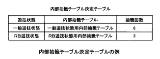
次に、図7を参照して、内部抽籤テーブル及び抽籤回数を決定するための内部抽籤テーブル決定テーブルについて説明する。図7から分かるように、この内部抽籤テーブル決定テーブルは、遊技状態に対応する内部抽籤テーブル及び抽籤回数の情報を有している。一般遊技状態の場合は、一般遊技状態用の内部抽籤テーブル(図8(a)参照)が選択され、抽籤回数として「6」が決定される。また、内部抽籤テーブルRB遊技状態の場合は、RB遊技状態用の内部抽籤テーブル(図8(b)参照)が選択され、抽籤回数として「3」が決定される。 Next, an internal lottery table and an internal lottery table determination table for determining the number of lotteries will be described with reference to FIG. As can be seen from FIG. 7, the internal lottery table determination table includes an internal lottery table corresponding to the gaming state and information on the number of lotteries. In the case of the general gaming state, the internal lottery table for the general gaming state (see FIG. 8A) is selected, and “6” is determined as the number of lotteries. In the case of the internal lottery table RB gaming state, the internal lottery table for the RB gaming state (see FIG. 8B) is selected, and “3” is determined as the number of lotteries.
抽籤回数は、内部当籤役を決定するために必要な処理をする(抽籤する)回数である。つまり、抽籤回数は、具体的には、乱数値が所定の範囲(後述の図8で説明する当籤番号に対応する下限値及び上限値により示される数値範囲)内か否かを判別する回数である。一般遊技状態の場合は、当籤番号1〜6に相当し、RB遊技状態の場合は、当籤番号1〜3に相当する。
The number of lotteries is the number of times a process necessary for determining an internal winning combination (lottery) is performed. That is, the number of lotteries is specifically the number of times that it is determined whether or not the random number value is within a predetermined range (a numerical range indicated by a lower limit value and an upper limit value corresponding to a winning number described later with reference to FIG. 8). is there. In the case of the general gaming state, it corresponds to the winning
次に、図8を参照して、内部当籤役(当籤番号と対応している)を決定するための内部抽籤処理において用いられる内部抽籤テーブルの例について説明する。 Next, an example of an internal lottery table used in an internal lottery process for determining an internal winning combination (corresponding to a winning number) will be described with reference to FIG.
この内部抽籤テーブルは、遊技状態毎に設けられ、投入枚数毎に当籤番号に対応する下限値及び上限値により示される数値範囲の情報を持っている。図8(a)は、一般遊技状態において用いられる一般遊技状態用内部抽籤テーブルを示し、図8(b)は、RB遊技状態において用いられるRB遊技状態用内部抽籤テーブルを示す。 This internal lottery table is provided for each gaming state, and has information on a numerical range indicated by a lower limit value and an upper limit value corresponding to the winning number for each inserted number. FIG. 8A shows an internal lottery table for general gaming state used in the general gaming state, and FIG. 8B shows an internal lottery table for RB gaming state used in the RB gaming state.
内部抽籤テーブルに基づく当籤番号の決定では、スタートレバー14の操作開始とともに、「0」〜「65535」の範囲内で抽出される乱数値が、図8(a)に示される当籤番号に対応する数値範囲内にあるか否かが判断される。そして、内部抽籤テーブル決定テーブル(図7)により決定された抽籤回数(一般遊技状態の場合は「6」)と同じ当籤番号から降順に、当籤番号が「1」になるまで抽出された乱数値と、当籤番号に対応する下限値及び上限値の数値範囲の比較が行われる。この抽籤の結果、乱数値が下限値及び上限値により示される数値範囲内にある場合に、対応する当籤番号に当籤している状態となる。そして、当籤した当籤番号、及び内部当籤役決定テーブル(図9参照)に基づいて内部当籤役が決定される。 In the determination of the winning number based on the internal lottery table, the random number value extracted within the range of “0” to “65535” corresponds to the winning number shown in FIG. It is determined whether it is within the numerical range. Then, random numbers extracted in descending order from the same winning number as the number of times of lottery determined by the internal lottery table determination table (FIG. 7) (“6” in the general gaming state) until the winning number becomes “1”. Then, the numerical range of the lower limit value and the upper limit value corresponding to the winning number is compared. As a result of the lottery, when the random number value is within the numerical range indicated by the lower limit value and the upper limit value, the corresponding winning number is won. Then, an internal winning combination is determined based on the winning number won and the internal winning combination determination table (see FIG. 9).
なお、当籤番号が「6」から「1」になるまで、乱数値が一度も下限値及び上限値により示される数値範囲内になかった場合、当籤番号は「0」となり、内部当籤役としてハズレが決定される。本例では、ハズレは、遊技者に付与される利益(例えば、メダルの払出し)と対応付けられた内部当籤役ではない。また、ハズレに対応する図柄の組合せは、予め設けられた内部当籤役に対応する図柄の組合せとは別の、任意の図柄の組合せであるとも考えることができるが、通常はハズレに対応する図柄の組合せは設けられていない。 If the random number is never within the numerical range indicated by the lower limit and the upper limit until the winning number is changed from “6” to “1”, the winning number is “0”, and an internal winning combination is lost. Is determined. In this example, the loser is not an internal winning combination associated with a profit (for example, a medal payout) given to the player. In addition, the symbol combination corresponding to the loss can be considered to be an arbitrary symbol combination different from the symbol combination corresponding to the internal winning combination provided in advance, but usually the symbol corresponding to the loss. No combination is provided.
また、図8(a)に示す一般遊技状態(ただし、持越区間を除く)において、投入枚数「3」の場合には、当籤番号「3」に対応する下限値及び上限値により示される数値範囲は「1785」〜「2184」であり、当籤番号「5」又は「6」に対応する下限値及び上限値により示される数値範囲は「1750」〜「1951」である。この上限値と下限値の間に入っていることが内部当籤の条件であるから、上記数値範囲を見ると、RBの当たる確率(上限値と下限値の差は“201”)は低く、ベルの当たる確率(上限値と下限値の差は“399”)は高いことが分かる。つまり、ベルはRBに比べて2倍程度の確率で当籤する可能性があるといえる。 Also, in the general gaming state shown in FIG. 8A (excluding the carryover section), in the case of the inserted number “3”, the numerical range indicated by the lower limit value and the upper limit value corresponding to the winning number “3” Is “1785” to “2184”, and the numerical value range indicated by the lower limit and the upper limit corresponding to the winning number “5” or “6” is “1750” to “1951”. Since the internal winning condition is between the upper limit value and the lower limit value, the RB hit probability (the difference between the upper limit value and the lower limit value is “201”) is low when looking at the above numerical range. It is understood that the probability of hitting (the difference between the upper limit value and the lower limit value is “399”) is high. In other words, it can be said that Bell has a chance of winning with twice the probability of RB.
本例では、RB1(当籤番号5)とRB2(当籤番号6)の数値範囲を同一としている。このため、RB1、RB2の当籤確率は同じとなる。ただし、RB1、RB2の数値範囲を異ならせることによってRB1、RB2の当籤確率を異なるようにしてもよい。 In this example, the numerical ranges of RB1 (winning number 5) and RB2 (winning number 6) are the same. For this reason, the winning probabilities of RB1 and RB2 are the same. However, the winning probability of RB1 and RB2 may be made different by making the numerical ranges of RB1 and RB2 different.
次に、図9を参照して、当籤番号に基づいて内部当籤役を決定するための内部当籤役決定テーブルの例について説明する。内部当籤役決定テーブルは、当籤番号とそれに対応する内部当籤役の情報を有している。内部当籤役の情報(即ち、フラグ)は、内部当籤役を識別するために内部当籤役のそれぞれに対応して設けられている。また、内部当籤役の情報は、8ビットの2進数のデータにより構成されている。 Next, an example of an internal winning combination determination table for determining an internal winning combination based on the winning number will be described with reference to FIG. The internal winning combination determination table includes a winning number and internal winning combination information corresponding to the winning number. The internal winning combination information (ie, flag) is provided corresponding to each internal winning combination in order to identify the internal winning combination. The internal winning combination information is composed of 8-bit binary data.
図9から分かるように、内部当籤役としては、当籤番号「6」、「5」、「4」、「3」、「2」、「1」に対応して、RB2、RB1、リプレイ、スイカ、ベル、チェリーの6つの役が内部当籤役として設定されている。当籤番号「0」の場合は、内部当籤役は「ハズレ」となる。 As can be seen from FIG. 9, the internal winning combination includes RB2, RB1, Replay, Watermelon corresponding to the winning numbers “6”, “5”, “4”, “3”, “2”, “1”. , Bell and Cherry are set as internal winning combinations. When the winning number is “0”, the internal winning combination is “losing”.
そして、当籤番号が「0」(ハズレ)の場合には、内部当籤役として「00000000」が決定される。つまり8ビット全てが「0」にセットされる。当籤番号が「1」(チェリー)では、内部当籤役として「00000001」が決定され、当籤番号が「2」(ベル)の場合には、内部当籤役として「00000010」が決定される。 When the winning number is “0” (losing), “00000000” is determined as the internal winning combination. That is, all 8 bits are set to “0”. When the winning number is “1” (cherry), “00000001” is determined as the internal winning combination, and when the winning number is “2” (bell), “00000010” is determined as the internal winning combination.
また、当籤番号が「3」(スイカ)の場合には、内部当籤役として「00000100」が決定される。同様に、当籤番号が「4」(リプレイ)の場合には、内部当籤役「00001000」が決定され、当籤番号が「5」(RB1)の場合には、内部当籤役「00010000」が決定される。当籤番号が「6」(RB2)の場合には、内部当籤役「00100000」が決定される。このように、8ビットのデータのいずれか一つのビットを「1」にすることによって、異なる内部当籤役が決定されるように構成されている。 When the winning number is “3” (watermelon), “00000100” is determined as the internal winning combination. Similarly, when the winning number is “4” (replay), the internal winning combination “00001000” is determined, and when the winning number is “5” (RB1), the internal winning combination “00010000” is determined. The When the winning number is “6” (RB2), the internal winning combination “00100000” is determined. In this way, a different internal winning combination is determined by setting any one bit of 8-bit data to “1”.
次に、図10を参照して、どのような図柄が組み合せられた時に上記図9に示した6つの内部当選役(表示役)が決定されるかについて説明する。また、決定された表示役に対応する払出枚数を決定する例についても説明する。 Next, with reference to FIG. 10, it will be described what symbols are combined to determine the six internal winning combinations (display combinations) shown in FIG. An example of determining the payout number corresponding to the determined display combination will also be described.
図10は、図柄の組合せと、表示役、払出枚数の関係を示した図柄組合せテーブルである。この図柄組合せテーブルは、投入枚数毎に、一の有効ラインにより結ばれる3つの図柄表示領域の各々に停止して表示された図柄の組合せに対応する表示役の情報と、その表示役に対応する払出枚数の情報を持っている。表示役は、基本的に、有効ラインに沿って表示される図柄の組合せを識別するための情報(即ち、データ)であり、所定の図柄の組合せ及び遊技者に付与される利益(例えば、メダルの払出し、遊技状態の作動)に対応して設けられる。ここで、表示役は、図9の内部当籤役に相当するもので、8ビットの2進数のデータにより構成される。 FIG. 10 is a symbol combination table showing the relationship among symbol combinations, display combinations, and payout numbers. This symbol combination table corresponds to the display combination corresponding to the combination of symbols stopped and displayed in each of the three symbol display areas connected by one effective line for each number of inserted symbols. Has information on the number of payouts. The display combination is basically information (that is, data) for identifying a combination of symbols displayed along the active line, and a predetermined symbol combination and a profit (for example, medal) given to the player. Payout, gaming state operation). Here, the display combination corresponds to the internal winning combination of FIG. 9, and is constituted by 8-bit binary data.
有効ラインに沿って「チェリー−ANY−ANY」の図柄の組合せが表示されると、チェリー(即ち、データ「00000001」)が表示役になり、4枚のメダルが払出される。ここで、「ANY」は、任意の図柄を示す。有効ラインに沿って「ベル−ベル−ベル」の図柄の組合せが表示されると、ベル(即ち、データ「00000010」)が表示役になり、15枚のメダルが払出される。 When the symbol combination “cherry-ANY-ANY” is displayed along the active line, cherry (that is, data “00000001”) is displayed and four medals are paid out. Here, “ANY” indicates an arbitrary symbol. When the symbol combination “bell-bell-bell” is displayed along the active line, the bell (that is, data “00000010”) is displayed and 15 medals are paid out.
有効ラインに沿って「スイカ−スイカ−スイカ」の図柄の組合せが表示されるとスイカ(即ち、データ「00000100」)が表示役になり、6枚のメダルが払出される。有効ラインに沿って「リプレイ−リプレイ−リプレイ」の図柄の組合せが表示されるとリプレイ(即ち、データ「00001000」)が表示役になり、メダルが自動投入される。有効ラインに沿って「赤7−赤7−赤7」の図柄の組合せが表示されると、RB1(即ち、データ「00010000」)が表示役になり、メダルが払出されないが、この場合、次のゲームからレギュラーボーナスゲーム(RB)が作動する。同様に、有効ラインに沿って「赤7−赤7−青7」の図柄の組合せが表示されると、RB2(即ち、データ「00100000」)が表示役になり、メダルが払出されないが、この場合、次のゲームからレギュラーボーナスゲーム(RB)が作動する。つまり、一般遊技状態からRB遊技状態に環境が変化することになる。この結果、内部当籤する確率が増大する。
When a combination of symbols “watermelon-watermelon-watermelon” is displayed along the active line, watermelon (that is, data “00000100”) is displayed and 6 medals are paid out. When the symbol combination “Replay-Replay-Replay” is displayed along the active line, the replay (that is, data “00001000”) is displayed and a medal is automatically inserted. When a combination of symbols “red 7-red 7-
なお、RB1、RB2は、異なる演出ステージを選択するために用いられる指標であり、2種類のレギュラーボーナスゲームがあることを意味するわけではない。なお、本例の図柄組合せテーブルで決定される払出枚数は、図柄の組合せに応じて決定されるが、投入したメダル枚数も考慮して払出枚数を変更することも可能である。 RB1 and RB2 are indices used to select different performance stages, and do not mean that there are two types of regular bonus games. The number of payouts determined in the symbol combination table of this example is determined according to the combination of symbols, but the number of payouts can be changed in consideration of the number of inserted medals.
次に、図11を参照して、後述するボーナス作動チェック処理(後述する図19)において参照されるボーナス作動時テーブルの例について説明する。 Next, an example of a bonus operation time table referred to in a bonus operation check process described later (FIG. 19 described later) will be described with reference to FIG.
図11に示すボーナス作動時テーブルは、RB作動中フラグをオンまたはオフに切り替えて更新するためのフラグの格納領域(作動中フラグ格納領域)、遊技可能回数カウンタ値の格納領域、及び入賞可能回数カウンタ値の格納領域を備えている。RB作動中フラグは、作動している遊技状態(即ち、現在の遊技状態)を識別するために参照されるフラグである。つまり、RB遊技状態が作動している場合には、RB作動中フラグはオンとなり、RB遊技状態が作動していない場合には、RB作動中フラグがオフとなる。 The bonus operating time table shown in FIG. 11 includes a flag storage area (operating flag storage area) for switching the RB operating flag to ON or OFF and updating it, a storage area for a possible game count counter value, and a winning possible count A counter value storage area is provided. The RB operating flag is a flag referred to for identifying an operating gaming state (that is, a current gaming state). That is, when the RB gaming state is operating, the RB operating flag is turned on, and when the RB gaming state is not operating, the RB operating flag is turned off.
遊技可能回数カウンタは、RB遊技状態において遊技可能な残りの単位遊技の回数(即ち、遊技可能回数)を識別するためのカウンタである。入賞可能回数カウンタは、RB遊技状態において小役に対応する図柄の組み合わせが表示されることが可能な残りの単位遊技の回数(即ち、入賞可能回数)を識別するためのカウンタである。RB遊技状態になると、ボーナス作動時テーブルに基づいて、遊技可能回数カウンタ及び入賞可能回数カウンタに初期値としてそれぞれ「12」及び「8」が格納される。 The game possible number counter is a counter for identifying the number of remaining unit games that can be played in the RB gaming state (that is, the number of possible games). The winning possible number counter is a counter for identifying the number of remaining unit games (that is, the number of possible winnings) in which a combination of symbols corresponding to the small combination can be displayed in the RB gaming state. In the RB gaming state, “12” and “8” are stored as initial values in the possible game number counter and the possible winning number counter, respectively, based on the bonus operation time table.
次に、図12を参照して、内部当籤役格納領域(表示役格納領域)、持越役格納領域、作動中フラグ格納領域の例について説明する。 Next, an example of an internal winning combination storing area (display combination storing area), a carryover combination storing area, and an operating flag storing area will be described with reference to FIG.
図12(a)は、内部当籤役(表示役)の情報を格納するための内部当籤役格納領域の例を示す。8ビットからなる内部当籤役格納領域において、ビット0は、チェリーに対応する格納領域である。ビット1は、ベルに対応する格納領域である。ビット2はスイカに対応する格納領域である。ビット3はリプレイに対応する格納領域である。ビット4は、RB1に対応する格納領域である。ビット5はRB2に対応する格納領域である。なお、ビット0〜5は、表示役に応じて「0」又は「1」の値をとる。ビット6、7は、未使用の格納領域であり、全て「0」の値になる。
FIG. 12A shows an example of an internal winning combination storing area for storing information of an internal winning combination (display combination). In the internal winning combination storage area consisting of 8 bits,
図12(b)は、持越役の情報を格納するための持越役格納領域の例を示す。8ビットからなる持越役格納領域において、ビット4は、RB1に対応する格納領域である。ビット5は、RB2に対応する格納領域である。ビット0〜3とビット6、7は、未使用の格納領域である。ビット4及びビット5は、「0」又は「1」の値をとる。例えば、持越役がある場合(即ち、持越区間である場合)には、持越役格納領域のRB1又はRB2に対応するビット4又はビット5に「1」が格納される(即ち、持越役格納領域に「00010000」又は「00100000」が格納される)。また、持越役がない場合(即ち、持越区間でない場合)には、持越役格納領域のRB1又はRB2に対応するビット4又はビット5に「0」が格納される(即ち、持越役格納領域に「00000000」が格納される)。遊技がRB遊技状態に変わると、この状態が複数のゲームに渡って継続するが、この継続期間中ビット4又はビット5に「1」のフラグが立つことになる。
FIG. 12B shows an example of the carryover combination storage area for storing information on the carryover combination. In the carryover combination storage area consisting of 8 bits,
図12(c)は、RB作動中フラグ格納領域の例を示す。8ビットからなる作動中フラグ格納領域において、ビット0は、RB作動中フラグに対応する格納領域である(図11のボーナス作動時テーブル参照)。ビット1〜7は、未使用の格納領域である。ビット0だけが「0」又は「1」の値をとり、ビット1〜7は全て「0」の値をとる。
FIG. 12C shows an example of the RB operating flag storage area. In the operating flag storage area consisting of 8 bits,
ここで、作動中フラグ格納領域のRB作動中フラグに対応するビット0に「1」が格納されている場合(即ち、作動中フラグ格納領域が「00000001」となっている場合)には、RB作動中フラグがオンとなり、RB遊技状態であることを意味する。一方、作動中フラグ格納領域のRB作動中フラグに対応するビット0に「0」が格納されている場合(即ち、作動中フラグ格納領域が「00000000」である場合)は、一般遊技状態であることを示している。
Here, when “1” is stored in
次に、図13を参照して、表示役によって異なる演出ステージを決定するために参照する第1の演出ステージ変更テーブルの例について説明する。 Next, an example of a first effect stage change table that is referred to in order to determine an effect stage that varies depending on the display combination will be described with reference to FIG.
本例では、「RB1」、「RB2」を特別な表示役とする。この特別な表示役が、有効ラインに沿って複数回表示されることを条件として、演出ステージが変わり、液晶表示部4bに表示される画像が変化するようになっている。第1の演出ステージ変更テーブルは、図5に示したワークRAM89に保存されているテーブルであり、表示された特別な表示役(RB1とRB2)を3個まで格納する表示役情報格納部とこれに対応する演出ステージから構成されている。
In this example, “RB1” and “RB2” are special display combinations. On the condition that this special display combination is displayed a plurality of times along the effective line, the stage is changed, and the image displayed on the liquid
遊技者の停止操作により表示窓に表示された特別な表示役は、表示役情報格納部に格納される。そして、この特別な表示役が計3回表示されると演出ステージが切り換わる。ここで、図柄が「赤7−赤7−赤7」と揃った場合、特別な表示役としてRB1が格納される。また、図柄が「赤7−赤7−青7」と揃った場合、特別な表示役としてRB2が格納される。例えば、表示役情報格納部に、「赤7−赤7−赤7(RB1)」−「赤7−赤7−赤7(RB1)」−「赤7−赤7−赤7(RB1)」が格納されると、演出ステージとして「夕方ステージ(プレミア)」に変化する。また、表示役情報格納部に、「赤7−赤7−赤7(RB1)」−「赤7−赤7−赤7(RB1)」−「赤7−赤7−青7(RB2)」が格納されると、「夕方ステージ」に変化する。表示役情報格納部に、「赤7−赤7−赤7(RB1)」−「赤7−赤7−青7(RB2)」−「赤7−赤7−青7(RB2)」が格納されると、「夜ステージ」に変化する。
The special display combination displayed on the display window by the player's stop operation is stored in the display combination information storage unit. When this special display combination is displayed a total of three times, the effect stage is switched. Here, when the symbols are aligned with “red 7-red 7-
また、表示役情報格納部に「赤7−赤7−赤7(RB1)」−「赤7−赤7−青7(RB2)」−「赤7−赤7−赤7(RB1)」が格納されると「夕方ステージ」に変化する。表示役情報格納部に「赤7−赤7−青7(RB2)」−「赤7−赤7−青7(RB2)」−「赤7−赤7−青7(RB2)」が格納されると「夜ステージ(プレミア)」に変化する。表示役情報格納部に、「赤7−赤7−青7(RB2)」−「赤7−赤7−青7(RB2)」−「赤7−赤7−赤7(RB1)」が格納されると「夜ステージ」に変化し、表示役情報格納部に「赤7−赤7−青7(RB2)」−「赤7−赤7−赤7(RB1)」−「赤7−赤7−赤7(RB1)」が格納されると「夕方ステージ」に変化する。 In addition, “Red 7-Red 7-Red 7 (RB1)”-“Red 7-Red 7-Blue 7 (RB2)”-“Red 7-Red 7-Red 7 (RB1)” are displayed in the display combination information storage unit. When stored, it changes to “Evening Stage”. "Red 7-Red 7-Blue 7 (RB2)"-"Red 7-Red 7-Blue 7 (RB2)"-"Red 7-Red 7-Blue 7 (RB2)" are stored in the display combination information storage unit. Then it changes to “Night Stage (Premier)”. "Red 7-Red 7-Blue 7 (RB2)"-"Red 7-Red 7-Blue 7 (RB2)"-"Red 7-Red 7-Red 7 (RB1)" are stored in the display combination information storage unit. Then, it changes to “Night Stage”, and “Red 7-Red 7-Blue 7 (RB2)”-“Red 7-Red 7-Red 7 (RB1)”-“Red 7-Red” is displayed in the display combination information storage section. When “7-Red 7 (RB1)” is stored, it changes to “Evening stage”.
また、表示役情報格納部に「赤7−赤7−青7(RB2)」−「赤7−赤7−赤7(RB1)」−「赤7−赤7−青7(RB2)」が格納されると「夜ステージ」に変化する。表示役情報格納部に、RB1とRB2の特別な表示役が3個格納されない場合は、演出ステージは「昼ステージ」のままで切り換わらない。 Also, “Red 7-Red 7-Blue 7 (RB2)”-“Red 7-Red 7-Red 7 (RB1)”-“Red 7-Red 7-Blue 7 (RB2)” are displayed in the display combination information storage unit. When stored, it changes to "Night Stage". When three special display combinations of RB1 and RB2 are not stored in the display combination information storage unit, the effect stage remains “daytime stage” and does not switch.
このように、本例の遊技機1では、一般遊技状態において、特別な表示役が3回有効ラインに沿って表示されることを条件として、液晶表示部4bに表示される演出ステージを切り換えるようにしている。
Thus, in the
<主制御回路の動作説明>
次に、図14のフローチャートを参照して、メインCPU(即ち、CPU45)の制御動作、すなわち主制御回路41の処理について説明する。
<Description of main control circuit operation>
Next, the control operation of the main CPU (that is, the CPU 45), that is, the processing of the
最初に、遊技場の従業員等が遊技機1の図示しない電源スイッチをオンすることで、CPU45は、初期化処理を開始する(ステップS1)。初期化処理として、CPU45は、RAM44が正常か否かのチェックや入出力ポートの初期化等を行う。また、CPU45は、リセットスイッチ60と設定用鍵型スイッチ61から供給される信号に基づいて、決定された設定値をRAM44の所定の領域に格納する処理を行う。初期化処理が終了すると、CPU45は、ゲーム終了時のRAM44の指定格納領域(例えば、内部当籤役格納領域の情報)を消去する(ステップS2)。
First, when an employee of the game hall turns on a power switch (not shown) of the
ステップS2でRAM44の指定格納領域が消去されると、CPU45は、後述するメダル受付・スタートチェック処理(図15参照)を行う(ステップS3)。そして、メダル受付・スタートチェック処理後に、CPU45は、乱数値を抽出し、RAM44の乱数値格納領域に抽出した乱数値を格納する(ステップS4)。CPU45が抽出した乱数値は、内部抽籤処理において使用される。
When the designated storage area of the
次に、CPU45は、遊技状態監視処理を行う(ステップS5)。遊技状態監視処理において、RB作動中フラグがオンであれば、CPU45は、RB遊技状態を示す識別子(いわゆるフラグ)をRAM44に格納する。RB作動中フラグがオフであれば、一般遊技状態であるとみなされる。RB遊技状態であれば、RB遊技状態を示す識別子(RB作動中フラグ)がボーナス作動時テーブル(図11参照)に格納される。
Next, the
ステップS5の遊技状態監視処理が終了すると、CPU45は、後述する内部抽籤処理(図16参照)を行う(ステップS6)。この内部抽籤処理で内部当籤役が抽籤されると、CPU45は、スタートコマンドを副制御回路71に送信する(ステップS7)。このスタートコマンドは、一般又はRB遊技状態の識別情報及び内部当籤役等の情報を含むコマンドである。
When the gaming state monitoring process in step S5 ends, the
次に、CPU45は、全リールの回転開始を要求する(ステップS8)。具体的には、CPU45は、停止ボタン15L,15C,15Rのそれぞれに対応する、後述する3つの有効停止ボタンフラグを全てオンに更新する。全ての有効停止ボタンフラグがオンに更新されることで、3個の停止ボタン15L,15C,15Rの押圧操作が有効になる。
Next, the
続いて、CPU45は、後述するリール停止制御処理(図17参照)を行う(ステップS9)。リール停止制御処理が終了すると、CPU45は、表示窓21L,21C,21Rに表示された図柄の組合せと、図柄組合せテーブル(図10参照)とに基づいて表示役とメダルの払出枚数を決定する(ステップS10)。この際に、有効ラインカウンタについても考慮される。
Subsequently, the
具体的には、CPU45は、決定された内部当籤役に対応する図柄の組合せが有効ラインカウンタに対応する有効ラインに沿って表示されるか否かを判断する。その後、有効ラインカウンタを「1」減算する処理を行い、これを有効ラインカウンタが「0」になるまで繰り返す。有効ラインカウンタには、後述するメダル受付・スタートチェック処理(図15参照)により「5」が格納されるので、CPU45は、5本の有効ラインのそれぞれについて表示役とメダルの払出枚数を決定する。
Specifically, the
また、表示役にリプレイが決定された場合には、CPU45は、自動投入カウンタに「3」を格納する。リプレイが表示役である場合に、自動投入カウンタは、次回のゲームで自動的に投入するメダルの枚数を計数する。
If replay is determined for the display combination, the
表示役と払出枚数が決定されると、CPU45は、表示役コマンドを副制御回路71に送信する処理を行う(ステップS11)。表示役コマンドは、ステップS10で決定された表示役とメダルの払出枚数の情報を含んでいる。続いて、CPU45は、決定されたメダルの払出枚数に基づいてメダルを払出す(ステップS12)とともに、RB作動中フラグがオンであるか否かを判断する(ステップS13)。
When the display combination and the number of payouts are determined, the
判断ステップS13で、RB作動中フラグがオンであると判断された場合には、CPU45は、ボーナス終了チェック処理(図18参照)を行う(ステップS14)。また、判断ステップS13において、RB作動中フラグがオフであると判断された場合、又はステップS14のボーナス終了チェック処理が終了した場合は、CPU45は、ボーナス作動チェック処理(図19参照)を行い(ステップS15)、処理を再びステップS2に戻す。
If it is determined in the determination step S13 that the RB operating flag is on, the
次に、図15を参照して、遊技者が行うメダルの投入操作と、遊技の開始操作を検出するメダル受付・スタートチェック処理の例について説明する。 Next, an example of a medal insertion operation and a medal acceptance / start check process for detecting a game start operation performed by the player will be described with reference to FIG.
始めに、CPU45は、メダルの投入処理があったか否かを判別する(ステップS21)。具体的には、CPU45は、メダルセンサ16S又はBETスイッチ11,12,13からの入力のチェックを行い、メダルセンサ16S又はBETスイッチ11,12,13からの入力があるか否かを判別する。メダルセンサ16S又はBETスイッチ11,12,13のいずれからも投入処理を検出しない場合には、CPU45は、処理をステップS28に移す。他方、メダルセンサ16Sがオンされた場合、あるいは、BETスイッチ11〜13のいずれかが押圧操作された場合は、その種別、投入枚数カウンタ及びクレジットに基づいて、投入枚数カウンタに加算する値を算出した上で、投入処理がされたと判定する。その後は、投入枚数カウンタが「0」になるまでスタートレバーの監視を行うことなく、ステップS21からステップS28までの処理を繰り返して行う。
First, the
判断ステップS21で投入処理がなされたと判定されると、CPU45は、投入枚数カウンタ又はクレジットカウンタを更新する(ステップS22)。具体的には、ステップS21の処理でメダルセンサ16Sからの入力があった場合に、CPU45は、投入枚数カウンタの値に「1」を加算する。ここで、投入枚数カウンタは、投入されたメダルの枚数を計数するカウンタであり、クレジットカウンタは、クレジットされたメダルの枚数を計数するためのカウンタである。
If it is determined in the determination step S21 that the insertion process has been performed, the
また、BETスイッチ11,12,13からの入力があった場合には、CPU45は、投入された値を投入枚数カウンタに加算する。また、前回のゲームでリプレイに対応する図柄の組合せが表示された場合には、自動投入カウンタの値に基づいて投入枚数カウンタの値を更新する。投入枚数カウンタの加算が禁止された場合には、投入枚数カウンタの代わりにクレジットカウンタの値を加算する。投入枚数カウンタ又はクレジットカウンタを更新すると、CPU45は、有効ラインカウンタに「5」を格納し(ステップS23)、ベットコマンド送信を行う(ステップS24)。
When there is an input from the BET switches 11, 12, and 13, the
次に、CPU45は、作動中フラグ格納領域(図11参照)のRB作動中フラグがオンか否かを判別する(ステップS25)。この判断ステップS25において、RB作動中フラグがオンであると判断された場合には、CPU45は、処理をステップS27に移す。他方、RB作動中フラグがオフであると判断された場合には、続いて、CPU45は、投入枚数カウンタの値が「3」であるか否かを判別する(ステップS26)。投入枚数カウンタの値が「3」ではない場合には、CPU45は、処理をステップS28に移す。
Next, the
判断ステップS25においてRB作動中フラグがオンである場合、又はRB作動中フラグはオフであるが判断ステップS26において投入枚数カウンタが「3」であると判定された場合には、CPU45は、投入枚数カウンタへの加算を禁止する(ステップS27)。これは、一般遊技状態においては開始操作が有効となる最大の投入枚数「3」であり、RB遊技状態においては開始操作が有効となる最大の投入枚数が「1」であるからである。
If the RB operating flag is ON in determination step S25, or if the RB operating flag is OFF but it is determined in determination step S26 that the input number counter is “3”, the
ステップS27で投入枚数カウンタへの加算が禁止された場合、又は判断ステップS26において投入枚数カウンタが「3」ではないと判断された場合、又は判断ステップS21で投入処理がないと判断された場合には、次に、CPU45は、投入枚数カウンタの値が「1」以上であるか否かを判別する(ステップS28)。投入枚数カウンタの値が「1」未満の場合、つまり「0」のときには、CPU45は、処理をステップS21に移す。
When addition to the insertion number counter is prohibited in step S27, or when it is determined in determination step S26 that the insertion number counter is not "3", or when it is determined that there is no insertion processing in determination step S21 Next, the
他方、投入枚数カウンタの値が「1」以上である場合には、CPU45は、スタートスイッチ14Sがオンであるか否かを判別する(ステップS29)。具体的には、CPU45は、スタートレバー14の操作に基づくスタートスイッチ14Sからの入力があるか否かを判別する。スタートスイッチ14Sからの入力がある場合には、CPU45は、処理をメインフロー(図14参照)に移す。他方、スタートスイッチ14Sからの入力がない場合には、CPU45は、処理を再びステップS21に移す。
On the other hand, when the value of the insertion number counter is “1” or more, the
次に、図16のフローチャートを参照して、遊技状態等に依存した内部当籤役を決定する内部抽籤処理の例について説明する。 Next, an example of an internal lottery process for determining an internal winning combination depending on the gaming state or the like will be described with reference to the flowchart of FIG.
最初に、CPU45は、内部抽籤テーブル決定テーブル(図7)に基づいて、遊技状態に応じた内部抽籤テーブルの種別と抽籤回数を決定する(ステップS41)。即ち、一般遊技状態であれば抽籤回数を「6」に設定し、RB遊技状態であれば抽籤回数を「3」に設定する。次に、CPU45は、図12(b)の持越役格納領域にRB1又はRB2の識別子が格納されているか否か、すなわち、持越役格納領域のRB1に対応するビット4又はRB2に対応するビット5に「1」が格納されているか(即ち、持越役の有無)を判別する(ステップS42)。
First, based on the internal lottery table determination table (FIG. 7), the
判断ステップS42において、持越役格納領域のビット4又はビット5に「1」が格納されていると判断された場合、CPU45は、抽籤回数を「4」に変更する(ステップS43)。ここで抽籤回数を「4」に変更するのは、持越役格納領域にRBの識別子(本例では、RB1又はRB2)が格納されている場合は、再度RBの抽籤をすることがないからである。つまり、抽籤回数は内部当籤役決定テーブル(図9参照)の当籤番号1〜4までの4回だけになる。
In the determination step S42, when it is determined that “1” is stored in
また、判断ステップS42において、持越役格納領域のビット4又はビット5に「1」が格納されていない場合には、CPU45は、抽籤回数を変更することなく、処理をステップS44に進める。続いて、CPU45は、ステップS41で決定された抽籤回数又はステップS43で変更された抽籤回数と同じ値を当籤番号としてセットする(ステップS44)。言い換えると、上記の6つの当籤番号1〜6について抽籤を行うことになる。
Further, in the determination step S42, when “1” is not stored in the
続いて、CPU45は、図示しない乱数値格納領域に格納されている乱数値と、投入枚数に応じた内部抽籤テーブル(図8参照)の下限値及び上限値とを比較する(ステップS45)。具体的には、CPU45は、ステップS41で決定された内部抽籤テーブルを参照し、当籤番号に基づいて、下限値(L)を取得し、RAM44における乱数値格納領域に格納されている乱数値(R)から下限値(L)を減算する(R−L)。また、CPU45は、ステップS41で決定された内部抽籤テーブルを参照し、当籤番号に基づいて、上限値(U)を取得し、RAM44における乱数値格納領域に格納されている乱数値(R)から上限値(U)を減算する(R−U)。
Subsequently, the
そして、このようにして算出された(R−L)と(R−U)に基づいて、CPU45は、乱数値が下限値以上かつ上限値以下であるか否かを判別する(ステップS46)。具体的には、求められた(R−L)が正の値であり、かつ(R−U)が負の値であるか否かによって判別する。この判断ステップS46において、乱数値が下限値以上かつ上限値以下でない場合には、つまり上限値と下限値の間にない場合は、CPU45は、処理をステップS51に移す。判断ステップS46において、乱数値が下限値以上かつ上限値以下であると判断された場合には、CPU45は、内部当籤役決定テーブル(図9)を参照し、当籤番号に基づいて内部当籤役決定テーブルより内部当籤役を決定する(ステップS47)。
Then, based on (R−L) and (R−U) calculated in this way, the
このようにして内部当籤役が決定されると、次に、CPU45は、決定された内部当籤役がRB1又はRB2であるか否かを判別する(ステップS48)。そして、この判断ステップS48で内部当籤役がRB1又はRB2であると判別された場合には、CPU45は、持越役格納領域(図12(b)参照)にRB1の識別子「00010000」又はRB2の識別子「00100000」を格納する(ステップS49)。他方、判断ステップS48で内部当籤役がRBではないと判別された場合には、CPU45は、処理をステップS50に移す。
When the internal winning combination is determined in this way, the
そして、ステップS49で持越役格納領域にRB1又はRB2の識別子を格納した場合、又は判断ステップS48で内部当籤役がRB1又はRB2ではないと判別された場合は、CPU45は、内部当籤役と持越役格納領域の論理和を内部当籤役格納領域に格納する(ステップS50)。そして、CPU45は、現在格納されている抽籤回数から「1」を減算する(ステップS51)。また、判断ステップS46で乱数値が下限値と上限値の間に収まっていないと判断された場合も、ステップS51において抽籤回数が「1」減算される。
If the identifier of RB1 or RB2 is stored in the carryover combination storage area in step S49, or if it is determined in step S48 that the internal winning combination is not RB1 or RB2, the
次に、CPU45は、ステップS51で「1」減算した抽籤回数が「0」になったか否かを判別する(ステップS52)。抽籤回数が「0」である場合には、CPU45は、内部当籤役格納領域と持越役格納領域の論理和を内部当籤役格納領域に格納する(ステップS53)。当初、内部当籤役格納領域は「0」であり、このまま「0」であれば、いわゆるハズレとなる。他方、判断ステップS52で抽籤回数が「0」ではないと判断された場合には、CPU45は、処理を再びステップS44に移し、抽籤回数と同じ値を当籤番号としてセットする。
Next, the
次に、図17のフローチャートを参照して、内部当籤役や遊技者による停止操作のタイミング等に基づいてリール3L,3C,3Rの回転を停止させるリール停止制御処理の例について説明する。
Next, an example of a reel stop control process for stopping the rotation of the
先ず、CPU45は、有効な停止ボタンが押圧操作されたか否か、すなわち、回転しているリール3L,3C,3Rに対応する停止ボタン15L,15C,15Rの押圧操作を停止スイッチ15LS,15CS,15RSが検出したか否かを判別する(ステップS61)。有効な停止ボタンが押圧操作されたと判定された場合は、CPU45は、押圧操作が行われた停止ボタン15L,15C,15Rに対応する有効停止ボタンフラグをオフに更新する(ステップS62)。他方、有効な停止ボタンが押圧操作されていないと判定された場合は、CPU45は、再び処理をステップS61に移す。
First, the
ここで、有効停止ボタンフラグは、押圧操作された停止ボタン15L,15C,15Rに対応するリール3L,3C,3Rが回転しているか否かを識別するための情報であり、停止ボタン15L,15C,15Rの各々に対応して3つ設けられている。押圧操作された停止ボタン15L,15C,15Rに対応するリール3L,3C,3Rが回転している場合には、当該停止ボタン15L,15C,15Rに対応する有効停止ボタンフラグはオンである。押圧操作された停止ボタン15L,15C,15Rに対応するリール3L,3C,3Rが回転していない場合には、当該停止ボタン15L,15C,15Rに対応する有効停止ボタンフラグはオフである。
Here, the effective stop button flag is information for identifying whether or not the
ここで、本例の遊技機1では、図柄の組合せの引込みの相対的な優先順位の情報を持つ引込優先順位テーブル(図示せず)が設けられており、このテーブルに基づいて、リール3L,3C,3Rの停止制御が行われる。本例の引込優先順位テーブルは、リプレイに最も高い優先順位を付し、次いでボーナス、そして小役の順序となるような優先順位を規定している。
Here, in the
ここで、「引込み」とは、基本的に、有効ラインが結ぶ図柄表示領域(以下、「有効図柄表示領域」という。)に、最大の滑り駒数の範囲内で引込み対象役に対応する図柄の組合せを構成する図柄(以下、「引込み対象図柄」という。)を表示するように、停止操作が行われた停止ボタンに対応するリールを停止させることをいう。 Here, “retraction” basically refers to a symbol corresponding to a winning combination within the maximum number of sliding symbols in a symbol display area (hereinafter referred to as “effective symbol display area”) connected by an active line. This means that the reel corresponding to the stop button for which the stop operation has been performed is stopped so as to display a symbol (hereinafter referred to as a “drawing target symbol”) that constitutes the combination.
ステップS62において、停止ボタンの押圧操作が無効化されると、CPU45は、内部当籤役及び図柄カウンタに基づいて、滑り駒数を決定する(ステップS63)。続いて、停止制御位置待ち処理を行う(ステップS64)。この処理は、ステップS63で設定した滑り駒数に基づいて、回転しているリール3L,3C,3Rが順次停止位置に停止するまでの時間を待つ処理である。続いて、CPU45は、リール停止コマンドを送信する(ステップS65)。このリール停止コマンドには、ステップS63で決定された滑り駒数の情報等が含まれている。
In step S62, when the pressing operation of the stop button is invalidated, the
ステップS64でリール停止コマンドが送信されると、続いて、CPU45は、押圧操作が有効な停止ボタンがあるか否か、すなわち、3つの有効な停止ボタンフラグのうちいずれがオンであるか否かを判別する(ステップS66)。このとき、リール3L,3C,3Rの3個の回転しているリールがあるので、それに対応する3つの有効停止ボタンフラグのうち、一つでも有効な停止ボタンがあれば、CPU45は、処理を再びステップS61に移す。他方、全てのリール3L,3C,3Rの回転が停止し、3つの有効停止ボタンフラグが全てオフである場合には、CPU45は、処理をメインフロー(図14参照)に移す。
When the reel stop command is transmitted in step S64, the
次に、図18を参照して、図14のメインフローに示すステップS14のボーナス終了チェック処理について説明する。ボーナス終了チェック処理は、ボーナスゲームの終了条件を満たした場合にボーナスゲームを終了するためのチェックを行う処理である。 Next, with reference to FIG. 18, the bonus end check process in step S14 shown in the main flow of FIG. 14 will be described. The bonus end check process is a process for performing a check for ending the bonus game when a bonus game end condition is satisfied.
始めに、CPU45は、図柄組合せテーブル(図10参照)に示される表示役(内部当籤役)に該当する入賞が成立したか否かを判別する(ステップS71)。この判断ステップS71において、入賞が成立したと判定された場合には、CPU45は、入賞可能回数カウンタから「1」減算し(ステップS72)、続いて、入賞可能回数カウンタの値が「0」になったか否か(即ち、入賞可能回数は「0」であるか否か)を判別する(ステップS73)。判断ステップS71において、入賞が成立していないと判定された場合には、CPU45は、処理をステップS74に進める。
First, the
一方、判断ステップS73において、入賞可能回数カウンタの値が「0」であると判断された場合には、CPU45は、それ以降の処理をステップS76のRB終了時処理に移す。他方、判断ステップS73において、入賞可能回数カウンタの値が「0」でないと判定された場合には、CPU45は、遊技可能回数カウンタの値から「1」減算し(ステップS74)、続いて、遊技可能回数カウンタの値が「0」であるか否か(即ち、遊技可能回数が「0」であるか否か)を判別する(ステップS75)。
On the other hand, if it is determined in the determination step S73 that the value of the winning possibility counter is “0”, the
そして、判断ステップS75において、遊技可能回数が「0」であると判定された場合には、CPU45は、作動中フラグ格納領域をクリアするRB終了時処理(ステップS76)を行う。そして、さらにCPU45は、ボーナスゲームが終了したことを告げるボーナス終了コマンドを副制御回路71に送る(ステップS77)。そして、その後の処理をメインフロー(図14参照)に移す。他方、判断ステップS75において、遊技可能回数カウンタが「0」ではないと判定された場合には、CPU45は、ステップS76のRB終了時処理を行うことなく、処理をメインフローに移す。
If it is determined in the determination step S75 that the number of possible games is “0”, the
次に、図19を参照して、図14のメインフローに示すステップS15のボーナス作動チェック処理について説明する。ボーナス作動チェック処理は、決定された表示役の種別等に基づいてボーナスゲーム等を作動させるためのチェックを行う処理である。 Next, with reference to FIG. 19, the bonus operation check process in step S15 shown in the main flow of FIG. 14 will be described. The bonus operation check process is a process for performing a check for operating a bonus game or the like based on the determined display combination type or the like.
最初に、CPU45は、図10の図柄組合せテーブルにおいて表示役(内部当籤役)がRB1又はRB2であるか否かを判別する(ステップS81)。すなわち、図柄として「赤7−赤7−赤7(RB1)」又は「赤7−赤7−青7(RB2)」が有効ライン上に揃ったか否かが判別される。そして、この判断ステップS81において、表示役がRB1又はRB2であると判定された場合には、CPU45は、ボーナス作動時テーブル(図11参照)に基づいてボーナス作動時処理を行う(ステップS82)。
First, the
次に、ステップS82のボーナス作動時の処理が終了すると、CPU45は、持越役格納領域をクリアする。具体的には、CPU45は、例えば、表示役がRB1又はRB2である場合には、ボーナス作動時テーブルを参照して、表示役に対応する作動中フラグ(即ち、RB作動中フラグ)をオンに更新する。そして、CPU45は、持越役格納領域をクリアして(ステップS83)、処理をメインフロー(図14参照)に移す。判断ステップS81において、表示役がRB1及びRB2でないと判断された場合には、CPU45は、ボーナス作動チェック処理を終了し、処理をメインフローに移す。
Next, when the bonus activation process in step S82 is completed, the
<副制御回路の動作説明>
次に、図20のフローチャートを参照して、図5に示す副制御回路71の画像制御回路71aの処理について説明する。
<Description of operation of sub-control circuit>
Next, processing of the
最初に、遊技場の従業員等が遊技機1の図示しない電源スイッチをオンすることで、副制御回路71が初期化処理を開始する(ステップS91)。この初期化処理としては、画像処理回路71aの画像制御マイコン81がワークRAM89のチェックを行う。また、音・ランプ制御回路71bの音・ランプ制御マイコン91がワークRAM97のチェックを行う。これらのチェックはワークRAMが正常に動作するかどうかを確認する処理である。この副制御回路71の初期化処理は、主制御回路41の初期化処理(図14のステップS1参照)と同じタイミングで行われる。
First, the
初期化処理が終了すると、画像制御マイコン81は、主制御回路41から供給される様々なコマンドの入力監視処理を行う(ステップS92)。主制御回路41から供給されるコマンドには、例えば遊技を開始するスタートコマンドや、停止ボタン15L,15C,15Rの停止操作で発生する停止コマンド等がある。そして、画像制御マイコン81は、受け付けたコマンドに対して、後述するコマンド入力処理(図21参照)を行う(ステップS93)。
When the initialization processing is completed, the
次に、画像制御マイコン81は、演出ステージを変更する条件を満たしている場合に、演出ステージ変更処理(後述の図23参照)を行う(ステップS94)。演出ステージ変更処理が終了すると画像制御マイコン81から、音・ランプ制御マイコン91に演出制御コマンドを送信する(ステップS95)。音・ランプ制御マイコン91は受信した演出制御コマンドに基づいて、液晶表示部4bにおける演出ステージの表示、LED類101,ランプ類102の発光、スピーカ2L,2Rの効果音の放音等の制御を行う。ステップS95のコマンド出力処理を終了すると、ステップS92に戻って、引き続きコマンドの入力監視処理を行う。
Next, the
次に、図21を参照して、主制御回路41から副制御回路71の画像制御マイコン81に送信されたコマンドに対する画像制御マイコン81の処理(コマンド入力処理)の例について説明する。
Next, an example of processing (command input processing) of the
始めに、画像制御マイコン81は、主制御回路41から供給されたコマンドの中に未処理のコマンドがあるか否かを判断する(ステップS101)。未処理のコマンドがないと判断された場合、コマンド入力処理を終了し、処理を演出ステージ変更処理(図20のステップS94)に移す。未処理のコマンドがあると判断された場合、コマンドの種類に応じた実行処理を行う(ステップS102)。コマンドの種類に応じた実行処理については、後述する表示役コマンド受信時処理(図22参照)で詳細に説明する。
First, the
コマンドの種類に応じた実行処理が終了すると、未処理のコマンドを処理済みに設定する(ステップS103)。このとき、画像制御マイコン81は、未処理のコマンドを実行するために確保したワークRAM89の領域を開放し、未処理のコマンドを処理済みにして次の処理である演出ステージ変更処理(図20のステップS94)に移行する。
When the execution process corresponding to the command type is completed, the unprocessed command is set to processed (step S103). At this time, the
次に、図22を参照して、画像制御マイコン81が受け付けた表示役コマンドに対して行う表示役コマンド受信時処理の例について説明する。図22の表示役コマンド受信時処理は、コマンドの種類に応じた実行処理(図21のステップS102)の処理の中で、特に画像制御マイコン81が表示役コマンドを受信したときに呼び出される処理である。
Next, with reference to FIG. 22, an example of a display combination command reception process performed for the display combination command received by the
始めに、画像制御マイコン81は、主制御回路41から供給された表示役コマンドが、特別な表示役(本例では、RB1又はRB2)の情報を含むか否かを判断する(ステップS111)。表示役コマンドが、特別な表示役の情報を含まない場合、処理をコマンド入力処理(図21のステップS103)に移す。
First, the
表示役コマンドが、特別な表示役の情報を含む場合、受信した特別な表示役を第1の演出ステージ変更テーブル(図13参照)の表示役情報格納部に格納するとともに、表示役情報格納カウンタに「1」を加算する(ステップS112)。この表示役格納カウンタは、表示役情報格納部に格納した特別な表示役の個数をカウントするカウンタである。表示役情報格納部と表示役情報格納カウンタは、ワークRAM89にその領域が確保されている。
When the display combination command includes special display combination information, the received special display combination is stored in the display combination information storage unit of the first stage change table (see FIG. 13), and the display combination information storage counter is stored. “1” is added to (step S112). This display combination storing counter is a counter that counts the number of special display combinations stored in the display combination information storage unit. The areas of the display combination information storage unit and the display combination information storage counter are secured in the
表示役情報格納カウンタは、特別な表示役が表示された場合、その表示回数を最大「3」までカウントすることができる。特別な表示役が表示役情報格納部に格納され、表示役情報格納カウンタに「1」が加算されると、処理が図21のステップS103に移行される。 When a special display combination is displayed, the display combination information storage counter can count the number of times of display to a maximum of “3”. When the special display combination is stored in the display combination information storage unit and “1” is added to the display combination information storage counter, the process proceeds to step S103 in FIG.
本例の遊技機1では、演出ステージが移行すると、液晶表示部4bへの画像の表示や、LED類101,ランプ類102等による発光等が移行した演出ステージに基づいて行われる。ここで、演出ステージに移行する前であっても、遊技者が演出ステージを選択するための情報として、表示役情報格納部に格納した特別な表示役についての情報(種別と格納順序)を液晶表示部4bで表示するようにしてもよい。
In the
次に、図23を参照して、画像制御マイコン81が行う演出ステージ変更処理の例について説明する。
演出ステージ変更処理では、最初に、表示役情報格納カウンタが「3」であるか否かが判断される(ステップS121)。表示役情報格納カウンタが「3」ではないと判断された場合、処理をコマンド出力処理(図20のステップS95)に移す。表示役情報格納カウンタが「3」であると判断された場合、第1の演出ステージ変更テーブルの表示役情報格納部に格納されている特別な表示役の種別と格納順序に基づいて、演出ステージを変更する(ステップS122)。
Next, an example of the effect stage changing process performed by the
In the effect stage change process, it is first determined whether or not the display combination information storage counter is “3” (step S121). If it is determined that the display combination information storage counter is not “3”, the process proceeds to a command output process (step S95 in FIG. 20). When it is determined that the display combination information storage counter is “3”, the production stage is based on the type and storage order of the special display combination stored in the display combination information storage unit of the first production stage change table. Is changed (step S122).
演出ステージを変更すると、第1の演出ステージ変更テーブルの表示役情報格納部に格納された表示役情報(特別な表示役)を消去し、表示役情報格納カウンタを「0」にする(ステップS123)。その後、処理をコマンド出力処理(図20のステップS95)に移す。 When the production stage is changed, the display combination information (special display combination) stored in the display combination information storage unit of the first production stage change table is deleted, and the display combination information storage counter is set to “0” (step S123). ). Thereafter, the process proceeds to a command output process (step S95 in FIG. 20).
以上、図14から図23のフローチャートに基づいて、本発明の第1の実施の形態例における構成と動作の説明を行った。第1の実施の形態によれば、演出ステージを変更するために、参照される特別な表示役として、「RB1」と「RB2」を用意した。そして、遊技者が揃える特別な表示役を、画像制御マイコン81のワークRAM89に設けた第1の演出ステージ変更テーブル(図13参照)の表示役情報格納部に格納するようにした。そして、表示役情報格納部に特別な表示役が3個格納されることを条件として、格納された特別な表示役の種別と格納順序に応じて、通常ステージから特別な演出ステージに移行するようにした。このようにすることで、前回のリールの回転開始から今回の始動開始までの時間や、リールの回転開始から回転停止までの時間に応じて、遊技者が操作を休止しなくてもよいことになる。これにより、遊技者は、所望の演出を見るために、操作を休止する必要なくなるので、遊技機を連続して稼動させながら演出を楽しむことができるようになる。
The configuration and operation of the first embodiment of the present invention have been described above based on the flowcharts of FIGS. According to the first embodiment, “RB1” and “RB2” are prepared as special display combinations to be referred to in order to change the production stage. And the special display combination which a player arranges was stored in the display combination information storage part of the 1st production stage change table (refer FIG. 13) provided in the
また、遊技者が所望の演出ステージを見るためには、特別な表示役を意図的に表示させる必要がある。このため、熟練した遊技者にとっては、特別な表示役を意図的に表示させることで、所望の演出ステージに変化させることができる。このため、自己の遊技に関する技量を衆目に見せることもできる。他方、非熟練遊技者であれば、特別な表示役を揃えられないために、容易に演出ステージを表示させることができない。このように、熟練遊技者と非熟練遊技者との間の技量の差が反映されるため、非熟練遊技者はより一層遊技に熟練したいと思う気持ちが強くなるといえる。 Further, in order for the player to see a desired stage, it is necessary to intentionally display a special display combination. For this reason, it is possible for a skilled player to change to a desired stage by intentionally displaying a special display combination. For this reason, it is also possible to show the skill related to his game to the public. On the other hand, if it is an unskilled player, since a special display combination cannot be prepared, a production stage cannot be displayed easily. In this way, since the difference in skill between the skilled player and the unskilled player is reflected, it can be said that the unskilled player has a greater desire to become more skilled in the game.
また、本例の遊技機では、演出ステージが移行すると、液晶表示部4bへの画像の表示や、LED類101,ランプ類102等による発光等が移行した演出ステージに基づいて行われる。そして、演出ステージに移行する前であっても、表示役情報格納部に格納した特別な表示役についての情報を液晶表示部4bで表示することもできる。これによって、遊技者は表示役情報格納部に格納した特別な表示役の格納順序と種別とを知ることができ、次回以降の遊技で表示させたい特別な表示役を容易に知ることができる。また、本例では、特別な表示役の種別を、「RB1」又は「RB2」の2種類としてある。遊技者が、例えば「RB1−RB1」と表示させた場合、次回以降の遊技で表示させたい表示役が「RB2」であるなら、あえて「RB1」を表示させないように操作することもできる。このような操作を行うことができるため、遊技者にとっては一層遊技の興趣が高まるようになる。
Further, in the gaming machine of this example, when the stage is shifted, the display is performed based on the stage where the display of an image on the liquid
次に、図24と図25を参照して、第2の演出ステージ変更テーブルを用いる本発明の第2の実施の形態例について説明する。
本発明の第2の実施の形態例も、第1の実施の形態例として説明した遊技機1に適用されるものであり、既に説明した「遊技機の外観構成の説明(図1〜図3)」、「主制御回路の説明(図4)」、「副制御回路の説明(図5)」、「各テーブル構成の説明(図6〜図13)」、「主制御回路の動作説明(図14〜図19)」、「副制御回路の動作説明(図20〜図22)」は、そのまま第2の実施の形態例に適用される。
Next, with reference to FIG. 24 and FIG. 25, the 2nd Embodiment of this invention using a 2nd production stage change table is described.
The second embodiment of the present invention is also applied to the
まず、図24を参照して、表示役によって異なる演出ステージを決定するために参照される第2の演出ステージ変更テーブルの例について説明する。
第1の実施の形態例では、第1の演出ステージ変更テーブル(図13参照)を用いて、演出ステージ変更処理を行なったが、第2の実施の形態例では、第1の演出ステージ変更テーブルに加えて、第2の演出ステージ変更テーブルを用いて、演出ステージを変更するようにしている。
First, an example of a second effect stage change table that is referred to in order to determine an effect stage that varies depending on the display combination will be described with reference to FIG.
In the first embodiment, the effect stage change process is performed using the first effect stage change table (see FIG. 13). In the second embodiment, the first effect stage change table is used. In addition, the production stage is changed using the second production stage change table.
第2の実施の形態例においても、「RB1」、「RB2」が特別な表示役とされており、この特別な表示役が、有効ラインに沿って複数回表示されると、液晶表示部4bに表示される演出ステージが切り換えられるようになっている。第1の演出ステージ変更テーブルは、表示された特別な表示役(RB1とRB2)を3個まで、その種別と順序を格納する表示役情報格納部と、これに対応する演出ステージから構成されている。
Also in the second embodiment, “RB1” and “RB2” are special display combinations, and when this special display combination is displayed a plurality of times along the effective line, the liquid
本発明の第2の実施の形態例では、この第1の演出ステージ変更テーブルに加えて、特別な表示役が表示役情報格納部に3個格納されたことを条件として演出ステージを切り替えるための第2の演出ステージ変更テーブルが用意されている。 In the second embodiment of the present invention, in addition to the first effect stage change table, the effect stage is switched on condition that three special display combinations are stored in the display combination information storage unit. A second effect stage change table is prepared.
この第2の演出ステージ変更テーブルには、遊技者が特別な表示役を表示させ、演出ステージを変更した回数を格納する演出ステージ変更回数カウンタが設けられている。また、演出ステージ変更回数カウンタの値が所定の回数となることで切り換わる演出ステージとして、朝ステージ(プレミア)が用意される。 This second stage stage change table is provided with a stage stage change count counter that stores the number of times the player has changed the stage stage by displaying a special display combination. In addition, a morning stage (premier) is prepared as an effect stage that is switched when the value of the effect stage change count counter reaches a predetermined number.
次に、図25を参照して、画像制御マイコン81が行う演出ステージ変更処理の例について説明する。
Next, an example of the effect stage change process performed by the
演出ステージ変更処理では、最初に、演出ステージ表示可能回数カウンタが「0」であるか否かが判断される(ステップS131)。演出ステージ表示可能回数カウンタとは、第2の演出ステージ変更テーブルに格納される演出ステージ変更回数カウンタが「10」となることを条件として変化する「朝ステージ(プレミア)」を残り何回(ゲーム)表示することができるかを計数する値である。 In the effect stage changing process, it is first determined whether or not the effect stage displayable number counter is “0” (step S131). The production stage displayable number counter is the number of remaining “morning stage (premier)” that changes on condition that the production stage change frequency counter stored in the second production stage change table is “10” (game) ) A value that counts whether it can be displayed.
演出ステージ表示可能回数カウンタが「0」ではないと判断された場合、処理をコマンド出力処理(図20のステップS95)に移す。演出ステージ表示可能回数カウンタが「0」であると判断された場合は、次に、表示役情報格納カウンタが「3」であるか否かが判断される(ステップS132)。この判断ステップS132で、表示役情報格納カウンタが「3」であると判断された場合、第2の演出ステージ変更テーブルの演出ステージ変更回数カウンタを「1」加算する(ステップS133)。判断ステップS132で、表示役情報格納カウンタが「3」ではないと判断された場合は次の処理がステップS136に移る。 If it is determined that the effect stage displayable number counter is not “0”, the process proceeds to a command output process (step S95 in FIG. 20). If it is determined that the effect stage displayable number counter is “0”, it is next determined whether or not the display combination information storage counter is “3” (step S132). If it is determined in this determination step S132 that the display combination information storage counter is “3”, an effect stage change count counter in the second effect stage change table is incremented by “1” (step S133). If it is determined in the determination step S132 that the display combination information storage counter is not “3”, the next process proceeds to step S136.
ステップS133で、演出ステージ変更回数カウンタが「1」加算されると、第1の演出ステージ変更テーブル(図13参照)の表示役情報格納部に格納されている特別な表示役の種別とその順序に基づいて、演出ステージを変更する(ステップS134)。ステップS13で演出ステージの変更が行われると、第1の演出ステージ変更テーブルの表示役情報格納部に格納された表示役情報(特別な表示役)を消去し、表示役情報格納カウンタを「0」にする(ステップS135)。 When the production stage change count counter is incremented by “1” in step S133, the type and order of special display combinations stored in the display combination information storage unit of the first production stage change table (see FIG. 13). The production stage is changed based on (Step S134). When the production stage is changed in step S13, the display combination information (special display combination) stored in the display combination information storage unit of the first production stage change table is deleted, and the display combination information storage counter is set to “0”. (Step S135).
判断ステップS132で、表示役情報格納カウンタが「3」ではないと判断された場合、又は、ステップS135で、表示役情報を消去し、表示役情報格納カウンタを「0」にした場合には、次に演出ステージ変更回数カウンタが「10」であるか否かが判断される(ステップS136)。この判断ステップS136で、演出ステージ変更回数カウンタが「10」であると判断された場合は、第2の演出ステージ変更テーブルを参照して、演出ステージを「朝ステージ(プレミア)」に変更する。そして、演出ステージ表示可能回数カウンタに初期値として「30」をセットする(ステップS137)。その後、演出ステージ変更回数カウンタを「0」にクリアし(ステップS138)、処理をコマンド出力処理(図20のステップS95)に移す。判断ステップS136で、演出ステージ変更回数カウンタが「10」ではないと判断された場合も、処理をコマンド出力処理(図20のステップS95)に移す。 If it is determined in the determination step S132 that the display combination information storage counter is not “3”, or if the display combination information is deleted and the display combination information storage counter is set to “0” in step S135, Next, it is determined whether or not the effect stage change count counter is “10” (step S136). If it is determined in this determination step S136 that the effect stage change count counter is “10”, the effect stage is changed to “morning stage (premier)” with reference to the second effect stage change table. Then, “30” is set as an initial value in the effect stage displayable number counter (step S137). Thereafter, the effect stage change count counter is cleared to “0” (step S138), and the process proceeds to the command output process (step S95 in FIG. 20). Even if it is determined in the determination step S136 that the effect stage change count counter is not “10”, the process proceeds to the command output process (step S95 in FIG. 20).
本発明の第2の実施の形態例では、演出ステージ変更回数カウンタが「10」となることを条件として、さらに30回(ゲーム)のプレミアステージに移行するようにした。この演出回数変更カウンタが「10」になるということは、図13から明らかなように30回のRB1又はRB2が成立することを意味している。こうして演出ステージが「朝ステージ(プレミア)」に変更された場合、30回の遊技期間中、演出ステージを「朝ステージ(プレミア)」のまま継続して表示するようにしている。そして、演出ステージ表示可能回数カウンタの値「10」は、遊技者が行うスタートレバー14の操作によって発生するスタートコマンドを主制御回路41から受信する毎に、そのタイミングで「1」減算されることになる。
In the second embodiment of the present invention, the stage is further shifted to the premier stage of 30 times (game) on condition that the stage change count counter becomes “10”. The fact that the production number change counter is “10” means that RB1 or RB2 of 30 times is established as is apparent from FIG. In this way, when the stage is changed to “morning stage (premier)”, the stage is continuously displayed as “morning stage (premier)” for 30 game periods. The value “10” of the effect stage displayable number counter is decremented by “1” every time a start command generated by the player operating the
以上説明した本発明の第2の実施の形態例によれば、第2の演出ステージ変更テーブル(図24参照)を用意して、「朝ステージ(プレミア)」に変化できるようにした。そして、第1の演出ステージ変更テーブル(図13参照)を参照して変化する演出ステージの変更回数を演出ステージ変更回数カウンタに格納し、演出ステージ変更回数カウンタが「10」となることを、「朝ステージ(プレミア)」に変化するための条件とした。しかし、この「朝ステージ(プレミア)」に変更させる条件は、遊技者にとって極めて厳しい条件となるので、遊技者は、容易に演出ステージを「朝ステージ(プレミア)」に変化させることができない。このため、遊技者にとって、「朝ステージ(プレミア)」を見たいという気持ちが非常に高くなる。 According to the second embodiment of the present invention described above, the second stage stage change table (see FIG. 24) is prepared so that it can be changed to “morning stage (premier)”. Then, the number of stage stage changes that change with reference to the first stage stage change table (see FIG. 13) is stored in the stage stage change count counter, and the stage stage change count counter becomes “10”. The condition was to change to “Morning Stage (Premier)”. However, since the condition for changing to the “morning stage (premier)” is extremely severe for the player, the player cannot easily change the stage to the “morning stage (premier)”. For this reason, the player wants to see the “morning stage (premiere)” very much.
なお、上述した本発明の第1及び第2の実施の形態例にかかる遊技機では、特別な表示役を「RB1」や「RB2」として説明したが、この特別な表示役は、「RB1」や「RB2」に限定されるものではない。また、特別な表示役は2種類以上であってもよい。また、特別な表示役が2回、あるいは、4回以上有効ラインに沿って表示されることを条件として、第1の演出ステージ変更テーブルに格納された演出ステージに変化するよう設定することも可能である。
また、表示役情報格納カウンタの値を「3」と固定するのではなく、可変にして演出を変えるようにしてもよい。なお、上記演出ステージ変更回数カウンタに格納される数値は「10」以外の数値でもよいことは言うまでもない。
In the above-described gaming machine according to the first and second embodiments of the present invention, the special display combination is described as “RB1” or “RB2”, but this special display combination is “RB1”. Or “RB2”. Two or more special display combinations may be used. It is also possible to set to change to the production stage stored in the first production stage change table on condition that the special display combination is displayed along the active line twice or four times or more. It is.
Further, instead of fixing the value of the display combination information storage counter to “3”, the presentation may be changed to be variable. Needless to say, the numerical value stored in the effect stage change count counter may be a numerical value other than “10”.
また、移行する演出ステージ毎にスピーカ2L,2Rから放音する音声と連動させて、液晶表示部4bに様々な画像を表示させることもできる。さらに、リールを振動させることで、演出ステージへの移行を遊技者に通知することも可能である。また、ランプの発光と、音声の放音と、振動と、映像とのうち、いずれか又はこれらの組み合わせにより遊技者に対して報知するようにしてもよい。このように画像表示部やスピーカを利用して、遊技者に対して演出ステージの報知を多種多様に行うことができるので、より一層、娯楽性を高めることができる。
In addition, various images can be displayed on the liquid
また、第1及び第2の演出ステージ変更テーブルは、ワークRAM89にそれらの領域を確保してある。ワークRAM89は、バックアップ対象データを保存するRAMであるため、遊技機の電源をオフしても、表示役情報格納部に格納した特別な表示役と表示役情報格納カウンタ、演出ステージ変更回数カウンタと演出ステージ表示可能回数カウンタを消去しないようにすることができる。このようにすると、前日に電源をオフにした遊技機であっても、表示役情報格納部に格納した特別な表示役と表示役情報格納カウンタ、演出ステージ変更回数カウンタ、演出ステージ表示可能回数カウンタの値(情報)が保存された状態で残る。このため、翌日に電源をオンしたときに、前日までの特別な表示役と表示役情報格納カウンタ、演出ステージ変更回数カウンタ、演出ステージ表示可能回数カウンタの情報を引き継ぐことができる。そして、引き継いだ前日までの特別な表示役と表示役情報格納カウンタ、演出ステージ変更回数カウンタ、演出ステージ表示可能回数カウンタの情報を液晶表示部等に表示させることにより、遊技者は演出ステージを変更させやすい遊技機を効果的に選択することができる。
In addition, the first and second effect stage change tables reserve these areas in the
また、本例の遊技機では、図13及び図24に示すように、変化させる演出ステージを、朝(プレミア)、昼、夕方、夕方(プレミア)、夜、夜(プレミア)ステージとして説明したが、演出ステージはこれらに限定されるものではない。例えば、特別な表示役を表示させることにより、演出ステージを変更させる代わりに、演出を行うキャラクタやアニメーションを変更するようにすることもできる。また、スピーカが放音する音声、音楽、効果音等を変更するようにしてもよい。 In the gaming machine of this example, as shown in FIG. 13 and FIG. 24, the changing stage is described as morning (premier), noon, evening, evening (premier), night, night (premier) stage. The production stage is not limited to these. For example, by displaying a special display combination, it is possible to change the character or animation that performs the effect instead of changing the effect stage. Moreover, you may make it change the audio | voice, music, sound effect, etc. which a speaker emits.
以上、本発明の第1及び第2の実施の形態例について、その作用効果も含めて説明したが、本発明はここで説明した実施の形態に限定されるものではなく、特許請求の範囲に記載した本発明の要旨を逸脱しない限り、種々の実施形態を含むものであることは言うまでもない。 The first and second embodiments of the present invention have been described above including the effects thereof. However, the present invention is not limited to the embodiments described herein, and the claims are not limited thereto. It goes without saying that various embodiments are included without departing from the gist of the present invention described.
1…遊技機、3L,3C,3R…リール、4前面ドア、4a…パネル表示部、4b…液晶表示部、4c…固定表示部、6a〜6c…BETランプ、9…操作部、14…スタートレバー、15L,15C,15R…停止ボタン、31…液晶表示装置、41…主制御回路、42…マイクロコンピュータ、45…CPU、71…副制御回路、81…画像制御マイコン、91…音・ランプ制御マイコン
DESCRIPTION OF
Claims (4)
前記複数の回転体の回転開始操作を検出する開始操作検出手段と、
前記開始操作検出手段による開始操作の検出に基づいて当籤役を決定する当籤役決定手段と、
前記当籤役決定手段により決定される当籤役に対応する図柄の組み合わせと特別の当籤役にかかる特別の図柄の組合せを複数種類規定する規定手段と、
開始操作検出手段による開始操作の検出に基づいて、複数の回転体を回転させて図柄表示手段に表示する図柄を変動させる図柄変動手段と、図柄変動手段による複数の回転体の回転動作を停止させる操作を検出する停止操作検出手段と、
当籤役決定手段により決定された当籤役と停止操作検出手段による複数の回転体の停止操作の検出とに基づいて、図柄変動手段による図柄の変動を停止制御する停止制御手段と、
前記停止制御手段により図柄の変動が停止されて前記図柄表示手段の表示窓に表示される図柄の組み合わせと前記規定手段により予め規定されている図柄の組み合わせと、を照合する照合手段と、
前記照合手段による照合の結果、前記図柄表示手段に表示された図柄の組み合わせが前記規定手段により予め規定されている図柄の組み合わせと一致したときに、利益供与を与える利益供与手段と、
前記照合手段による照合の結果、前記図柄表示手段に表示された図柄の組み合わせが前記特別の当籤役にかかる特別の図柄の組合せと一致したときに、相対的に有利な特別遊技を発生させる特別遊技発生手段と、
前記照合手段による照合の結果、前記特別遊技が発生したときの照合結果を複数回分格納する格納手段と、
画像を表示する画像表示手段と、
前記画像表示手段により表示される画像を決定する画像決定手段と、を備え、
前記画像決定手段は、前記格納手段に格納された複数回分の特別遊技の発生に伴い、前記画像表示手段に表示される画像を決定して変更する
ことを特徴とする遊技機。 A symbol display means comprising a plurality of rotating bodies arranged with a plurality of symbols on the outer peripheral surface, and a display window for displaying a part of the plurality of symbols on the rotating body;
Start operation detecting means for detecting rotation start operations of the plurality of rotating bodies;
A winning combination determining means for determining a winning combination based on detection of the starting operation by the starting operation detecting means;
Defining means for prescribing a plurality of types of combinations of symbols corresponding to the winning combination determined by the winning combination determining means and special combinations relating to the special winning combination;
Based on the detection of the start operation by the start operation detecting means, the symbol changing means for changing the symbols displayed on the symbol display means by rotating the plurality of rotating bodies, and the rotating operation of the plurality of rotating bodies by the symbol changing means are stopped. Stop operation detecting means for detecting an operation;
A stop control means for stopping and controlling the variation of the symbol by the symbol variation means based on the winning combination determined by the winning combination determining means and the detection of the stop operation of the plurality of rotating bodies by the stop operation detecting means;
Collating means for collating the combination of symbols displayed in the display window of the symbol display means and the combination of symbols preliminarily defined by the defining means after the variation of the symbols is stopped by the stop control means;
As a result of the collation by the collating means, when the combination of symbols displayed on the symbol displaying means coincides with the combination of symbols preliminarily defined by the defining means;
As a result of the collation by the collation means, a special game that generates a relatively advantageous special game when the combination of symbols displayed on the symbol display means coincides with the special symbol combination related to the special winning combination. Generating means;
As a result of the collation by the collation means, a storage means for storing the collation result when the special game occurs for a plurality of times;
Image display means for displaying an image;
Image determining means for determining an image displayed by the image display means,
The game machine characterized in that the image determining means determines and changes an image displayed on the image display means with the occurrence of a plurality of special games stored in the storage means.
前記開始操作検出手段により行われる開始操作の検出に基づいて所定の乱数範囲の中から乱数を抽出する乱数抽出手段と、
予め定められた複数の当籤役のそれぞれに対応する前記所定の乱数範囲に含まれる数値範囲を規定する数値範囲規定手段と、を有し、
前記数値範囲規定手段によって規定される数値範囲は、前記規定手段により規定される複数種類の特別の図柄の組合せと対応する複数種類の特別の当籤役の数値範囲と同一になるように設定されており、
前記照合手段は、前記開始操作検出手段の開始操作により発生する乱数値と、前記数値範囲規定手段により規定されている特別の当籤役の数値範囲とを照合することにより、特別遊技が発生したと判定する、
ことを特徴とする請求項1に記載の遊技機。 The winning combination determining means is
Random number extraction means for extracting a random number from a predetermined random number range based on detection of the start operation performed by the start operation detection means;
A numerical range defining means for defining a numerical range included in the predetermined random number range corresponding to each of a plurality of predetermined winning combinations,
The numerical range defined by the numerical range defining means is set to be the same as the numerical range of a plurality of types of special winning combinations corresponding to a combination of a plurality of types of special symbols defined by the defining unit. And
The collation means is that a special game has occurred by collating the random value generated by the start operation of the start operation detection means with the numerical range of the special winning combination defined by the numerical range defining means. judge,
The gaming machine according to claim 1.
Priority Applications (1)
| Application Number | Priority Date | Filing Date | Title |
|---|---|---|---|
| JP2006146939A JP2007313097A (en) | 2006-05-26 | 2006-05-26 | Game machine |
Applications Claiming Priority (1)
| Application Number | Priority Date | Filing Date | Title |
|---|---|---|---|
| JP2006146939A JP2007313097A (en) | 2006-05-26 | 2006-05-26 | Game machine |
Publications (1)
| Publication Number | Publication Date |
|---|---|
| JP2007313097A true JP2007313097A (en) | 2007-12-06 |
Family
ID=38847507
Family Applications (1)
| Application Number | Title | Priority Date | Filing Date |
|---|---|---|---|
| JP2006146939A Pending JP2007313097A (en) | 2006-05-26 | 2006-05-26 | Game machine |
Country Status (1)
| Country | Link |
|---|---|
| JP (1) | JP2007313097A (en) |
Cited By (1)
| Publication number | Priority date | Publication date | Assignee | Title |
|---|---|---|---|---|
| JP2011115492A (en) * | 2009-12-07 | 2011-06-16 | Fujishoji Co Ltd | Reel-type game machine |
Citations (9)
| Publication number | Priority date | Publication date | Assignee | Title |
|---|---|---|---|---|
| JPH08280873A (en) * | 1995-04-17 | 1996-10-29 | Universal Hanbai Kk | Game machine |
| JP2002346046A (en) * | 2001-05-29 | 2002-12-03 | Olympia:Kk | Game machine, program for game machine, and computer readable recording medium recording program for game machine |
| JP2003180946A (en) * | 2001-12-21 | 2003-07-02 | Aruze Corp | Gaming machine |
| JP2003180939A (en) * | 2001-12-21 | 2003-07-02 | Aruze Corp | Gaming machine |
| JP2004222873A (en) * | 2003-01-21 | 2004-08-12 | Samii Kk | Slot machine |
| JP2004261400A (en) * | 2003-02-28 | 2004-09-24 | Aruze Corp | Gaming machine |
| JP2005211599A (en) * | 2004-02-02 | 2005-08-11 | Aruze Corp | Game machine |
| JP2005342046A (en) * | 2004-05-31 | 2005-12-15 | Aruze Corp | Game machine |
| JP2006122255A (en) * | 2004-10-27 | 2006-05-18 | Aruze Corp | Game machine |
-
2006
- 2006-05-26 JP JP2006146939A patent/JP2007313097A/en active Pending
Patent Citations (9)
| Publication number | Priority date | Publication date | Assignee | Title |
|---|---|---|---|---|
| JPH08280873A (en) * | 1995-04-17 | 1996-10-29 | Universal Hanbai Kk | Game machine |
| JP2002346046A (en) * | 2001-05-29 | 2002-12-03 | Olympia:Kk | Game machine, program for game machine, and computer readable recording medium recording program for game machine |
| JP2003180946A (en) * | 2001-12-21 | 2003-07-02 | Aruze Corp | Gaming machine |
| JP2003180939A (en) * | 2001-12-21 | 2003-07-02 | Aruze Corp | Gaming machine |
| JP2004222873A (en) * | 2003-01-21 | 2004-08-12 | Samii Kk | Slot machine |
| JP2004261400A (en) * | 2003-02-28 | 2004-09-24 | Aruze Corp | Gaming machine |
| JP2005211599A (en) * | 2004-02-02 | 2005-08-11 | Aruze Corp | Game machine |
| JP2005342046A (en) * | 2004-05-31 | 2005-12-15 | Aruze Corp | Game machine |
| JP2006122255A (en) * | 2004-10-27 | 2006-05-18 | Aruze Corp | Game machine |
Cited By (1)
| Publication number | Priority date | Publication date | Assignee | Title |
|---|---|---|---|---|
| JP2011115492A (en) * | 2009-12-07 | 2011-06-16 | Fujishoji Co Ltd | Reel-type game machine |
Similar Documents
| Publication | Publication Date | Title |
|---|---|---|
| JP2008132102A (en) | Game machine | |
| JP2008183158A (en) | Game machine | |
| JP4692834B2 (en) | Game machine | |
| JP2006006599A (en) | Game machine | |
| JP2008132119A (en) | Game machine | |
| JP2009178220A (en) | Game machine | |
| JP2007029474A (en) | Game machine | |
| JP2007313097A (en) | Game machine | |
| JP4818745B2 (en) | Game machine | |
| JP2005034595A (en) | Game machine | |
| JP2007313096A (en) | Game machine | |
| JP5154750B2 (en) | Game machine | |
| JP5117831B2 (en) | Game machine | |
| JP2006122162A (en) | Game machine | |
| JP2007082821A (en) | Game machine | |
| JP5426736B2 (en) | Game machine | |
| JP2007054318A (en) | Game machine | |
| JP2007151567A (en) | Game machine | |
| JP2007054317A (en) | Game machine | |
| JP5067953B2 (en) | Game machine | |
| JP2007252656A (en) | Game machine and control method thereof | |
| JP2008086469A (en) | Game machine | |
| JP2008006192A (en) | Game machine | |
| JP2007075146A (en) | Game machine | |
| JP2008029538A (en) | Game machine |
Legal Events
| Date | Code | Title | Description |
|---|---|---|---|
| A621 | Written request for application examination |
Free format text: JAPANESE INTERMEDIATE CODE: A621 Effective date: 20090424 |
|
| A977 | Report on retrieval |
Free format text: JAPANESE INTERMEDIATE CODE: A971007 Effective date: 20110420 |
|
| A131 | Notification of reasons for refusal |
Free format text: JAPANESE INTERMEDIATE CODE: A131 Effective date: 20110426 |
|
| A02 | Decision of refusal |
Free format text: JAPANESE INTERMEDIATE CODE: A02 Effective date: 20120515 |