JP2007305106A - System with high power and low power processors and thread transfer - Google Patents
System with high power and low power processors and thread transfer Download PDFInfo
- Publication number
- JP2007305106A JP2007305106A JP2007059011A JP2007059011A JP2007305106A JP 2007305106 A JP2007305106 A JP 2007305106A JP 2007059011 A JP2007059011 A JP 2007059011A JP 2007059011 A JP2007059011 A JP 2007059011A JP 2007305106 A JP2007305106 A JP 2007305106A
- Authority
- JP
- Japan
- Prior art keywords
- processor
- low power
- transistor
- soc
- control module
- Prior art date
- Legal status (The legal status is an assumption and is not a legal conclusion. Google has not performed a legal analysis and makes no representation as to the accuracy of the status listed.)
- Pending
Links
Images


Classifications
-
- G—PHYSICS
- G06—COMPUTING OR CALCULATING; COUNTING
- G06F—ELECTRIC DIGITAL DATA PROCESSING
- G06F1/00—Details not covered by groups G06F3/00 - G06F13/00 and G06F21/00
- G06F1/26—Power supply means, e.g. regulation thereof
- G06F1/32—Means for saving power
- G06F1/3203—Power management, i.e. event-based initiation of a power-saving mode
- G06F1/3234—Power saving characterised by the action undertaken
- G06F1/329—Power saving characterised by the action undertaken by task scheduling
-
- G—PHYSICS
- G06—COMPUTING OR CALCULATING; COUNTING
- G06F—ELECTRIC DIGITAL DATA PROCESSING
- G06F1/00—Details not covered by groups G06F3/00 - G06F13/00 and G06F21/00
- G06F1/26—Power supply means, e.g. regulation thereof
- G06F1/32—Means for saving power
- G06F1/3203—Power management, i.e. event-based initiation of a power-saving mode
- G06F1/3234—Power saving characterised by the action undertaken
- G06F1/3293—Power saving characterised by the action undertaken by switching to a less power-consuming processor, e.g. sub-CPU
-
- G—PHYSICS
- G06—COMPUTING OR CALCULATING; COUNTING
- G06F—ELECTRIC DIGITAL DATA PROCESSING
- G06F9/00—Arrangements for program control, e.g. control units
- G06F9/06—Arrangements for program control, e.g. control units using stored programs, i.e. using an internal store of processing equipment to receive or retain programs
- G06F9/30—Arrangements for executing machine instructions, e.g. instruction decode
- G06F9/30098—Register arrangements
- G06F9/3012—Organisation of register space, e.g. banked or distributed register file
- G06F9/30123—Organisation of register space, e.g. banked or distributed register file according to context, e.g. thread buffers
-
- G—PHYSICS
- G06—COMPUTING OR CALCULATING; COUNTING
- G06F—ELECTRIC DIGITAL DATA PROCESSING
- G06F9/00—Arrangements for program control, e.g. control units
- G06F9/06—Arrangements for program control, e.g. control units using stored programs, i.e. using an internal store of processing equipment to receive or retain programs
- G06F9/30—Arrangements for executing machine instructions, e.g. instruction decode
- G06F9/38—Concurrent instruction execution, e.g. pipeline or look ahead
- G06F9/3836—Instruction issuing, e.g. dynamic instruction scheduling or out of order instruction execution
- G06F9/3851—Instruction issuing, e.g. dynamic instruction scheduling or out of order instruction execution from multiple instruction streams, e.g. multistreaming
-
- G—PHYSICS
- G06—COMPUTING OR CALCULATING; COUNTING
- G06F—ELECTRIC DIGITAL DATA PROCESSING
- G06F9/00—Arrangements for program control, e.g. control units
- G06F9/06—Arrangements for program control, e.g. control units using stored programs, i.e. using an internal store of processing equipment to receive or retain programs
- G06F9/46—Multiprogramming arrangements
- G06F9/461—Saving or restoring of program or task context
-
- G—PHYSICS
- G06—COMPUTING OR CALCULATING; COUNTING
- G06F—ELECTRIC DIGITAL DATA PROCESSING
- G06F9/00—Arrangements for program control, e.g. control units
- G06F9/06—Arrangements for program control, e.g. control units using stored programs, i.e. using an internal store of processing equipment to receive or retain programs
- G06F9/46—Multiprogramming arrangements
- G06F9/48—Program initiating; Program switching, e.g. by interrupt
- G06F9/4806—Task transfer initiation or dispatching
- G06F9/4843—Task transfer initiation or dispatching by program, e.g. task dispatcher, supervisor, operating system
- G06F9/485—Task life-cycle, e.g. stopping, restarting, resuming execution
- G06F9/4856—Task life-cycle, e.g. stopping, restarting, resuming execution resumption being on a different machine, e.g. task migration, virtual machine migration
-
- Y—GENERAL TAGGING OF NEW TECHNOLOGICAL DEVELOPMENTS; GENERAL TAGGING OF CROSS-SECTIONAL TECHNOLOGIES SPANNING OVER SEVERAL SECTIONS OF THE IPC; TECHNICAL SUBJECTS COVERED BY FORMER USPC CROSS-REFERENCE ART COLLECTIONS [XRACs] AND DIGESTS
- Y02—TECHNOLOGIES OR APPLICATIONS FOR MITIGATION OR ADAPTATION AGAINST CLIMATE CHANGE
- Y02D—CLIMATE CHANGE MITIGATION TECHNOLOGIES IN INFORMATION AND COMMUNICATION TECHNOLOGIES [ICT], I.E. INFORMATION AND COMMUNICATION TECHNOLOGIES AIMING AT THE REDUCTION OF THEIR OWN ENERGY USE
- Y02D10/00—Energy efficient computing, e.g. low power processors, power management or thermal management
Landscapes
- Engineering & Computer Science (AREA)
- Theoretical Computer Science (AREA)
- Software Systems (AREA)
- Physics & Mathematics (AREA)
- General Engineering & Computer Science (AREA)
- General Physics & Mathematics (AREA)
- Multimedia (AREA)
- Power Sources (AREA)
- Multi Processors (AREA)
- Memory System (AREA)
Abstract
Description
[0001]本願は、2006年9月12日に出願された仮出願第60/825,368号、2006年8月24日に出願された仮出願第60/823,453号及び2006年8月10日に出願された仮出願第60/822,015号の優先権を主張し、2006年8月11日に出願された米国特許出願第11/503,016号の一部継続出願であり、この米国特許出願第11/503,016号は、2006年7月31日に出願された仮出願第60/820,867号及び2006年5月10日に出願された仮出願第60/799,151号の優先権を主張し、2004年6月10日に出願された米国特許出願第10/863,368号の一部継続出願であり、2005年12月29日に出願された米国特許出願第11/322,447号の一部継続出願であり、2005年5月5日に出願された仮出願第60/678,249号の優先権を主張する。
[0001] This application is related to
[0002]本願は、2004年2月13日に出願された米国特許出願第10/779,544号に関連し、2004年6月10日に出願された米国特許出願第10/865,732号に関連する。これらの出願の開示内容はその全体が参照として本明細書に全て組み込まれる。 [0002] This application is related to US patent application Ser. No. 10 / 779,544, filed on Feb. 13, 2004, and U.S. patent application Ser. No. 10 / 865,732, filed Jun. 10, 2004. is connected with. The disclosures of these applications are fully incorporated herein by reference in their entirety.
[0003]本発明は、データストレージシステムに関し、特に、低電力データストレージステムに関する。 [0003] The present invention relates to data storage systems, and in particular, to low power data storage systems.
[0004]ラップトップコンピュータは、ライン電源とバッテリー電源の両方を使用して給電される。ラップトップコンピュータのプロセッサ、グラフィックスプロセッサ、メモリ、及び、ディスプレイは、動作中に大量の電力を消費する。ラップトップコンピュータの一つの重大な制限は、ラップトップが再充電することなくバッテリーを使用して動かされる時間に関する。ラップトップコンピュータの比較的高い電力損失は通常比較的短いバッテリー寿命と対応する。 [0004] Laptop computers are powered using both line power and battery power. Laptop computer processors, graphics processors, memory, and displays consume large amounts of power during operation. One significant limitation of laptop computers relates to the time that the laptop is run using the battery without recharging. The relatively high power loss of a laptop computer usually corresponds to a relatively short battery life.
[0005]図1Aを参照すると、例示的なコンピュータアーキテクチャ4が、キャッシュのようなメモリ7を伴うプロセッサ6を含むように示されている。プロセッサ6は、入出力(I/O)インターフェイス8と通信する。ランダムアクセスメモリ(RAM)10のような揮発性メモリ9、及び/又は、その他の適当な電子データストレージもまたインターフェイス8と通信する。グラフィックスプロセッサ11、及び、キャッシュのようなメモリ12は、グラフィックス処理の速度と性能を向上させる。
[0005] Referring to FIG. 1A, an exemplary computer architecture 4 is shown including a
[0006]キーボード13及び(マウス及び/又はその他の適当な装置のような)ポインティング装置14のような1台以上のI/O装置はインターフェイス8と通信する。1.8インチより大きい直径をもつ1枚以上のプラッタを有するハードディスクドライブのような高電力ディスクドライブ(HPDD)15は、不揮発性メモリを提供し、データを記憶し、インターフェイス8と通信する。HPDD15は、典型的に、動作中に比較的大量の電力を消費する。バッテリーで動作するとき、HPDD15の頻繁な使用はバッテリー寿命を著しく減少させる。コンピュータアーキテクチャ4は、ディスプレイ16、オーディオスピーカーのようなオーディオ出力装置17、及び/又は、一般的に符号18で示されるその他の入出力装置をさらに含む。
One or more I / O devices, such as a
[0007]図1Bを参照すると、例示的なコンピュータアーキテクチャ20は、プロセッシングチップセット22とI/Oチップセット24とを含む。例えば、コンピュータアーキテクチャは、(ノースブリッジチップセットに対応するプロセッシングチップセットとサウスブリッジチップセットに対応するI/Oチップセットとを伴う)ノースブリッジ/サウスブリッジアーキテクチャ、又は、その他の類似したアーキテクチャである。プロセッシングチップセット22は、システムバス27を介してプロセッサ25及びグラフィックスプロセッサ26と通信する。プロセッシングユニット22は、(外部DRAM又はその他のメモリのような)揮発性メモリ28、ペリフェラルコンポーネント相互接続(PCI)バス30と、及び/又は、レベル2キャッシュ32との相互作用を制御する。レベル1キャッシュ33及び34は、プロセッサ25及び/又はグラフィックスプロセッサ26とそれぞれ関連付けられる。代替的な実施形態では、加速グラフィックスポート(AGP)(図示せず)は、グラフィックスプロセッサ26の代わりに、及び/又は、グラフィックスプロセッサ26に加えて、プロセッシングチップセット22と通信する。プロセッシングチップセット22は、典型的に多数のチップを使用して実施されるが、必ずしもそうではない。PCIスロット36はPCIバス30とインターフェイスをとる。
Referring to FIG. 1B, an exemplary computer architecture 20 includes a
[0008]I/Oチップセット24は、入出力(I/O)の基本形式を管理する。I/Oチップセット24は、業界標準アーキテクチャ(ISA)バス44を介して、ユニバーサルシリアルバス(USB)40、オーディオ装置41、キーボード(KBD)及び/又はポインティング装置42、及び、基本入出力システム(BIOS)43と通信する。プロセッシングチップセット22とは異なり、I/Oチップセット24は、典型的に、PCIバス30に接続されたシングルチップを使用して実施される(しかし、必ずしもそうではない)。ハードディスクドライブのようなHPDD50もまたI/Oチップセットと通信する。HPDD50は、プロセッサ25によって実行されるWindows XP(登録商標)、Windows 2000(登録商標)、Linux、及び、MAC(登録商標)ベースのOSのようなフル機能のオペレーティングシステム(OS)を記憶する。
[0008] The I /
[0009]システムオンチップ(SOC)は、SOCに設けられ、アクティブ状態及び非アクティブ状態を有し、アクティブ状態中に第1のスレッドの組及び第2のスレッドの組を処理する第1のプロセッサと、SOCに設けられ、アクティブ状態及び非アクティブ状態を有する第2のプロセッサとを備え、第2のプロセッサがアクティブ状態で動作するときに、アクティブ状態で動作する第1のプロセッサより少ない電力を消費する。SOCが、SOCに設けられ、第1のプロセッサ及び第2のプロセッサと通信し、第1のプロセッサから第2のプロセッサへ第2のスレッドの組を選択的に転送し、第1のプロセッサの非アクティブ状態を選択する制御モジュールをさらに備える。第2のプロセッサが第2のスレッドの組を処理する。 [0009] A system on chip (SOC) is provided in an SOC and has a first processor that has an active state and an inactive state and that processes a first set of threads and a second set of threads during the active state And a second processor provided in the SOC and having an active state and an inactive state, and consumes less power than the first processor operating in the active state when the second processor operates in the active state To do. An SOC is provided in the SOC for communicating with the first processor and the second processor, selectively transferring the second set of threads from the first processor to the second processor, A control module for selecting an active state is further provided. A second processor processes the second set of threads.
[0010]別の特徴において、SOCは、SOCに設けられ、第1のプロセッサ及び第2のプロセッサと通信し、第1のプロセッサ及び第2のプロセッサのスレッド情報を記憶するレジスタファイルをさらに備える。スレッド情報が、第1のプロセッサ及び第2のプロセッサのスレッドのレジスタ、チェックポイント、及び、プログラムカウンタのうちの少なくとも一つを含む。 [0010] In another feature, the SOC further comprises a register file provided in the SOC, communicating with the first processor and the second processor, and storing thread information of the first processor and the second processor. The thread information includes at least one of a thread register, a checkpoint, and a program counter of the first processor and the second processor.
[0011]別の特徴において、SOCは、第1のプロセッサと通信し、第1のプロセッサのための第1のスレッド情報を記憶する第1のレジスタファイルと、第2のプロセッサと通信し、第2のプロセッサのための第2のスレッド情報を記憶する第2のレジスタファイルとをさらに備える。第1のスレッド情報及び第2のスレッド情報が、それぞれ、第1のプロセッサ及び第2のプロセッサのスレッドのためのレジスタ、チェックポイント、及び、プログラムカウンタのうちの少なくとも一つを含む。 [0011] In another feature, the SOC communicates with the first processor, a first register file that stores first thread information for the first processor, and a second processor, And a second register file storing second thread information for the two processors. The first thread information and the second thread information each include at least one of a register, a checkpoint, and a program counter for the threads of the first processor and the second processor.
[0012]別の特徴において、制御モジュールが、第1のプロセッサから第2のプロセッサへスレッドを転送するとき第1のレジスタファイルから第2のレジスタファイルへスレッド情報を転送する。 [0012] In another feature, the control module transfers thread information from the first register file to the second register file when transferring a thread from the first processor to the second processor.
[0013]別の特徴において、第1のプロセッサが第1のトランジスタを含み、第2のプロセッサが第2のトランジスタを含み、第1のトランジスタが第2のトランジスタより高いリーク電流を有する。 [0013] In another feature, the first processor includes a first transistor, the second processor includes a second transistor, and the first transistor has a higher leakage current than the second transistor.
[0014]別の特徴において、第1のプロセッサが第1のトランジスタを含み、第2のプロセッサが第2のトランジスタを含み、第2のトランジスタが第1のトランジスタより大きなサイズを有する。 [0014] In another feature, the first processor includes a first transistor, the second processor includes a second transistor, and the second transistor has a larger size than the first transistor.
[0015]別の特徴において、SOCは、第1のプロセッサがアクティブ状態にあるときに高電力モードにあり、非アクティブ状態にあるときに低電力モードにある。 [0015] In another feature, the SOC is in a high power mode when the first processor is in the active state and in a low power mode when in the inactive state.
[0016]別の特徴において、第1のプロセッサ及び第2のプロセッサが、それぞれ、第1のグラフィックスプロセッシングユニット及び第2のグラフィックスプロセッシングユニットを備える。 [0016] In another feature, the first processor and the second processor comprise a first graphics processing unit and a second graphics processing unit, respectively.
[0017]さらに別の特徴において、データを処理する方法は、システムオンチップ(SOC)上に第1のプロセッサ及び第2のプロセッサを設けるステップを備え、第1のプロセッサ及び第2のプロセッサがアクティブ状態と非アクティブ状態を有し、第2のプロセッサがアクティブ状態で動作するときに、アクティブ状態で動作する第1のプロセッサより少ない電力を消費する。この方法は、第1のプロセッサを使用してアクティブ状態中に第1のスレッドの組及び第2のスレッドの組を処理するステップと、第1のプロセッサから第2のプロセッサへ第2のスレッドの組を選択的に転送するステップと、第1のプロセッサの非アクティブ状態を選択するステップと、第2のプロセッサを使用して第2のスレッドの組を処理するステップとをさらに備える。 [0017] In yet another feature, a method of processing data comprises providing a first processor and a second processor on a system on chip (SOC), wherein the first processor and the second processor are active. It has a state and an inactive state and consumes less power than the first processor operating in the active state when the second processor operates in the active state. The method uses a first processor to process a first set of threads and a second set of threads during an active state, and from the first processor to the second processor, The method further comprises the step of selectively transferring the set, selecting the inactive state of the first processor, and processing the second set of threads using the second processor.
[0018]別の特徴において、この方法は、SOCを使用してレジスタファイルを実現するステップと、第1のプロセッサ及び第2のプロセッサのためのスレッド情報をレジスタファイルに格納するステップとをさらに備える。スレッド情報が、第1のプロセッサ及び第2のプロセッサのスレッドのためのレジスタ、チェックポイント、及び、プログラムカウンタのうちの少なくとも一つを含む。 [0018] In another feature, the method further comprises implementing a register file using the SOC and storing thread information for the first processor and the second processor in the register file. . The thread information includes at least one of registers, checkpoints, and program counters for the threads of the first processor and the second processor.
[0019]別の特徴において、この方法は、SOCを使用して第1のレジスタファイルを実現するステップと、第1のプロセッサのための第1のスレッド情報を第1のレジスタファイルに格納するステップと、SOCを使用して第2のレジスタファイルを実現するステップと、第2のプロセッサのための第2のスレッド情報を格納するステップとをさらに備える。第1のスレッド情報及び第2のスレッド情報が、それぞれ、第1のプロセッサ及び第2のプロセッサのスレッドのためのレジスタ、チェックポイント、及び、プログラムカウンタのうちの少なくとも一つを含む。 [0019] In another feature, the method implements a first register file using the SOC and stores first thread information for the first processor in the first register file. And implementing a second register file using the SOC and storing second thread information for the second processor. The first thread information and the second thread information each include at least one of a register, a checkpoint, and a program counter for the threads of the first processor and the second processor.
[0020]別の特徴において、この方法は、第1のプロセッサから第2のプロセッサへスレッドを転送するときに第1のレジスタファイルから第2のレジスタファイルへスレッド情報を転送するステップをさらに備える。 [0020] In another feature, the method further comprises transferring thread information from the first register file to the second register file when transferring a thread from the first processor to the second processor.
[0021]別の特徴において、第1のプロセッサが第1のトランジスタを含み、第2のプロセッサが第2のトランジスタを含み、第1のトランジスタが第2のトランジスタより高いリーク電流を有する。 [0021] In another feature, the first processor includes a first transistor, the second processor includes a second transistor, and the first transistor has a higher leakage current than the second transistor.
[0022]別の特徴において、第1のプロセッサが第1のトランジスタを含み、第2のプロセッサが第2のトランジスタを含み、第2のトランジスタが第1のトランジスタより大きなサイズを有する。 [0022] In another feature, the first processor includes a first transistor, the second processor includes a second transistor, and the second transistor has a larger size than the first transistor.
[0023]別の特徴において、この方法は、第1のプロセッサがアクティブ状態にあるときに高電力モードで、第1のプロセッサが非アクティブ状態にあるときに低電力モードで動作するステップをさらに備える。 [0023] In another feature, the method further comprises operating in a high power mode when the first processor is in an active state and in a low power mode when the first processor is in an inactive state. .
[0024]別の特徴において、第1のプロセッサ及び第2のプロセッサが、それぞれ、第1のグラフィックスプロセッシングユニット及び第2のグラフィックスプロセッシングユニットを備える。 [0024] In another feature, the first processor and the second processor comprise a first graphics processing unit and a second graphics processing unit, respectively.
[0025]さらに別の特徴において、システムオンチップ(SOC)は、SOCに設けられ、アクティブ状態及び非アクティブ状態を有し、アクティブ状態中に第1のスレッドの組及び第2のスレッドの組を処理する第1のプロセッシング手段を備える。SOCは、SOCに設けられ、アクティブ状態及び非アクティブ状態を有し、処理を行う第2のプロセッシング手段をさらに備え、第2のプロセッシング手段がアクティブ状態で動作するときに、アクティブ状態で動作する第1のプロセッシング手段より少ない電力を消費する。SOCは、SOCに設けられ、第1のプロセッシング手段及び第2のプロセッシング手段と通信し、第1のプロセッシング手段から第2のプロセッシング手段へ第2のスレッドの組を選択的に転送し、第1のプロセッシング手段の非アクティブ状態を選択する制御手段をさらに備える。第2のプロセッシング手段が第2のスレッドの組を処理する。 [0025] In yet another feature, a system-on-chip (SOC) is provided in the SOC and has an active state and an inactive state, and the first thread set and the second thread set during the active state. First processing means for processing is provided. The SOC is provided in the SOC, has an active state and an inactive state, and further includes a second processing means for performing processing, and the second processing means operates in the active state when the second processing means operates in the active state. It consumes less power than one processing means. The SOC is provided in the SOC and communicates with the first processing means and the second processing means, and selectively transfers the second set of threads from the first processing means to the second processing means. And a control means for selecting an inactive state of the processing means. The second processing means processes the second set of threads.
[0026]別の特徴において、SOCは、SOCに設けられ、第1のプロセッシング手段及び第2のプロセッシング手段と通信し、第1のプロセッシング手段及び第2のプロセッシング手段のためのスレッド情報を記憶するレジスタ手段をさらに備える。スレッド情報が、第1のプロセッシング手段及び第2のプロセッシング手段のスレッドのためのレジスタ、チェックポイント、及び、プログラムカウンタのうちの少なくとも一つを含む。 [0026] In another feature, the SOC is provided in the SOC and communicates with the first processing means and the second processing means and stores thread information for the first processing means and the second processing means. A register means is further provided. The thread information includes at least one of a register, a checkpoint, and a program counter for the threads of the first processing means and the second processing means.
[0027]別の特徴において、SOCは、第1のプロセッシング手段と通信し、第1のプロセッシング手段のための第1のスレッド情報を記憶する第1のレジスタ手段と、第2のプロセッシング手段と通信し、第2のプロセッシング手段のための第2のスレッド情報を記憶する第2のレジスタ手段とをさらに備える。第1のスレッド情報及び第2のスレッド情報は、それぞれ、第1のプロセッシング手段及び第2のプロセッシング手段のスレッドのためのレジスタ、チェックポイント、及び、プログラムカウンタのうちの少なくとも一つを含む。 [0027] In another feature, the SOC communicates with the first processing means, the first register means for storing the first thread information for the first processing means, and the second processing means. And second register means for storing second thread information for the second processing means. The first thread information and the second thread information each include at least one of a register, a checkpoint, and a program counter for the threads of the first processing means and the second processing means.
[0028]別の特徴において、制御手段が、第1のプロセッシング手段から第2のプロセッシング手段へスレッドを転送するときに、第1のレジスタ手段から第2のレジスタ手段へスレッド情報を転送する。 [0028] In another feature, the control means transfers thread information from the first register means to the second register means when transferring a thread from the first processing means to the second processing means.
[0029]別の特徴において、第1のプロセッシング手段が第1のトランジスタを含み、第2のプロセッシング手段が第2のトランジスタを含み、第1のトランジスタが第2のトランジスタより高いリーク電流を有する。 [0029] In another feature, the first processing means includes a first transistor, the second processing means includes a second transistor, and the first transistor has a higher leakage current than the second transistor.
[0030]別の特徴において、第1のプロセッシング手段が第1のトランジスタを含み、第2のプロセッシング手段が第2のトランジスタを含み、第2のトランジスタが第1のトランジスタより大きなサイズを有する。 [0030] In another feature, the first processing means includes a first transistor, the second processing means includes a second transistor, and the second transistor has a larger size than the first transistor.
[0031]別の特徴において、SOCは、第1のプロセッシング手段がアクティブ状態にあるときに高電力モードにあり、第1のプロセッシング手段が非アクティブ状態にあるときに低電力モードにある。 [0031] In another feature, the SOC is in a high power mode when the first processing means is in an active state and is in a low power mode when the first processing means is in an inactive state.
[0032]別の特徴において、第1のプロセッシング手段及び第2のプロセッシング手段が、それぞれ、グラフィックスを処理する第1のグラフィックスプロセッシング手段及び第2のグラフィックスプロセッシング手段を備える。 [0032] In another feature, the first processing means and the second processing means comprise first graphics processing means and second graphics processing means for processing graphics, respectively.
[0033]さらに別の特徴において、プロセッシングシステムは、アクティブ状態及び非アクティブ状態を有し、アクティブ状態中に少なくとも1個のスレッドを処理する第1のプロセッサと、アクティブ状態及び非アクティブ状態を有する第2のプロセッサとを備え、第2のプロセッサがアクティブ状態で動作するときに、アクティブ状態で動作する第1のプロセッサより少ない電力を消費する。プロセッシングシステムは、第1のプロセッサ及び第2のプロセッサと通信し、第1のプロセッサから第2のプロセッサへ少なくとも1個のスレッドを選択的に転送し、第1のプロセッサの非アクティブ状態を選択する制御モジュールをさらに備える。第2のプロセッサが少なくとも1個のスレッドを処理する。 [0033] In yet another feature, a processing system has an active state and an inactive state, a first processor that processes at least one thread during the active state, and a first processor having an active state and an inactive state. Two processors, and when the second processor operates in the active state, it consumes less power than the first processor operating in the active state. The processing system communicates with the first processor and the second processor, selectively transfers at least one thread from the first processor to the second processor, and selects an inactive state of the first processor. A control module is further provided. A second processor processes at least one thread.
[0034]別の特徴において、プロセッシングシステムは、SOCに設けられ、第1のプロセッサ及び第2のプロセッサと通信し、第1のプロセッサ及び第2のプロセッサのためのスレッド情報を記憶するレジスタファイルをさらに備え、スレッド情報が、第1のプロセッサ及び第2のプロセッサのスレッドのためのレジスタ、チェックポイント、及び、プログラムカウンタのうちの少なくとも一つを含む。 [0034] In another feature, a processing system is provided in the SOC for communicating a register file that communicates with the first processor and the second processor and stores thread information for the first processor and the second processor. In addition, the thread information includes at least one of a register, a checkpoint, and a program counter for the threads of the first processor and the second processor.
[0035]別の特徴において、システムオンチップ(SOC)は、第1のプロセッサ及び第2のプロセッサとレジスタファイルとを備える。 [0035] In another feature, a system on chip (SOC) comprises a first processor and a second processor and a register file.
[0036]別の特徴において、プロセッシングシステムは、第1のプロセッサと通信し、第1のプロセッサのための第1のスレッド情報を記憶する第1のレジスタファイルと、第2のプロセッサと通信し、第2のプロセッサのための第2のスレッド情報を記憶する第2のレジスタファイルとをさらに備え、第1のスレッド情報及び第2のスレッド情報が、それぞれ、第1のプロセッサ及び第2のプロセッサのスレッドのためのレジスタ、チェックポイント、及び、プログラムカウンタのうちの少なくとも一つを含む。 [0036] In another feature, the processing system communicates with the first processor, communicates with the second processor, a first register file that stores first thread information for the first processor, and And a second register file for storing second thread information for the second processor, wherein the first thread information and the second thread information are respectively the first processor and the second processor. It includes at least one of a register for the thread, a checkpoint, and a program counter.
[0037]別の特徴において、システムオンチップ(SOC)は、第1のプロセッサ及び第2のプロセッサと第1のレジスタファイル及び第2のレジスタファイルとを備える。 [0037] In another feature, a system on chip (SOC) comprises a first processor and a second processor, a first register file and a second register file.
[0038]別の特徴において、制御モジュールが、第1のプロセッサから第2のプロセッサへスレッドを転送するときに、第1のレジスタファイルから第2のレジスタファイルへスレッド情報を転送する。 [0038] In another feature, the control module transfers thread information from the first register file to the second register file when transferring a thread from the first processor to the second processor.
[0039]別の特徴において、第1のプロセッサが第1のトランジスタを含み、第2のプロセッサが第2のトランジスタを含み、第1のトランジスタが第2のトランジスタより高いリーク電流を有する。 [0039] In another feature, the first processor includes a first transistor, the second processor includes a second transistor, and the first transistor has a higher leakage current than the second transistor.
[0040]別の特徴において、第1のプロセッサが第1のトランジスタを含み、第2のプロセッサが第2のトランジスタを含み、第2のトランジスタが第1のトランジスタより大きなサイズを有する。 [0040] In another feature, the first processor includes a first transistor, the second processor includes a second transistor, and the second transistor has a larger size than the first transistor.
[0041]別の特徴において、プロセッシングシステムは、第1のプロセッサがアクティブ状態にあるときに高電力モードにあり、第1のプロセッサが非アクティブ状態にあるときに低電力モードにある。 [0041] In another feature, the processing system is in a high power mode when the first processor is in an active state and in a low power mode when the first processor is in an inactive state.
[0042]別の特徴において、第1のプロセッサ及び第2のプロセッサが、それぞれ、第1のグラフィックスプロセッシングユニット及び第2のグラフィックスプロセッシングユニットを備える。 [0042] In another feature, the first processor and the second processor comprise a first graphics processing unit and a second graphics processing unit, respectively.
[0043]さらに別の特徴において、データを処理する方法は、第1のプロセッサ及び第2のプロセッサを利用できるようにするステップを備え、第1のプロセッサ及び第2のプロセッサがアクティブ状態と非アクティブ状態を有し、第2のプロセッサが、アクティブ状態で動作するときに、アクティブ状態で動作する第1のプロセッサより少ない電力を消費する。この方法は、第1のプロセッサを使用してアクティブ状態中に少なくとも1個のスレッドを利用できるようにするステップと、第1のプロセッサから第2のプロセッサへ少なくとも1個のスレッドを選択的に転送するステップと、第1のプロセッサの非アクティブ状態を選択するステップと、第2のプロセッサを使用して少なくとも1個のスレッドを処理するステップとをさらに備える。 [0043] In yet another feature, a method of processing data comprises making a first processor and a second processor available, wherein the first processor and the second processor are active and inactive. And the second processor consumes less power when operating in the active state than the first processor operating in the active state. The method includes using a first processor to make at least one thread available during an active state, and selectively transferring at least one thread from the first processor to the second processor. Further comprising: selecting an inactive state of the first processor; and processing at least one thread using the second processor.
[0044]別の特徴において、この方法は、SOCを使用してレジスタファイルを設けるステップと、第1のプロセッサ及び第2のプロセッサのためのスレッド情報をレジスタファイルに格納するステップとをさらに備え、スレッド情報が、第1のプロセッサ及び第2のプロセッサのスレッドのためのレジスタ、チェックポイント、及び、プログラムカウンタのうちの少なくとも一つを含む。 [0044] In another feature, the method further comprises providing a register file using the SOC and storing thread information for the first processor and the second processor in the register file; The thread information includes at least one of registers, checkpoints, and program counters for the threads of the first processor and the second processor.
[0045]別の特徴において、この方法は、システムオンチップ内でレジスタファイル、第1のプロセッサ、及び、第2のプロセッサを実現するステップをさらに備える。 [0045] In another feature, the method further comprises implementing a register file, a first processor, and a second processor in a system on chip.
[0046]別の特徴において、この方法は、SOCを使用して第1のレジスタファイルを実現するステップと、第1のプロセッサのための第1のスレッド情報を第1のレジスタファイルに格納するステップと、SOCを使用して第2のレジスタファイルを実現するステップと、第2のプロセッサのための第2のスレッド情報を格納するステップとをさらに備え、第1のスレッド情報及び第2のスレッド情報が、それぞれ、第1のプロセッサ及び第2のプロセッサのスレッドのためのレジスタ、チェックポイント、及び、プログラムカウンタのうちの少なくとも一つを含む。 [0046] In another feature, the method implements a first register file using SOC and storing first thread information for the first processor in the first register file. And implementing a second register file using the SOC, and storing second thread information for the second processor, wherein the first thread information and the second thread information Each include at least one of a register, a checkpoint, and a program counter for the threads of the first processor and the second processor.
[0047]別の特徴において、この方法は、第1のレジスタファイル及び第2のレジスタファイルと、第1のプロセッサ及び第2のプロセッサをシステムオンチップ内で実現するステップをさらに備える。 [0047] In another feature, the method further comprises implementing the first register file and the second register file, and the first processor and the second processor in a system on chip.
[0048]別の特徴において、この方法は、第1のプロセッサから第2のプロセッサへスレッドを転送するときに、第1のレジスタファイルから第2のレジスタファイルへスレッド情報を転送するステップをさらに備える。 [0048] In another feature, the method further comprises transferring thread information from the first register file to the second register file when transferring a thread from the first processor to the second processor. .
[0049]別の特徴において、第1のプロセッサが第1のトランジスタを含み、第2のプロセッサが第2のトランジスタを含み、第1のトランジスタが第2のトランジスタより高いリーク電流を有する。 [0049] In another feature, the first processor includes a first transistor, the second processor includes a second transistor, and the first transistor has a higher leakage current than the second transistor.
[0050]別の特徴において、第1のプロセッサが第1のトランジスタを含み、第2のプロセッサが第2のトランジスタを含み、第2のトランジスタが第1のトランジスタより大きなサイズを有する。 [0050] In another feature, the first processor includes a first transistor, the second processor includes a second transistor, and the second transistor has a larger size than the first transistor.
[0051]別の特徴において、この方法は、第1のプロセッサがアクティブ状態にあるときに高電力モードで、第1のプロセッサが非アクティブ状態にあるときに低電力モードで動作するステップをさらに備える。 [0051] In another feature, the method further comprises operating in a high power mode when the first processor is in an active state and in a low power mode when the first processor is in an inactive state. .
[0052]別の特徴において、第1のプロセッサ及び第2のプロセッサが、それぞれ、第1のグラフィックスプロセッシングユニット及び第2のグラフィックスプロセッシングユニットを備える。 [0052] In another feature, the first processor and the second processor comprise a first graphics processing unit and a second graphics processing unit, respectively.
[0053]さらに別の特徴において、プロセッシングシステムは、アクティブ状態及び非アクティブ状態を有し、アクティブ状態中に少なくとも1個のスレッドを処理する第1のプロセッシング手段と、アクティブ状態及び非アクティブ状態を有し、処理を行う第2のプロセッシング手段とを備え、第2のプロセッシング手段がアクティブ状態で動作するときに、アクティブ状態で動作する第1のプロセッシング手段より少ない電力を消費する。プロセッシングシステムは、第1のプロセッシング手段及び第2のプロセッシング手段と通信し、第1のプロセッシング手段から第2のプロセッシング手段へ少なくとも1個のスレッドを選択的に転送し、第1のプロセッシング手段の非アクティブ状態を選択する制御手段をさらに備え、第2のプロセッシング手段が少なくとも1個のスレッドを処理する。 [0053] In yet another feature, the processing system has an active state and an inactive state, and has a first processing means for processing at least one thread during the active state, and an active state and an inactive state. And second processing means for performing processing, and when the second processing means operates in the active state, it consumes less power than the first processing means that operates in the active state. The processing system communicates with the first processing means and the second processing means, selectively transfers at least one thread from the first processing means to the second processing means, and the first processing means Control means for selecting an active state is further provided, and the second processing means processes at least one thread.
[0054]別の特徴において、プロセッシング手段は、SOCに設けられ、第1のプロセッシング手段及び第2のプロセッシング手段と通信し、第1のプロセッシング手段及び第2のプロセッシング手段のためのスレッド情報を記憶するレジスタ手段をさらに備え、スレッド情報が、第1のプロセッシング手段及び第2のプロセッシング手段のスレッドのためのレジスタ、チェックポイント、及び、プログラムカウンタのうちの少なくとも一つを含む。 [0054] In another feature, the processing means is provided in the SOC, communicates with the first processing means and the second processing means, and stores thread information for the first processing means and the second processing means. Register means, and the thread information includes at least one of a register, a checkpoint, and a program counter for the threads of the first processing means and the second processing means.
[0055]別の特徴において、レジスタ手段と第1のプロセッシング手段及び第2のプロセッシング手段がシステムオンチップ内で実現される。 [0055] In another feature, the register means and the first processing means and the second processing means are implemented in a system on chip.
[0056]別の特徴において、プロセッシングシステムは、第1のプロセッシング手段と通信し、第1のプロセッシング手段のための第1のスレッド情報を記憶する第1のレジスタ手段と、第2のプロセッシング手段と通信し、第2のプロセッシング手段のための第2のスレッド情報を記憶する第2のレジスタ手段とをさらに備え、第1のスレッド情報及び第2のスレッド情報が、それぞれ、第1のプロセッシング手段及び第2のプロセッシング手段のスレッドのためのレジスタ、チェックポイント、及び、プログラムカウンタのうちの少なくとも一つを含む。 [0056] In another feature, the processing system communicates with the first processing means and stores a first register means for storing first thread information for the first processing means; a second processing means; And second register means for communicating and storing second thread information for the second processing means, wherein the first thread information and the second thread information are respectively the first processing means and It includes at least one of a register, a checkpoint, and a program counter for the thread of the second processing means.
[0057]別の特徴において、第1のレジスタ手段及び第2のレジスタ手段と第1のプロセッシング手段及び第2のプロセッシング手段がシステムオンチップ内で実現される。 [0057] In another feature, the first register means and the second register means and the first processing means and the second processing means are implemented in a system on chip.
[0058]別の特徴において、制御手段が、第1のプロセッシング手段から第2のレジスタ手段へスレッドを転送するときに、第1のレジスタ手段から第2のレジスタ手段へスレッド情報を転送する。 [0058] In another feature, the control means transfers thread information from the first register means to the second register means when transferring a thread from the first processing means to the second register means.
[0059]別の特徴において、第1のプロセッシング手段が第1のトランジスタを含み、第2のプロセッシング手段が第2のトランジスタを含み、第1のトランジスタが第2のトランジスタより高いリーク電流を有する。 [0059] In another feature, the first processing means includes a first transistor, the second processing means includes a second transistor, and the first transistor has a higher leakage current than the second transistor.
[0060]別の特徴において、第1のプロセッシング手段が第1のトランジスタを含み、第2のプロセッシング手段が第2のトランジスタを含み、第2のトランジスタが第1のトランジスタより大きなサイズを有する。 [0060] In another feature, the first processing means includes a first transistor, the second processing means includes a second transistor, and the second transistor has a larger size than the first transistor.
[0061]別の特徴において、プロセッシングシステムは、第1のプロセッシング手段がアクティブ状態にあるときに高電力モードで、第1のプロセッシング手段が非アクティブ状態にあるときに低電力モードで動作する。 [0061] In another feature, the processing system operates in a high power mode when the first processing means is in an active state and in a low power mode when the first processing means is in an inactive state.
[0062]別の特徴において、第1のプロセッシング手段及び第2のプロセッシング手段が、それぞれ、グラフィックスを処理する第1のグラフィックス処理手段及び第2のグラフィックス処理手段を備える。 [0062] In another feature, the first processing means and the second processing means comprise first graphics processing means and second graphics processing means for processing graphics, respectively.
[0063]本発明のさらなる適用分野は、後述の詳細な説明から明白になる。詳細な説明及び具体的な実施例は、発明の好ましい実施形態を示しているが、例示の目的だけが意図され、発明の範囲を限定することが意図されていないことが理解されるべきである。 [0063] Further areas of applicability of the present invention will become apparent from the detailed description provided hereinafter. It should be understood that the detailed description and specific examples, while indicating the preferred embodiment of the invention, are intended for purposes of illustration only and are not intended to limit the scope of the invention. .
[0064]本発明は、詳細な説明と添付図面からより完全に理解される。 [0064] The invention will be more fully understood from the detailed description and the accompanying drawings, wherein:
[0109]以下の(複数の)好ましい実施形態の説明は、本質的に単なる例示であり、本発明、本発明の応用、又は、本発明の使用を限定することは決して意図されていない。明瞭さの目的のため、同じ参照番号が類似した要素を特定するため図面で使用される。本明細書において使用されるように、モジュール及び/又は装置という用語は、特定用途向け集積回路(ASIC)と、電子回路と、1本以上のソフトウェア又はファームウェアプログラムを実行する(共有、専用、又は、グループ)プロセッサ及びメモリと、組み合わせ論理回路と、及び/又は、前述の機能を提供するその他の適当なコンポーネントとを参照する。 [0109] The following description of the preferred embodiment (s) is merely exemplary in nature and is in no way intended to limit the invention, the application of the invention, or the use of the invention. For purposes of clarity, the same reference numbers will be used in the drawings to identify similar elements. As used herein, the terms module and / or device execute an application specific integrated circuit (ASIC), an electronic circuit, and one or more software or firmware programs (shared, dedicated, or Group) processor and memory, combinatorial logic, and / or other suitable components that provide the functions described above.
[0110]本明細書で使用されるように、「高電力モード」という用語は、ホスト装置のホストプロセッサ、及び/又は、1次グラフィックスプロセッサのアクティブ動作を指す。「低電力モード」という用語は、2次プロセッサ及び2次グラフィックスプロセッサが動作可能であるときに、1次プロセッサ及び/又は1次グラフィックスプロセッサの低電力休止モード、オフモード、及び/又は、非応答モードを指す。「オフモード」は、1次プロセッサと2次プロセッサの両方がオフ状態である状況を指す。 [0110] As used herein, the term "high power mode" refers to the active operation of the host processor of the host device and / or the primary graphics processor. The term “low power mode” refers to a low power sleep mode, an off mode, and / or a primary processor and / or a primary graphics processor when the secondary processor and the secondary graphics processor are operational. Refers to non-response mode. “Off mode” refers to a situation where both the primary and secondary processors are in the off state.
[0111]「低電力ディスクドライブ」すなわちLPDDという用語は、1.8インチ以下の直径を有する1枚以上のプラッタを有するディスクドライブ及び/又はマイクロドライブを指す。「高電力ディスクドライブ」すなわちHPDDという用語は、1.8インチより大きい直径を有する1枚以上のプラッタを有するハードディスクドライブを指す。LPDDは、典型的に、HPDDより小さい記憶容量を有し、少ない電力を損失する。LPDDはさらにHPDDより高速で回転させられる。例えば、10,000〜20,000RPM以上の回転速度がLPDDを用いて達成される。 [0111] The term "low power disk drive" or LPDD refers to a disk drive and / or microdrive having one or more platters having a diameter of 1.8 inches or less. The term “high power disk drive” or HPDD refers to a hard disk drive having one or more platters having a diameter greater than 1.8 inches. LPDD typically has a smaller storage capacity than HPDD and loses less power. The LPDD is further rotated at a higher speed than the HPDD. For example, a rotational speed of 10,000 to 20,000 RPM or higher is achieved using LPDD.
[0112]不揮発性メモリインターフェイス(IF)付きのHDDという用語は、ホストの標準的な半導体メモリインターフェイスを介してホスト装置に接続可能であるハードディスクドライブを指す。例えば、半導体メモリインターフェイスはフラッシュインターフェイスである。 [0112] The term HDD with a non-volatile memory interface (IF) refers to a hard disk drive that can be connected to a host device via the host's standard semiconductor memory interface. For example, the semiconductor memory interface is a flash interface.
[0113]不揮発性メモリIF付きのHDDは、不揮発性メモリインターフェイスプロトコルを使用して不揮発性メモリインターフェイスを介してホストと通信する。ホストと不揮発性メモリインターフェイス付きのHDDとによって使用される不揮発性メモリインターフェイスは、フラッシュインターフェイスを有するフラッシュメモリ、NANDフラッシュインターフェイスを伴うNANDフラッシュ、又は、その他のタイプの半導体メモリインターフェイスを含む。不揮発性メモリIF付きのHDDは、LPDD及び/又はHPDDでもよい。不揮発性メモリIF付きのHDDは、図27及び28と併せてさらに後述される。フラッシュIF付きのHDDの動作に関係するさらなる詳細は、その全体が参照として本明細書に組み込まれた、2005年12月29日に出願された、米国特許出願第11/322,447号に見出される。後述の実施のそれぞれにおいて、LPDDは、(HPDD及び/又はLPDDとして実施される)不揮発性メモリIF付きのHDDを使用して実施され得る。代替的に、不揮発性メモリIF付きのHDDは、開示されたLPDD及び/又はHPDDに付け加えて使用されるLPDD及び/又はHPDDでもよい。 [0113] The HDD with non-volatile memory IF communicates with the host via the non-volatile memory interface using a non-volatile memory interface protocol. Non-volatile memory interfaces used by the host and HDD with non-volatile memory interface include flash memory with flash interface, NAND flash with NAND flash interface, or other types of semiconductor memory interfaces. The HDD with the nonvolatile memory IF may be LPDD and / or HPDD. The HDD with the nonvolatile memory IF will be further described later in conjunction with FIGS. Further details relating to the operation of HDDs with flash IF are found in US patent application Ser. No. 11 / 322,447, filed Dec. 29, 2005, which is incorporated herein by reference in its entirety. It is. In each of the implementations described below, LPDD may be implemented using an HDD with non-volatile memory IF (implemented as HPDD and / or LPDD). Alternatively, the HDD with non-volatile memory IF may be an LPDD and / or HPDD used in addition to the disclosed LPDD and / or HPDD.
[0114]本発明によるコンピュータアーキテクチャは、高電力モード中に動作する(図1A及び1Bと併せて説明されたように)1次プロセッサ、1次グラフィックスプロセッサ、及び、1次メモリを含む。2次プロセッサ及び2次グラフィックスプロセッサは低電力モード中に動かされる。2次プロセッサ及び2次グラフィックスプロセッサは、後述されるように、コンピュータの種々のコンポーネントに接続される。1次揮発性メモリは、低電力モード中に2次プロセッサ及び2次グラフィックスプロセッサによって使用される。代替的に、DRAMのような2次揮発性メモリ、及び/又は、内蔵DRAMのような内蔵2次揮発性メモリが、後述されるように、使用される。 [0114] A computer architecture according to the present invention includes a primary processor, a primary graphics processor, and a primary memory (as described in conjunction with FIGS. 1A and 1B) operating during a high power mode. The secondary processor and the secondary graphics processor are run during the low power mode. The secondary processor and the secondary graphics processor are connected to various components of the computer, as will be described later. Primary volatile memory is used by secondary processors and secondary graphics processors during the low power mode. Alternatively, secondary volatile memory, such as DRAM, and / or built-in secondary volatile memory, such as built-in DRAM, are used as described below.
[0115]1次プロセッサ及び1次グラフィックスプロセッサは、高電力モードで動作するときに、比較的高い電力を消費する。1次プロセッサ及び1次グラフィックスプロセッサは、比較的大量の外部メモリを必要とするフル機能のオペレーティングシステム(OS)を実行する。1次プロセッサ及び1次グラフィックスプロセッサは、複雑な計算及び高度グラフィックスを含む高性能動作をサポートする。フル機能のOSは、Windows XP(登録商標)のようなWindows(登録商標)ベースのOS、LinuxベースのOS、MAC(登録商標)ベースのOSなどである。フル機能のOSはHPDD15及び/又は50に格納される。
[0115] Primary processors and primary graphics processors consume relatively high power when operating in a high power mode. The primary processor and the primary graphics processor run a full function operating system (OS) that requires a relatively large amount of external memory. Primary processors and primary graphics processors support high performance operations including complex computations and advanced graphics. The full-function OS is a Windows (registered trademark) -based OS such as Windows XP (registered trademark), a Linux-based OS, a MAC (registered trademark) -based OS, or the like. The full function OS is stored in the
[0116]2次プロセッサ及び2次グラフィックスプロセッサは、低電力モード中に(1次プロセッサ及び1次グラフィックスプロセッサより少ない)低電力を消費する。2次プロセッサ及び2次グラフィックスプロセッサは、比較的小量の外部揮発性メモリを必要とする制限付き機能のオペレーティングシステム(OS)を動かす。2次プロセッサ及び2次グラフィックスプロセッサは1次プロセッサと同じOSを使用することもある。例えば、フル機能のOSの削減版が使用される。2次プロセッサ及び2次グラフィックスプロセッサは、低性能オペレーション、低い計算速度、及び、あまり高度ではないグラフィックスをサポートする。例えば、制限付き機能のOSは、Windows CE(登録商標)、又は、その他の適当な制限付き機能のOSである。制限付き機能のOSは、好ましくは、フラッシュメモリのような不揮発性メモリ、不揮発性メモリIFを伴うHDD、HPDD及び/又はLPDDに格納される。好ましい実施形態では、フル機能及び制限付き機能のOSは複雑さを低減するため共通データフォーマットを共用する。 [0116] The secondary processor and the secondary graphics processor consume low power (less than the primary processor and primary graphics processor) during the low power mode. The secondary processor and the secondary graphics processor run a limited function operating system (OS) that requires a relatively small amount of external volatile memory. The secondary processor and the secondary graphics processor may use the same OS as the primary processor. For example, a reduced version of a full function OS is used. Secondary processors and secondary graphics processors support low performance operations, low computational speed, and less advanced graphics. For example, the OS having a limited function is Windows CE (registered trademark) or another OS having a suitable limited function. The OS with limited functions is preferably stored in a non-volatile memory such as a flash memory, an HDD with a non-volatile memory IF, an HPDD and / or an LPDD. In the preferred embodiment, full-function and limited-function OSs share a common data format to reduce complexity.
[0117]1次プロセッサ及び/又は1次グラフィックスプロセッサは、好ましくは、比較的小形状を伴う製造プロセスを使用して設けられたトランジスタを含む。一実施では、これらのトランジスタは、高度CMOS製造プロセスを使用して実現される。1次プロセッサ及び/又は1次グラフィックスプロセッサに設けられたトランジスタは、比較的高いスタンバイリーク、比較的短いチャンネルを有し、高速用のサイズにされる。1次プロセッサ及び1次グラフィックスプロセッサは、好ましくは、主にダイナミックロジックを採用する。換言すると、1次プロセッサ及び1次グラフィックスプロセッサはシャットダウンさせられない。トランジスタは、約20%未満、好ましくは、約10%未満のデューティサイクルで切り換えられるが、その他のデューティサイクルが使用されることもある。 [0117] The primary processor and / or primary graphics processor preferably includes transistors provided using a manufacturing process with a relatively small feature size. In one implementation, these transistors are implemented using an advanced CMOS manufacturing process. Transistors provided in the primary processor and / or primary graphics processor have relatively high standby leakage, relatively short channels, and are sized for high speed. The primary processor and the primary graphics processor preferably employ mainly dynamic logic. In other words, the primary processor and the primary graphics processor are not shut down. The transistors are switched with a duty cycle of less than about 20%, preferably less than about 10%, although other duty cycles may be used.
[0118]これに対して、2次プロセッサ及び/又は2次グラフィックスプロセッサは、好ましくは、1次プロセッサ及び/又は1次グラフィックスプロセッサのため使用されるプロセスより大形状を有する製造プロセスを用いて設けられたトランジスタを含む。一実施では、これらのトランジスタは、通常のCMOS製造プロセスを使用して実装される。2次プロセッサ及び/又は2次グラフィックスプロセッサに設けられるトランジスタは、比較的低いスタンバイリーク、比較的長いチャンネルを有し、低電力消費のためのサイズにされる。2次プロセッサ及び2次グラフィックスプロセッサは、好ましくは、ダイナミックロジックではなく、主にスタティックロジックを採用する。トランジスタは、80%を上回る、好ましくは、90%を上回るデューティサイクルで切り換えられるが、その他のデューティサイクルが使用されることもある。 [0118] In contrast, the secondary processor and / or secondary graphics processor preferably uses a manufacturing process having a larger shape than the process used for the primary processor and / or primary graphics processor. Transistor provided. In one implementation, these transistors are implemented using a normal CMOS manufacturing process. The transistors provided in the secondary processor and / or the secondary graphics processor have a relatively low standby leakage, a relatively long channel, and are sized for low power consumption. The secondary processor and the secondary graphics processor preferably employ mainly static logic rather than dynamic logic. The transistors are switched with a duty cycle greater than 80%, preferably greater than 90%, although other duty cycles may be used.
[0119]1次プロセッサ及び1次グラフィックスプロセッサは、高電力モードで動かされるときに、比較的高い電力を消費する。2次プロセッサ及び2次グラフィックスプロセッサは、低電力モードで動作するときに、少ない電力を消費する。しかし、低電力モードにおいて、コンピュータアーキテクチャは、高電力モードで動作するときより、少ない機能及び計算と、あまり複雑ではないグラフィックスとをサポートする。当業者によって理解され得るように、本発明によるコンピュータアーキテクチャを実現する多数の方式がある。したがって、当業者は、図2A〜4Cと併せて以下に記載されたアーキテクチャが本質的に単なる典型であり、限定していないことを理解する。 [0119] Primary processors and primary graphics processors consume relatively high power when run in a high power mode. Secondary processors and secondary graphics processors consume less power when operating in the low power mode. However, in the low power mode, the computer architecture supports fewer functions and computations and less complex graphics than when operating in the high power mode. As can be appreciated by those skilled in the art, there are numerous ways to implement the computer architecture according to the present invention. Accordingly, those skilled in the art will appreciate that the architecture described below in conjunction with FIGS. 2A-4C is merely exemplary in nature and not limiting.
[0120]図2Aを参照すると、第1の例示的なコンピュータアーキテクチャ60が示されている。1次プロセッサ6、揮発性メモリ9、及び、1次グラフィックスプロセッサ11は、インターフェイス8と通信し、高電力モード中に複雑なデータ及びグラフィックス処理をサポートする。2次プロセッサ62及び2次グラフィックスプロセッサ64は、インターフェイス8と通信し、低電力モード中に複雑さの程度が低いデータ及びグラフィックス処理をサポートする。LPDD66、及び/又は、フラッシュメモリ、及び/又は、不揮発性メモリIF69付きのHDDのようなオプションの不揮発性メモリ65は、インターフェイス8と通信し、低電力及び/又は高電力モード中にデータの低電力不揮発性記憶を提供する。不揮発性メモリIF付きのHDDは、LPDD及び/又はHPDDでもよい。HPDD15は、高電力/容量不揮発性メモリを提供する。不揮発性メモリ65及び/又はHPDD15は、低電力モード中に、制限付き機能のOS、及び/又は、その他のデータ及びファイルを格納するため使用される。
[0120] Referring to FIG. 2A, a first
[0121]本実施形態では、2次プロセッサ62及び2次グラフィックスプロセッサ64は、低電力モードで動作している間に揮発性メモリ9(又は、1次メモリ)を利用する。そのため、インターフェイス8の少なくとも一部は、1次メモリとの通信、及び/又は、低電力モード中に給電されているコンポーネント間の通信をサポートするために低電力モード中に給電される。例えば、キーボード13、ポインティング装置14及び1次ディスプレイ16は、低電力モード中に給電され、使用される。図2A〜4Cと併せて説明された実施形態のすべてにおいて、能力が制限された(白黒ディスプレイのような)2次ディスプレイ、及び/又は、2次入出力装置もまた設けられ、低電力モード中に使用される。
[0121] In this embodiment,
[0122]次に図2Bを参照すると、図2Aのアーキテクチャと類似した第2の例示的なコンピュータアーキテクチャ70が示されている。本実施形態では、2次プロセッサ62及び2次グラフィックスプロセッサ64は2次揮発性メモリ74及び/又は76と通信する。2次揮発性メモリ74及び76は、DRAMでもよく、又は、その他の適当なメモリでもよい。低電力モード中に、2次プロセッサ62及び2次グラフィックスプロセッサ64は、図2Aにおいて説明され、記載された2次揮発性メモリ74及び/又は76に追加して、及び/又は、代替して、それぞれ、2次揮発性メモリ74及び/又は76を利用する。
[0122] Referring now to FIG. 2B, a second
[0123]次に図2Cを参照すると、図2Aと類似した第3の例示的なコンピュータアーキテクチャ80が示されている。2次プロセッサ62及び/又は2次グラフィックプロセッサ64は、それぞれ、内蔵揮発性メモリ84及び86を含む。低電力モード中に、2次プロセッサ62及び2次グラフィックプロセッサ64は、1次揮発性メモリに追加して、及び/又は、代替して、それぞれ、内蔵揮発性メモリ84及び/又は86を利用する。一実施形態では、内蔵揮発性メモリ84及び86は、内蔵DRAM(eDRAM)であるが、その他のタイプの内蔵揮発性メモリが使用され得る。
[0123] Referring now to FIG. 2C, a third
[0124]次に図3Aを参照すると、本発明による第4の例示的なコンピュータアーキテクチャ100が示されている。1次プロセッサ25、1次グラフィックスプロセッサ26、及び、1次揮発性メモリ28は、プロセッシングチップセット22と通信し、高電力モード中に複雑なデータ及びグラフィックス処理をサポートする。2次プロセッサ104及び2次グラフィックスプロセッサ108は、コンピュータが低電力モードにあるときに、複雑さの程度が低いデータ及びグラフィックス処理をサポートする。本実施形態では、2次プロセッサ104及び2次グラフィックスプロセッサ108は、低電力モードで動作している間に、1次揮発性メモリ28を利用する。そのため、プロセッシングチップセット22は、それらの間の通信を円滑にするため、低電力モード中に、完全に、及び/又は、部分的に給電される。HPDD50は、高電力揮発性メモリを提供するために、低電力モード中に給電される。低電力不揮発性メモリ109(LPDD110、及び/又は、フラッシュメモリ、及び/又は、不揮発性メモリIF付きのHDD113)は、プロセッシングチップセット22、I/Oチップセット24、又は、別のロケーションに接続され、低電力モード用の制限付き機能のオペレーティングシステムを記憶する。不揮発性メモリIF付きのHDDは、LPDD及び/又はHPDDである。
[0124] Referring now to FIG. 3A, a fourth
[0125]プロセッシングチップセット22は、低電力モード中に、HPDD50、LPDD110、及び/又は、その他のコンポーネントをサポートするため完全に、及び/又は、部分的に給電される。例えば、キーボード、及び/又は、ポインティング装置42、及び、1次ディスプレイが低電力モード中に使用される。
[0125] The
[0126]次に図3Bを参照すると、図3Aと類似した第5の例示的なコンピュータアーキテクチャ150が示されている。2次揮発性メモリ154及び158は、それぞれ、2次プロセッサ104及び2次グラフィックスプロセッサ108に接続される。低電力モード中に、2次プロセッサ104及び2次グラフィックスプロセッサ108は、1次揮発性メモリ28に代替して、及び/又は、追加して、それぞれ、2次揮発性メモリ154及び158を利用する。プロセッシングチップセット22及び1次揮発性メモリ28は、必要に応じて、低電力モード中にシャットダウンされ得る。2次揮発性メモリ154及び158は、DRAMでもよく、その他の適当なメモリでもよい。
[0126] Referring now to FIG. 3B, a fifth
[0127]次に図3Cを参照すると、図3Aと類似した第6の例示的なコンピュータアーキテクチャ170が示されている。2次プロセッサ104及び/又は2次グラフィックスプロセッサ108は、それぞれ、内蔵メモリ174及び176を含む。低電力モード中に、2次プロセッサ104及び2次グラフィックスプロセッサ108は、1次揮発性メモリ28に代替して、及び/又は、追加して、それぞれ、内蔵メモリ174及び176を利用する。一実施形態では、内蔵揮発性メモリ174及び176は内蔵DRAM(eDRAM)であるが、その他のタイプの内蔵メモリも使用される。
[0127] Referring now to FIG. 3C, a sixth
[0128]次に図4Aを参照すると、本発明による第7の例示的なコンピュータアーキテクチャ190が示されている。2次プロセッサ104及び2次グラフィックスプロセッサ108は、I/Oチップセット24と通信し、低電力モード中に揮発性メモリとして1次揮発性メモリ28を利用する。プロセッシングチップセット22は、低電力モード中に1次揮発性メモリ28へのアクセスを可能にするため完全及び/又は部分的に給電され続ける。
[0128] Referring now to FIG. 4A, a seventh
[0129]次に図4Bを参照すると、図4Aと類似した第8の例示的なコンピュータアーキテクチャ200が示されている。2次揮発性メモリ154及び158は、それぞれ、2次プロセッサ104及び2次グラフィックスプロセッサ108に接続され、低電力モード中に1次揮発性メモリ28に代替して、及び/又は、追加して使用される。プロセッシングチップセット22及び1次揮発性メモリ28は低電力モード中にシャットダウンされ得る。
[0129] Referring now to FIG. 4B, an eighth
[0130]次に図4Cを参照すると、図4Aと類似した第9の例示的なコンピュータアーキテクチャ210が示されている。内蔵揮発性メモリ174及び176が、1次揮発性メモリ28に加えて、及び/又は、代替して、それぞれ、2次プロセッサ104及び/又は2次グラフィックスプロセッサ108のため設けられる。本実施形態では、プロセッシングチップセット22及び1次揮発性メモリ28は低電力モード中にシャットダウンされ得る。
[0130] Referring now to FIG. 4C, a ninth
[0131]次に図5を参照すると、図2A〜4Cにおいて図示するコンピュータアーキテクチャのためのキャッシング階層250が示されている。HP不揮発性メモリHPDD50はキャッシング階層250の最下位レベル254に位置する。レベル254は、HPDD50が使用不可状態であるならば、低電力モード中に使用される可能性があり、また使用されない可能性もあるが、HPDD50が低電力モード中に使用可能状態にされるならば、使用される。LPDD110、フラッシュメモリ、及び/又は、不揮発性メモリIF付きHDD113のようなLP不揮発性メモリは、キャッシング階層250の次のレベル258に位置する。1次揮発性メモリ、2次揮発性メモリ、及び/又は、2次内蔵メモリのような外部揮発性メモリは、コンフィギュレーションに応じて、キャッシング階層250の次のレベル262である。レベル2、すなわち、2次キャッシュは、キャッシング階層250の次のレベル266を構成する。レベル1キャッシュはキャッシング階層250の次のレベル268である。CPU(1次及び/又は2次)はキャッシング階層250の最後のレベル270である。1次グラフィックスプロセッサ及び2次グラフィックスプロセッサは同じ階層を使用する。
[0131] Referring now to FIG. 5, a
[0132]本発明によるコンピュータアーキテクチャは、複雑さの程度が低い処理及びグラフィックスをサポートする低電力モードを提供する。その結果として、コンピュータの電力消費は著しく削減され得る。ラップトップ応用では、バッテリー寿命が延長される。 [0132] The computer architecture according to the present invention provides a low power mode that supports processing and graphics with a low degree of complexity. As a result, computer power consumption can be significantly reduced. In laptop applications, battery life is extended.
[0133]次に図6を参照すると、マルチディスクドライブシステムのためのドライブ制御モジュール300、又は、ホスト制御モジュールは、最低使用頻度ブロック(LUB)モジュール304、アダプティブストレージモジュール306、及び/又は、LPDDメンテナンスモジュール308を含む。ドライブ制御モジュール300は、部分的にLUB情報に基づく、ハードディスクドライブのような高電力ディスクドライブ(HPDD)310とマイクロドライブのような低出力ディスクドライブ(LPDD)312との間のストレージ及びデータ転送を制御する。ドライブ制御モジュール300は、高電力モード及び低電力モード中に、HPDDとLPDD及び/又はHPDDとの間のデータストレージとデータ転送とを管理することにより、電力消費を削減する。図6に示されているように、不揮発性メモリIF付きのHDD317が、LPDDとして使用され、及び/又は、LPDDに加えて使用される。ドライブ制御モジュール300は、ホスト不揮発性メモリIF315及びホスト313を介して、不揮発性メモリIF付きのHDD317と通信する。ドライブ制御モジュール300は、ホスト313、及び/又は、ホスト不揮発性メモリIF315と一体化されることがある。
[0133] Referring now to FIG. 6, a
[0134]最低使用頻度ブロックモジュール304は、LPDD312内のデータの最低使用頻度ブロックを記録する。低電力モード中、最低使用頻度ブロックモジュール304は、必要に応じて置き換えられるように、LPDD312における(ファイル及び/又はプログラムのようなデータの最低使用頻度ブロックを特定する。制限機能付きのオペレーティングシステムだけに関係するファイル、LPDD312に格納するため手動で設定されたブロック、及び/又は、低電力モード中に限り操作されるその他のファイル及びプログラムのようなある種のデータブロック又はファイルは、最低使用頻度ブロック監視から免除される。さらに別の規準が、後述されるように、上書きされるべきデータブロックを選択するため使用される。
[0134] The lowest usage
[0135]低電力モード中に、データ格納要求の間に、アダプティブストレージモジュール306は、書き込みデータが最低使用頻度ブロックの前に使用される可能性がより高いかどうかを判定する。アダプティブストレージモジュール306は、読み取りデータが、低電力モード中にデータ取得要求の間に、1回に限り使用される可能性が高いかどうかをさらに判定する。LPDDメンテナンスモジュール308は、後述されるように、高電力モード中に、及び/又は、その他の状況において、旧いデータをLPDDからHPDDへ転送する。
[0135] During the data storage request during the low power mode, the
[0136]次に図7Aを参照すると、ドライブ制御モジュール300によって実行されるステップが示されている。制御はステップ320で始まる。ステップ324において、ドライブ制御モジュール300は、データ格納要求があるかどうかを判定する。ステップ324が真であるならば、ドライブ制御モジュール300は、ステップ328において、LPDD312上に利用可能な十分なスペースがあるかどうかを判定する。否定であるならば、ドライブ制御モジュール300はステップ330においてHPDD310を作動させる。ステップ334において、ドライブ制御モジュール300は、最低使用頻度ブロックをHPDD310へ転送する。ステップ336において、ドライブ制御モジュール300は、LPDD312上に利用可能な十分なスペースがあるかどうかを判定する。否定であるならば、制御はステップ334へ戻る。そうでない場合、ドライブ制御モジュール300はステップ340を続行し、HPDD310を停止させる。ステップ344において、(例えば、ホストから)格納されるべきデータがLPDD312へ転送される。
[0136] Referring now to FIG. 7A, the steps performed by the
[0137]ステップ324が偽であるならば、ドライブ制御モジュール300はステップ350に進み、データ取得要求があるかどうかを判定する。否定であるならば、制御はステップ324へ戻る。そうでない場合、制御はステップ354を続行し、データがLPDD312に位置するかどうかを判定する。ステップ354が真であるならば、ドライブ制御モジュール300はステップ356においてLPDD312からデータを取り出し、ステップ324を続行する。そうでない場合、ドライブ制御モジュール300はステップ360においてHPDD310を作動させる。ステップ364において、ドライブ制御モジュール300は、LPDD312上に要求されたデータのための利用可能な十分なスペースがあるかどうかを判定する。否定であるならば、ドライブ制御モジュール300は、ステップ366において最低使用頻度ブロックをHPDD310へ転送し、ステップ364を続行する。ステップ364が真であるならば、ドライブ制御モジュール300は、ステップ368において、データをLPDD312へ転送し、LPDD312からデータを取り出す。ステップ370において、制御は、LPDD312へのデータの転送が完了したとき、HPDD310を停止させる。
[0137] If
[0138]次に図7Bを参照すると、図7Aに示されたアプローチと類似した修正アプローチが使用され、アダプティブストレージモジュール306によって実行される1個以上の適応ステップを含む。ステップ328において、LPDD上に利用可能な十分なスペースがあるとき、制御は、ステップ372において、格納されるべきデータが、最低使用頻度ブロック、又は、最低使用頻度ブロックモジュールによって特定されたブロック内のデータよりも先に使用される可能性が高いかどうかを判定する。ステップ372が偽であるならば、ドライブ制御モジュール300は、ステップ374においてデータをHPDDに格納し、制御はステップ324を続行する。そのようにすることによって、(複数の)最低使用頻度ブロックをLPDDへ転送するため消費される電力が節約される。ステップ372が真であるならば、制御は、図7Aに関して前述されたように、ステップ330を続行する。
[0138] Referring now to FIG. 7B, a modified approach similar to the approach shown in FIG. 7A is used and includes one or more adaptation steps performed by the
[0139]ステップ354がデータ取得要求中に偽であるとき、制御はステップ376を続け、データを使用されるのが1回である可能性が高いかどうかを判定する。ステップ376が真であるならば、ドライブ制御モジュール300はステップ378においてHPDDからデータを取り出し、ステップ324を続行する。そのようにすることにより、データをLPDDへ転送するために消費される電力が節約される。ステップ376が偽であるならば、制御はステップ360を続行する。理解され得るように、データが1回使用される可能性が高いならば、データをLPDDへ移す必要がない。しかし、HPDDの電力消費は避けられない。
[0139] When
[0140]次に図7Cを参照すると、より簡単化された形の制御がさらに低電力動作中に実行される。メンテナンスステップは(LPDDメンテナンスモジュール308を使用して)高電力モード及び/又は低電力モード中にも実行される。ステップ328において、LPDD上で利用可能な十分なスペースがあるならば、データはステップ344においてLPDDへ転送され、制御はステップ324へ戻る。そうでない場合、ステップ328が偽であるとき、データはステップ380においてHPDDに格納され、制御はステップ324へ戻る。理解され得るように、図7Cに説明されているアプローチは、容量が利用できるときにLPDDを使用し、LPDD容量が利用できないときにHPDDを使用する。当業者は、ハイブリッド法が図7A〜7Dのステップの種々の組み合わせを使用して採用されることを理解する。
[0140] Referring now to FIG. 7C, a more simplified form of control is performed during further low power operation. Maintenance steps are also performed during high power mode and / or low power mode (using LPDD maintenance module 308). If there is sufficient space available on the LPDD at
[0141]図7Dにおいて、メンテナンスステップは、LPDDに格納された未使用ファイル又は低使用頻度ファイルを削除するため、高電力モードへの復帰時に、及び/又は、その他の時点で、ドライブ制御モジュール300によって実行される。このメンテナンスステップは、ディスクフルイベントのようなイベントの発生時に、及び/又は、その他の状況において、使用中に定期的に、低電力モードでも実行可能である。制御はステップ390で開始する。ステップ392において、制御は、高電力モードが使用中であるかどうかを判定する。否定であるならば、制御はステップ392へ戻る。ステップ392が真であるならば、制御は、直前のモードが低電力モードであったかどうかをステップ394において決定する。否定であるならば、制御はステップ392へ戻る。ステップ394が偽であるならば、制御は、ステップ396において、旧いファイル又は低頻度使用ファイルをLPDDからHPDDへ移動するようなメンテナンスを実行する。適応的決定が、例えば、前述の、及び、図8A〜10と併せて後述される規準を使用して、将来使用される可能性が高いファイルがどれであるかに関してさらに行われる。
[0141] In FIG. 7D, the maintenance step deletes unused or low usage frequency files stored in the LPDD, so that the
[0142]次に図8A及び8Bを参照すると、ストレージ制御システム400−1、400−2及び400−3が示されている。図8Aにおいて、ストレージ制御システム400−1は、アダプティブストレージ制御モジュール414を伴うキャッシュ制御モジュール410を含む。アダプティブストレージ制御モジュール414は、低電力モードで使用される可能性が高いか、又は、高電力モードで使用される可能性が高いかを判定するため、ファイル及び/又はプログラムの使用状況を監視する。キャッシュ制御モジュール410は、1本以上のデータバス416と通信し、次には、データバスが、L1キャッシュ、L2キャッシュ、DRAMのような揮発性RAM、及び/又は、その他の揮発性電子データストレージといった揮発性メモリ422と通信する。バス416は、(フラッシュメモリ、不揮発性メモリIF付きのHDD、及び/又は、LPDDのような)低電力不揮発性メモリ424、及び/又は、HPDD426のような高電力不揮発性メモリ426とも通信する。図8Bにおいて、フル機能及び/又は制限付き機能のオペレーティングシステム430は、アダプティブストレージ制御モジュール414を含むことが示されている。適当なインターフェイス及び/又はコントローラ(図示せず)がデータバスとHPDD及び/又はLPDDとの間にある。
[0142] Referring now to FIGS. 8A and 8B, storage control systems 400-1, 400-2 and 400-3 are shown. In FIG. 8A, the storage control system 400-1 includes a
[0143]図8Cにおいて、ホスト制御モジュール440はアダプティブストレージ制御モジュール414を含む。ホスト制御モジュール440はLPDD426’及びハードディスクドライブ426’と通信する。ホスト制御モジュール440は、ドライブ制御モジュール、統合デバイスエレクトロニクス(IDE)、ATA、シリアルATA(SATA)、又は、その他のコントローラでもよい。図8Cにおいてわかるように、不揮発性メモリIF付きのHDD431は、LPDDとして使用され、及び/又は、LPDDに加えて使用される。ホスト制御モジュール440は、ホスト不揮発性メモリIF429を介して、不揮発性メモリIF付きのHDD431と通信する。ホスト制御モジュール440は、ホスト不揮発性メモリIF429と一体化されることがある。
[0143] In FIG. 8C, the
[0144]次に図9を参照すると、図8A〜8Cにおけるストレージ制御システムによって実行されるステップが示されている。図9において、制御はステップ460から始まる。ステップ462において、制御は、不揮発性メモリへのデータ格納の要求があるかどうかを判定する。否定であるならば、制御はステップ462へ戻る。そうでない場合、アダプティブストレージ制御モジュール414は、ステップ464において、データが低電力モードで使用される可能性が高いかどうかを判定する。ステップ464が偽であるならば、データはステップ468においてHPDDに格納される。ステップ464が真であるならば、データはステップ474において不揮発性メモリ444に格納される。
[0144] Referring now to FIG. 9, the steps performed by the storage control system in FIGS. 8A-8C are shown. In FIG. 9, control begins at
[0145]次に図10を参照すると、データブロックが低電力モードで使用される可能性が高いかどうかを判定する一つの方式が示されている。表490は、データブロック記述子フィールド492、低電力カウンタフィールド493、高電力カウンタフィールド494、サイズフィールド495、直前使用フィールド496、及び/又は、マニュアル優先フィールド497を含む。特定のプログラム又はファイルが低電力モード又は高電力モード中に使用されるとき、カウンタフィールド493及び/又は494は増加させられる。プログラム又はファイルのデータ格納が不揮発性メモリに対し要求されるとき、表492がアクセスされる。スレッショルドパーセンテージ及び/又はカウント値が評価のため使用される。例えば、ファイル又はプログラムが低電力モードにおいて時間の80パーセントを超えて使用されるならば、ファイルは、フラッシュメモリ、不揮発性メモリIF付きのHDD、及び/又は、マイクロドライブのような低電力不揮発性メモリに格納される。スレッショルドが満たされないならば、ファイル又はプログラムは高電力不揮発性メモリに格納される。
[0145] Referring now to FIG. 10, one scheme for determining whether a data block is likely to be used in a low power mode is shown. Table 490 includes a data
[0146]理解され得るように、カウンタは、所定のサンプル数の後に(換言すると、ローリングウィンドウを提供するため)、及び/又は、その他の規準を使用して、周期的にリセットされる。さらに、尤度は、サイズフィールド495によって重み付けされ、そうでない場合、修正され、及び/又は、置き換えられる。換言すると、ファイルサイズが増加すると共に、LPDDの容量が制限されているので、所要スレッショルドは増加させられる。
[0146] As can be appreciated, the counter is periodically reset after a predetermined number of samples (in other words, to provide a rolling window) and / or using other criteria. Further, the likelihood is weighted by a
[0147]使用決定の尤度のさらなる修正は、直前に使用されたファイルが直前使用フィールド496によって記録されたときからの時間に基づいて行われる。スレッショルド日付、及び/又は、直前使用からの時間が、尤度決定における一つの因子として使用される。表が図10に示されているが、使用される1個以上のフィールドは、他のロケーションに格納されてもよく、及び/又は、他のデータ構造に格納されてもよい。アルゴリズム、及び/又は、2個以上のフィールドの重み付きサンプリングが使用される。
[0147] Further modification of the likelihood of usage decision is made based on the time since the last used file was recorded by the last used
[0148]マニュアル優先フィールド497を使用することは、ユーザ及び/又はオペレーティングシステムが使用決定の尤度をマニュアルで無効にすることを可能にさせる。例えば、マニュアル優先フィールドは、(前述のように)LPDDにおけるデフォルトストレージにL状態を割り当て、HPDDにおけるデフォルトストレージにH状態を割り当て、及び/又は、自動ストレージ決定にA状態を割り当てる。その他のマニュアル優先分類が定義される。上記の規準に加えて、LPDDにおいて動作するコンピュータの現在の電力レベルは決定を調整するために使用される。当業者は、ファイル又はプログラムが本発明の教示の範囲に含まれる高電力モード又は低電力モードで使用される尤度を決定する他の方法があることを理解する。
[0148] Using the
[0149]次に図11A及び11Bを参照すると、ドライブ電力削減システム500−1、500−2及び500−3(総称して500)が示されている。ドライブ電力削減システム500は、限定はされないが、オーディオ及び/又はビデオファイルのような大規模順次アクセスファイルのセグメントを、周期的に又はその他の基準で、低電力不揮発性メモリへバーストする。図11Aにおいて、ドライブ電力削減システム500−1は、ドライブ電力削減制御モジュール522を伴うキャッシュ制御モジュール520を含む。キャッシュ制御モジュール520は、1本以上のデータバス526と通信し、次には、データバスが、L1キャッシュ、L2キャッシュ、DRAMのような揮発性RAM、及び/又は、その他の揮発性電子データストレージといった揮発性メモリ530、フラッシュメモリ、不揮発性メモリIF付きのHDD、及び/又は、LPDDといった不揮発性メモリ534、及び、HPDD538と通信する。図11Bにおいて、ドライブ電力削減システム500−2は、ドライブ電力削減制御モジュール522を伴うフル機能及び/又は制限付き機能のオペレーティングシステム542を含む。適当なインターフェイス及び/又はコントローラ(図示せず)がデータバスとHPDD及び/又はLPDDとの間に位置する。
[0149] Referring now to FIGS. 11A and 11B, drive power reduction systems 500-1, 500-2 and 500-3 (collectively 500) are shown. The drive power reduction system 500 bursts segments of large sequential access files, such as but not limited to audio and / or video files, to low power non-volatile memory periodically or on some other basis. In FIG. 11A, the drive power reduction system 500-1 includes a
[0150]図11Cでは、ドライブ電力削減システム500−3は、アダプティブストレージ制御モジュール522を伴うホスト制御モジュール560を含む。ホスト制御モジュール560は、1本以上のデータ564と通信し、次には、データバスがLPDD534’及びハードディスクドライブ538’と通信する。ホスト制御モジュール560は、ドライブ制御モジュール、統合デバイスエレクトロニクス(IDE)、ATA、シリアルATA(SATA)、又は、その他のコントローラ若しくはインターフェイスでもよい。図11Cにおいてわかるように、不揮発性メモリIF付きのHDD531は、LPDDとして使用され、及び/又は、LPDDに加えて使用される。ホスト制御モジュール5600は、ホスト不揮発性メモリIF529を介して、不揮発性メモリIF付きのHDD431と通信する。ホスト制御モジュール560は、ホスト不揮発性メモリIF529と一体化されることがある。
[0150] In FIG. 11C, the drive power reduction system 500-3 includes a
[0151]次に図12を参照すると、図11A〜11Cにおけるドライバ電力削減システム500によって実行されるステップが示されている。制御はステップ582で始まる。ステップ584において、制御はシステムが低電力モードであるかどうかを判定する。否定であるならば、制御はステップ584へ戻る。ステップ586が真であるならば、制御は、ステップ586を続行し、制御は、ステップ586において、大規模データブロックアクセスがHPDDから典型的に要求されているかどうかを判定する。否定であるならば、制御はステップ584へ戻る。ステップ586が真であるならば、制御はステップ590を続行し、データブロックが順次アクセスされているかどうかを判定する。否定であるならば、制御は584へ戻る。ステップ590が真であるならば、制御はステップ594を続行し、再生長さを決定する。ステップ598において、制御は、高電力不揮発性メモリから低電力不揮発性メモリへのデータ転送のためのバースト期間及び周波数を決定する。
[0151] Referring now to FIG. 12, the steps performed by the driver power reduction system 500 in FIGS. Control begins at
[0152]一実施では、バースト期間及び周波数は電力消費を削減するために最適化される。バースト期間及び周波数は、好ましくは、HPDD及び/又はLPDDのスピンアップ時間と、不揮発性メモリの容量と、再生レートと、HPDD及び/又はLPDDのスピンアップ及び定常状態電力消費と、及び/又は、順次データブロックの再生長さとに基づいている。 [0152] In one implementation, the burst period and frequency are optimized to reduce power consumption. The burst duration and frequency are preferably HPDD and / or LPDD spin-up time, non-volatile memory capacity, playback rate, HPDD and / or LPDD spin-up and steady state power consumption, and / or This is based on the playback length of the sequential data blocks.
[0153]例えば、高電力不揮発性メモリは、動作中に1〜2Wを消費し、4〜10秒のスピンアップ時間を有し、典型的に20Gbを越える容量を有するHPDDである。低電力不揮発性メモリは、動作中に0.3〜0.5Wを消費し、1〜3秒のスピンアップ時間を有し、1〜6Gbの容量を有するマイクロドライブである。理解され得るように、前述の性能値及び/又は能力は、他の実施では変化する。HPDDはマイクロドライブへの1Gb/sのデータ転送レートを有する。再生レートは(例えば、ビデオファイルに対し)10Mb/sである。理解され得るように、バースト期間とHPDDの転送レートの積はマイクロドライブの能力を超えるべきではない。バースト間の期間は、スピンアップ時間にバースト期間を加えた期間を超えるべきである。これらのパラメータの範囲内で、システムの電力消費が最適化される。低電力モードでは、HPDDが映画のようなビデオ全体を再生するため動かされるならば、かなりの量の電力が消費される。上述の方法を使用して、電力消費は、非常に高いレート(例えば、再生レートの100倍)で、一定間隔で離された多重バーストセグメントにおいて、HPDDからLPDDへ選択的にデータを転送することにより著しく削減され、次に、HPDDがシャットダウンされる。50%を超える電力節約が容易に達成される。 [0153] For example, a high power non-volatile memory is an HPDD that consumes 1-2 W during operation, has a spin-up time of 4-10 seconds, and typically has a capacity greater than 20 Gb. A low power nonvolatile memory is a microdrive that consumes 0.3-0.5 W during operation, has a spin-up time of 1-3 seconds, and has a capacity of 1-6 Gb. As can be appreciated, the aforementioned performance values and / or capabilities will vary in other implementations. HPDD has a data transfer rate of 1 Gb / s to the microdrive. The playback rate is 10 Mb / s (eg for video files). As can be appreciated, the product of the burst period and the HPDD transfer rate should not exceed the capabilities of the microdrive. The period between bursts should exceed the period of adding the burst period to the spin-up time. Within these parameters, the power consumption of the system is optimized. In the low power mode, a significant amount of power is consumed if the HPDD is moved to play an entire movie-like video. Using the method described above, power consumption is selectively transferred from HPDD to LPDD in multiple burst segments spaced at regular intervals at a very high rate (eg, 100 times the playback rate). Then the HPDD is shut down. Power savings of over 50% are easily achieved.
[0154]次に図13を参照すると、本発明によるマルチディスクドライブシステム640は、ドライブ制御モジュール650と、1台以上のHPDD644と、1台以上のLPDD648とを含むことが示されている。ドライブ制御モジュール650は、ホスト制御モジュール651を介してホスト装置と通信する。ホストまで、マルチディスクドライブシステム640は、後述されるように、複雑さを低減し、性能を高め、電力消費を削減するために、単一のディスクドライブとして、HPDD644及びLPDD648を効率的に動かす。ホスト制御モジュール651は、IDE、ATA、SATA、及び/又は、その他の制御モジュール又はインターフェイスでもよい。
[0154] Referring now to FIG. 13, a
[0155]次に図14を参照すると、一実施において、ドライブ制御モジュール650は、LPDD及び/又はHPDDの一方又は両方を制御するため使用されるハードディスクコントローラ(HDC)653を含む。バッファ656は、データブロックサイズを最適化することによりデータ転送レートを増加させるため、HPDD及び/又はLPDDの制御と関連付けられたデータを格納し、HPDD及び/又はLPDDへの、及び/又は、HPDD及び/又はLPDDからのデータを積極的に一時記憶する。プロセッサ657は、HPDD及び/又はLPDDの動作に関連している処理を実行する。
[0155] Referring now to FIG. 14, in one implementation, the
[0156]HPDD648は、磁界を保存する磁気コーティングを有する1枚以上のプラッタ652を含む。プラッタ652は、654で概略的に現されているスピンドルモータによって回転させられる。一般的に、スピンドルモータ654は、リード/ライト動作中に一定速度でプラッタ652を回転させる。1本以上のリード/ライトアーム658は、プラッタ652からデータを読み取り、プラッタ652にデータを書き込むため、プラッタ652と相対的に移動する。HPDD648はLPDDより大きなプラッタを有するので、HPDDをスピンアップし、HPDDを高速で維持するために、より多くの電力がスピンドルモータ654によって必要とされる。通常は、スピンアップ時間も同様にHPDDの方が大きい。
[0156] The
[0157]リード/ライト装置659はリード/ライトアーム658の遠位端の近くに位置する。リード/ライト装置659は、磁界を発生するインダクタのような書き込み素子を含む。リード/ライト装置659は、プラッタ652上の磁界を検出する(磁気抵抗(MR)素子のような)読み取り素子をさらに含む。プリアンプ回路660はアナログのリード/ライト信号を増幅する。
[0157] Read /
[0158]データを読み取るとき、プリアンプ回路660は、読み取り素子からの低レベル信号を増幅し、増幅された信号をリード/ライトチャンネル装置へ出力する。データを書き込む間に、リード/ライト装置659の書き込み素子の中を流れ、正又は負の極性を有する磁界を生成するために切り換えられる書き込み電流が発生される。正又は負の極性は、プラッタ652によって保存され、データを表現するために使用される。LPDD644は、1枚以上のプラッタ662、スピンドルモータ664、1本以上のリード/ライトアーム668、リード/ライト装置669、及び、プリアンプ回路670をさらに含む。
[0158] When reading data, the
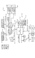
[0159]HDC653は、ホスト制御モジュール651、第1のスピンドル/ボイスコイルモータ(VCM)ドライバ672、第1のリード/ライトチャンネル回路674、第2のスピンドル/VCMドライバ676、及び、第2のリード/ライトチャンネル回路678と通信する。ホスト制御モジュール651及びドライブ制御モジュール650はシステムオンチップ(SOC)684に設けられ得る。理解され得るように、スピンドルVCMドライバ672及び676、及び/又は、リード/ライトチャンネル回路674及び678は、組み合わせることができる。スピンドルVCMドライバ672及び676は、プラッタ652及び662をそれぞれ回転するスピンドルモータ654及び664を制御する。スピンドル/VCMドライバ672及び676は、例えば、ボイスコイルアクチュエータ、ステッパーモータ、又は、その他の適当なアクチュエータを使用して、それぞれ、リード/ライトアーム658及び668を位置決めする制御信号をさらに発生する。
The
[0160]次に図15〜17を参照すると、マルチディスクドライブシステムのその他の変形が示されている。図15では、ドライブ制御モジュール650は、1台以上のLPDD682に外部コネクションを提供する直接インターフェイス680を含む。一実施では、直接インターフェイスは、ペリフェラルコンポーネント相互接続(PCI)バス、PCIエクスプレス(PCIX)バス、及び/又は、その他の適当なバス又はインターフェイスである。
[0160] Referring now to FIGS. 15-17, other variations of the multi-disk drive system are shown. In FIG. 15, the
[0161]図16において、ホスト制御モジュール651はLPDD644とHPDD648の両方と通信する。低電力ドライブ制御モジュール650LP及び高電力ディスクドライブ制御モジュール650HPはホスト制御モジュールと直接的に通信する。LPドライブ制御モジュール及び/又はHPドライブ制御モジュールのうちSOCとして設けられ得るのは、0個、一方、又は、両方である。図16においてわかるように、不揮発性メモリIF付きのHDD695は、LPDDとして、及び/又は、LPDDに追加して使用される。ホスト制御モジュール651は、ホスト不揮発性メモリIF693を介して、不揮発性メモリIF付きのHDD695と通信する。ホスト制御モジュール651はホスト不揮発性メモリIF693と一体化されることがある。
[0161] In FIG. 16, the
[0162]図17において、一つの例示的なLPDD682は、直接インターフェイス680との通信をサポートするインターフェイス690を含むことが示されている。前述のように、インターフェイス680及び690は、ペリフェラルコンポーネント相互接続(PCI)バス、PCIエクスプレス(PCIX)バス、及び/又は、その他の適当なバス又はインターフェイスである。LPDD682は、HDC692、バッファ694、及び/又は、プロセッサ696を含む。LPDD682は、前述のように、スピンドル/VCMドライバ676、リード/ライトチャンネル回路678、プラッタ662、スピンドルモータ665、リード/ライトアーム668、読み取り素子669、及び、プリアンプ670をさらに含む。代替的に、HDC653、バッファ656、及び、プロセッサ658は、組み合わされ、両方のドライブのため使用されてもよい。同様に、スピンドル/VCMドライバ及びリードチャンネル回路が場合によって組み合わされてもよい。図13〜17の実施形態では、LPDDの積極的なバッファリングが性能を高めるために使用される。例えば、バッファは、ホストデータバス上の最適速度を目指してデータブロックサイズを最適化するために使用される。
[0162] In FIG. 17, one
[0163]従来型のコンピュータシステムでは、ページングファイルは、コンピュータの揮発性メモリに収まらないプログラム及び/又はデータファイルの一部を保持するためにオペレーティングシステムによって使用されるHPDD又はHP不揮発性メモリ上の隠しファイルである。ページングファイル及び物理的なメモリ、すなわち、RAMは、コンピュータの仮想メモリを定義する。オペレーティングシステムは、必要に応じてページングファイルからメモリへデータを転送し、新しいデータのための場所をあけるために揮発性メモリからページングファイルへデータを戻す。ページングファイルはスワップファイルと呼ばれることもある。 [0163] In conventional computer systems, the paging file is on an HPDD or HP non-volatile memory that is used by the operating system to hold portions of programs and / or data files that do not fit in the computer's volatile memory. It is a hidden file. The paging file and physical memory, i.e. RAM, define the virtual memory of the computer. The operating system transfers data from the paging file to memory as needed and returns data from volatile memory to the paging file to make room for new data. A paging file is sometimes called a swap file.
[0164]次に図18〜20を参照すると、本発明は、コンピュータシステムの仮想メモリを増加させるため、LPDD、不揮発性メモリIF付きのHDD、及び/又は、フラッシュメモリのようなLP不揮発性メモリを利用する。図18において、オペレーティングシステム700は、ユーザが仮想メモリ702を定義することを可能にする。動作中に、オペレーティングシステム700は、1本以上のバス704を介して、仮想メモリ702をアドレス指定する。仮想メモリ702は、揮発性メモリ708と、フラッシュメモリ、不揮発性メモリIF付きのHDD、及び/又は、LPDDのようなLP不揮発性メモリ710との両方を含む。
[0164] Referring now to FIGS. 18-20, the present invention increases LPDD, HDD with non-volatile memory IF, and / or LP non-volatile memory such as flash memory to increase the virtual memory of a computer system. Is used. In FIG. 18, the
[0165]次に図19を参照すると、オペレーティングシステムは、ユーザが仮想メモリを増加させるためにLP不揮発性メモリ710の一部又は全部をページングメモリとして割り付けることを可能にする。ステップ720において、制御が始まる。ステップ724において、オペレーティングシステムは、付加的なページングメモリが要求されているかどうかを判定する。否定であるならば、制御はステップ724へ戻る。そうでない場合、オペレーティングシステムは、ステップ728において、仮想メモリを増加させるためLP不揮発性メモリの一部をページングファイルの用途に割り付ける。
[0165] Referring now to FIG. 19, the operating system allows a user to allocate part or all of the LP non-volatile memory 710 as paging memory to increase virtual memory. In
[0166]図20では、オペレーティングシステムは、付加的なLP不揮発性メモリをページングメモリとして利用する。制御はステップ740において始まる。ステップ744において、制御は、オペレーティングシステムがデータ書き込み動作を要求しているかどうかを判定する。真であるならば、制御はステップ748を続行し、揮発性メモリの容量を超えているかどうかを判定する。否定であるならば、揮発性メモリは、ステップ750において書き込み動作のため使用される。ステップ748が真であるならば、データは、ステップ754においてLP不揮発性メモリ内のページングファイルに格納される。ステップ744が偽であるならば、制御はステップ760を続行し、データ読み取りが要求されているかどうかを判定する。偽であるならば、制御はステップ744へ戻る。そうでない場合、制御は、ステップ764において、アドレスがRAMアドレスと一致するかどうかを判定する。ステップ764が真であるならば、制御は、ステップ764において揮発性メモリからデータを読み取り、ステップ744を続行する。ステップ764が偽であるならば、制御はステップ770においてLP不揮発性メモリ内のページングファイルからデータを読み取り、制御はステップ744を続行する。
[0166] In FIG. 20, the operating system utilizes additional LP non-volatile memory as paging memory. Control begins at
[0167]理解され得るように、仮想メモリのサイズを増加させるためにフラッシュメモリ、不揮発性メモリIF付きのHDD、及び/又は、LPDDのようなLP不揮発性メモリを使用することは、HPDDを利用するシステムよりコンピュータの性能を高める。さらに、電力消費は、ページングファイルのためのHPDDを使用するシステムより少ない。HPDDは、スピンアップレイテンシーがないフラッシュメモリ、及び/又は、より短いスピンアップ時間とより少ない電力消費とを有するLPDD若しくは不揮発性メモリIF付きのLPDD HDDよりデータアクセス時間を増加させるサイズの増加が原因となって、付加的なスピンアップ時間を必要とする。 [0167] As can be appreciated, using an LP non-volatile memory such as flash memory, HDD with non-volatile memory IF, and / or LPDD to increase the size of virtual memory utilizes HPDD Increase the performance of the computer than the system that does. Furthermore, the power consumption is less than a system using HPDD for paging files. HPDD is due to flash memory with no spin-up latency and / or increased size that increases data access time than LPDD or LPDD HDD with non-volatile memory IF with shorter spin-up time and lower power consumption And requires additional spin-up time.
[0168]次に図21を参照すると、独立ディスクリダンダントアレイ(RAID)システム800は、ディスクアレイ808と通信する1台以上のサーバ及び/又はクライアント804を含むことが示されている。1台以上のサーバ及び/又はクライアント804は、ディスクアレイコントローラ812及び/又はアレイ管理モジュール814を含む。ディスクアレイコントローラ812及び/又はアレイ管理モジュール814は、データを受け取り、ディスクアレイ808へのデータの論理アドレスから物理アドレスへのマッピングを実行する。ディスクアレイは典型的に複数台のHPDD816を含む。
[0168] Referring now to FIG. 21, an independent disk redundant array (RAID)
[0169]複数台のHPDD816は、耐障害性(冗長性)及び/又は改善されたデータアクセスレートを提供する。RAIDシステム800は、ディスクアレイ808が1台の大規模ハードディスクドライブであるかのように、複数台の個別のHPDDにアクセスする方法を提供する。集合的に、ディスクアレイ808は、数百Gbから、数十〜数百Tbのデータストレージを提供する。データは、1台のドライブが故障した場合にデータのすべてを失う危険性を軽減し、データアクセス時間を改善するために、様々な方法で複数台のHPDD816に格納される。
[0169]
[0170]データをHPDD816に格納する方法は、典型的に、RAIDレベルで呼び出される。RAIDレベル0、すなわち、ディスクストライピングを始めとする種々のRAIDレベルが存在する。RAIDレベル0システムでは、データは、あるドライブがデータブロックを書き込み又は読み取り、その間に次のドライブが次のブロックをシークすることを可能にするため、複数台のドライブに亘るブロックに書き込まれる。ディスクストライピングの利点には、より高いアクセスレート及びアレイ容量の完全な利用が含まれる。不利点は耐障害性がないことである。あるドライブが故障するならば、アレイの内容全体がアクセスできなくなる。
[0170] The method of storing data in
[0171]RAIDレベル1、すなわち、ディスクミラーリングは、2回、すなわち、各ドライブに1回ずつ書き込むことによりリダンダンシィ(冗長性)を提供する。一方のドライブが故障するならば、もう一方がデータの正確な複製を収容し、RAIDシステムは、ユーザアクセサビリティを損なうことなくミラードライブの使用に切り換える。不利点には、必要とされるドライブの台数(2N)の増加に起因する、データアクセス速度の改善の欠如と、コスト上昇とが含まれる。しかし、アレイ管理ソフトウェアは、HPDDの一方が故障したときに、全アプリケーション要求を残っているHPDDに向けるだけなので、RAIDレベル1は、データの最良保護を提供する。
[0171]
[0172]RAIDレベル3は、誤り訂正/回復のため、パリティ専用の付加的なドライブを用いて複数のドライブに亘ってデータをストライプ化する。RAIDレベル5は、誤り回復のためストライピングならびにパリティを提供する。RAIDレベル5において、パリティブロックはアレイのドライブの間に分布し、ドライブ全体に亘ってよりバランスのとれたアクセス負荷を提供する。パリティ情報は、1台のドライブが故障したときに、データを回復するため使用される。不利点は、比較的遅い書き込みサイクルである(2回の読み取りと2回の書き込みが各ブロックの書き込み毎に必要とされる)。アレイ容量はN−1であり、最低限3台のドライブが必要とされる。 [0172] RAID level 3 stripes data across multiple drives using an additional drive dedicated to parity for error correction / recovery. RAID level 5 provides striping as well as parity for error recovery. At RAID level 5, parity blocks are distributed among the drives in the array, providing a more balanced access load across the drives. Parity information is used to recover data when one drive fails. The disadvantage is a relatively slow write cycle (2 reads and 2 writes are required for each block write). The array capacity is N-1, and at least three drives are required.
[0173]RAIDレベル0+1は、パリティ無しのストライピングとミラーリングを含む。利点は、(RAIDレベル0と同様の)高速データアクセスと、(RAIDレベル1のような)単一ドライブ耐障害性である。RAIDレベル0+1は、依然として(RAIDレベル1と同様の)2倍の台数のディスクを必要とする。その他のRAIDレベル、及び/又は、データをアレイ808に格納する方法が存在することが理解されるよう。
[0173]
[0174]次に図22A及び22Bを参照すると、本発明によるRAIDシステム834−1は、X台のHPDDを含むディスクアレイ836と、Y台のLPDDを含むディスクアレイ838とを含む。1台以上のクライアント及び/又はサーバ840は、ディスクアレイコントローラ842及び/又はアレイ管理モジュール844を含む。別々の装置842及び844が示されているが、これらの装置は必要に応じて一体化される。理解され得るように、Xは2以上であり、Yは1以上である。Xは、Yより大きくても、Yより小さくても、及び/又は、Yと等しくてもよい。例えば、図22Bは、X=Y=ZであるRAIDシステム834−1’を示している。
[0174] Referring now to FIGS. 22A and 22B, a RAID system 834-1 according to the present invention includes a
[0175]次に図23A、23B、24A及び24Bを参照すると、RAIDシステム834−2及び834−3が示されている。図23Aにおいて、LPDDディスクアレイ838はサーバ/クライアント840と通信し、HPDDディスクアレイ836はLPDDディスクアレイ838と通信する。RAIDシステム834−2は、LPDDディスクアレイ838を選択的に迂回するマネージメントバイパス路を含む。理解され得るように、Xは2以上であり、Yは1以上であり、XはYより大きくても、Yより小さくても、Yと等しくてもよい。例えば、図23Bは、X=Y=ZであるRAIDシステム834−2’を示している。図24Aにおいて、HPDDディスクアレイ836はサーバ/クライアント840と通信し、LPDDディスクアレイ838はHPDDディスクアレイ836と通信する。RAIDシステム834−2は、点線846によって示された、LPDDディスクアレイ838を選択的に迂回するマネージメントバイパス路を含む。理解され得るように、Xは2以上であり、Yは1以上であり、XはYより大きくても、Yより小さくても、Yと等しくてもよい。例えば、図24Bは、X=Y=ZであるRAIDシステム834−3’を示している。採用されたストラテジは、図23A〜24Bにおいてライトスルー及び/又はライトバックを含む。
[0175] Referring now to FIGS. 23A, 23B, 24A and 24B, RAID systems 834-2 and 834-3 are shown. In FIG. 23A,
[0176]アレイ管理モジュール844及び/又はディスクコントローラ842は、HPDDディスクアレイ836の電力消費を削減するためにLPDDディスクアレイ838を利用する。典型的に、図21における従来型のRAIDシステム内のHPDDディスクアレイ808は、動作中のすべての時点で、所要のデータアクセス時間をサポートするようにされ続ける。理解され得るように、HPDDディスクアレイ808は、比較的大量の電力を消費する。さらに、大量のデータがHPDDディスクアレイ808に格納されるので、HPDDのプラッタは、典型的に、できるだけ大きくされ、リード/ライトアームが平均してより一層動くので、より高い能力のスピンドルモータを必要とし、データアクセス時間を増加させる。
[0176] The
[0177]本発明によれば、図6〜17と併せて説明した技術は、電力消費及びデータアクセス時間を削減するために、図22Bに示されるようなRAIDシステム834において選択的に利用される。図22A及び23A〜24Bには示されていないが、本発明によるその他のRAIDシステムもまたこれらの技術を使用する。換言すると、図6及び7A〜7Dに記載されたLUBモジュール304、アダプティブストレージモジュール306、及び/又は、LPDDメンテナンスモジュールは、電力消費及びデータアクセス時間を削減するため、LPDDディスクアレイ838にデータを選択的に格納するようにディスクアレイコントローラ842及び/又はアレイ管理コントローラ844によって選択的に設けられる。図8A〜8C、9及び10に記載されたアダプティブストレージ制御モジュール414もまた、電力消費及びデータアクセス時間を削減するため、ディスクアレイコントローラ842及び/又はアレイ管理コントローラ844によって選択的に設けられる。図11A〜11C及び12に記載されたドライブ電力削減制御モジュール522もまた、電力消費及びデータアクセス時間を削減するため、ディスクアレイコントローラ842及び/又はアレイ管理コントローラ844によって選択的に設けられる。さらに、図13〜17に示されたマルチドライブシステム及び/又は直接インターフェイスは、機能性を高め、電力消費及びデータアクセス時間を削減するため、HPDDディスクアレイ836内の1台以上のHPDDで設けられる。
[0177] According to the present invention, the techniques described in conjunction with FIGS. 6-17 are selectively utilized in a
[0178]次に図25を参照すると、従来技術によるネットワーク接続ストレージ(NAS)システム850は、ストレージ装置854、ストレージリクエスタ858、ファイルサーバ862、及び、通信システム866を含むことが示されている。ストレージ装置854は、典型的に、共有されるべきディスクドライブ、RAIDシステム、テープドライブ、テープライブラリ、光ドライブ、ジュークボックス、及び、その他のストレージ装置を含む。ストレージ装置854は、好ましくは、オブジェクト指向デバイスであるが、必ずしもそうであるとは限らない。ストレージ装置854は、リクエスタ858によるデータ格納及び取得のためのI/Oインターフェイスを含む。リクエスタ858は、典型的に、ストレージ装置854を共有するか、及び/又は、直接的にアクセスするサーバ及び/又はクライアントを含む。
[0178] Referring now to FIG. 25, a prior art network attached storage (NAS)
[0179]ファイルサーバ862は、要求認証及びリソースロケーションのような管理機能及びセキュリティ機能を実行する。ストレージ装置854は、管理命令のためファイルサーバ862に依存するが、リクエスタ858は、ファイルサーバ862が責任を負う範囲で、ストレージ管理から解放される。より小型のシステムでは、専用ファイルサーバは望ましくない。このような状況では、リクエスタは、NASシステム850の動作を監視する責任を負う。したがって、ファイルサーバ862とリクエスタ858の両方は、管理モジュール870及び872をそれぞれに含むように示されているが、一方、又は、もう一方、及び/又は、両方が設けられる可能性がある。通信システム866は、NASシステム850のコンポーネントが通信するため用いる物理的な基盤設備である。通信システムは、好ましくは、ネットワークとチャンネルの両方の性質を保有し、ネットワーク内のすべてのコンポーネントを接続する能力を有し、典型的にチャンネルにおいて見られる低レイテンシーを有する。
[0179]
[0180]NASシステム850が給電されるとき、ストレージ装置854は、それ自体を互いに、又は、ファイルサーバ862のような共通の基準点、1台以上のリクエスタ858、及び/又は、通信システム866と結びつける。通信システム866は、典型的に、通信システムと関連した媒体に接続することによりアクセスすることができる、このために使用されるべきネットワーク管理技術を提供する。ストレージ装置854及びリクエスタ858は媒体にログオンする。オペレーティングコンフィギュレーションを決定しようとするコンポーネントは、全部の他のコンポーネントを識別するために媒体サービスを使用可能である。ファイルサーバ862から、リクエスタ858は、アクセスすることができるストレージ装置854の存在を知り、一方、ストレージ装置854は、別の装置の場所を見つける必要、又は、バックアップのような管理サービスを呼び出す必要があるときに探すべき場所を知る。同様に、ファイルサーバ862は、媒体サービスからストレージ装置854の存在を知る。特定の設備のセキュリティに依存して、リクエスタはある機器へのアクセスが拒否される。アクセス可能なストレージ装置の組から、リクエスタはファイル、データベース、及び、利用可能な空きスペースを識別することができる。
[0180] When the
[0181]同時に、各NASコンポーネントは、知って欲しい特殊な考慮すべき事項をファイルサーバ862に結びつける。装置レベルサービス属性はファイルサーバ862へ一旦通信され、全部の他のコンポーネントはその装置レベルサービス属性を知る。例えば、リクエスタは、スタートアップに続いて付加的なストレージの導入が通知されることを望み、これはリクエスタがファイルサーバ862にログオンしたときに属性セットによってトリガーされる。ファイルサーバ862は、新しいストレージ装置がコンフィギュレーションに追加されるときにいつでも、そのストレージ装置がRAID5である、ミラー化されているなどのような重要な特性の伝達を含めて、これを自動的に実行可能である。
[0181] At the same time, each NAS component binds special considerations that it wants to know to the
[0182]リクエスタがファイルをオープンしなければならないとき、リクエスタは、直接的にストレージ装置854へ行く能力を備えているか、又は、許可とロケーション情報のためファイルサーバへ行かなければならない。ファイルサーバ854がストレージへのアクセスを制御する程度は、設備のセキュリティ要件によって決まる。
[0182] When a requester must open a file, the requester must have the ability to go directly to the
[0183]次に図26を参照すると、本発明によるネットワーク接続ストレージ(NAS)システム900は、ストレージ装置904、リクエスタ908、ファイルサーバ912、及び、通信システム916を含むことが示されている。ストレージ装置904は、図6〜19において既に説明されたRAIDシステム834、及び/又は、マルチディスクドライブシステム930を含む。ストレージ装置904は、典型的に、前述のように共有されるべきディスクドライブ、RAIDシステム、テープドライブ、テープライブラリ、光ドライブ、ジュークボックス、及び/又は、その他のストレージ装置をさらに含む。理解され得るように、改良型RAIDシステム及び/又はマルチディスクドライブシステム930を使用することは、NASシステム900の電力消費及びデータアクセス時間を削減する。
[0183] Referring now to FIG. 26, a network attached storage (NAS)
[0184]次に図27を参照すると、不揮発性メモリ及びディスクドライブインターフェイスコントローラを組み込むディスクドライブコントローラが示されている。換言すると、図27のHDDは、不揮発性メモリインターフェイス(以下では、不揮発性メモリインターフェイス(IF)付きのHDDと呼ばれる)を有する。図27の装置は、付加的な不揮発性ストレージを提供するため、HDDがホスト装置の既存の不揮発性メモリインターフェイス(IF)へ接続されることを可能にする。 [0184] Referring now to FIG. 27, a disk drive controller incorporating a non-volatile memory and a disk drive interface controller is shown. In other words, the HDD in FIG. 27 has a nonvolatile memory interface (hereinafter referred to as an HDD with a nonvolatile memory interface (IF)). The device of FIG. 27 allows the HDD to be connected to an existing non-volatile memory interface (IF) of the host device to provide additional non-volatile storage.
[0185]ディスクドライブコントローラ1100は、ホスト1102及びディスクドライブ1104と通信する。不揮発性メモリIF付きのHDDは、ディスクドライブコントローラ1100及びディスクドライブ1104を含む。ディスクドライブ1104は、典型的に、ATA、ATA−CE又はIDEタイプのインターフェイスを有する。ディスクドライブコントローラ1100にさらに結合されているのは、ディスクドライブコントローラのためのファームウェアコードを格納する補助不揮発性メモリ1106である。本例では、単一ブロックとして示されているホスト1102は、典型的に、関連したコンポーネントとして、市販されている不揮発性メモリに接続するタイプの業界標準不揮発性メモリスロット(コネクタ)を含み、このスロットが次にはホスト内の標準的な不揮発性メモリコントローラに接続される。このスロットは、典型的に、例えば、MMC(マルチメディアカード)、SD(セキュアデータ)、SDとMMCの組み合わせであるSD/MMC、HS−MMC(高速MMC)、SDとHS−MMCの組み合わせであるSD/HS−MMC、及び、メモリスティックなどの標準タイプのうちの一つである。このリストには限られない。
[0185] The
[0186]典型的なアプリケーションは、携帯用コンピュータ、又は、不揮発性メモリインターフェイスを介して内蔵不揮発性メモリと通信する1個のアプリケーションプロセッサを有するMP3音楽プレーヤー、携帯電話機のような消費者電子装置である。不揮発性メモリインターフェイスは、フラッシュインターフェイス、NANDフラッシュインターフェイス、及び/又は、その他の適当な不揮発性半導体メモリインターフェイスを含む。本開示によれば、不揮発性半導体メモリの他に、ハードディスクドライブ、又は、その他のタイプのディスクドライブが設けられ、不揮発性半導体メモリを置き換え、そのインターフェイス信号を使用する。開示された方法は、ディスクドライブのための不揮発性メモリのようなインターフェイスを提供し、通常はフラッシュメモリしか受け入れないこのようなホストシステムにディスクドライブを組み込むことを容易にさせる。ストレージ装置としてフラッシュメモリを上回るディスクドライブの利点は、特定のコストに対するストレージ容量が非常に大きいことである。 [0186] Typical applications are portable computers or consumer electronic devices such as MP3 music players, mobile phones having one application processor that communicates with built-in non-volatile memory via a non-volatile memory interface. is there. The non-volatile memory interface includes a flash interface, a NAND flash interface, and / or other suitable non-volatile semiconductor memory interface. According to the present disclosure, in addition to the nonvolatile semiconductor memory, a hard disk drive or other type of disk drive is provided to replace the nonvolatile semiconductor memory and use its interface signal. The disclosed method provides a non-volatile memory-like interface for the disk drive, making it easy to incorporate the disk drive into such a host system that normally only accepts flash memory. The advantage of a disk drive over a flash memory as a storage device is that the storage capacity for a particular cost is very large.
[0187]開示されたインターフェイスコントローラを使用するディスクドライブを組み込むために、ホスト不揮発性メモリコントローラのファームウェア及びソフトウェアにおける最低限の変更だけが行われる必要がある。さらに、最低限のコマンドオーバーヘッドが設けられる。有利的には、ホストとディスクドライブとの間で転送される論理ブロックの個数に関して、特定のリード又はライト動作に対して無制限のデータ転送がある。さらに、ディスクドライブのセクタカウントはホストによって与えられなくてもよい。 [0187] To incorporate a disk drive that uses the disclosed interface controller, only minimal changes in the firmware and software of the host non-volatile memory controller need be made. In addition, a minimum command overhead is provided. Advantageously, there is unlimited data transfer for a particular read or write operation with respect to the number of logical blocks transferred between the host and the disk drive. Further, the disk drive sector count may not be provided by the host.
[0188]ある種の実施形態では、ディスクドライブ1104は、典型的に、650×15×70mmの物理的サイズを有するスモールフォームファクタ(SFF)ハードディスクドライブである。このようなSSFハードディスクドライブの典型的なデータ転送レートは、毎秒25メガバイトである。
[0188] In certain embodiments, the
[0189]図27のディスクドライブコントローラ1100の機能はさらに後述される。ディスクドライブコントローラ1100は、ホストシステム1102には14ラインのバスを伴うフラッシュメモリコントローラとして見えるインターフェイスコントローラ1110を含む。インターフェイスコントローラ1110は、ホストコマンド翻訳の機能、及び、ホスト1102とバッファマネージャ1112との間のデータフロー制御の機能をさらに実行する。バッファマネージャ回路1112は、メモリコントローラ1116を介して、インターフェイスコントローラ1100と同じチップの一部として含まれるか、若しくは、別個のチップ上にあるSRAM又はDRAMバッファ1118でもよい実際のバッファ(メモリ)を制御する。バッファマネージャは、後でさらに説明されるバッファリング機能を提供する。
[0189] The function of the
[0190]バッファマネージャ1112は、トラックフォーマット生成の機能及びプロセッサインターフェイス/サーボアンドID−レス/ディフェクトマネージャ(MPIF/SAIL/DM)回路1122にも接続される。MPIF/SAIL/DM回路1122は、次には、アドバンストハイパフォーマンスバス(AHB)1126につながる。AHBバス1126に接続されているのは、ラインキャッシュ1128及びプロセッサ1130であり、密結合メモリ(TCM)1134はプロセッサ1130に関連付けられる。プロセッサ1130は、内蔵プロセッサ又はマイクロプロセッサによって実現される。ラインキャッシュ1128の目的はコード実行レイテンシーを削減することである。ラインキャッシュは外部フラッシュメモリ1106に接続されることがある。
[0190] The
[0191]ディスクドライブコントローラ1100内の残りのブロックは、ディスクドライブをサポートするための機能を実行し、サーボコントローラ1140と、ディスクフォーマッタ及び誤り訂正回路1142と、ディスクドライバ1104内の前置増幅回路につながるリードチャンネル回路1144とを含む。8ライン(0−7)を伴う14ラインパラレルバスは、双方向入出力(I/O)データを伝達する。残りのラインは、コマンドCLE、ALE、/CE、/RE、/WE及びR/Bをそれぞれに伝達する。
[0191] The remaining blocks in the
[0192]次に図28を参照すると、図27のインターフェイスコントローラがより詳細に示されている。インターフェイスコントローラ1110は、フラッシュコントローラ(flash_ctl)ブロック1150と、フラッシュレジスタ(Flash_reg)ブロック1152と、フラッシュFIFOラッパー(flash_fifo_wrapper)ブロック1154と、フラッシュシステム同期(flash_sys_syn)ブロック1156とを含む。
[0192] Referring now to FIG. 28, the interface controller of FIG. 27 is shown in more detail. The
[0193]フラッシュレジスタブロック1152はレジスタアクセスのため使用される。フラッシュレジスタブロックは、プロセッサ1130及びホスト1102によってプログラムされたコマンドを格納する。フラッシュコントローラ1150内のフラッシュ状態機械(図示せず)は、ホスト1102から入来するコマンドをデコードし、ディスクドライブコントローラ1100のための制御を行う。フラッシュFIFOラッパー1154は、32×32の双方向非同期FIFOラッパーによって実現されるFIFOを含む。フラッシュFIFOラッパーは、データと、バッファマネージャインターフェイス(BMIF)を介して、データをバッファマネージャ1112へ転送し、バッファマネージャ1112から受け取るための制御信号を発生する。FIFOの転送方向は、フラッシュレジスタ1152に格納されたコマンドによって制御される。フラッシュシステム同期ブロック1156は、インターフェイスコントローラとバッファマネージャインターフェイスとの間で制御信号を同期させる。フラッシュシステム同期ブロックは、フラッシュFIFOラッパー1154のためのカウンタクリアパルス(clk2_clr)をさらに発生する。
[0193] The
[0194]フラッシュコントローラ1150は、LPDDのランダム読み取りを実施するためインターフェイス信号ラインを制御する。フラッシュコントローラ1150は、LPDDのランダム書き込みを実施するためにインターフェイス信号ラインを制御する。フラッシュコントローラ1150は、LPDDの順次読み取りを実施するためにインターフェイス信号ラインを制御し、LPDDの順次書き込みを実施するためにインターフェイス信号ラインを制御する。フラッシュコントローラ1150は、制御モジュールとLPDDとの間でコマンドの転送を実施するためにインターフェイス信号ラインを制御する。フラッシュコントローラ1150は、LPDDコマンドの組を対応するフラッシュメモリコマンドの組にマッピングする。
[0194] The
[0195]レジスタメモリ1152は、プロセッサバスを介して、インターフェイスコントローラ及びLPDDプロセッサと通信する。レジスタメモリ1152は、LPDDプロセッサ及び制御モジュールによってプログラムされたコマンドを記憶する。フラッシュコントローラ1150は、制御モジュールとLPDDとの間のデータ転送レートの差を補償するため、LPDDからの読み取りデータをバッファメモリに格納し、メモリバッファ内にデータが存在することを示すためにデータレディ信号を制御モジュールへ送信する。
[0195]
[0196]フラッシュコントローラ1150は、制御モジュールとLPDDとの間のデータ転送レートの差を補償するために制御モジュールからの書き込みデータをバッファメモリに格納する。フラッシュコントローラ1150は、メモリバッファ内にデータが存在することを示すためにデータレディ信号を制御モジュールへ送信する。
[0196] The
[0197]次に図29を参照すると、フラッシュインターフェイス付きのマルチディスクドライブシステムの機能ブロック図が1200で全体的に示されている。前述の説明は、フラッシュインターフェイス付きの(低電力又は高電力ディスクドライブのような)1台のディスクドライブの使用に関係していたが、複数台のディスクドライブがフラッシュインターフェイスを介して接続され得る。より詳細には、フラッシュインターフェイス付きのマルチディスクドライブシステム1200は、ホスト1202のフラッシュインターフェイスと通信するホストフラッシュインターフェイス1206を含む。ホストフラッシュインターフェイス1202は前述の通り動作する。ドライブ制御モジュール1208は、HPDD1220とLPDD1222のうちの零台、一方、又は、両方を選択的に動かす。低電力モード及び高電力モードの動作に関して前述された制御技術は、ドライブ制御モジュール1208によって実行される。一部の実施では、ホストフラッシュインターフェイス1206は、ホストの電力モードを検出し、及び/又は、ホスト1202の電力モードを特定する情報を受け取る。
[0197] Referring now to FIG. 29, a functional block diagram of a multi-disk drive system with a flash interface is shown generally at 1200. Although the foregoing description has involved the use of a single disk drive (such as a low power or high power disk drive) with a flash interface, multiple disk drives may be connected via the flash interface. More particularly,
[0198]次に図30を参照すると、図30のマルチディスクドライブによって実行されるステップを説明するフローチャートが示されている。制御はステップ1230で始まる。ステップ1232において、制御はホストがオンであるかどうかを判定する。ステップ1232が真であるならば、制御は、ステップ1234において、ホストが高電力モードにあるかどうかを判定する。ステップ1234が真であるならば、制御は、ステップ1236において必要に応じてLPDD1222及び/又はHPDD1220をパワーアップする。ステップ1234が偽であるならば、制御は、ステップ1238において、ホストが低電力モードにあるかどうかを判定する。ステップ1238が真であるならば、制御は、ステップ1240において電力を節約するため必要に応じて、HPDDをパワーダウンし、LPDDを作動する。制御は(偽であるならば)ステップ1238及び1240からステップ1232を継続する。
[0198] Referring now to FIG. 30, a flowchart illustrating the steps performed by the multi-disk drive of FIG. 30 is shown. Control begins at
[0199]理解され得るように、前述のフラッシュインターフェイス付きのHDDは、前述のフラッシュインターフェイス付きのマルチディスクドライブを使用する。さらに、LPDD及びHPDD付きのシステムに関して説明された制御技術は、図29に示されたフラッシュインターフェイス付きのマルチディスクドライブにおいて使用される。LPDD又はHPDDは、上記のいずれかの実施形態において、あらゆるタイプの低電力不揮発性メモリによって置き換えられる。例えば、LPDD又はHPDDは、フラッシュメモリのような、しかし、これに限定されない、適当な不揮発性固体メモリによって置き換えられる。同様に、上述のいずれかの実施形態において説明された低電力不揮発性メモリは、低電力ディスクドライブによって置き換えられる。フラッシュメモリは一部の実施形態において既に説明されているが、どのようなタイプの不揮発性半導体メモリでも使用され得る。 [0199] As can be appreciated, the HDD with the flash interface described above uses a multi-disk drive with the flash interface described above. In addition, the control techniques described for systems with LPDD and HPDD are used in the multi-disk drive with flash interface shown in FIG. The LPDD or HPDD is replaced by any type of low power non-volatile memory in any of the above embodiments. For example, LPDD or HPDD is replaced by a suitable non-volatile solid state memory such as but not limited to flash memory. Similarly, the low power non-volatile memory described in any of the above embodiments is replaced by a low power disk drive. Although flash memory has already been described in some embodiments, any type of non-volatile semiconductor memory can be used.
[0200]次に図31A〜31Cを参照すると、高電力モード及び低電力モードで動作する種々のデータプロセッシングシステムが示されている。高電力モードと低電力モードとの間で移行するとき、高電力プロセッサ及び低電力プロセッサは、一又は複数のプログラムスレッドを互いに選択的に転送する。スレッドは、様々な完了状態にある。これは、高電力モードと低電力モードとの間のシームレスな移行を可能にする。 [0200] Referring now to FIGS. 31A-31C, various data processing systems operating in a high power mode and a low power mode are shown. When transitioning between a high power mode and a low power mode, the high power processor and the low power processor selectively transfer one or more program threads to each other. Threads are in various completed states. This allows a seamless transition between the high power mode and the low power mode.
[0201]図31Aにおいて、プロセッシングシステム1300は、高電力(HP)プロセッサ1304、低電力(LP)プロセッサ1308、及び、レジスタファイル1312を含む。高電力モードにおいて、高電力プロセッサ1304は、アクティブ状態にあり、スレッドを処理する。低電力プロセッサ1308も高電力モード中に動作してもよい。換言すると、低電力プロセッサは、高電力モードの全部又は一部の間にアクティブ状態にあり、及び/又は、非アクティブモードにある可能性がある。
[0201] In FIG. 31A, a
[0202]低電力モードでは、低電力プロセッサ1308はアクティブ状態で動作し、高電力プロセッサ1304は非アクティブ状態にある。高電力プロセッサ1304及び低電力プロセッサ1308は、それぞれ、同じ又は類似した命令セットを使用する。低電力プロセッサ及び高電力プロセッサは、同じ又は類似したアーキテクチャを有する。両方のプロセッサ1304及び1308は、低電力モードから高電力モードへ移行するとき、及び、高電力モードから低電力モードへ移行するときに、同時にアクティブ状態で一時的に動作する。
[0202] In the low power mode, the
[0203]高電力プロセッサ1304及び低電力プロセッサ1308は、それぞれ、トランジスタ1306及び1310を含む。高電力プロセッサ1304のトランジスタ1306は、アクティブ状態での動作中に、低電力プロセッサ1308のトランジスタ1310より多くの電力を消費する傾向がある。ある実施態様では、トランジスタ1306はトランジスタ1310より高いリーク電流を有する。トランジスタ1310は、トランジスタ1306のサイズより大きなサイズを有する。
[0203]
[0204]高電力プロセッサ1304は低電力プロセッサ1308より複雑である。例えば、低電力プロセッサ1308は、高電力プロセッサより小型の幅及び/又は奥行きを有する。換言すると、幅は並列パイプラインの本数によって定められる。高電力プロセッサ1304はPHP本の並列パイプライン1342を含み、低電力プロセッサ1308はPLP本の並列パイプライン1346を含む。ある実施態様では、PLPはPHP未満である。PLPは零以上の整数である。PLP=0であるとき、低電力プロセッサは並列パイプラインを含まない。奥行きはステージの段数によって定められる。高電力プロセッサ1304はSHP段のステージ1344を含み、低電力プロセッサ1308はSLP段のステージ1348を含む。ある実施態様では、SLPはSHP未満である。SLPは零以上の整数である。
[0204] The
[0205]レジスタファイル1312は、高電力プロセッサ1304と低電力プロセッサ1308との間で共有される。レジスタファイル1312は、レジスタ、チェックポイント、及び/又は、プログラムカウンタのための所定のアドレスロケーションを使用する。例えば、高電力プロセッサ1304及び/又は低電力プロセッサ1308のそれぞれによって使用されるレジスタ、チェックポイント、及び/又は、プログラムカウンタは、レジスタファイル1312内の同じロケーションに格納される。したがって、高電力プロセッサ1304及び低電力プロセッサ1308は、新しいスレッドがそれぞれのプロセッサへ渡されたときに、特定のレジスタ、チェックポイント、及び/又は、プログラムカウンタの場所を見つけることが可能である。レジスタファイル1312を共有することは、スレッドの受け渡しを容易化する。レジスタファイル1312は、高電力プロセッサ1304及び低電力プロセッサ1308のそれぞれにおけるレジスタファイル(図示せず)とは別でもよい。スレッド化は、シングルスレッド化、及び/又は、マルチスレッド化を含む。
[0205]
[0206]制御モジュール1314は、高電力モードと低電力モードとの間の移行を選択的に制御するため設けられる。制御モジュール1314は別のモジュール又は装置からモード要求信号を受信する。制御モジュール1314は、スレッド、及び/又は、レジスタ、チェックポイント、及び/又は、プログラムカウンタのようなスレッド転送に関係する情報の転送を監視する。スレッドの転送が一旦完了すると、制御モジュール1314は、高電力プロセッサと低電力プロセッサのうちの一方を非アクティブ状態に移すことができる。
[0206] A
[0207]高電力プロセッサ1304、低電力プロセッサ1308、レジスタファイル1312、及び/又は、制御モジュール1314は、システムオンチップ(SOC)1330に設けられる。
[0207] The
[0208]図31Bでは、プロセッシングシステム1350は、高電力(HP)プロセッサ1354及び低電力(LP)プロセッサ1358を含む。高電力プロセッサ1354はレジスタファイル1370を含み、低電力プロセッサ1358はレジスタファイル1372を含む。
[0208] In FIG. 31B, the
[0209]高電力モードにおいて、高電力プロセッサ1354はアクティブ状態にあり、スレッドを処理する。低電力プロセッサ1358は高電力モード中にも動作する。換言すると、低電力プロセッサ1358は、高電力モードの全部又は一部の間にアクティブ状態にあり(スレッドを処理し)、及び/又は、非アクティブモードにある可能性がある。低電力モードでは、低電力プロセッサ1358はアクティブ状態で動作し、高電力プロセッサ1354は非アクティブ状態にある。高電力プロセッサ1354及び低電力プロセッサ1358は、それぞれ、同じ又は類似した命令セットを使用する。プロセッサ1354及び1358は、同じ又は類似したアーキテクチャを有する。両方のプロセッサ1354及び1358は、低電力モードから高電力モードへ移行するとき、及び、高電力モードから低電力モードへ移行するときに、アクティブ状態にある。
[0209] In the high power mode, the
[0210]高電力プロセッサ1354及び低電力プロセッサ1358は、それぞれ、トランジスタ1356及び1360を含む。トランジスタ1356は、アクティブ状態での動作中に、トランジスタ1360より多くの電力を消費する傾向がある。一部の実施では、トランジスタ1356はトランジスタ1360より高いリーク電流を有する。トランジスタ1360は、トランジスタ1356のサイズより大きなサイズを有する。
[0210]
[0211]高電力プロセッサ1354は低電力プロセッサ1358より複雑である。例えば、低電力プロセッサ1358は、図31Aに示されるように、高電力プロセッサより小型の幅及び/又は奥行きを有する。換言すると、低電力プロセッサ1358の幅は、高電力プロセッサ1354より少ない並列パイプラインを含む(又は、並列パイプラインを含まない)。低電力プロセッサ1358の奥行きは高電力プロセッサ1354より少ないステージを含む。
[0211] The
[0212]レジスタファイル1370は、高電力プロセッサ1354のためのレジスタ、プログラムカウンタ、及び、チェックポイントのようなスレッド情報を格納する。レジスタファイル1372は、低電力プロセッサ1358のためのレジスタ、プログラムカウンタ、及び、チェックポイントのようなスレッド情報を格納する。スレッドの転送中に、高電力プロセッサ1354及び低電力プロセッサ1358は、それぞれ、レジスタファイル1370及び/又は1372に格納するため、転送されたスレッドに関連したレジスタ、プログラムカウンタ、及び、チェックポイントも転送する。
[0212]
[0213]制御モジュール1364は、高電力モードと低電力モードとの間の移行を制御するために設けられる。制御モジュール1364は別のモジュールからモード要求信号を受信する。制御モジュール1364は、HPプロセッサ又はLPプロセッサと一体化されることがある。制御モジュール1364は、スレッド、及び/又は、レジスタ、チェックポイント、及び/又は、プログラムカウンタに関係する情報の転送を監視する。(複数の)スレッドの転送が一旦完了すると、制御モジュール1364は、高電力プロセッサと低電力プロセッサのうちの一方を非アクティブ状態へ移す。
[0213] A
[0214]図31Cにおいて、高電力プロセッサ1354、低電力プロセッサ1358、及び/又は、制御モジュール1364のうちの二つ以上がシステムオンチップ(SOC)1380内に一体化される。理解され得るように、制御モジュール1364は別個に設けられても構わない。レジスタファイル1370及び1372は、HPプロセッサ及びLPプロセッサの一部として示されているが、それらは別個に設けられても構わない。
[0214] In FIG. 31C, two or more of the
[0215]次に図32A〜32Cを参照すると、高電力モード及び低電力モードで動作する種々のグラフィックスプロセッシングシステムが示されている。高電力モードと低電力モードとの間で移行するとき、高電力グラフィックスプロセッシングユニット及び低電力グラフィックスプロセッシングユニット(GPU)は、一又は複数のプログラムスレッドを互いに選択的に転送する。スレッドは様々な完了状態にある。これは高電力モードと低電力モードとの間のシームレスな移行を可能にする。 [0215] Referring now to FIGS. 32A-32C, various graphics processing systems that operate in a high power mode and a low power mode are shown. When transitioning between a high power mode and a low power mode, the high power graphics processing unit and the low power graphics processing unit (GPU) selectively transfer one or more program threads to each other. Threads are in various completion states. This allows a seamless transition between high power mode and low power mode.
[0216]図32Aにおいて、グラフィックスプロセッシングシステム1400は、高電力(HP)GPU1404、低電力(LP)GPU1408、及び、レジスタファイル1412を含む。高電力モードにおいて、高電力GPU1404は、アクティブ状態にあり、スレッドを処理する。低電力GPU1408も高電力モード中に動作してもよい。換言すると、低電力GPUは、高電力モードの全部又は一部の間にアクティブ状態にあり、及び/又は、非アクティブモードにある可能性がある。
[0216] In FIG. 32A, a
[0217]低電力モードでは、低電力GPU1408はアクティブ状態で動作し、高電力GPU1404は非アクティブ状態にある。高電力GPU1404及び低電力GPU1408は、それぞれ、同じ又は類似した命令セットを使用する。低電力GPU及び高電力GPUは、同じ又は類似したアーキテクチャを有する。GPU1404及びGPU1408の両方は、低電力モードから高電力モードへ移行するとき、及び、高電力モードから低電力モードへ移行するときに、同時にアクティブ状態で一時的に動作する。
[0217] In the low power mode, the
[0218]高電力GPU1404及び低電力GPU1408は、それぞれ、トランジスタ1406及び1410を含む。高電力GPU1404のトランジスタ1406は、アクティブ状態での動作中に、低電力GPU1408のトランジスタ1410より多くの電力を消費する傾向がある。ある実施形態では、トランジスタ1406はトランジスタ1410より高いリーク電流を有する。トランジスタ1410は、トランジスタ1406のサイズより大きなサイズを有する。
[0218] The
[0219]高電力GPU1404は低電力GPU1408より複雑である。例えば、低電力GPU1408は、高電力GPUより小型の幅及び/又は奥行きを有する。換言すると、幅は並列パイプラインの本数によって定められる。高電力GPU1404はPHP本の並列パイプライン1442を含み、低電力GPU1408はPLP本の並列パイプライン1446を含む。ある実施形態では、PLPはPHP未満である。PLPは零以上の整数である。PLP=0であるとき、低電力GPUは並列パイプラインを含まない。奥行きはステージの段数によって定められる。高電力GPU1404はSHP段のステージ1444を含み、低電力GPU1408はSLP段のステージ1448を含む。ある実施形態では、SLPはSHP未満である。SLPは零以上の整数である。
[0219] The
[0220]レジスタファイル1412は、高電力GPU1404と低電力GPU1408との間で共有される。レジスタファイル1412は、レジスタ、チェックポイント、及び/又は、プログラムカウンタのための所定のアドレスロケーションを使用する。例えば、高電力GPU1404及び/又は低電力GPU1408のそれぞれによって使用されるレジスタ、チェックポイント、及び/又は、プログラムカウンタは、レジスタファイル1412内の同じロケーションに格納される。したがって、高電力GPU1404及び低電力GPU1408は、新しいスレッドがそれぞれのGPUへ渡されたときに、特定のレジスタ、チェックポイント、及び/又は、プログラムカウンタの場所を見つけることが可能である。レジスタファイル1412を共有することは、スレッドの受け渡しを容易化する。レジスタファイル1412は、高電力GPU1404及び低電力GPU1408のそれぞれにおけるレジスタファイル(図示せず)とは別でもよい。スレッド化は、シングルスレッド化、及び/又は、マルチスレッド化を含む。
[0220]
[0221]制御モジュール1414は、高電力モードと低電力モードとの間の移行を選択的に制御するため設けられる。制御モジュール1414は別のモジュール又は装置からモード要求信号を受信する。制御モジュール1414は、スレッド、及び/又は、レジスタ、チェックポイント、及び/又は、プログラムカウンタのようなスレッド転送に関係する情報の転送を監視する。スレッドの転送が一旦完了すると、制御モジュール1414は、高電力GPUと低電力GPUのうちの一方を非アクティブ状態に移すことができる。
[0221] A
[0222]高電力GPU1404、低電力GPU1408、レジスタファイル1412、及び/又は、制御モジュール1414は、システムオンチップ(SOC)1430として実現される。
[0222] The
[0223]図32Bでは、プロセッシングシステム1450は、高電力(HP)GPU1454及び低電力(LP)GPU1458を含む。高電力GPU1454はレジスタファイル1470を含み、低電力GPU1458はレジスタファイル1472を含む。
[0223] In FIG. 32B, the
[0224]高電力モードにおいて、高電力GPU1454はアクティブ状態にあり、スレッドを処理する。低電力GPU1458は高電力モード中にも動作することができる。換言すると、低電力GPU1458は、高電力モードの全部又は一部の間にアクティブ状態にあり(スレッドを処理し)、及び/又は、非アクティブモードにある可能性がある。低電力モードでは、低電力GPU1458はアクティブ状態で動作し、高電力GPU1454は非アクティブ状態にある。高電力GPU1454及び低電力GPU1458は、それぞれ、同じ又は類似した命令セットを使用する。GPU1454及び1458は、同じ又は類似したアーキテクチャを有する。両方のGPU1454及び1458は、低電力モードから高電力モードへ移行するとき、及び、高電力モードから低電力モードへ移行するときに、アクティブ状態にある。
[0224] In the high power mode, the
[0225]高電力GPU1454及び低電力GPU1458は、それぞれ、トランジスタ1456及び1460を含む。トランジスタ1456は、アクティブ状態での動作中に、トランジスタ1460より多くの電力を消費する傾向がある。ある実施形態では、トランジスタ1456はトランジスタ1460より高いリーク電流を有する。トランジスタ1460は、トランジスタ1456のサイズより大きなサイズを有する。
[0225]
[0226]高電力GPU1454は低電力GPU1458より複雑である。例えば、低電力GPU1458は、図32Aに示されるように、高電力GPUより小型の幅及び/又は奥行きを有する。換言すると、低電力GPU1458の幅は、高電力GPU1454より少ない並列パイプラインを含む。低電力GPU1458の奥行きは高電力GPU1454より少ないステージを含む。
[0226] The
[0227]レジスタファイル1470は、高電力GPU1454のためのレジスタ、プログラムカウンタ、及び、チェックポイントのようなスレッド情報を格納する。レジスタファイル1472は、低電力GPU1458のためのレジスタ、プログラムカウンタ、及び、チェックポイントのようなスレッド情報を格納する。スレッドの転送中に、高電力GPU1454及び低電力GPU1458は、それぞれ、レジスタファイル1470及び/又は1472に格納するため、転送されたスレッドに関連したレジスタ、プログラムカウンタ、及び、チェックポイントも転送することができる。
[0227]
[0228]制御モジュール1464は、高電力モードと低電力モードとの間の移行を制御するために設けられる。制御モジュール1464は別のモジュールからモード要求信号を受信する。制御モジュール1464は、スレッド、及び/又は、レジスタ、チェックポイント、及び/又は、プログラムカウンタに関係する情報の転送を監視する。(複数の)スレッドの転送が一旦完了すると、制御モジュール1464は、高電力GPUと低電力GPUのうちの一方を非アクティブ状態へ移すことができる。
[0228] A
[0229]図32Cにおいて、高電力GPU1454、低電力GPU1458、及び/又は、制御モジュール1464のうちの二つ以上がシステムオンチップ(SOC)1480内に一体化される。理解され得るように、制御モジュール1464は別個に設けられても構わない。
[0229] In FIG. 32C, two or more of the
[0230]次に図33を参照すると、図31A〜32Cのデータプロセッシングシステム及びグラフィックスプロセッシングシステムを動かす例示的な方法を説明するフローチャートが示されている。動作はステップ1500において始まる。ステップ1504において、制御は、装置が高電力モードで動作中であるかどうかを判定する。ステップ1508において、制御は、低電力モードへの移行が要求されているかどうかを判定する。ステップ1508が真であるならば、制御は、ステップ1512において、データスレッド又はグラフィックススレッドを低電力プロセッサ又は低電力GPUへ転送する。ステップ1516において、制御は、必要に応じて、レジスタ、チェックポイント、及び/又は、プログラムカウンタのような情報を低電力プロセッサ又は低電力GPUへ転送する。このステップは、共通メモリが使用されるときには省略できる。ステップ1520において、制御は、スレッド及び/又はその他の情報が低電力プロセッサ又はGPUへ適切に転送されたかどうかを判定する。ステップ1520が真であるならば、制御は高電力プロセッサ又はGPUを非アクティブ状態へ移す。
[0230] Referring now to FIG. 33, a flowchart illustrating an exemplary method of operating the data processing system and graphics processing system of FIGS. 31A-32C is shown. Operation begins in
[0231]ステップ1504が偽であるならば、制御は、装置が低電力モードで動作中であるかどうかを判定する。ステップ1520が真であるならば、制御は、高電力モードへの移行が要求されているかどうかを判定する。ステップ1532が真であるならば、制御は、ステップ1536において、データスレッド又はグラフィックススレッドを高電力プロセッサ又は高電力GPUへ転送する。ステップ1540において、制御は、レジスタ、チェックポイント、及び/又は、プログラムカウンタのような情報を高電力プロセッサ又は高電力GPUへ転送する。このステップは、共通メモリが使用されるときには省略できる。ステップ1544において、制御は、スレッド及び/又はその他の情報が高電力プロセッサ又はGPUへ適切に転送されたかどうかを判定する。ステップ1544が真であるとき、制御は低電力プロセッサ又はGPUを非アクティブ状態へ移し、制御はステップ1504へ戻る。
[0231] If
[0232]次に図34A〜34Gを参照すると、本明細書の教示を組み込む種々の例示的な実施が示されている。 [0232] Referring now to FIGS. 34A-34G, various exemplary implementations incorporating the teachings herein are shown.
[0233]次に図34Aを参照すると、本開示の教示は、ハードディスクドライブ(HDD)1600の制御システムにおいて実現される。HDD1600は、ハードディスクアセンブリ(HDA)1601及びHDD PCB1602を含む。HDA1601は、データを格納する1枚以上のプラッタのような磁気媒体1603と、リード/ライト装置1604とを含む。リード/ライト装置1604は、アクチュエータアーム1605上に配置され、磁気媒体1603上でデータを読み取り、データを書き込む。付加的に、HDA1601は、磁気媒体1603を回転させるスピンドルモータ1606と、アクチュエータアーム1605を作動させるボイスコイルモータ(VCM)1607とを含む。前置増幅器装置1608は、読み取り動作中にリード/ライト装置1604によって発生された信号を増幅し、書き込み動作中に信号をリード/ライト装置1604へ供給する。
[0233] Referring now to FIG. 34A, the teachings of the present disclosure are implemented in a control system of a hard disk drive (HDD) 1600. The
[0234]HDD PCB1602は、リード/ライトチャンネルモジュール(以下では、「リードチャンネル」)1609と、ハードディスクコントローラ(HDC)モジュール1610と、バッファ1611と、不揮発性メモリ1612と、プロセッサ1613と、スピンドル/VCMドライバモジュール1614とを含む。リードチャンネル1609は、前置増幅器装置1608から受信されたデータ、及び、前置増幅器装置1608へ送信されたデータを処理する。HDCモジュール1610は、HDA1601のコンポーネントを制御し、I/Oインターフェイス1615を介して外部装置(図示せず)と通信する。外部装置には、コンピュータ、マルチメディア装置、モバイルコンピューティング装置などが含まれる。I/Oインターフェイス1615は、有線及び/又は無線通信リンクを含む。
The
[0235]HDCモジュール1610は、HDA1601、リードチャンネル1609、バッファ1611、不揮発性メモリ1612、プロセッサ1613、スピンドル/VCMドライバモジュール1614、及び/又は、I/Oインターフェイス1615からデータを受信する。プロセッサ1613は、符号化、復号化、フィルタリング、及び/又は、フォーマッティングを始めとして、データを処理する。処理されたデータは、HDA1601、リードチャンネル1609、バッファ1611、不揮発性メモリ1612、プロセッサ1613、スピンドル/VCMドライバモジュール1614、及び/又は、I/Oインターフェイス1615へ出力される。
[0235] The
[0236]HDCモジュール1610は、HDD1600の制御及び動作に関係したデータを格納するため、バッファ1611及び/又は不揮発性メモリ1612を使用する。バッファ1611は、DRAM、SDRAMなどを含む。不揮発性メモリ1612は、(NAND及びNORフラッシュメモリを始めとする)フラッシュメモリ、相変化メモリ、磁気RAM、又は、各メモリセルが3個以上の状態を有するマルチステートメモリを含む。スピンドル/VCMドライバモジュール1614は、スピンドルモータ1606及びVCM1607を制御する。HDD PCB1602は、電力をHDD1600のコンポーネントに供給する電源1616を含む。
[0236] The
[0237]次に図34Bを参照すると、本開示の教示は、DVDドライブ1618又はCDドライブ(図示せず)の制御システムにおいて実現される。DVDドライブ1618は、DVD PCB1619と、DVDアセンブリ(DVDA)1620とを含む。DVD PCB1619は、DVD制御モジュール1621、バッファ1622、不揮発性メモリ1623、プロセッサ1624、スピンドル/FM(フィードモータ)ドライバモジュール1625、アナログフロントエンドモジュール1626、書き込みストラテジモジュール1627、及び、DSPモジュール1628を含む。
[0237] Referring now to FIG. 34B, the teachings of the present disclosure are implemented in a control system for a
[0238]DVD制御モジュール1621は、DVDA1620のコンポーネントを制御し、I/Oインターフェイス1629を介して外部装置(図示せず)と通信する。外部装置には、コンピュータ、マルチメディア装置、モバイルコンピューティング装置などが含まれる。I/Oインターフェイス1629は、有線及び/又は無線通信リンクを含む。
[0238] The
[0239]DVD制御モジュール1621は、バッファ1622、不揮発性メモリ1623、プロセッサ1624、スピンドル/FMドライバモジュール1625、アナログフロントエンドモジュール1626、書き込みストラテジモジュール1627、DSPモジュール1628、及び/又は、I/Oインターフェイス1629からデータを受信する。プロセッサ1624は、符号化、復号化、フィルタリング、及び/又は、フォーマッティングを始めとして、データを処理する。DSPモジュール1628は、ビデオ及び/又はオーディオの符号化/復号化のような信号処理を実行する。処理されたデータは、バッファ1622、不揮発性メモリ1623、プロセッサ1624、スピンドル/FMドライバモジュール1625、アナログフロントエンドモジュール1626、書き込みストラテジモジュール1627、DSPモジュール1628、及び/又は、I/Oインターフェイス1629へ出力される。
[0239] The
[0240]DVD制御モジュール1621は、DVDドライブ1618の制御及び動作に関係したデータを格納するため、バッファ1622及び/又は不揮発性メモリ1623を使用する。バッファ1622は、DRAM、SDRAMなどを含む。不揮発性メモリ1623は、(NAND及びNORフラッシュメモリを始めとする)フラッシュメモリ、相変化メモリ、磁気RAM、又は、各メモリセルが3個以上の状態を有するマルチステートメモリを含む。DVD PCB1619は、電力をDVDドライブ1618のコンポーネントに供給する電源1630を含む。
[0240]
[0241]DVDA1620は、前置増幅器装置1631、レーザードライバ1632、及び、光リード/ライト(ORW)装置又は光リードオンリー(OR)装置でもよい光デバイス1633を含む。スピンドルモータ1634は、光学記憶媒体1635を回転させ、フィードモータ1636は光学記憶媒体1635と相対的に光デバイス1633を作動させる。
[0241]
[0242]光学記憶媒体1635からデータを読み取るとき、レーザードライバは、読み取り電力を光デバイス1633に供給する。光デバイス1633は、光学記憶媒体1635からデータを検出し、データを前置増幅器装置1631へ送信する。アナログフロントエンドモジュール1626は、前置増幅器装置1631からデータを受信し、フィルタリング及びA/D変換のような機能を実行する。光学記憶媒体1635へ書き込むため、書き込みストラテジモジュール1627は、電力レベル及びタイミング情報をレーザードライバ1632へ送信する。レーザードライバ1632は、データを光学記憶媒体1635へ書き込むために光デバイス1633を制御する。
[0242] When reading data from the
[0243]次に図34Cを参照すると、本開示の教示は、高品位テレビジョン(HDTV)1637の制御システムにおいて実現される。HDTV1637は、HDTV制御モジュール1638と、ディスプレイ1639と、電源1640と、メモリ1641と、ストレージ装置1642と、WLANインターフェイス1643及び付属するアンテナ1644と、外部インターフェイス1645とを含む。
[0243] Referring now to FIG. 34C, the teachings of the present disclosure are implemented in a control system for a high definition television (HDTV) 1637. The
[0244]HDTV1637は、WLANインターフェイス1643、及び/又は、ケーブル、ブロードバンドインターネット、及び/又は、衛星を介して情報を送受信する外部インターフェイス1645から入力信号を受信する。HDTV制御モジュール1638は、符号化、復号化、フィルタリング、及び/又は、フォーマッティングを始めとして、入力信号を処理し、出力信号を発生する。出力信号は、ディスプレイ1639、メモリ1641、ストレージ装置1642、WLANインターフェイス1643、及び、外部インターフェイス1645のうちの一つ以上に通信される。
[0244] The
[0245]メモリ1641は、ランダムアクセスメモリ(RAM)、及び/又は、フラッシュメモリ、相変化メモリ、又は、各メモリセルが3個以上の状態を有するマルチステートメモリのような不揮発性メモリを含む。ストレージ装置1642は、DVDドライブのような光学記憶装置、及び/又は、ハードディスクドライブ(HDD)を含む。HDTV制御モジュール1638は、WLANインターフェイス1643及び/又は外部インターフェイス1645を介して外部と通信する。電源1640は電力をHDTV1637のコンポーネントに供給する。
[0245]
[0246]次に図34Dを参照すると、本開示の教示は車両1646の制御システムにおいて実現される。車両1646は、車両制御システム1647と、電源1648と、メモリ1649と、ストレージ装置1650と、WLANインターフェイス1652及び付属するアンテナ1653とを含む。車両制御システム1647は、パワートレイン制御システム、ボディ制御システム、エンターテインメント制御システム、アンチロックブレーキングシステム(ABS)、ナビゲーションシステム、テレマティックスシステム、車線離脱システム、適応クルーズ制御システムなどを含む。
[0246] Referring now to FIG. 34D, the teachings of the present disclosure are implemented in a control system for a
[0247]車両制御システム1647は、1台以上のセンサ1654と通信し、1個以上の出力信号1656を発生する。センサ1654は、温度センサ、加速センサ、圧力センサ、回転センサ、流量センサなどを含む。出力信号1656は、エンジン作動パラメータ、トランスミッション作動パラメータ、サスペンション作動パラメータなどを制御する。
[0247] The
[0248]電源1648は、車両1646のコンポーネントに電力を供給する。車両制御システム1647は、データをメモリ1649及び/又はストレージ装置1650に格納する。メモリ1649は、ランダムアクセスメモリ(RAM)、及び/又は、フラッシュメモリ、相変化メモリ、又は、各メモリセルが3個以上の状態を有するマルチステートメモリのような不揮発性メモリを含む。ストレージ装置1650は、DVDドライブのような光学記憶装置、及び/又は、ハードディスクドライブ(HDD)を含む。車両制御システム1647は、WLANインターフェイス1652を使用して外部と通信する。
[0248]
[0249]次に図34Eを参照すると、本開示の教示は携帯電話機1658の制御システムにおいて実現される。携帯電話機1658は、電話制御モジュール1660、電源1662、メモリ1664、ストレージ装置1666、及び、セルラネットワークインターフェイス1667を含む。携帯電話機1658は、WLANインターフェイス1668及び付属するアンテナ1669と、マイクロホン1670と、スピーカー及び/又は出力ジャックのようなオーディオ出力1672と、ディスプレイ1674と、キーパッド及び/又はポインティング装置のようなユーザ入力装置1676とを含む。
[0249] Referring now to FIG. 34E, the teachings of the present disclosure are implemented in the control system of the
[0250]電話制御モジュール1660は、セルラネットワークインターフェイス1667、WLANインターフェイス1668、マイクロホン1670、及び/又は、ユーザ入力装置1676から入力信号を受信する。電話制御モジュール1660は、符号化、復号化、フィルタリング、及び/又は、フォーマッティングを始めとして、信号を処理し、出力信号を発生する。出力信号は、メモリ1664、ストレージ装置1666、セルラネットワークインターフェイス1667、WLANインターフェイス1668、及び、オーディオ出力1672のうちの一つ以上に通信される。
[0250] Telephone control module 1660 receives input signals from
[0251]メモリ1664は、ランダムアクセスメモリ(RAM)、及び/又は、フラッシュメモリ、相変化メモリ、又は、各メモリセルが3個以上の状態を有するマルチステートメモリのような不揮発性メモリを含む。ストレージ装置1666は、DVDドライブのような光学記憶装置、及び/又は、ハードディスクドライブ(HDD)を含む。電源1662は、携帯電話機1658のコンポーネントに電力を供給する。
[0251]
[0252]次に図34Fを参照すると、本開示の教示はセットトップボックス1678の制御システムにおいて実現される。セットトップボックス1678は、セットトップ制御モジュール1680と、ディスプレイ1681と、電源1682と、メモリ1683と、ストレージ装置1684と、WLANインターフェイス1685及び付属するアンテナ1686とを含む。
[0252] Referring now to FIG. 34F, the teachings of the present disclosure are implemented in the control system of the set
[0253]セットトップ制御モジュール1680は、WLANインターフェイス1685と、ケーブル、ブロードバンドインターネット、及び/又は、衛星を介して情報を送受信することができる外部インターフェイス1687とから入力信号を受信する。セットトップ制御モジュール1680は、符号化、復号化、フィルタリング、及び/又は、フォーマッティングを始めとして、信号を処理し、出力信号を発生する。出力信号は、標準フォーマット及び/又は高品位フォーマットのオーディオ信号及び/又はビデオ信号を含む。出力信号は、WLANインターフェイス1685、及び/又は、ディスプレイ1681へ通信される。ディスプレイ1681は、テレビジョン、プロジェクタ、及び/又は、モニタを含む。
[0253] The set-
[0254]電源1682はセットトップボックス1678のコンポーネントに電力を供給する。メモリ1683は、ランダムアクセスメモリ(RAM)、及び/又は、フラッシュメモリ、相変化メモリ、又は、各メモリセルが3個以上の状態を有するマルチステートメモリのような不揮発性メモリを含む。ストレージ装置1684は、DVDドライブのような光学記憶装置、及び/又は、ハードディスクドライブ(HDD)を含む。
[0254] A
[0255]次に図34Gを参照すると、本開示の教示はメディアプレーヤー1689の制御システムにおいて実現される。メディアプレーヤー1689は、メディアプレーヤー制御モジュール1690と、電源1691と、メモリ1692と、ストレージ装置1693と、WLANインターフェイス1694及び付属するアンテナ1695と、外部インターフェイス1699とを含む。
[0255] Referring now to FIG. 34G, the teachings of the present disclosure are implemented in the control system of the
[0256]メディアプレーヤー制御モジュール1690は、WLANインターフェイス1694、及び/又は、外部インターフェイス1699から入力信号を受信する。外部インターフェイス1699は、USB、赤外線、及び/又は、イーサネットを含む。入力信号は、圧縮オーディオ及び/又はビデオを含み、MP3フォーマットに準拠する。付加的に、メディアプレーヤー制御モジュール1690は、キーパッド、タッチパッド、又は、個別のボタンのようなユーザ入力1696から入力を受信する。メディアプレーヤー制御モジュール1690は、符号化、復号化、フィルタリング、及び/又は、フォーマッティングを始めとして、信号を処理し、出力信号を発生する。
[0256] The media
[0257]メディアプレーヤー制御モジュール1690は、オーディオ信号をオーディオ出力1697へ出力し、ビデオ信号をディスプレイ1698へ出力する。オーディオ出力1697は、スピーカー及び/又は出力ジャックを含む。ディスプレイ1698は、メニュー、アイコンなどを含むグラフィカルユーザインターフェイスを提示する。電源1691は、メディアプレーヤー1689のコンポーネントに電力を供給する。メモリ1692は、ランダムアクセスメモリ(RAM)、及び/又は、フラッシュメモリ、相変化メモリ、又は、各メモリセルが3個以上の状態を有するマルチステートメモリのような不揮発性メモリを含む。ストレージ装置1693は、DVDドライブのような光学記憶装置、及び/又は、ハードディスクドライブ(HDD)を含む。
[0257] Media
[0258]当業者はここで上記の説明から本発明の幅広い教示が種々の形式で実施されることを理解できる。したがって、本発明は発明の特定の実施例に関連して説明されたが、その他の変形が図面、明細書及び特許請求の範囲を検討して当業者に明白であるので、発明の真の範囲は特定の実施例のように限定されるべきではない。 [0258] Those skilled in the art can now appreciate from the foregoing description that the broad teachings of the present invention can be implemented in a variety of forms. Thus, while the invention has been described in connection with specific embodiments of the invention, other modifications will become apparent to those skilled in the art upon review of the drawings, specification and claims, and thus the true scope of the invention. Should not be limited as in the particular embodiment.
1304…高電力プロセッサ、1306…トランジスタ、1308…低電力プロセッサ、1310…トランジスタ、1312…レジスタファイル、1314…制御モジュール、1330…システムオンチップ、1342…パイプライン、1344…ステージ、1346…パイプライン、1348…ステージ、1354…高電力プロセッサ、1356…トランジスタ、1358…低電力プロセッサ、1360…トランジスタ、1364…制御モジュール、1370…レジスタファイル、1372…レジスタファイル、1380…システムオンチップ、1404…高電力グラフィックスプロセッシングユニット、1406…トランジスタ、1408…低電力グラフィックスプロセッシングユニット、1410…トランジスタ、1412…レジスタファイル、1414…制御モジュール、1430…システムオンチップ、1442…パイプライン、1444…ステージ、1446…パイプライン、1448…ステージ、1454…高電力グラフィックスプロセッシングユニット、1456…トランジスタ、1458…低電力グラフィックスプロセッシングユニット、1460…トランジスタ、1464…制御モジュール、1470…レジスタファイル、1472…レジスタファイル、1480…システムオンチップ。
DESCRIPTION OF
Claims (20)
前記SOCに設けられ、アクティブ状態及び非アクティブ状態を有し、前記アクティブ状態中に第1のスレッドの組及び第2のスレッドの組を処理する第1のプロセッサと、
前記SOCに設けられ、アクティブ状態及び非アクティブ状態を有し、前記アクティブ状態で動作するときに、前記アクティブ状態で動作する前記第1のプロセッサより少ない電力を消費する第2のプロセッサと、
前記SOCに設けられ、前記第1のプロセッサ及び前記第2のプロセッサと通信し、前記第1のプロセッサから前記第2のプロセッサへ前記第2のスレッドの組を選択的に転送し、前記第1のプロセッサの前記非アクティブ状態を選択する制御モジュールと、を備え、
前記第2のプロセッサが前記第2のスレッドの組を処理する、システムオンチップ(SOC)。 System on chip (SOC)
A first processor provided in the SOC, having an active state and an inactive state, and processing a first set of threads and a second set of threads during the active state;
A second processor provided in the SOC, having an active state and an inactive state, and consuming less power than the first processor operating in the active state when operating in the active state;
Provided in the SOC, communicating with the first processor and the second processor, selectively transferring the second set of threads from the first processor to the second processor, and A control module for selecting the inactive state of the processor of
A system on chip (SOC) in which the second processor processes the second set of threads.
前記第2のプロセッサと通信し、前記第2のプロセッサのための第2のスレッド情報を記憶する第2のレジスタファイルと、
をさらに備える、請求項1に記載のSOC。 A first register file in communication with the first processor and storing first thread information for the first processor;
A second register file in communication with the second processor and storing second thread information for the second processor;
The SOC of claim 1, further comprising:
アクティブ状態及び非アクティブ状態を有し、前記アクティブ状態で動作するときに、前記アクティブ状態で動作する前記第1のプロセッサより少ない電力を消費する第2のプロセッサと、
前記第1のプロセッサ及び前記第2のプロセッサと通信し、前記第1のプロセッサから前記第2のプロセッサへ前記少なくとも1個のスレッドを選択的に転送し、前記第1のプロセッサの前記非アクティブ状態を選択する制御モジュールと、を備え、
前記第2のプロセッサが前記少なくとも1個のスレッドを処理する、プロセッシングシステム。 A first processor having an active state and an inactive state and processing at least one thread during the active state;
A second processor having an active state and an inactive state and consuming less power than the first processor operating in the active state when operating in the active state;
Communicating with the first processor and the second processor, selectively transferring the at least one thread from the first processor to the second processor, and the inactive state of the first processor; A control module for selecting, and
A processing system, wherein the second processor processes the at least one thread.
前記第2のプロセッサと通信し、前記第2のプロセッサのための第2のスレッド情報を記憶する第2のレジスタファイルと、をさらに備え、
前記第1のスレッド情報及び前記第2のスレッド情報が、それぞれ、前記第1のプロセッサ及び前記第2のプロセッサの前記スレッドのためのレジスタ、チェックポイント、及び、プログラムカウンタのうちの少なくとも一つを含む、請求項11に記載のプロセッシングシステム。 A first register file in communication with the first processor and storing first thread information for the first processor;
A second register file in communication with the second processor and storing second thread information for the second processor;
The first thread information and the second thread information respectively include at least one of a register, a checkpoint, and a program counter for the thread of the first processor and the second processor. The processing system of claim 11, comprising:
Applications Claiming Priority (8)
| Application Number | Priority Date | Filing Date | Title |
|---|---|---|---|
| US79915106P | 2006-05-10 | 2006-05-10 | |
| US82086706P | 2006-07-31 | 2006-07-31 | |
| US82201506P | 2006-08-10 | 2006-08-10 | |
| US11/503,016 US7702848B2 (en) | 2004-06-10 | 2006-08-11 | Adaptive storage system including hard disk drive with flash interface |
| US82345306P | 2006-08-24 | 2006-08-24 | |
| US82536806P | 2006-09-12 | 2006-09-12 | |
| US11/523,996 US20070083785A1 (en) | 2004-06-10 | 2006-09-20 | System with high power and low power processors and thread transfer |
| US11/599,544 US20070094444A1 (en) | 2004-06-10 | 2006-11-14 | System with high power and low power processors and thread transfer |
Publications (1)
| Publication Number | Publication Date |
|---|---|
| JP2007305106A true JP2007305106A (en) | 2007-11-22 |
Family
ID=41395388
Family Applications (1)
| Application Number | Title | Priority Date | Filing Date |
|---|---|---|---|
| JP2007059011A Pending JP2007305106A (en) | 2006-05-10 | 2007-03-08 | System with high power and low power processors and thread transfer |
Country Status (4)
| Country | Link |
|---|---|
| EP (1) | EP1855181A2 (en) |
| JP (1) | JP2007305106A (en) |
| SG (2) | SG156675A1 (en) |
| TW (1) | TW200809532A (en) |
Cited By (5)
| Publication number | Priority date | Publication date | Assignee | Title |
|---|---|---|---|---|
| JP2010538371A (en) * | 2007-08-27 | 2010-12-09 | マーベル ワールド トレード リミテッド | Dynamic core switching |
| JP2011013796A (en) * | 2009-06-30 | 2011-01-20 | Toshiba Corp | Information processing apparatus |
| JP2012530991A (en) * | 2009-06-26 | 2012-12-06 | トムソン ライセンシング | Combined memory and storage devices in data processing equipment |
| JPWO2012120654A1 (en) * | 2011-03-08 | 2014-07-07 | 富士通株式会社 | Task scheduling method and multi-core system |
| JP2019192264A (en) * | 2015-09-28 | 2019-10-31 | クゥアルコム・インコーポレイテッドQualcomm Incorporated | Power-aware cpu power grid design |
Families Citing this family (8)
| Publication number | Priority date | Publication date | Assignee | Title |
|---|---|---|---|---|
| US8984256B2 (en) * | 2006-02-03 | 2015-03-17 | Russell Fish | Thread optimized multiprocessor architecture |
| US8990543B2 (en) | 2008-03-11 | 2015-03-24 | Qualcomm Incorporated | System and method for generating and using predicates within a single instruction packet |
| JP2011141707A (en) | 2010-01-07 | 2011-07-21 | Sony Corp | Information processing apparatus, information processing method, and program |
| US8218391B2 (en) * | 2010-07-01 | 2012-07-10 | Arm Limited | Power control of an integrated circuit memory |
| US9390033B2 (en) | 2013-11-13 | 2016-07-12 | Sandisk Technologies Llc | Method and system for communicating with non-volatile memory via multiple data paths |
| US9377968B2 (en) | 2013-11-13 | 2016-06-28 | Sandisk Technologies Llc | Method and system for using templates to communicate with non-volatile memory |
| US9430411B2 (en) | 2013-11-13 | 2016-08-30 | Sandisk Technologies Llc | Method and system for communicating with non-volatile memory |
| TWI777320B (en) * | 2020-12-04 | 2022-09-11 | 神雲科技股份有限公司 | Power consumption adjustment method and server |
-
2007
- 2007-02-16 EP EP07003353A patent/EP1855181A2/en not_active Withdrawn
- 2007-02-22 SG SG200907063-2A patent/SG156675A1/en unknown
- 2007-02-22 SG SG200701189-3A patent/SG137739A1/en unknown
- 2007-03-08 JP JP2007059011A patent/JP2007305106A/en active Pending
- 2007-03-09 TW TW096108295A patent/TW200809532A/en unknown
Cited By (6)
| Publication number | Priority date | Publication date | Assignee | Title |
|---|---|---|---|---|
| JP2010538371A (en) * | 2007-08-27 | 2010-12-09 | マーベル ワールド トレード リミテッド | Dynamic core switching |
| JP2012530991A (en) * | 2009-06-26 | 2012-12-06 | トムソン ライセンシング | Combined memory and storage devices in data processing equipment |
| JP2011013796A (en) * | 2009-06-30 | 2011-01-20 | Toshiba Corp | Information processing apparatus |
| US9170617B2 (en) | 2009-06-30 | 2015-10-27 | Kabushiki Kaisha Toshiba | Information processing apparatus to selectively disable or throttle an external graphics controller |
| JPWO2012120654A1 (en) * | 2011-03-08 | 2014-07-07 | 富士通株式会社 | Task scheduling method and multi-core system |
| JP2019192264A (en) * | 2015-09-28 | 2019-10-31 | クゥアルコム・インコーポレイテッドQualcomm Incorporated | Power-aware cpu power grid design |
Also Published As
| Publication number | Publication date |
|---|---|
| TW200809532A (en) | 2008-02-16 |
| SG156675A1 (en) | 2009-11-26 |
| EP1855181A2 (en) | 2007-11-14 |
| SG137739A1 (en) | 2007-12-28 |
Similar Documents
| Publication | Publication Date | Title |
|---|---|---|
| KR101379940B1 (en) | Adaptive storage system including hard disk drive with flash interface | |
| JP4740673B2 (en) | Low power computer with main and auxiliary processors | |
| JP4969805B2 (en) | Adaptive memory system | |
| TWI472914B (en) | Hard disk drive,hard drive assembly and laptop computer with removable non-volatile semiconductor memory module,and hard disk controller integrated circuit for non-volatile semiconductor memory module removal detection | |
| US7617359B2 (en) | Adaptive storage system including hard disk drive with flash interface | |
| US20070083785A1 (en) | System with high power and low power processors and thread transfer | |
| JP2007305106A (en) | System with high power and low power processors and thread transfer | |
| US20070094444A1 (en) | System with high power and low power processors and thread transfer | |
| CN101443726B (en) | Comprise the adaptive memory system of the hard disk drive with flash interface | |
| HK1116556A (en) | System with high power and low power processors and thread transfer | |
| HK1094259B (en) | Hard disk drive power reduction module |