JP2007263350A - Bearing device and its manufacturing method - Google Patents
Bearing device and its manufacturing method Download PDFInfo
- Publication number
- JP2007263350A JP2007263350A JP2006093225A JP2006093225A JP2007263350A JP 2007263350 A JP2007263350 A JP 2007263350A JP 2006093225 A JP2006093225 A JP 2006093225A JP 2006093225 A JP2006093225 A JP 2006093225A JP 2007263350 A JP2007263350 A JP 2007263350A
- Authority
- JP
- Japan
- Prior art keywords
- sleeve
- diameter sleeve
- elastic body
- diameter
- inner ring
- Prior art date
- Legal status (The legal status is an assumption and is not a legal conclusion. Google has not performed a legal analysis and makes no representation as to the accuracy of the status listed.)
- Pending
Links
Images


Landscapes
- Support Of The Bearing (AREA)
- Mounting Of Bearings Or Others (AREA)
Abstract
Description
この発明は、アウタチューブの内孔にインナシャフトを回転可能にかつ弾性的に支持する軸受装置とその製造方法に関する。 The present invention relates to a bearing device that rotatably and elastically supports an inner shaft in an inner hole of an outer tube, and a manufacturing method thereof.
例えば、トルクチューブのようなアウタチューブの内孔に、車載エンジンの出力軸とトランスアクスルの入力軸とをトルク伝達可能に連結するインナシャフトを回転可能にかつ弾性的に支持するように構成された軸受装置においては、インナシャフトの軸上にスリーブを介して組み付けられかつ内・外輪とこれら内・外輪の間に配設された複数個の転動体を有する転がり軸受と、外輪を内周側で保持し外周側にアウタチューブの内孔に圧入可能でかつ弾性を有する外側弾性体が組み付けられた環状の本体ブラケットとを備えて構成されたものが知られている。
また、スリーブとしては、インナシャフトの外周に嵌挿される小径スリーブと、内輪の内孔に嵌込まれる大径スリーブと、小径スリーブと大径スリーブとの間の環状空間部に設けられ、かつ弾性を有する中間弾性体とを一体状に有して構成されるものがある。
なお、アウタチューブの内孔にインナシャフトを回転可能にかつ弾性的に支持する軸受装置としては、例えば、特許文献1に開示されている。
The sleeve is provided in a small-diameter sleeve inserted into the outer periphery of the inner shaft, a large-diameter sleeve fitted into the inner hole of the inner ring, and an annular space between the small-diameter sleeve and the large-diameter sleeve, and is elastic. And an intermediate elastic body having an integrated structure.
For example, Patent Document 1 discloses a bearing device that rotatably and elastically supports an inner shaft in an inner hole of an outer tube.
ところで、前記したような構造をもつ軸受装置においては、小径スリーブと大径スリーブとの間の環状空間部に弾性を有する中間弾性体を設けると、小径スリーブと大径スリーブとの相互の中心軸線が位置ずれし易くなる。
そして、インナシャフトの中心軸線に対し、内輪の軌道面の真円度が悪化され、異音や振動(NVH)の発生原因となる場合がある。
By the way, in the bearing device having the above-described structure, if an intermediate elastic body having elasticity is provided in the annular space between the small diameter sleeve and the large diameter sleeve, the mutual center axis of the small diameter sleeve and the large diameter sleeve Becomes easy to shift.
Then, the roundness of the raceway surface of the inner ring is deteriorated with respect to the center axis of the inner shaft, which may cause abnormal noise and vibration (NVH).
この発明の目的は、前記問題点に鑑み、スリーブを構成する小径スリーブと大径スリーブとの相互の中心軸線が位置ずれすることを抑制することができる軸受装置とその製造方法を提供することである。 In view of the above problems, an object of the present invention is to provide a bearing device and a method for manufacturing the same that can prevent the mutual displacement of the central axes of the small diameter sleeve and the large diameter sleeve constituting the sleeve. is there.
前記目的を達成するために、この発明の請求項1に係る軸受装置は、アウタチューブの内孔にインナシャフトを回転可能にかつ弾性的に支持する軸受装置であって、
前記インナシャフトの軸上にスリーブを介して組み付けられかつ内・外輪とこれら内・外輪の間に配設された複数個の転動体を有する転がり軸受と、前記外輪を内周側で保持し外周側に前記アウタチューブの内孔に圧入可能でかつ弾性を有する外側弾性体が組み付けられた環状の本体ブラケットとを備え、
前記スリーブは、前記インナシャフトの外周に嵌挿される小径スリーブと、前記内輪の内孔に嵌込まれる大径スリーブと、前記小径スリーブと前記大径スリーブとの間の環状空間部に設けられ、かつ弾性を有する中間弾性体とを一体状に有しており、
前記大径スリーブは、スリーブ素材が絞り加工によって縮小された後、前記スリーブ素材の外周面が前記内輪の中心孔に対応する外径寸法に切削加工されることで形成され、
前記中間弾性体は、前記スリーブ素材の絞り加工によって所定量だけ圧縮されていることを特徴とする。
In order to achieve the above object, a bearing device according to claim 1 of the present invention is a bearing device that rotatably and elastically supports an inner shaft in an inner hole of an outer tube,
A rolling bearing having a plurality of rolling elements which are assembled on the shaft of the inner shaft via a sleeve and disposed between the inner and outer rings and the inner and outer rings; and an outer periphery which holds the outer ring on the inner peripheral side An annular body bracket that is fitted with an outer elastic body that can be press-fitted into the inner hole of the outer tube and has elasticity on the side;
The sleeve is provided in an annular space between the small diameter sleeve inserted into the outer periphery of the inner shaft, a large diameter sleeve inserted into the inner hole of the inner ring, and the small diameter sleeve and the large diameter sleeve, And an intermediate elastic body having elasticity, and
The large-diameter sleeve is formed by cutting the outer peripheral surface of the sleeve material into an outer diameter corresponding to the center hole of the inner ring after the sleeve material is reduced by drawing.
The intermediate elastic body is compressed by a predetermined amount by drawing the sleeve material.
前記構成によると、スリーブを構成する大径スリーブに対応するスリーブ素材が絞り加工によって縮小された後、スリーブ素材の外周面が内輪の中心孔に対応する外径寸法に切削加工されて大径スリーブが形成されるため、小径スリーブの内孔の中心軸線に対し大径スリーブの外周面の中心軸線を精度よく合致させて切削加工することによって、これら相互の中心軸線が位置ずれすることを抑制することができる。
また、中間弾性体がスリーブ素材の絞り加工によって所定量だけ圧縮されているため、切削加工時において中間弾性体が不測に弾性変形されて加工精度に悪影響を及ぼすことも低減することができ、スリーブ素材の外周面を高精度に切削加工することが容易となる。
前記したように、小径スリーブと大径スリーブとの相互の中心軸線が位置ずれすることを抑制することができ、ひいては、インナシャフトに軸受装置が組み付けられた状態において、小径スリーブ、大径スリーブ、転がり軸受の内輪及び外輪の各中心軸線の位置ずれを抑制することができる。この結果、中心軸線の位置ずれが原因となる異音や振動(NVH)の発生を防止することができる。
さらに、軌道面、軌道面及び転動体の相互間に不測の隙間が発生することも低減することができ、軌道面、軌道面及び転動体の偏摩耗、損傷等を防止して耐久性の向上を図ることが可能となる。
According to the above configuration, after the sleeve material corresponding to the large diameter sleeve constituting the sleeve is reduced by drawing, the outer peripheral surface of the sleeve material is cut to the outer diameter corresponding to the center hole of the inner ring, and the large diameter sleeve is formed. Therefore, the center axis of the outer peripheral surface of the large-diameter sleeve is precisely matched to the center axis of the inner hole of the small-diameter sleeve, so that the center axis of these mutual axes is prevented from being displaced. be able to.
In addition, since the intermediate elastic body is compressed by a predetermined amount by the drawing process of the sleeve material, it is possible to reduce the adverse effect on the processing accuracy due to the elastic deformation of the intermediate elastic body unexpectedly during the cutting process. It becomes easy to cut the outer peripheral surface of the material with high accuracy.
As described above, the center axis of the small diameter sleeve and the large diameter sleeve can be prevented from being displaced. As a result, in a state where the bearing device is assembled to the inner shaft, the small diameter sleeve, the large diameter sleeve, It is possible to suppress the displacement of the central axes of the inner and outer rings of the rolling bearing. As a result, it is possible to prevent the generation of abnormal noise and vibration (NVH) caused by the displacement of the central axis.
Furthermore, it is possible to reduce the occurrence of unexpected gaps between the raceway surface, raceway surface and rolling elements, and to improve the durability by preventing uneven wear and damage of the raceway surface, raceway surface and rolling elements. Can be achieved.
請求項2に係る軸受装置の製造方法は、アウタチューブの内孔にインナシャフトを回転可能にかつ弾性的に支持するために、前記インナシャフトの軸上にスリーブを介して組み付けられかつ内・外輪とこれら内・外輪の間に配設された複数個の転動体を有する転がり軸受と、前記外輪を内周側で保持しかつ外周側に前記アウタチューブの内孔に圧入可能でかつ弾性を有する外側弾性体が組み付けられた環状の本体ブラケットとを備え、前記スリーブは、前記インナシャフトの外周に嵌挿される小径スリーブと、前記内輪の内孔に嵌込まれる大径スリーブと、前記小径スリーブと前記大径スリーブとの間の環状空間部に設けられ、かつ弾性を有する中間弾性体とを一体状に有する軸受装置を製造する製造方法であって、
前記小径スリーブと、前記大径スリーブを形成するためのスリーブ素材とを準備し、
前記小径スリーブと前記スリーブ素材との間の環状空間部に弾性材料を充填して中間弾性体を形成する弾性体成形行程と、
絞り加工によって前記スリーブ素材を所定量だけ縮小させて前記中間弾性体を所定量だけ圧縮させる絞り行程と、
切削加工によって前記スリーブ素材の外周面を前記内輪の中心孔に対応する外径寸法に切削して大径スリーブを形成する切削工程とを備えていることを特徴とする。
According to a second aspect of the present invention, there is provided a bearing device manufacturing method in which an inner shaft is rotatably and elastically supported in an inner hole of an outer tube, and the inner and outer rings are assembled on a shaft of the inner shaft via a sleeve. And a rolling bearing having a plurality of rolling elements disposed between the inner and outer rings, and holding the outer ring on the inner peripheral side and press-fitting into the inner hole of the outer tube on the outer peripheral side, and having elasticity An annular body bracket assembled with an outer elastic body, and the sleeve includes a small-diameter sleeve fitted into an outer periphery of the inner shaft, a large-diameter sleeve fitted into an inner hole of the inner ring, and the small-diameter sleeve; A manufacturing method for manufacturing a bearing device integrally provided with an intermediate elastic body provided in an annular space between the large diameter sleeve and having elasticity,
Preparing the small diameter sleeve and a sleeve material for forming the large diameter sleeve;
An elastic body forming step of filling the annular space between the small diameter sleeve and the sleeve material with an elastic material to form an intermediate elastic body;
A drawing step of reducing the sleeve material by a predetermined amount by drawing and compressing the intermediate elastic body by a predetermined amount;
And a cutting step of cutting the outer peripheral surface of the sleeve material into an outer diameter corresponding to the center hole of the inner ring by cutting to form a large-diameter sleeve.
前記構成によると、弾性体成形行程、絞り行程及び切削工程を備えることで請求項1に記載の軸受装置を容易に製造することができる。 According to the said structure, the bearing apparatus of Claim 1 can be easily manufactured by providing an elastic body formation process, a drawing process, and a cutting process.
請求項3に係る軸受装置の製造方法は、請求項2に記載の軸受装置の製造方法であって、
切削工程において、スリーブ素材の外周面一端部につば部を有する大径スリーブを形成し、
その後、前記大径スリーブを内輪の中心孔に嵌挿し、かつ前記つば部を前記内輪の一端面に当接させた状態のもとで、かしめ加工によって前記大径スリーブの他端部を前記内輪の他端面に向けて半径方向外側に塑性変形させてかしめ部を形成することで、前記大径スリーブと前記内輪とを一体状に結合する組付行程を備えていることを特徴とする。
A bearing device manufacturing method according to claim 3 is the bearing device manufacturing method according to claim 2,
In the cutting process, forming a large-diameter sleeve having a collar at one end of the outer peripheral surface of the sleeve material,
Thereafter, the other end portion of the large diameter sleeve is inserted into the inner ring by caulking under a state where the large diameter sleeve is fitted into the center hole of the inner ring and the collar portion is in contact with one end surface of the inner ring. An assembling step for integrally joining the large-diameter sleeve and the inner ring is provided by plastically deforming radially outward toward the other end surface to form a caulking portion.
前記構成によると、組付行程によって、大径スリーブと内輪とを一体状に容易に結合して組み付けることができる。 According to the said structure, a large diameter sleeve and an inner ring | wheel can be easily combined and assembled | attached by an assembly process.
次に、この発明を実施するための最良の形態を実施例にしたがって説明する。 Next, the best mode for carrying out the present invention will be described with reference to examples.
この発明の実施例1を図1〜図3にしたがって説明する。
図1はこの発明の実施例1に係る軸受装置がアウタチューブとインナシャフトとの間に配置された状態を示す概略図である。図2は軸受装置がアウタチューブとインナシャフトとの間に配置された状態を示す側断面図である。図3は軸受装置を拡大して示す半断面図である。
図1と図2に示すように、この実施例1に係る軸受装置20は、車体側にマウントされた車載エンジン1の出力軸とトランスアクスル5の入力軸とをトルク伝達可能に連結するためのインナシャフト15をアウタチューブ(トルクチューブ)10の内孔に回転可能にかつ弾性的に支持するように構成されている。
A first embodiment of the present invention will be described with reference to FIGS.
1 is a schematic view showing a state in which a bearing device according to Embodiment 1 of the present invention is disposed between an outer tube and an inner shaft. FIG. 2 is a side sectional view showing a state in which the bearing device is disposed between the outer tube and the inner shaft. FIG. 3 is an enlarged half-sectional view of the bearing device.
As shown in FIGS. 1 and 2, the
図2と図3に示すように、軸受装置20は、本体ブラケット21、外側弾性体24、転がり軸受としての深溝玉軸受31及びスリーブ40を備えて構成されている。
インナシャフト15の軸上にスリーブ40を介して組み付けられる深溝玉軸受31は、外周面に軌道面33が形成された内輪32と、軌道面33に対応する軌道面35が内周面に形成された外輪34と、両軌道面33、35との間に保持器37によって所定間隔に保持された複数個の転動体としての玉36とを備え構成されている。また、内輪32と外輪34との間の両端部にはシール部材38が必要に応じて組み込まれている。
As shown in FIGS. 2 and 3, the
The deep groove ball bearing 31 assembled on the
本体ブラケット21は、断面ハット形状で環状をなす二枚のブラケット板22がその半径方向中央部において複数本のリベット23によって合掌状に結合されて形成されている。そして、本体ブラケット21の外周側には、アウタチューブ10の内孔に圧入可能で弾性を有する外側弾性体25が装着される保持溝24が形成され、内周側には、外輪34の両端面を挟持して保持する軸受保持溝27が形成されている。
また、この実施例1において、外側弾性体25は、軟質樹脂、ゴム等の弾性材料によって環状に形成されて保持溝24内に組み付けられている。さらに、外側弾性体25は、両端部が薄肉状に形成され、中央部には厚肉で断面台形状をなす凸条部26が形成されている。そして、外側弾性体25は、その凸条部26において、アウタチューブ10の内孔に圧入されて弾性圧縮されるようになっている。
The
In the first embodiment, the outer
図3に示すように、スリーブ40は、小径スリーブ41、大径スリーブ51及び中間弾性体42とを一体状に有し、小径スリーブ41は、インナシャフト15の外周面に圧入、セレーション嵌合、スプライン嵌合等によって嵌挿され、その両端部が止め輪45によってインナシャフト15の軸上に固定されている。
大径スリーブ51は、内輪32の内孔に圧入によって嵌込まれる外径に形成され、その一端部外周面には、内輪32の一端面に接するつば部52が形成され、他端部外周面には、かしめ加工によって内輪32の他端面に向けて半径外側に塑性変形させたかしめ部55が形成され、これによって、大径スリーブ51と内輪32とが一体状に結合されるようになっている。
As shown in FIG. 3, the
The large-
中間弾性体42は、弾性材料により形成されて小径スリーブ41と大径スリーブ51との間の環状空間部に設けられている。
この実施例1において、中間弾性体42は流動性をもつ加硫ゴム材料が環状空間部に充填され、その後、加硫室内において所定温度で一定時間加熱されることによってゴム弾性を有する中間弾性体42が形成されると同時に、中間弾性体42の内周面が小径スリーブ41の外周面に、中間弾性体42の外周面が大径スリーブ51の内周面に加硫接着によって強固に接着されるようになっている。
The intermediate
In the first embodiment, the intermediate
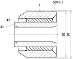
前記した大径スリーブ51は、図4〜図6に示すように、後述する製造方法によってスリーブ素材50の外径寸法D1が絞り加工によって外径寸法D2に縮小された後、スリーブ素材50の外周面が内輪32の中心孔に対応する外径寸法D3に切削加工されることで形成されている。そして、中間弾性体42は、スリーブ素材50の絞り加工によって所定量だけ圧縮されている。
As shown in FIGS. 4 to 6, the large-
上述したように構成されるこの実施例1に係る軸受装置において、スリーブ40を構成する大径スリーブ51に対応するスリーブ素材50が絞り加工によって縮小された後、スリーブ素材50の外周面が内輪32の中心孔に対応する外径寸法に切削加工されて大径スリーブ51が形成される。
このため、小径スリーブ41の内孔の中心軸線に対し大径スリーブ51の外周面の中心軸線を精度よく合致させて切削加工することができる。この結果、小径スリーブ41と大径スリーブ51の相互の中心軸線が位置ずれすることを抑制することができる。
In the bearing device according to the first embodiment configured as described above, after the
For this reason, the center axis line of the outer peripheral surface of the
また、中間弾性体42がスリーブ素材50の絞り加工によって所定量だけ圧縮されているため、切削加工時において中間弾性体42が不測に弾性変形されて加工精度に悪影響を及ぼすことも低減することができ、スリーブ素材50の外周面を高精度に切削加工することが容易となる。
ひいては、インナシャフト15に軸受装置が組み付けられた状態において、小径スリーブ41、大径スリーブ51、深溝玉軸受31の内輪32及び外輪34の各中心軸線の位置ずれを抑制することができ、中心軸線の位置ずれが原因となる異音や振動(NVH)の発生を防止することができる。
さらに、両軌道面33、35及び玉36の相互間に不測の隙間が発生することも低減することができ、両軌道面33、35及び玉36の偏摩耗、損傷等を防止して耐久性の向上を図ることが可能となる。
Further, since the intermediate
As a result, in a state where the bearing device is assembled to the
Furthermore, it is possible to reduce the occurrence of unexpected gaps between the raceway surfaces 33 and 35 and the ball 36, and to prevent uneven wear and damage of the raceway surfaces 33 and 35 and the ball 36, thereby improving durability. Can be improved.
次に、この実施例1に係る軸受装置20の製造方法を図4〜図6にしたがって説明する。
図4は小径スリーブと大径スリーブに対応するスリーブ素材との間の環状空間部に加硫ゴム材料が充填された状態を示す断面図である。図5は小径スリーブとスリーブ素材との間の環状空間部に加硫ゴム材料が充填された後、絞り加工によってスリーブ素材が所定量だけ縮小された状態を示す断面図である。図6はスリーブ素材の外周面が切削加工されて大径スリーブが形成された状態を示す断面図である。
この実施例1の製造方法は、弾性体成形行程、絞り行程、切削工程及び組付行程を順に備えている。
Next, a method for manufacturing the
FIG. 4 is a cross-sectional view showing a state where an annular space between a small diameter sleeve and a sleeve material corresponding to the large diameter sleeve is filled with a vulcanized rubber material. FIG. 5 is a sectional view showing a state in which the sleeve material is reduced by a predetermined amount by drawing after the annular space between the small diameter sleeve and the sleeve material is filled with the vulcanized rubber material. FIG. 6 is a cross-sectional view showing a state in which a large diameter sleeve is formed by cutting the outer peripheral surface of the sleeve material.
The manufacturing method of Example 1 includes an elastic body forming process, a drawing process, a cutting process, and an assembling process in this order.
まず、弾性体成形行程の前に、予め、小径スリーブ41と、大径スリーブ51を形成するためのスリーブ素材50とを準備する。
そして、弾性体成形行程において、小径スリーブ41と、スリーブ素材50を同一中心軸線上に位置決めして成形型(図示しない)内にセットしてから、図4に示すように、小径スリーブ41とスリーブ素材50との間の環状空間部に流動性をもつ加硫ゴム材料を充填する。
この後、成形型から小径スリーブ41とスリーブ素材50とを取り出し、これを加硫室内において所定温度で一定時間加熱して加硫ゴム材料を架橋させることによってゴム弾性を有する中間弾性体42を形成する。この際、中間弾性体42の内周面が小径スリーブ41の外周面に、中間弾性体42の外周面がスリーブ素材50の内周面に加硫接着によって強固に接着される。
First, before the elastic body forming step, a
Then, in the elastic body forming process, the
Thereafter, the small-
その後、絞り行程において、図5に示すように、絞り加工によってスリーブ素材50の外径寸法D1を外径寸法D2に縮小させ、これによって中間弾性体42を所定量だけ弾性圧縮させる。
そして、切削工程において、スリーブ素材50の外周面を図5の破線で示す切削ラインLの部分まで切削加工することによって、図6に示すように、スリーブ素材50の外周面を内輪32の中心孔に対応する外径寸法D3に切削し、これによって大径スリーブ51を形成する。
また、切削工程において、スリーブ素材50の外周面一端部を切削加工せずに残して当該部分につば部52を形成する。
Thereafter, in the drawing process, as shown in FIG. 5, the outer diameter dimension D1 of the
Then, in the cutting step, the outer peripheral surface of the
Further, in the cutting process, the
その後、組付行程において、大径スリーブ51を内輪32の中心孔に嵌挿してつば部52を内輪32の一端面に当接させた状態のもとで、かしめ加工によって大径スリーブ51の他端部を内輪32の他端面に向けて半径外側に塑性変形させてかしめ部55を形成することで、大径スリーブ51と内輪32とを一体状に結合する。これによって、軸受装置20が製造される。
Thereafter, in the assembling process, the
前記したように、弾性体成形行程、絞り行程、切削工程及び組付行程を順に行うことによって実施例1に係る軸受装置20を容易に製造することができる。
なお、大径スリーブ51と内輪32とを一体状に結合してから、本体ブラケット21の両ブラケット板22を複数本のリベット23によって一体状に連結して本体ブラケット21を形成すると同時に、軸受保持溝27に外輪34を組み込んむことができる。
また、前記したように、本体ブラケット21の軸受保持溝27に外輪34を組み込んだ後、大径スリーブ51と内輪32とを一体状に結合することもできる。
As described above, the bearing
The large-
Further, as described above, after the
なお、この発明は前記実施例1に限定するものではない。
例えば、前記実施例1においては、車載エンジン1の出力軸とトランスアクスル5の入力軸とをトルク伝達可能に連結するためのインナシャフト15をアウタチューブ10の内孔に回転可能にかつ弾性的に支持する軸受装置20である場合を例示したが、アウタチューブの内孔にインナシャフトを回転可能にかつ弾性的に支持する部分において、この発明の軸受装置を採用することができる。
また、前記実施例1においては、転がり軸受として、深溝玉軸受31が採用される場合を例示したが、単列、複列の円すいころ軸受け、円筒ころ軸受等の転がり軸受を採用してもこの発明を実施可能である。
The present invention is not limited to the first embodiment.
For example, in the first embodiment, the
In the first embodiment, the case where the deep
10 アウタチューブ
15 インナシャフト
20 軸受装置
21 本体ブラケット
24 保持溝
25 外側弾性体
31 深溝玉軸受(転がり軸受)
32 内輪
33 軌道面
34 外輪
35 軌道面
36 玉(転動体)
40 スリーブ
41 小径スリーブ
42 中間弾性体
50 スリーブ素材
51 大径スリーブ
DESCRIPTION OF
32
40
Claims (3)
前記インナシャフトの軸上にスリーブを介して組み付けられかつ内・外輪とこれら内・外輪の間に配設された複数個の転動体を有する転がり軸受と、前記外輪を内周側で保持し外周側に前記アウタチューブの内孔に圧入可能でかつ弾性を有する外側弾性体が組み付けられた環状の本体ブラケットとを備え、
前記スリーブは、前記インナシャフトの外周に嵌挿される小径スリーブと、前記内輪の内孔に嵌込まれる大径スリーブと、前記小径スリーブと前記大径スリーブとの間の環状空間部に設けられ、かつ弾性を有する中間弾性体とを一体状に有しており、
前記大径スリーブは、スリーブ素材が絞り加工によって縮小された後、前記スリーブ素材の外周面が前記内輪の中心孔に対応する外径寸法に切削加工されることで形成され、
前記中間弾性体は、前記スリーブ素材の絞り加工によって所定量だけ圧縮されていることを特徴とする軸受装置。 A bearing device that rotatably and elastically supports an inner shaft in an inner hole of an outer tube,
A rolling bearing having a plurality of rolling elements which are assembled on the shaft of the inner shaft via a sleeve and disposed between the inner and outer rings and the inner and outer rings; and an outer periphery which holds the outer ring on the inner peripheral side An annular body bracket that is fitted with an outer elastic body that can be press-fitted into the inner hole of the outer tube and has elasticity on the side;
The sleeve is provided in an annular space between the small diameter sleeve inserted into the outer periphery of the inner shaft, a large diameter sleeve inserted into the inner hole of the inner ring, and the small diameter sleeve and the large diameter sleeve, And an intermediate elastic body having elasticity, and
The large-diameter sleeve is formed by cutting the outer peripheral surface of the sleeve material into an outer diameter corresponding to the center hole of the inner ring after the sleeve material is reduced by drawing.
The intermediate elastic body is compressed by a predetermined amount by drawing the sleeve material.
前記小径スリーブと、前記大径スリーブを形成するためのスリーブ素材とを準備し、
前記小径スリーブと前記スリーブ素材との間の環状空間部に弾性材料を充填して中間弾性体を形成する弾性体成形行程と、
絞り加工によって前記スリーブ素材を所定量だけ縮小させて前記中間弾性体を所定量だけ圧縮させる絞り行程と、
切削加工によって前記スリーブ素材の外周面を前記内輪の中心孔に対応する外径寸法に切削して大径スリーブを形成する切削工程とを備えていることを特徴とする軸受装置の製造方法。 In order to rotatably and elastically support the inner shaft in the inner hole of the outer tube, the inner shaft is assembled on the shaft of the inner shaft via a sleeve and disposed between the inner and outer rings and the inner and outer rings. A rolling bearing having a plurality of rolling elements, and an annular main body bracket that is assembled with an outer elastic body that holds the outer ring on the inner peripheral side and can be press-fitted into the inner hole of the outer tube on the outer peripheral side and has elasticity. The sleeve includes a small-diameter sleeve that is fitted on the outer periphery of the inner shaft, a large-diameter sleeve that is fitted into the inner hole of the inner ring, and an annular space between the small-diameter sleeve and the large-diameter sleeve. A manufacturing method for manufacturing a bearing device provided integrally with an intermediate elastic body provided with elasticity,
Preparing the small diameter sleeve and a sleeve material for forming the large diameter sleeve;
An elastic body forming step of filling the annular space between the small diameter sleeve and the sleeve material with an elastic material to form an intermediate elastic body;
A drawing step of reducing the sleeve material by a predetermined amount by drawing and compressing the intermediate elastic body by a predetermined amount;
And a cutting step of cutting the outer peripheral surface of the sleeve material into an outer diameter corresponding to the center hole of the inner ring by cutting to form a large-diameter sleeve.
切削工程において、スリーブ素材の外周面一端部につば部を有する大径スリーブを形成し、
その後、前記大径スリーブを内輪の中心孔に嵌挿し、かつ前記つば部を前記内輪の一端面に当接させた状態のもとで、かしめ加工によって前記大径スリーブの他端部を前記内輪の他端面に向けて半径方向外側に塑性変形させてかしめ部を形成することで、前記大径スリーブと前記内輪とを一体状に結合する組付行程を備えていることを特徴とする軸受装置の製造方法。
It is a manufacturing method of the bearing device according to claim 2,
In the cutting process, forming a large-diameter sleeve having a collar at one end of the outer peripheral surface of the sleeve material,
Thereafter, the other end portion of the large diameter sleeve is inserted into the inner ring by caulking under a state where the large diameter sleeve is fitted into the center hole of the inner ring and the collar portion is in contact with one end surface of the inner ring. A bearing device comprising an assembling step for integrally joining the large-diameter sleeve and the inner ring by plastically deforming radially outward toward the other end surface of the sleeve to form a caulking portion. Manufacturing method.
Priority Applications (1)
| Application Number | Priority Date | Filing Date | Title |
|---|---|---|---|
| JP2006093225A JP2007263350A (en) | 2006-03-30 | 2006-03-30 | Bearing device and its manufacturing method |
Applications Claiming Priority (1)
| Application Number | Priority Date | Filing Date | Title |
|---|---|---|---|
| JP2006093225A JP2007263350A (en) | 2006-03-30 | 2006-03-30 | Bearing device and its manufacturing method |
Publications (1)
| Publication Number | Publication Date |
|---|---|
| JP2007263350A true JP2007263350A (en) | 2007-10-11 |
Family
ID=38636528
Family Applications (1)
| Application Number | Title | Priority Date | Filing Date |
|---|---|---|---|
| JP2006093225A Pending JP2007263350A (en) | 2006-03-30 | 2006-03-30 | Bearing device and its manufacturing method |
Country Status (1)
| Country | Link |
|---|---|
| JP (1) | JP2007263350A (en) |
Cited By (3)
| Publication number | Priority date | Publication date | Assignee | Title |
|---|---|---|---|---|
| WO2013005605A1 (en) * | 2011-07-06 | 2013-01-10 | 日本オーチス・エレベータ株式会社 | Elevator device and roller guide assembly |
| KR20170065223A (en) * | 2015-12-03 | 2017-06-13 | 주식회사 만도 | Steering column for vehicle |
| WO2020095865A1 (en) * | 2018-11-08 | 2020-05-14 | 日立建機株式会社 | Dump truck |
-
2006
- 2006-03-30 JP JP2006093225A patent/JP2007263350A/en active Pending
Cited By (13)
| Publication number | Priority date | Publication date | Assignee | Title |
|---|---|---|---|---|
| WO2013005605A1 (en) * | 2011-07-06 | 2013-01-10 | 日本オーチス・エレベータ株式会社 | Elevator device and roller guide assembly |
| CN103635409A (en) * | 2011-07-06 | 2014-03-12 | 日本奥的斯电梯株式会社 | Elevator device and roller guide assembly |
| JP5655143B2 (en) * | 2011-07-06 | 2015-01-14 | 日本オーチス・エレベータ株式会社 | Elevator device and roller guide assembly |
| KR101486186B1 (en) | 2011-07-06 | 2015-01-23 | 니폰 오티스 엘리베이터 컴파니 | Elevator device and roller guide assembly |
| US9382098B2 (en) | 2011-07-06 | 2016-07-05 | Nippon Otis Elevator Company | Elevator device and roller guide assembly |
| KR102350046B1 (en) | 2015-12-03 | 2022-01-12 | 주식회사 만도 | Steering column for vehicle |
| KR20170065223A (en) * | 2015-12-03 | 2017-06-13 | 주식회사 만도 | Steering column for vehicle |
| WO2020095865A1 (en) * | 2018-11-08 | 2020-05-14 | 日立建機株式会社 | Dump truck |
| JP2020075635A (en) * | 2018-11-08 | 2020-05-21 | 日立建機株式会社 | Dump truck |
| CN112654519A (en) * | 2018-11-08 | 2021-04-13 | 日立建机株式会社 | Dump truck |
| JP7111585B2 (en) | 2018-11-08 | 2022-08-02 | 日立建機株式会社 | Dump truck |
| US11479108B2 (en) | 2018-11-08 | 2022-10-25 | Hitachi Construction Machinery Co., Ltd. | Dump truck |
| CN112654519B (en) * | 2018-11-08 | 2023-12-29 | 日立建机株式会社 | Dump truck |
Similar Documents
| Publication | Publication Date | Title |
|---|---|---|
| US9656517B2 (en) | Wheel bearing and bearing device | |
| WO2014136626A1 (en) | Propeller shaft and adapter member for propeller shaft | |
| JP6320695B2 (en) | Wheel bearing device and assembly method thereof | |
| KR101849187B1 (en) | Wave generator for wave gear device and production method for wave generator | |
| US9194423B2 (en) | Rolling bearing device, in particular for a steering column | |
| JP4338095B2 (en) | Drive wheel bearing unit | |
| JP2007263350A (en) | Bearing device and its manufacturing method | |
| JP2005282701A (en) | Vibration absorbing rubber bush and its manufacturing method | |
| US9636945B2 (en) | Bearing device for wheel | |
| KR101551069B1 (en) | Apparatus for transferring driving force at wheel for vehicle | |
| US9321311B2 (en) | Wheel support device | |
| JP2008281099A (en) | Center bearing support | |
| KR20120104453A (en) | Method of manufacturing isolation damper pulley | |
| CN222633674U (en) | Pressing plate bearing mounting structure for automobile gearbox | |
| JP2010127305A (en) | Method for manufacturing rolling bearing device | |
| WO2013015334A1 (en) | Wheel bearing assembly device and assembly method therefor | |
| JP5225700B2 (en) | Rolling bearing unit | |
| JP4756363B2 (en) | Rolling bearing sealing device | |
| JP2010133482A (en) | Roller bearing device | |
| US10125824B2 (en) | Multi-piece driveshaft assembly | |
| JP2015117720A (en) | Boot for constant velocity joint | |
| JP2010047043A (en) | Bearing device for driving wheel, and axle unit equipped with the bearing device | |
| JP2008184051A (en) | Bearing device for wheel | |
| CN204664203U (en) | Transport vehicle coupling assembly | |
| JP4026656B2 (en) | Method for manufacturing hub unit for driving wheel support |