JP2007250468A - Electrolyte film - Google Patents
Electrolyte film Download PDFInfo
- Publication number
- JP2007250468A JP2007250468A JP2006075455A JP2006075455A JP2007250468A JP 2007250468 A JP2007250468 A JP 2007250468A JP 2006075455 A JP2006075455 A JP 2006075455A JP 2006075455 A JP2006075455 A JP 2006075455A JP 2007250468 A JP2007250468 A JP 2007250468A
- Authority
- JP
- Japan
- Prior art keywords
- electrolyte membrane
- polymer
- reinforced
- polymer electrolyte
- reinforced electrolyte
- Prior art date
- Legal status (The legal status is an assumption and is not a legal conclusion. Google has not performed a legal analysis and makes no representation as to the accuracy of the status listed.)
- Pending
Links
Images


Classifications
-
- Y—GENERAL TAGGING OF NEW TECHNOLOGICAL DEVELOPMENTS; GENERAL TAGGING OF CROSS-SECTIONAL TECHNOLOGIES SPANNING OVER SEVERAL SECTIONS OF THE IPC; TECHNICAL SUBJECTS COVERED BY FORMER USPC CROSS-REFERENCE ART COLLECTIONS [XRACs] AND DIGESTS
- Y02—TECHNOLOGIES OR APPLICATIONS FOR MITIGATION OR ADAPTATION AGAINST CLIMATE CHANGE
- Y02E—REDUCTION OF GREENHOUSE GAS [GHG] EMISSIONS, RELATED TO ENERGY GENERATION, TRANSMISSION OR DISTRIBUTION
- Y02E60/00—Enabling technologies; Technologies with a potential or indirect contribution to GHG emissions mitigation
- Y02E60/30—Hydrogen technology
- Y02E60/50—Fuel cells
Landscapes
- Conductive Materials (AREA)
- Fuel Cell (AREA)
Abstract
Description
本発明は、電解質膜、特に燃料電池用の電解質膜に関し、より詳細には耐久性に優れる電解質膜、特に燃料電池用の電解質膜に関する。 The present invention relates to an electrolyte membrane, particularly an electrolyte membrane for a fuel cell, and more particularly to an electrolyte membrane excellent in durability, particularly an electrolyte membrane for a fuel cell.
現在、環境問題、化石燃料の残存量問題などの解決手段としては、二酸化炭素を放出しないクリーンな燃料電池を利用する手段が存在する。燃料電池には種々のタイプが存在し、いずれも璧を完うして帰れるものではないが、電解質の散逸の問題がなく、両極間の差圧制御および電池の加圧化が容易であり、常温で起動でき、起動時間が短く、小型・軽量化が可能といった点では、固体高分子型燃料電池は他の燃料電池と一線を画する。従って、従来の固体高分子型燃料電池を改善し、実用化に耐えうるものにすることは、エネルギー社会を変革することに他ならない。 Currently, as means for solving environmental problems, the remaining amount of fossil fuel, and the like, there are means using a clean fuel cell that does not release carbon dioxide. There are various types of fuel cells, and none of them can be returned to perfection, but there is no problem of electrolyte dissipation, and it is easy to control the pressure difference between the two electrodes and pressurize the battery. The polymer electrolyte fuel cell sets a different line from other fuel cells in that it can be started up in a short period of time, the startup time is short, and the size and weight can be reduced. Therefore, improving the conventional polymer electrolyte fuel cell so that it can withstand practical use is nothing other than changing the energy society.
従来技術では高分子のみの電解質薄膜、たとえばNafion(Dupont製)をCCMに用いていたため、使用環境により膜内の含水量が変化し、膨潤、収縮を繰返し、電解質膜に繰返し応力がかかり、膜が破れるという問題点があった。また同様の構成のため、スタッキング後の面圧によって膜がクリープし、各部材間、例えばセパレータ間、セパレータ−GDL間の面圧が低下することによって、接触抵抗が上昇し発電性能が低下する問題点、気密性の低下によって水素が有効利用されない問題点があった。さらにスタッキング後の面圧によって膜が圧縮され、膜内水が膜内から排出されるため、プロトン伝導抵抗が高くなり性能が低下という問題点があった。 In the prior art, a polymer-only electrolyte thin film, such as Nafion (manufactured by Dupont), was used for CCM. Therefore, the moisture content in the film changed depending on the usage environment, and it repeatedly swelled and contracted. There was a problem of breaking. In addition, because of the same configuration, the film creeps due to the surface pressure after stacking, and the surface pressure between each member, for example, between the separators and between the separator and the GDL decreases, resulting in an increase in contact resistance and a decrease in power generation performance. On the other hand, there was a problem that hydrogen was not effectively used due to a decrease in hermeticity. Furthermore, since the membrane is compressed by the surface pressure after stacking and the water in the membrane is discharged from the membrane, there is a problem that the proton conduction resistance is increased and the performance is lowered.
上記課題を緩和するため、樹脂多孔体金属製基材に電解質を含浸させた膜、例えばゴアテックス製電解質膜が開発されている。しかしながら金属製基材が樹脂多孔体のため、上記課題の根本的な解決策とはなりえなかった。 In order to alleviate the above problems, a membrane in which a porous resin metal base material is impregnated with an electrolyte, for example, a Gore-Tex electrolyte membrane has been developed. However, since the metal substrate is a porous resin body, it cannot be a fundamental solution to the above problem.
特許文献1には金属焼結薄膜を用いて上記課題を解決する方法が提案されているが、金属製基材が本発明とは異なり、金属焼結体多孔質であるため、空孔への高分子電解質注入が難しく、隙間が残り、ガスがリークし、性能が低下するという問題があった。
また、前記燃料電池を作製する工程においては、補強板の微細孔に一部空気が残り、補強材と高分子電解質の間に隙間が発生し、発電性能低下、ガスがリークするという問題があった。更には、発生した隙間に水が浸入することにより、補強材と高分子電解質の界面が剥離し、さらに性能低下、ガスリークの増加という問題があった。
そこで、本発明ではメタルシートを補強材として用い、上記課題の膨潤収縮による寸法変化、クリープによる性能低下がなく、燃料電池の性能、耐久性を向上させることを目的とする。更に従来の電解質よりも高性能な電解質を提供することを目的とする。 Therefore, the present invention aims to improve the performance and durability of the fuel cell by using a metal sheet as a reinforcing material, without the above-mentioned problems of dimensional change due to swelling and shrinkage, and deterioration in performance due to creep. Furthermore, it aims at providing the electrolyte of higher performance than the conventional electrolyte.
また、本発明は、前記燃料電池の作製工程において、補強材と高分子電解質の隙間がなくなるため、性能低下、ガスリークを防ぎ、また補強材と高分子電解質の界面剥離を防ぎ耐久性を向上させる。 Further, the present invention eliminates the gap between the reinforcing material and the polymer electrolyte in the manufacturing process of the fuel cell, thereby preventing performance deterioration and gas leakage, and preventing interfacial peeling between the reinforcing material and the polymer electrolyte to improve durability. .
上記目的を達成するため、高分子電解質が金属製基材表面を被覆してなることを特徴とする、補強電解質膜を見出した。 In order to achieve the above object, the inventors have found a reinforced electrolyte membrane characterized in that a polymer electrolyte coats the surface of a metal substrate.
本発明によれば、膜の耐久性だけでなく膜内の水量を保持でき、プロトン伝導性に優れた燃料電池電解質膜を提供することが可能となる。 According to the present invention, it is possible to provide a fuel cell electrolyte membrane that can maintain not only the durability of the membrane but also the amount of water in the membrane and is excellent in proton conductivity.
第1の本発明は、高分子電解質が金属製基材表面を被覆してなる補強電解質膜である。本発明は以下のような特性を示すものである。 The first aspect of the present invention is a reinforced electrolyte membrane in which a polymer electrolyte covers the surface of a metal substrate. The present invention exhibits the following characteristics.
(1)補強のための金属製基材が金属(金属製基材)であるため、使用環境変化、例えば乾燥、湿潤によって、膜の収縮、膨張が軽減されるため、膜にかかる応力が低減され膜の疲労寿命が伸びる。 (1) Since the metal base material for reinforcement is a metal (metal base material), shrinkage and expansion of the film are reduced by changes in the use environment, for example, drying and wetting, so the stress applied to the film is reduced. This increases the fatigue life of the film.
(2)補強のための基材が金属(金属製基材)であるため、面圧低下による圧縮クリープがほとんどなくなる。それに起因して、膜の表面粗度の増大による抵抗増大、気密性低下がほとんどなくなる。 (2) Since the base material for reinforcement is a metal (metal base material), there is almost no compression creep due to a reduction in surface pressure. As a result, there is almost no increase in resistance and a decrease in hermeticity due to an increase in the surface roughness of the film.
(3)金属製基材が金属であり、圧縮弾性率が大きくなるため、面圧がかかっても膜を圧縮せず、それにより膜内水の量を保持することができ、燃料電池の高性能化が可能である。 (3) Since the metal base material is a metal and the compression elastic modulus is increased, the membrane is not compressed even if a surface pressure is applied, and thus the amount of water in the membrane can be maintained. Performance improvement is possible.
本発明において使用する高分子電解質は、特に限定されず公知のものを用いることができるが、電極触媒層に用いられたものと同様の材料が挙げられ、少なくとも高いプロトン伝導性を有する材料であればよい。この際使用できる高分子電解質は、高分子骨格の全部又は一部にフッ素原子を含むフッ素系電解質と、高分子骨格にフッ素原子を含まない炭化水素系電解質とに大別される。 The polymer electrolyte used in the present invention is not particularly limited, and a known one can be used. Examples thereof include the same materials as those used for the electrode catalyst layer, and at least those materials having high proton conductivity. That's fine. The polymer electrolyte that can be used in this case is roughly classified into a fluorine-based electrolyte containing fluorine atoms in the whole or a part of the polymer skeleton and a hydrocarbon-based electrolyte not containing fluorine atoms in the polymer skeleton.
前記フッ素系電解質として、具体的には、ナフィオン(登録商標、デュポン社製)、アシプレックス(登録商標、旭化成株式会社製)、フレミオン(登録商標、旭硝子株式会社製)等のパーフルオロカーボンスルホン酸系高分子、ポリトリフルオロスチレンスルフォン酸系高分子、パーフルオロカーボンホスホン酸系高分子、トリフルオロスチレンスルホン酸系高分子、エチレンテトラフルオロエチレン−g−スチレンスルホン酸系高分子、エチレン−テトラフルオロエチレン共重合体、ポリビニリデンフルオリド−パーフルオロカーボンスルホン酸系高分子などが好適な一例として挙げられる。 Specific examples of the fluorine electrolyte include perfluorocarbon sulfonic acids such as Nafion (registered trademark, manufactured by DuPont), Aciplex (registered trademark, manufactured by Asahi Kasei Co., Ltd.), and Flemion (registered trademark, manufactured by Asahi Glass Co., Ltd.). Polymer, polytrifluorostyrene sulfonic acid polymer, perfluorocarbon phosphonic acid polymer, trifluorostyrene sulfonic acid polymer, ethylene tetrafluoroethylene-g-styrene sulfonic acid polymer, ethylene-tetrafluoroethylene Preferred examples include polymers and polyvinylidene fluoride-perfluorocarbon sulfonic acid polymers.
前記炭化水素系電解質として、具体的には、ポリスルホンスルホン酸、ポリアリールエーテルケトンスルホン酸、ポリアリールエーテルスルホンスルホン酸、スルホン化ポリフェノキシベンゾイルフェニレン、ポリベンズイミダゾールアルキルスルホン酸、ポリベンズイミダゾールアルキルホスホン酸、ポリスチレンスルホン酸、ポリエーテルエーテルケトンスルホン酸、ポリフェニルスルホン酸等が好適な一例として挙げられる。 高分子電解質は、耐熱性、化学的安定性などに優れることから、フッ素原子を含むのが好ましく、なかでも、ナフィオン(登録商標、デュポン社製)、アシプレックス(登録商標、旭化成株式会社製)、フレミオン(登録商標、旭硝子株式会社製)などのフッ素系電解質が好ましく挙げられる。 Specific examples of the hydrocarbon electrolyte include polysulfone sulfonic acid, polyaryl ether ketone sulfonic acid, polyaryl ether sulfone sulfonic acid, sulfonated polyphenoxybenzoylphenylene, polybenzimidazole alkyl sulfonic acid, and polybenzimidazole alkyl phosphonic acid. Polystyrene sulfonic acid, polyether ether ketone sulfonic acid, polyphenyl sulfonic acid and the like are preferable examples. The polymer electrolyte preferably contains a fluorine atom because of its excellent heat resistance and chemical stability. Among them, Nafion (registered trademark, manufactured by DuPont), Aciplex (registered trademark, manufactured by Asahi Kasei Co., Ltd.) Fluorine electrolytes such as Flemion (registered trademark, manufactured by Asahi Glass Co., Ltd.) are preferred.
尚、本発明にかかる補強電解質膜をMEA(以下、補強電解質膜複合体とも称する)に用いる際において、高分子電解質膜と電極触媒層(以下触媒層とも称する)とで用いる固体高分子電解質は、異なってもよいが、膜と電極の接合性などを考慮するとよりTgが低いフッ素系を用いるのが好ましい。 When the reinforced electrolyte membrane according to the present invention is used for MEA (hereinafter also referred to as a reinforced electrolyte membrane composite), the solid polymer electrolyte used in the polymer electrolyte membrane and the electrode catalyst layer (hereinafter also referred to as the catalyst layer) is Although it may be different, it is preferable to use a fluorine system having a lower Tg in consideration of the bonding property between the membrane and the electrode.
本発明において使用する金属製基材の材質は、Tiやステンレス、アルミニウム、ジルコニア、鉄、銅、Ni−Ti合金、これらの合金等が好ましく、ステンレスがより好ましい。 The material of the metal substrate used in the present invention is preferably Ti, stainless steel, aluminum, zirconia, iron, copper, Ni—Ti alloy, alloys thereof, and the like, and more preferably stainless steel.
本発明に係る金属製基材は、(平板状、金属繊維の織物状、金属発泡体、金属焼結体が好ましく、平板状がより好ましい。 The metal substrate according to the present invention is preferably a flat plate, a metal fiber fabric, a metal foam, or a metal sintered body, and more preferably a flat plate.
本発明に係る金属製基材の材質の厚さは、5〜100μmが好ましく、さらに好ましくは10〜50μmであり、最も好ましくは15〜30μmである。 The thickness of the metal base material according to the present invention is preferably 5 to 100 μm, more preferably 10 to 50 μm, and most preferably 15 to 30 μm.
本発明では、前記金属製基材が、貫通孔を有する金属薄膜であることが好ましい。 In the present invention, the metal substrate is preferably a metal thin film having a through hole.
金属薄膜に貫通孔を加工すると、高分子電解質を容易に注入できるため、空隙をなくしガスのリーク、性能低下を防ぐことができる。すなわち、補強する材料を、金属多孔質体にすると、表面積が非常に大きくなるため表面張力により金属多孔質体の内部まで完全に高分子電解質が浸透しなく空隙が生じ、これによりガスのリーク、プロトン伝導性、電子の移動を阻害し、結果的には電池性能低下の原因になる。更には、金属多孔質体は非常に脆いため、膜にかかる応力を軽減することが難しい。しかし、本発明のように貫通孔を有する金属製薄膜を埋設させた補強電解質膜の場合は、かような問題点を克服できる。 When the through-hole is processed in the metal thin film, the polymer electrolyte can be easily injected, so that the voids can be eliminated and gas leakage and performance degradation can be prevented. That is, if the material to be reinforced is made of a metal porous body, the surface area becomes very large, so that the polymer electrolyte does not completely penetrate to the inside of the metal porous body due to surface tension, and voids are generated, thereby causing gas leakage, Proton conductivity and electron movement are hindered, resulting in battery performance degradation. Furthermore, since the metal porous body is very brittle, it is difficult to reduce the stress applied to the film. However, such a problem can be overcome in the case of a reinforced electrolyte membrane in which a metal thin film having a through hole is embedded as in the present invention.
本明細書による「貫通孔」とは、厚み方向から見た場合、電解質中を端から端まで通り抜けできることをいう。貫通孔の形状は、図1−1〜図1−5に示したものに限定されず、厚み方向から見た場合、電解質中を、水素原子、プロトン、水分子、電子が十分に端から端まで移動できる形状であれば問題なく本発明の目的を達成することができるが、図1−1〜図1−5に示すように、長方形、正方形、六角形などの多角形、円、楕円などの円形が好ましく、より好ましくは、長方形、正方形、六角形、円形であり、最も好ましい形状は正六角形である。なぜなら、貫通孔の形状が正六角形の場合は、貫通孔以外の金属薄膜の部分が、ほぼ同一の幅になり、上下方向の圧縮に対して力が均一にかかり、膜の耐久性を有意に向上できるからである。 The “through-hole” according to the present specification means that it can pass through the electrolyte from end to end when viewed from the thickness direction. The shape of the through hole is not limited to those shown in FIGS. 1-1 to 1-5, and when viewed from the thickness direction, hydrogen atoms, protons, water molecules, and electrons are sufficiently contained in the electrolyte from end to end. The object of the present invention can be achieved without any problem as long as the shape can be moved to, but as shown in FIGS. 1-1 to 1-5, polygons such as rectangles, squares, hexagons, circles, ellipses, etc. Is more preferably a rectangle, a square, a hexagon, or a circle, and the most preferred shape is a regular hexagon. This is because when the shape of the through hole is a regular hexagon, the portions of the metal thin film other than the through hole have substantially the same width, and the force is uniformly applied to the compression in the vertical direction, which significantly improves the durability of the film. It is because it can improve.
また、各孔の配置についても特に制限はなく、図1−2左、図1−3左のように同列になるように配置されても、または、図1−2右、図1−3右のように各列について孔の位置がずれるように配置してもよい。即ち、円形の孔を図1−3左のように配置すると、円孔半径を大きくリブを小さくし、空孔率を大きくしても、リブの強度は比較的保たれる。また六角形の孔を図1−4のように配置し、同様に空孔率を大きくすると、リブの幅はどの位置でも一定となり、リブの強度は保たれる。さらにリブ幅が一定なため、金属製基材全体のたわみ、曲げ等の応力によっても、座屈、破断しにくくなるといった利点がある。 Also, the arrangement of the holes is not particularly limited, and the holes may be arranged in the same row as in FIG. 1-2 left and FIG. 1-3 left, or in FIG. 1-2 right and FIG. 1-3 right. As described above, the positions of the holes may be shifted in each row. That is, when circular holes are arranged as shown in FIG. 1-3 left, the rib strength is relatively maintained even if the radius of the circular hole is increased and the rib is reduced and the porosity is increased. If hexagonal holes are arranged as shown in FIG. 1-4 and the porosity is similarly increased, the rib width is constant at any position, and the rib strength is maintained. Furthermore, since the rib width is constant, there is an advantage that it is difficult to buckle and break even by stresses such as bending and bending of the entire metal base.
空隙率=(貫通孔の体積)/(孔を有さない場合の金属基材の体積)は、30〜99%が好ましく、さらに好ましくは60〜95%であり、最も好ましくは75〜90%である。 Porosity = (volume of through hole) / (volume of metal base material without holes) is preferably 30 to 99%, more preferably 60 to 95%, most preferably 75 to 90%. It is.
金属製薄膜の厚さは、5〜100μmが好ましく、さらに好ましくは10〜50μmであり、最も好ましくは15〜30μmである。 The thickness of the metal thin film is preferably 5 to 100 μm, more preferably 10 to 50 μm, and most preferably 15 to 30 μm.
本発明において前記金属製基材は、複数の前記金属薄膜の貫通孔を相互に連通させた状態で積層してなる、補強電解質膜が好ましい。即ち、本発明に係る金属製基材は、複数の貫通孔を有する金属薄膜を積層してもよく、この場合、隣接する金属製薄膜の貫通孔を連通させるように金属製薄膜を積層した金属製基材が好ましい。隣接する金属製薄膜の貫通孔を連通させることによって、補強電解質膜の厚み方向から見た場合に、端から端までをプロトン、水、ガスなどが通りぬけできるような経路を確保する。連通させた状態で積層する方法は、プロトン、水、ガスなどの通り道を確保できさえすれば積層方法は問わないが、最も好ましくは図5で示すように、隣接する金属製薄膜の貫通孔を整列して積層する方法である。 In the present invention, the metal base material is preferably a reinforced electrolyte membrane formed by laminating a plurality of through holes of the metal thin film in communication with each other. That is, the metal substrate according to the present invention may be formed by laminating a metal thin film having a plurality of through holes. In this case, a metal in which metal thin films are laminated so as to communicate through holes of adjacent metal thin films. A base material is preferred. By connecting through-holes of adjacent metal thin films, a path through which protons, water, gas, etc. can pass from end to end when viewed from the thickness direction of the reinforced electrolyte membrane is secured. The method of laminating in a connected state is not limited as long as the passage of protons, water, gas, etc. can be secured, but most preferably, as shown in FIG. This is a method of stacking in alignment.
また、金属薄膜を複数用いる場合、いずれの金属薄膜も異なる材質のものを使用しても良く、また全て同じ材質の金属薄膜を使用しても良い。 When a plurality of metal thin films are used, any metal thin film may be made of a different material, or all may be made of the same material.
さらに、金属薄膜を積層させる枚数は、2〜3枚が好ましい。2〜3枚であれば、補強電解質膜として十分な耐久性を有し、かつ電解質中の水分の圧力による排出も抑えることができ、さらには補強電解質膜全体の厚さも適切である。 Further, the number of laminated metal thin films is preferably 2 to 3 sheets. If it is 2 or 3 sheets, it has sufficient durability as a reinforced electrolyte membrane, and can also suppress discharge due to the pressure of moisture in the electrolyte. Furthermore, the thickness of the entire reinforced electrolyte membrane is also appropriate.
複数の前記金属薄膜の貫通孔を相互に連通させた状態で積層させる場合の金属薄膜の厚さは、前記金属製薄膜の厚さを枚数で割った値が好ましい。 The thickness of the metal thin film in the case where the plurality of through holes of the metal thin film are stacked in communication with each other is preferably a value obtained by dividing the thickness of the metal thin film by the number.
前記金属製基材は、表面処理されていることが好ましい。前記金属製基材を表面処理することによって、アノード−カソード間の電気抵抗を高め、導通による性能低下を防ぐことが出来る。 The metal substrate is preferably surface-treated. By surface-treating the metal base material, the electrical resistance between the anode and the cathode can be increased, and performance degradation due to conduction can be prevented.
本発明に係る表面処理の方法は、基材の腐食、金属イオンの溶出を抑制・防止することができるような表面処理方法であれば公知の方法を使用できる。当該表面処理方法としては、予め金属製基材を金属メッキ、化学メッキ、溶融メッキ、陽極酸化法、クロメート処理、化成処理、リン酸塩処理、ライニング、CVD化学的気相法、イオンプレーディング、表面焼結法などが挙げられる。また前記表面処理した後、高分子材料を使用してさらに表面処理した前記金属製基材上に高分子材料で表面修飾を施してもよい。 As the surface treatment method according to the present invention, a known method can be used as long as it is a surface treatment method capable of suppressing / preventing corrosion of the base material and elution of metal ions. As the surface treatment method, a metal base is previously plated with metal, chemical plating, hot dipping, anodizing, chromate treatment, chemical conversion treatment, phosphate treatment, lining, CVD chemical vapor phase method, ion plating, Examples include surface sintering. In addition, after the surface treatment, surface modification may be performed with the polymer material on the metal base material further surface-treated with the polymer material.
前記表面処理は、金属製基材の表面を金属酸化物でコーティングすることにより行われることが好ましい。これにより、金属製基材表面に金属酸化物層が形成されるため、基材からの金属イオン溶出、基材の腐食を防ぐことが出来る。 The surface treatment is preferably performed by coating the surface of a metal substrate with a metal oxide. Thereby, since a metal oxide layer is formed on the surface of the metal substrate, metal ion elution from the substrate and corrosion of the substrate can be prevented.
本発明に係る金属製基材の表面にコーティングする金属酸化物は、シリカ、チタニア、アルミナ、ジルコニア等電気絶縁性が高く水分、酸中でも安定な金属酸化物がよく、好ましくはシリカ、ジルコニア、チタニアであり、特に好ましくはチタニア、シリカである。 The metal oxide coated on the surface of the metal substrate according to the present invention is preferably a metal oxide that has high electrical insulation, such as silica, titania, alumina, zirconia, and is stable in water and acid, preferably silica, zirconia, titania. Particularly preferred are titania and silica.
また前記酸化膜の膜厚は、基材からの金属イオン溶出、基材の腐食を防ぎ、かつ前記金属酸化物自体の強度があり、容易にひび割れ、剥れがない程度の厚さであればよいが、好ましくは膜厚1〜10μmである。尚、本明細書でいう「金属製基材の表面を金属酸化物でコーティングすること」とは、金属製基材の表面に金属酸化物を積層させるだけでなく、金属製基材の表面の金属を酸化させることも含む。 The thickness of the oxide film should be such that the metal ions are prevented from leaching from the base material, corrosion of the base material, and the strength of the metal oxide itself is not easily cracked or peeled off. The film thickness is preferably 1 to 10 μm. In this specification, “coating the surface of a metal substrate with a metal oxide” means not only laminating a metal oxide on the surface of the metal substrate, but also the surface of the metal substrate. It also includes oxidizing the metal.
または本発明では、前記表面処理が、金属製基材を高分子でコーティングすることによって行われることも好ましい。前記コーティング材料は高分子であるため、金属製基材表面と電解質の親和性が向上し、金属製基材と電解質の接着強度が強化され耐久性が向上する。本発明において、金属製基材表面、すなわち金属薄膜表面をプラズマ処理などで直接金属薄膜表面の金属原子と高分子中の原子とを結合させるような、表面処理をしてもよく、また前記金属酸化物を金属製基材表面に形成させた後、当該金属酸化物の層上に高分子を修飾させても良い。この場合においても化学的に結合した修飾、物理的な修飾のいずれの場合も本発明の範囲内である。 Or in this invention, it is also preferable that the said surface treatment is performed by coating a metal base material with a polymer. Since the coating material is a polymer, the affinity between the metal substrate surface and the electrolyte is improved, the adhesive strength between the metal substrate and the electrolyte is enhanced, and the durability is improved. In the present invention, the surface of the metal substrate, that is, the surface of the metal thin film may be subjected to a surface treatment such as bonding a metal atom on the surface of the metal thin film directly with an atom in the polymer by plasma treatment or the like. After the oxide is formed on the surface of the metal substrate, the polymer may be modified on the metal oxide layer. In this case, both chemically and physically modified modifications are within the scope of the present invention.
尚、高分子を前記金属酸化物の層上に形成させる場合の高分子の厚さは、1〜10μmが好ましく、直接金属製基材上に形成させる場合は、1〜10μmが好ましい。 In addition, the thickness of the polymer when the polymer is formed on the metal oxide layer is preferably 1 to 10 μm, and when the polymer is directly formed on the metal substrate, 1 to 10 μm is preferable.
本発明は、前記高分子が、疎水性高分子であることを特徴とする補強電解質膜である。
前記高分子コーティング材料は、疎水性であるため、当コーティングと金属製基材の間に水分の侵入がなく、水の侵入によるコーティング−金属製基材間の剥離を防ぎ、耐久性を高めることが出来る。
The present invention is the reinforced electrolyte membrane, wherein the polymer is a hydrophobic polymer.
Since the polymer coating material is hydrophobic, there is no ingress of moisture between the coating and the metal substrate, preventing peeling between the coating and the metal substrate due to invasion of water, and improving durability. I can do it.
本発明に係る疎水性高分子は、PTFE、PVDF、PFA等のフッ素樹脂、PP(ポリプロピレン)、PE(ポリエチレン)等のポリオレフィン、PES(ポリエーテルサルフォン)、PFS(ポリサルホン)、PEA(ポリエーテルアミド)、PI(ポリイミド)、アラミド等のポリアリーレン系が好ましい。 The hydrophobic polymer according to the present invention includes fluororesins such as PTFE, PVDF, and PFA, polyolefins such as PP (polypropylene) and PE (polyethylene), PES (polyethersulfone), PFS (polysulfone), and PEA (polyether). Polyarylenes such as amide), PI (polyimide), and aramid are preferred.
本発明において、前記高分子は、高分子電解質膜と同一の主鎖または同一の側鎖を有し、且つスルホン基を持たない高分子であることが好ましい。 In the present invention, the polymer is preferably a polymer having the same main chain or the same side chain as the polymer electrolyte membrane and having no sulfone group.
前記高分子は、電解質と類似の構造、即ち高分子電解質膜と同一の主鎖または同一の側鎖を有し、且つスルホン化されていない高分子であるため、コーティングと電解質が表層で容易に相溶され、補強機材と電解質の接着強度がさらに強化されるとともに、当高分子は疎水性である場合には、当コーティングと金属製基材の間に水分の侵入がなく、水の侵入によるコーティング−金属製基材間の剥離を防ぎ、耐久性を高めることが出来る。 The polymer is a polymer having a structure similar to that of the electrolyte, that is, the same main chain or the same side chain as that of the polymer electrolyte membrane, and is not sulfonated. When the polymer is hydrophobic, there is no ingress of moisture between the coating and the metal substrate, and the infiltration of water. The peeling between the coating and the metal substrate can be prevented, and the durability can be enhanced.
注入された高分子電解質と金属製基材上のコーティングの界面は水素結合とアンカー効果で接着されている。このため、貫通孔内で高分子電解質が膨潤収縮することでアンカー効果が外れ、界面が剥離する可能性がある。また水が界面に浸入すると水素結合は切れやくなる(コーティングセラミックス表面のOH基と高分子電解質間の水素結合より、コーティングOH基と水間の水素結合のほうが強い)ため、同様に界面剥離が懸念される。一部が剥離するとその剥離点が起点となり剥離が広がる恐れがあり、剥離が広がると水素もしくは空気がリークしてしまい、燃料電池としての性能、効率が低下してしまう。 The interface between the injected polyelectrolyte and the coating on the metal substrate is bonded by hydrogen bonding and anchoring effects. For this reason, the polymer electrolyte swells and shrinks in the through hole, so that the anchor effect is removed, and the interface may peel off. In addition, when water enters the interface, the hydrogen bond is broken (the hydrogen bond between the coating OH group and water is stronger than the hydrogen bond between the OH group and polymer electrolyte on the surface of the coating ceramic). Concerned. If a part of the film is peeled off, the peeling point may be a starting point and the peeling may be spread. If the peeling is spread, hydrogen or air leaks, and the performance and efficiency as a fuel cell are lowered.
このため、金属基材上、もしくは金属酸化被膜上に疎水性の高分子でコーティングを設けるのがよい。またこの高分子コーティングを設けた金属製基材に高分子電解質を注入したあと、熱をかけ高分子を軟化させるのがよい。こうすることによって高分子コーティングと高分子電解質は界面で混ざり合い、剥離しにくくなる。この高分子コーティングは疎水性であるため、水の浸入を防ぎ、金属製基材金属もしくは金属酸化物の被膜と高分子コーティングの剥離を防ぐことが出来る。 For this reason, it is good to provide a coating with a hydrophobic polymer on a metal substrate or a metal oxide film. In addition, after injecting a polymer electrolyte into a metal substrate provided with this polymer coating, it is preferable to soften the polymer by applying heat. By doing so, the polymer coating and the polymer electrolyte are mixed at the interface and are difficult to peel off. Since this polymer coating is hydrophobic, water can be prevented from entering, and peeling of the polymer coating from the metal base metal or metal oxide film can be prevented.
また、高分子コーティングは、高分子電解質のスルホン化されていない高分子を用いてコーティングをもうけるのが望ましい。高分子電解質がNafionなら高分子はPTFE、高分子電解質がS−PES(スルホン化ポリエーテルスルホン)なら高分子はPES(ポリエーテルスルホン)がよい。このようにするとコーティングは疎水性であり、且つ、高分子電解質とコーティングの相互作用が大きくなるため、さらに界面剥離しにくくなり、耐久性、性能、効率が向上する。また、これらのコーティングは、この高分子の原料となるモノマーを用いて、基材表面で薄膜状に重合するのがよい。こうすることによって、よりコーティングを薄く、均一に緻密に形成することができ、電解質が含浸されうる体積コーティングによって減少させることなく、性能を向上させる事が出来る。 In addition, it is desirable that the polymer coating is formed using a polymer electrolyte non-sulfonated polymer. If the polymer electrolyte is Nafion, the polymer is PTFE, and if the polymer electrolyte is S-PES (sulfonated polyethersulfone), the polymer is PES (polyethersulfone). In this case, the coating is hydrophobic, and the interaction between the polymer electrolyte and the coating is increased, so that the interfacial peeling is further difficult and durability, performance, and efficiency are improved. These coatings are preferably polymerized in a thin film on the surface of the base material using a monomer as a raw material for the polymer. By doing so, the coating can be made thinner, uniformly dense, and the performance can be improved without being reduced by the volume coating that can be impregnated with the electrolyte.
本発明において、前記高分子による表面処理は、前記金属製基材表面において前記高分子を薄膜状に重合することにより行われることが好ましい。 In the present invention, the surface treatment with the polymer is preferably performed by polymerizing the polymer into a thin film on the surface of the metal substrate.
前記高分子コーティングは、この高分子の原料となるモノマーを用いて、基材表面で薄膜状に重合したため、よりコーティングを薄く、均一に緻密に形成することができ、電解質が含浸されうる体積を増加させ性能を向上させる事が出来る。 Since the polymer coating is polymerized in a thin film on the surface of the substrate using the monomer that is the raw material of the polymer, the coating can be made thinner and uniformly dense, and the volume that can be impregnated with the electrolyte is reduced. You can increase the performance.
尚、前記金属製基材表面において前記高分子を薄膜状に重合する場合においても、前記高分子と前記金属製基材表面とを化学的吸着してもよく、また物理的吸着しても良い。さらには、金属製基材の表面を金属酸化物でコーティングした後、当該金属酸化物表面に前記高分子を薄膜状に重合してもよい。この場合においても前記高分子と前記金属酸化物表面とを化学的吸着して重合してもよく、また物理的吸着して重合しても良い。 Even when the polymer is polymerized in a thin film on the surface of the metal substrate, the polymer and the surface of the metal substrate may be chemically adsorbed or physically adsorbed. . Furthermore, after coating the surface of the metal substrate with a metal oxide, the polymer may be polymerized in a thin film on the surface of the metal oxide. Also in this case, the polymer and the metal oxide surface may be chemically adsorbed and polymerized, or may be physically adsorbed and polymerized.
また、前記高分子を薄膜状に重合する際の高分子膜の厚さは、1〜5μmが好ましい。 The thickness of the polymer film when polymerizing the polymer into a thin film is preferably 1 to 5 μm.
本発明は、さらに、前記補強電解質膜の側面の少なくとも一面に高分子電解質を薄膜状に塗布することが好ましい。金属製基材で補強された高分子電解質膜の上下面に電解質が薄膜状に塗布されているため、触媒層との接合性がよくなり、触媒接合面積が増加するので,性能向上させることができる。また、金属製基材の側面が暴露されていると、そこから金属溶出が起こるがこれを抑制・防止できる
前記補強電解質膜の側面の少なくとも一面に高分子電解質を薄膜状に塗布する際の前記高分子電解質の厚さは、1〜5μmが好ましい。
In the present invention, it is preferable that a polymer electrolyte is applied in a thin film on at least one of the side surfaces of the reinforced electrolyte membrane. Since the electrolyte is applied in a thin film on the upper and lower surfaces of the polymer electrolyte membrane reinforced with a metal base material, the bondability with the catalyst layer is improved and the catalyst bonding area increases, so that the performance can be improved. it can. In addition, when the side surface of the metal base material is exposed, metal elution occurs from there, but this can be suppressed / prevented. When the polymer electrolyte is applied in a thin film on at least one side surface of the reinforced electrolyte membrane, The thickness of the polymer electrolyte is preferably 1 to 5 μm.
本発明は、上記の補強電解質膜を少なくとも2つ以上積層してなり、かつ当該補強電解質膜と他の層との接合面に電解質が塗布されている補強電解質膜積層体であることが好ましい。金属製基材で補強された高分子電解質膜を少なくとも2枚以上重ね、その接合面と上下面に電解質が塗布されているため、触媒層との接合性がよくなると共に、膜全域で燃料電池にかかる触媒反応を起こしうる。 The present invention is preferably a reinforced electrolyte membrane laminate in which at least two of the above reinforced electrolyte membranes are laminated, and an electrolyte is applied to the joint surface between the reinforced electrolyte membrane and another layer. Since at least two polymer electrolyte membranes reinforced with a metal base material are stacked and the electrolyte is applied to the joining surface and the upper and lower surfaces, the joining property with the catalyst layer is improved and the entire region of the membrane is applied to the fuel cell. Such catalytic reactions can occur.
また上記の補強電解質膜を少なくとも2つ以上積層する際に、各補強電解質膜に用いられる高分子電解質膜は、異なる高分子電解質により被覆されていてもよく、補強電解質膜に用いられる金属酸化物、及び高分子も各補強電解質膜によって異なってもよい。 Moreover, when laminating at least two or more of the above-mentioned reinforcing electrolyte membranes, the polymer electrolyte membrane used for each reinforcing electrolyte membrane may be covered with a different polymer electrolyte, and the metal oxide used for the reinforcing electrolyte membrane , And the polymer may also be different for each reinforced electrolyte membrane.
換言すると、例えば電池などで利用される電解質膜では、イオン導電性、特に燃料電池ではプロトン伝導性がエネルギー効率などに大きな影響を与える。そのため、補強電解質膜を少なくとも2つ以上積層し、各補強電解質膜に用いられる高分子電解質膜の種類を変える場合は、プロトン伝導性の値に着目して電解質を選択して上記の補強電解質膜積層体を作製することがより好ましい。 In other words, for example, in an electrolyte membrane used in a battery or the like, ion conductivity, particularly in a fuel cell, proton conductivity has a great influence on energy efficiency. Therefore, when laminating at least two reinforced electrolyte membranes and changing the type of polymer electrolyte membrane used for each reinforced electrolyte membrane, the electrolyte is selected by paying attention to the value of proton conductivity. It is more preferable to produce a laminate.
しかし、一般的に高いイオン伝導性1.1〜4meq/g(以下、高IEC高分子電解質とも称する)を有する高分子電解質膜は高性能だが(1.0×10−3〜1.0×10−2S/cm 30℃)、耐久性が低く、通常のイオン伝導性0.2〜1.1meq/g(以下、通常IEC高分子電解質とも称する)を有する高分子電解質膜は耐久性が高い(1.0×10−4〜1.0×10−3S/cm 30℃)。従って、エネルギー効率の優れた電池を得るために、高IEC高分子電解質膜だけを使って膜電極接合体を作製すると、当該高IEC高分子電解質膜が膨潤収縮などで破損してしまう。しかし、本発明のように、高IEC高分子電解質に補強のため金属薄膜などの金属製基材を挿入した補強電解質膜を、耐久性の優れた通常IEC高分子電解質などで担持するといったいわゆるサンドイッチ構造にすると、従来より高いイオン導電性を有し、かつ耐久性に優れた補強電解質膜(積層体)が得られる。 However, in general, a polymer electrolyte membrane having high ion conductivity 1.1 to 4 meq / g (hereinafter also referred to as a high IEC polymer electrolyte) has high performance (1.0 × 10 −3 to 1.0 × 10 −2 S / cm 30 ° C.), a polymer electrolyte membrane having low durability and normal ion conductivity of 0.2 to 1.1 meq / g (hereinafter also referred to as IEC polymer electrolyte) has durability. High (1.0 × 10 −4 to 1.0 × 10 −3 S / cm 30 ° C.). Therefore, when a membrane / electrode assembly is produced using only a high IEC polymer electrolyte membrane in order to obtain a battery with excellent energy efficiency, the high IEC polymer electrolyte membrane is damaged due to swelling shrinkage or the like. However, as in the present invention, a so-called sandwich in which a reinforced electrolyte membrane in which a metal substrate such as a metal thin film is inserted into a high IEC polymer electrolyte is supported by a normal IEC polymer electrolyte having excellent durability. With this structure, a reinforced electrolyte membrane (laminate) having higher ionic conductivity and superior durability can be obtained.
また、金属製基材を被覆した通常IEC高分子電解質膜が金属製基材を被覆していない高IEC高分子電解質膜に挟持されてもよく、これらの組み合わせについても本発明の範囲であることは言うまでもない。 In addition, a normal IEC polymer electrolyte membrane coated with a metal substrate may be sandwiched between high IEC polymer electrolyte membranes not coated with a metal substrate, and these combinations are also within the scope of the present invention. Needless to say.
本発明に係る高IEC高分子電解質は、例えば、スルホン化ポリアリールエーテルスルホン(S−PES)、スルホン化ポリフェノキシベンゾイルフェニレン(S−PPBP)等が挙げられる。
本発明に係る通常IEC高分子電解質は、例えばスルホン化エーテル−エーテルケトンが挙げられる。これらの材料のIECを調整して、高IEC電解質、低IEC電解質としても良い。
Examples of the high IEC polymer electrolyte according to the present invention include sulfonated polyarylethersulfone (S-PES), sulfonated polyphenoxybenzoylphenylene (S-PPBP), and the like.
Examples of the normal IEC polymer electrolyte according to the present invention include sulfonated ether-etherketone. The IEC of these materials may be adjusted to provide a high IEC electrolyte or a low IEC electrolyte.
尚、本発明に係る補強電解質膜積層体の厚さは、20〜50mmが好ましい。 In addition, as for the thickness of the reinforcement electrolyte membrane laminated body which concerns on this invention, 20-50 mm is preferable.
また本発明は、図12で示すように、1対の前記補強電解質膜または前記補強電解質膜積層体間に高分子電解質膜を挟持してなる補強電解質膜複合体でもよく、図9で示すように、1対の前記高分子電解質膜間に前記補強電解質膜または前記補強電解質膜積層体を挟持してなる補強電解質膜複合体でもよい。 Further, as shown in FIG. 12, the present invention may be a reinforced electrolyte membrane composite in which a polymer electrolyte membrane is sandwiched between a pair of the reinforced electrolyte membrane or the reinforced electrolyte membrane laminate, as shown in FIG. Alternatively, a reinforced electrolyte membrane composite in which the reinforced electrolyte membrane or the reinforced electrolyte membrane laminate is sandwiched between a pair of the polymer electrolyte membranes may be used.
以上のいずれの場合においても、高分子電解質の種類は同じでも異なっても本発明の範囲内であることは言うまでも無い。 In any of the above cases, it goes without saying that the type of polymer electrolyte is the same or different and is within the scope of the present invention.
以下図2〜3を用いて本発明の第一実施形態を説明する。 The first embodiment of the present invention will be described below with reference to FIGS.
厚さ1〜100μm、材質はTiやステンレス、アルミ等の金属薄膜にエッチング、フォトレジスト等を用いて貫通孔2を加工し金属製基材1とする。
A
ここで言う「エッチング」とは、金属薄膜上に写真製版プロセスを用いて、必要なパターンに耐食膜を形成し、部分的に腐食させる化学的な精密加工技術をいい、ミクロンオーダの複雑微細な形状パターンが可能である。 “Etching” as used herein refers to a chemical precision processing technology that uses a photoengraving process on a metal thin film to form a corrosion-resistant film in the required pattern and partially corrode it. Shape patterns are possible.
この技術を用いると貫通孔はスリット状、円形等が考えられる。例えばスリットの場合、スリット幅は板圧にも因るが、1〜100μm、空孔率は30〜90%程度が良い。空孔率を増加させると空孔率が大きくなり使用できる電解質面積が増加するので性能は良好となる。しかしながらスリット幅を大きくし、残し(リブ)を細くすると、リブが細長くなることによって、応力がかかった際にリブの曲げモーメントが大きくなり、また破断する可能性がある。また電解質が連続している面積が大きくなるため、膨潤収縮量が大きくなり、補強効果が得られにくくなる。 When this technique is used, the through hole may be slit-shaped, circular, or the like. For example, in the case of a slit, the slit width depends on the plate pressure, but 1 to 100 μm and the porosity is preferably about 30 to 90%. When the porosity is increased, the porosity is increased and the usable electrolyte area is increased, so that the performance is improved. However, if the slit width is increased and the remaining portion (rib) is narrowed, the rib becomes elongated, so that the bending moment of the rib increases when stress is applied, and there is a possibility that the rib breaks. In addition, since the area where the electrolyte is continuous increases, the amount of swelling and shrinkage increases, making it difficult to obtain a reinforcing effect.
円形の孔を図1−3左のように配置すると、円孔半径を大きくリブを小さくし、空孔率を大きくしても、リブの強度は比較的保たれる。また六角形の孔を図1−4のように配置し、同様に空孔率を大きくすると、リブの幅はどの位置でも一定となり、リブの強度は保たれる。さらにリブ幅が一定なため、金属製基材全体のたわみ、曲げ等の応力によっても、座屈、破断しにくくなるといった利点がある。 When circular holes are arranged as shown in the left side of FIG. 1-3, even if the radius of the circular hole is increased and the rib is reduced and the porosity is increased, the rib strength is relatively maintained. If hexagonal holes are arranged as shown in FIG. 1-4 and the porosity is similarly increased, the rib width is constant at any position, and the rib strength is maintained. Furthermore, since the rib width is constant, there is an advantage that it is difficult to buckle and break even by stresses such as bending and bending of the entire metal base.
図2〜3に補強電解質膜の概略図を示す。金属製基材である金属薄膜表面に基材金属の酸化物やその他の金属酸化物によるコーティング3で被覆する。この際、基材表面に金属酸化物を形成する場合、陽極酸化法等で基材表面を酸化させてもよい。基材金属酸化物またその他金属酸化物の場合、CVD化学的気相成長法:chemical vapor deposition)やイオンプレーディング、表面焼結法による表面被覆でも良い。シリカやチタニア、アルミナ、ジルコニア等、電気絶縁性が高く水分、酸中でも安定な金属酸化物がよい。このような貫通孔2内に高分子電解質4を注入し図2に示す補強電解質膜5を作成する。高分子電解質4は例えばDupont製Nafion等でよく、溶融状態のまま注入しても良いし、溶媒に溶解した状態で注入しても良い。ここにPt等の触媒を担持したカーボン粒子と高分子電解質、例えばNafion溶液とのスラリーをカーボンペーパ等のガス拡散シートに塗布し触媒層6とガス拡散層7を形成し、これと補強電解質膜5を熱をかけ接合することによって、図3に示すMEA8(Membrane& electroassembly)(本明細書では、補強電解質膜複合体とも称する)とする。
2 to 3 show schematic views of the reinforced electrolyte membrane. The surface of the metal thin film, which is a metal substrate, is coated with a
このようなMEAは、補強電解質膜に金属を含み、使用環境変化、例えば乾燥、湿潤によって、膜の収縮、膨張がなくなるため、膜にかかる応力が低減され膜の疲労寿命が伸びる。また圧縮クリープがほとんどななるため、面圧低下による抵抗増大、気密性低下がほとんどなくなる。さらに金属製基材が金属であり、圧縮弾性率が大きくなるため、面圧がかかっても膜が圧縮せず、膜内水が保持され、燃料電池の高性能化が可能である。 Such an MEA contains a metal in a reinforced electrolyte membrane, and the membrane is not shrunk or expanded due to changes in the use environment, for example, drying and wetting, so that the stress applied to the membrane is reduced and the fatigue life of the membrane is extended. In addition, since compression creep is almost eliminated, there is almost no increase in resistance and airtightness due to a decrease in surface pressure. Further, since the metal base material is metal and the compression elastic modulus is increased, the membrane is not compressed even when surface pressure is applied, the water in the membrane is retained, and the performance of the fuel cell can be improved.
しかしながら、このようなMEAをもちいて発電を行なっても、金属製基材なしの電解質膜と比べて電解質面積が低下するため、性能が低下すると考えられる。このため、上記方法で作成した補強電解質膜5を多層化する方法によって性能の低下がなくなる。以下実施形態2、実施形態3として説明する。
However, even if power generation is performed using such an MEA, the electrolyte area is reduced as compared with an electrolyte membrane without a metal base material, so that the performance is considered to be reduced. For this reason, performance degradation is eliminated by the method of multilayering the reinforced
図4を用いて実施形態2を説明する。 The second embodiment will be described with reference to FIG.
金属製基材1の貫通孔2に単独では機械強度が低い高IEC高分子電解質10を注入する。IECは1.1〜4meq/gが良い。その上下に通常IEC高分子電解質11を薄く塗布し、多層補強膜12とする。この場合IECは0.2〜1.1meq/gが望ましい。こうすることによって高IEC高分子電解質10を保持し、多層としての強度を保つ事ができる。高分子電解質11の塗布厚は1〜20μmがよい。
A high
その後、触媒層6とガス拡散層7を装着させMEAとする。このように高IEC高分子電解質10及び通常IEC高分子電解質11の2種類を使うことによって、耐久性を低下させる事なく、性能低下を向上させることができる。またこれまで単独では強度が得られなかった高IEC高分子電解質を製膜することができる。この高IEC電解質の保水力が高く、プロトン伝導パスのチャンネル形成がしやすさのため、低加湿でも高性能を発揮することが出来る。また触媒層6と補強膜の接合性が良くなり、性能低下することを防ぐ。
Thereafter, the
しかしながらこれらのMEAは高IEC高分子電解質10を用いるため、貫通孔2内で膨潤収縮を繰返すことによって、クラックの発生、金属製基材1界面での剥離が懸念される。高IEC高分子電解質10はもともと膨潤収縮が大きく、機械強度が低い。
However, since these MEAs use the high
図5を用いて実施形態3を説明する。
実施形態2と同様に金属製基材1の貫通孔2に高IEC高分子電解質10を注入し、高IEC補強電解質膜15とする。その上下を高IEC高分子電解質10または通常IEC高分子電解質1を塗布する。次に、別途金属製基材1の貫通孔2に通常IEC高分子電解質11を注入した通常IEC補強電解質膜14で上下から挟み、熱圧着させる。このとき、塗布された高分子電解質10及び11が接着材の働きをするとともに、プロトン伝導パスチャンネルの断絶を防ぐ。その後、実施形態2と同様に上下面に通常IEC高分子電解質11を薄く塗布し、補強電解質膜積層体16とする。
As in the second embodiment, the high
使用する環境によって高IEC電解質はもともと膨潤収縮が大きい。低〜通常IECの電解質を両面に使用することによって、機械強度の低い高ICEC高分子電解質10がセル環境に影響を受けにくくなり、膨潤収縮が少なくなるため、膨潤収縮による疲労破壊、金属製基材1界面との剥離が少なくなり耐久性が向上する。また使用する環境に応じて高IEC補強電解質膜15と通常IEC補強電解質膜14の厚みを変えてもよい。低加湿環境下なら高IEC補強電解質膜15を厚くし、保水性を持たせればより高性能になる。またアノード側、カソード側で通常IEC補強電解質膜14の厚み、IECを変えてもよい。カソード側ではプロトンの反応により水が生成されるが、この生成水を膜中に取り込み、プロトン伝導抵抗を低下させ、性能を向上させるために、カソード側の通常IEC補強電解質膜14の厚みを薄くし、IECを増加させると性能がよくなる。
Depending on the environment used, the high IEC electrolyte has a large swelling and shrinkage. By using a low to normal IEC electrolyte on both sides, the high
本発明は、補強高分子電解質膜の工程において、高分子電解質膜(a)を貫通孔を有する金属製基材の片側から熱圧着させる段階、を有する補強電解質膜の製造方法である。 The present invention is a method for producing a reinforced polymer electrolyte membrane comprising a step of thermocompression bonding the polymer electrolyte membrane (a) from one side of a metal substrate having a through hole in the step of reinforced polymer electrolyte membrane.
前記補強電解質膜の製造方法によれば、片側から熱圧着するので、金属製補強材中の微細孔から空気が抜けつつ高分子電解質を導入できるので、補強材と高分子電解質の隙間がなくなるため、性能低下、ガスリークを防ぎ、また補強材と高分子電解質の界面剥離を防ぎ耐久性を向上させる事ができる。 According to the method for producing a reinforced electrolyte membrane, since thermocompression bonding is performed from one side, the polymer electrolyte can be introduced while air is being released from the micropores in the metal reinforcing material, so that there is no gap between the reinforcing material and the polymer electrolyte. In addition, it is possible to prevent performance degradation and gas leakage, and to prevent interfacial peeling between the reinforcing material and the polymer electrolyte, thereby improving durability.
本発明に係る高分子電解質膜(a)は、上記高分子電解質と同様の材料が挙げられ、特に限定されず公知のものを用いることができ、少なくとも高いプロトン伝導性を有する材料であればよい。 Examples of the polymer electrolyte membrane (a) according to the present invention include the same materials as those of the polymer electrolyte, and are not particularly limited, and known materials can be used as long as the materials have at least high proton conductivity. .
本発明は、補強高分子電解質膜の工程において、高分子電解質膜(a)の両側から貫通孔を有する金属製基材を熱圧着する段階、を有する補強電解質膜の製造方法である。 The present invention is a method for producing a reinforced electrolyte membrane, comprising the step of thermocompression bonding a metal substrate having a through hole from both sides of the polymer electrolyte membrane (a) in the step of the reinforced polymer electrolyte membrane.
前記補強電解質膜の製造方法によれば、高分子電解質膜の両側から微細孔加工された金属補強材を熱圧着するので、補強材微細孔内に空気、隙間がなくなるため、性能低下、ガスリークを防ぎ、また補強材と高分子電解質の界面剥離を防ぎ耐久性を向上させるとともに、補強材が2枚あることによって、更なる強度向上、耐久性向上させることができる。 According to the method for manufacturing a reinforced electrolyte membrane, since the metal reinforcing material processed with micropores from both sides of the polymer electrolyte membrane is subjected to thermocompression bonding, air and gaps are eliminated in the reinforcing material micropores. In addition to preventing the interfacial separation between the reinforcing material and the polymer electrolyte and improving the durability, the two reinforcing materials can further improve the strength and durability.
本発明は、補強高分子電解質膜の表面部全面に、高分子電解質(b)の溶液または溶融体を塗布する段階をさらに有する、補強電解質膜の製造方法である。 The present invention is a method for producing a reinforced electrolyte membrane, further comprising the step of applying a solution or melt of the polymer electrolyte (b) over the entire surface of the reinforced polymer electrolyte membrane.
本発明に係る高分子電解質膜(b)は、上記高分子電解質と同様の材料が挙げられ、特に限定されず公知のものを用いることができ、少なくとも高いプロトン伝導性を有する材料であればよい。 Examples of the polymer electrolyte membrane (b) according to the present invention include the same materials as the above polymer electrolyte, and are not particularly limited, and known materials can be used as long as they have at least high proton conductivity. .
前記補強電解質膜の製造方法によれば、圧着後に高分子電解質(b)溶液もしくは溶融体を塗布することによって、熱圧着反対側の補強材表面に高分子電解質が行き渡るため、さらに性能低下をなくし、リーク低減させるとともに、電子絶縁性を向上し溶出性を低下させることができる。 According to the method for manufacturing the reinforced electrolyte membrane, the polymer electrolyte is spread on the surface of the reinforcing material on the opposite side of the thermocompression bonding by applying the polymer electrolyte (b) solution or melt after the pressure bonding, thereby further reducing the performance degradation. In addition to reducing leakage, it is possible to improve electronic insulation and reduce elution.
本発明は、熱圧着は真空または減圧下で行われる、補強電解質膜の製造方法である。 The present invention is a method for producing a reinforced electrolyte membrane, wherein the thermocompression bonding is performed under vacuum or under reduced pressure.
前記補強電解質膜の製造方法によれば、熱圧着は真空もしくは減圧下でおこなうので、補強材微細孔内の空気が残らないため、さらに補強材と高分子電解質の隙間がなくなるため、性能低下、ガスリークをより防ぎ、また補強材と高分子電解質の界面剥離をより防ぎ耐久性をより向上させる事ができる。 According to the method for producing a reinforced electrolyte membrane, since thermocompression bonding is performed under vacuum or reduced pressure, air in the reinforcing material micropores does not remain, and further, there is no gap between the reinforcing material and the polymer electrolyte, resulting in performance degradation. Gas leaks can be further prevented, and interfacial delamination between the reinforcing material and the polymer electrolyte can be further prevented to improve durability.
熱圧着する圧力は、0.5〜10MPaが好ましく、より好ましくは1〜7MPaであり、圧着温度は、100〜200℃が好ましく、より好ましくは120〜180℃である。
また熱圧着する際の系の真空度は10−1〜10−3Torrが好ましい。
The pressure for thermocompression bonding is preferably 0.5 to 10 MPa, more preferably 1 to 7 MPa, and the pressure bonding temperature is preferably 100 to 200 ° C., more preferably 120 to 180 ° C.
The degree of vacuum of the system at the time of thermocompression bonding is preferably 10 −1 to 10 −3 Torr.
本発明は、高分子電解質膜(a)は高分子電解質(b)よりも高いイオン交換容量を有することが好ましい。 In the present invention, the polymer electrolyte membrane (a) preferably has a higher ion exchange capacity than the polymer electrolyte (b).
前記補強電解質膜の製造方法によれば、熱圧着させる高分子電解質は塗布する高分子電解質よりも高IECであるため、熱圧着時の高分子電解質の軟化点が下がり熱圧着温度を低減するため、容易に且つ高分子電解質に熱劣化を与えずに高分子電解質を導入することができる。 According to the method for manufacturing a reinforced electrolyte membrane, since the polymer electrolyte to be thermocompression bonded has a higher IEC than the polymer electrolyte to be applied, the softening point of the polymer electrolyte during thermocompression is lowered and the thermocompression bonding temperature is reduced. The polymer electrolyte can be easily introduced without causing thermal deterioration of the polymer electrolyte.
高分子電解質膜(a)と高分子電解質(b)とのイオン交換容量差は、好ましくは0.1〜3.0meq/gであり、より好ましくは0.3〜2.0meq/gであり、特に好ましくは0.5〜1.0meq/g、(a)>(b)である。 The difference in ion exchange capacity between the polymer electrolyte membrane (a) and the polymer electrolyte (b) is preferably 0.1 to 3.0 meq / g, more preferably 0.3 to 2.0 meq / g. Particularly preferably, 0.5 to 1.0 meq / g and (a)> (b).
また高分子電解質膜(a)のイオン交換容量は、好ましくは1.1〜4.0meq/gであり、より好ましくは1.5〜3.0meq/gであり、特に好ましくは1.8〜2.5meq/gである。 The ion exchange capacity of the polymer electrolyte membrane (a) is preferably 1.1 to 4.0 meq / g, more preferably 1.5 to 3.0 meq / g, and particularly preferably 1.8 to 2.5 meq / g.
高分子電解質(b)のイオン交換容量は、好ましくは0.5〜2.5meq/gであり、より好ましくは1.0〜2.0meq/gであり、特に好ましくは1.5〜1.8meq/gである。 The ion exchange capacity of the polymer electrolyte (b) is preferably 0.5 to 2.5 meq / g, more preferably 1.0 to 2.0 meq / g, and particularly preferably 1.5 to 1. 8 meq / g.
以下、図6〜12を用いて本発明の第4実施形態を説明する。厚さ1〜100μm、材質は例えばTiやステンレス、アルミ等の金属薄膜に、エッチング、フォトレジスト等を用いて貫通孔2を加工し補強機材1とする。貫通孔はスリット状、円形等でよい。例えばスリットの場合、スリット幅は板圧にも因るが、1〜100μm、空孔率は30〜90%程度が良い。
Hereinafter, a fourth embodiment of the present invention will be described with reference to FIGS. A reinforcing
図7〜10に補強電解質膜およびその製造方法の概略図を示す。金属製基材(図1、図6)薄膜表面に基材金属の酸化物やその他の金属酸化物によるコーティング3で被覆する。この際、基材金属酸化物の場合、陽極酸化法等で基材表面を酸化させる。基材金属酸化物またその他金属酸化物の場合、CVD化学的気相成長法:chemical vapor deposition)やイオンプレーディング、表面焼結法による表面被覆でも良い。シリカやチタニア、アルミナ、ジルコニア等、電気絶縁性が高く水分、酸中でも安定な金属酸化物がよい。
7-10 show schematic views of the reinforced electrolyte membrane and the manufacturing method thereof. A metal substrate (FIGS. 1 and 6) is coated on the thin film surface with a
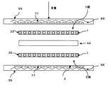
このような貫通孔2内に高分子電解質44を導入するにあたって、図7を用いてその方法を説明する。ヒータ66が内蔵されたホットプレス機55等を用いて、金属製基材1片面側から高分子電解質44を熱圧着する。高分子電解質44は例えばNafion(Dupont製)等でよい。熱圧着温度は高分子電解質44のTg(ガラス転移温度)の5〜50℃前後高温側がよい。Nafionの場合、Tgが130℃前後とされているため、熱圧着温度は100℃〜180℃であることが望まれる。Nafionの場合、熱圧着圧力は1〜7MPaの範囲にあることがよい。
A method for introducing the
ここでホットプレス機55の金属製基材1側には、空気抜き溝77が加工されている。このため熱圧着時に金属製基材1内の貫通孔2から空気が抜けるため、金属製基材と高分子電解質の間に隙間なく高分子電解質44が導入される。さらにこの工程を真空中、もしくは減圧中でおこなってもよい。より空気が金属製基材1の貫通孔2内に空気が残らないため、隙間なく高分子電解質44が導入できる。
Here, an
隙間ができると高分子電解質44が厚み方向で途切れてしまい、良好なプロトン導電性を示さないが、このようにして熱圧着された場合は、高分子電解質44が途中で途切れることなく良好なプロトン導電性を示し、性能低下がほとんどない。また隙間によって起こり得るアノードからカソード、もしくはカソードからアノードのガスリークを防ぐことが出来る。さらに補強材と高分子電解質の界面への水の進入を防ぐことができるため、補強材と高分子電解質の剥離を防ぎ耐久性を向上させる事ができる。
When the gap is formed, the
尚、熱圧着する高分子電解質44は膜状であっても、粒子状であってもよい。均一に高分子電解質44を導入するためには膜状の方が望ましい。このようにして図8のような補強電解質膜88を得る。
The
しかしながら、高分子電解質44と反対側(B面)の金属製基材1表面には高分子電解質44が導入されないことがある。また金属製基材1の外周部(C面)にも高分子電解質44が導入されないことがある。このため、この表面及び外周部に別途、高分子電解質溶液9Aもしくは高分子電解質溶融体9Bを塗布するとよい。こうすることによって、高分子電解質44が途切れることなく良好なプロトン伝導性を示し、性能低下を防ぐことができる。また金属製基材1を確実にポリマでコーティングすることにより、外部へのガスリークを低減させるとともに、電子絶縁性を向上させ、電流のリークをなくし性能低下を防ぐことができる。さらに金属製基材1からのイオン等溶出を低下させることによって触媒被毒を防ぐことができる。
However, the
一般的に高分子電解質44は高IECの方がTgが低いため、高分子電解質44は高IECの方が熱圧着温度を低くすることができ、作業が容易になる。また高分子電解質44の熱劣化を防ぐという効果もある。ここで、図9に示すとおり、高IEC高分子電解質10を熱圧着にてA面から導入した場合を説明する。この場合、高IEC 高分子電解質10はより高いプロトン導電性を示すため、高性能の補強電解質膜111が得られる。しかしながら高IEC高分子電解質10は上記のとおりTgが低いため容易に軟化し、変形、クラック等が発生したり、高温高湿下おいて電解質が流出するという問題が起こる可能性がある。このため、B面、C面に低IEC高分子電解質溶液12Aもしくは高分子電解質溶融体12Bを塗布すると良い。さらにA面にも低IEC高分子電解質溶液12Aもしくは高分子電解質溶融体12B塗布しても良い。こうすることによって、上記変形や、クラック、電解質の流出をふせぐことができる。
In general, the
このような補強電解質膜88を用いたMEA13(Membrane& electroassembly)の作成を図10を用いて説明する。Pt等の触媒を担持したカーボン粒子と高分子電解質、例えばNafion溶液とのスラリーをカーボンペーパ等のガス拡散シートに塗布し触媒層140とガス拡散層150を形成し、これと補強電解質膜88とを熱をかけ接合しMEA13とする。
The creation of MEA 13 (Membrane & electroassembly) using such a reinforced
次に図11を用いて本発明の第5実施形態を説明する。高分子電解質44の両面から金属製基材1をホットプレス機55を用いて熱圧着させる。このとき、ホットプレス機55の表面、金属製基材1のD面側端面、E面側端面に空気抜き溝77を設け、熱圧着時に金属製基材1の貫通孔2から空気が抜けるようにする。熱圧着条件、材料等は第4実施形態と同様でよい。このようにして補強電解質膜16を得る。また図12のように熱圧着後に金属製基材1の両面(E、D面)及び周囲(F面)に高分子電解質溶液9Aもしくは高分子電解質溶融体9Bを塗布してもよい。これら電解質のIECは第一実施例と同様に熱圧着する高分子電解質は高IEC、塗布する高分子電解質は低IECでも良い。
Next, a fifth embodiment of the present invention will be described with reference to FIG. The
このように高分子電解質の両側共に金属製基材を設けることによって、第4実施形態よりもより高強度を達成できるため、より耐久性を向上させることができる。
この補強電解質16を用いたMEAの作製も第一実施形態と同様である。
By providing a metal base on both sides of the polymer electrolyte in this way, higher strength can be achieved than in the fourth embodiment, and thus durability can be further improved.
The production of MEA using this reinforced
本発明は、前記補強電解質膜、および補強電解質膜積層体を用いた膜電極接合体(本明細書において補強電解質膜複合体とも称する)であり、また当該膜電極接合体を用いたことを特徴とする燃料電池である。 The present invention is a membrane electrode assembly (also referred to as a reinforced electrolyte membrane composite in the present specification) using the reinforced electrolyte membrane and the reinforced electrolyte membrane laminate, and is characterized by using the membrane electrode assembly. This is a fuel cell.
本発明のMEAの製造方法の好ましい態様を説明する。なお、以下の態様は、本発明の好ましい態様を示したものであり、本発明のMEAの製造方法が下記方法に限定されるものではない。 The preferable aspect of the manufacturing method of MEA of this invention is demonstrated. In addition, the following aspects show the preferable aspect of this invention, and the manufacturing method of MEA of this invention is not limited to the following method.
まず、本発明の触媒インクを転写用台紙上に塗布・乾燥して、電極触媒層を形成する。 First, the catalyst ink of the present invention is applied and dried on a transfer mount to form an electrode catalyst layer.
この際、転写用台紙としては、PTFE(ポリテトラフルオロエチレン)シート、PET(ポリエチレンテレフタレート)シート、ポリエステルシートなどの公知のシートが使用できる。なお、転写用台紙は、使用する触媒インクの種類に応じて適宜選択される。また、上記工程において、電極触媒層の厚みは、水素の酸化反応(アノード側)及び酸素の還元反応(カソード側)の触媒作用が十分発揮できる厚みであれば特に制限されず、従来と同様の厚みが使用できる。具体的には、電極触媒層の厚みは、5〜30μm、より好ましくは10〜20μmである。 In this case, as the transfer mount, a known sheet such as a PTFE (polytetrafluoroethylene) sheet, a PET (polyethylene terephthalate) sheet, or a polyester sheet can be used. The transfer mount is appropriately selected according to the type of catalyst ink to be used. In the above process, the thickness of the electrode catalyst layer is not particularly limited as long as it can sufficiently exhibit the catalytic action of the hydrogen oxidation reaction (anode side) and the oxygen reduction reaction (cathode side). Thickness can be used. Specifically, the thickness of the electrode catalyst layer is 5 to 30 μm, more preferably 10 to 20 μm.
また、転写用台紙上への触媒インクの塗布方法は、特に制限されず、スクリーン印刷法、沈積法、あるいはスプレー法などの公知の方法が同様にして適用できる。また、塗布された電極触媒層の乾燥条件もまた、電極触媒層から極性溶剤を完全に除去できる条件であれば特に制限されない。具体的には、触媒インクの塗布層(電極触媒層)の塗布層を真空乾燥機内にて、室温〜100℃、より好ましくは50〜80℃で、30〜60分間、乾燥する。この際、触媒層の厚みが十分でない場合には、所望の厚みになるまで、上記塗布・乾燥工程を繰り返す。次に、このようにして作製された触媒層で補強電解質膜(積層体)を挟持した後、当該積層についてホットプレスを行なう。この際、ホットプレス条件は、電極触媒層及び補強電解質膜(積層体)が十分密接に接合できる条件であれば特に制限されないが、100〜200℃、より好ましくは120〜180℃で、電極面に対して1〜7MPaのプレス圧力で行なうのが好ましい。これにより補強電解質膜(積層体)および電極触媒層との接合性を高めることができる。 The method for applying the catalyst ink onto the transfer mount is not particularly limited, and a known method such as a screen printing method, a deposition method, or a spray method can be similarly applied. Also, the drying conditions of the applied electrode catalyst layer are not particularly limited as long as the polar solvent can be completely removed from the electrode catalyst layer. Specifically, the coating layer of the catalyst ink coating layer (electrode catalyst layer) is dried in a vacuum dryer at room temperature to 100 ° C., more preferably 50 to 80 ° C., for 30 to 60 minutes. At this time, if the thickness of the catalyst layer is not sufficient, the coating and drying process is repeated until a desired thickness is obtained. Next, after sandwiching the reinforcing electrolyte membrane (laminated body) with the catalyst layer thus produced, hot pressing is performed on the laminated layer. At this time, the hot press conditions are not particularly limited as long as the electrode catalyst layer and the reinforced electrolyte membrane (laminated body) can be joined sufficiently closely, but are 100 to 200 ° C., more preferably 120 to 180 ° C. The pressure is preferably 1 to 7 MPa. Thereby, bondability with a reinforced electrolyte membrane (laminated body) and an electrode catalyst layer can be improved.
ホットプレスを行なった後、転写用台紙を剥がすことにより、電極触媒層および補強電解質膜(積層体)を含む補強電解質膜複合体を得ることができる。なお、本発明による膜電極接合体は、下記に詳述されるように、一般的にガス拡散層をさらに有しており、この際、ガス拡散層は、上記方法において、転写用台紙を剥がし、得られた接合体をさらにガス拡散層で挟持することによって、電極触媒層および補強電解質膜(積層体)との接合後にさらに各電極触媒層に接合することが好ましい。または、電極触媒層を予めガス拡散層表面上に形成して電極触媒層−ガス拡散層接合体を製造した後、上記したのと同様にして、この電極触媒層−ガス拡散層接合体で補強電解質膜(積層体)をホットプレスにより挟持・接合することもまた好ましい。 After performing the hot pressing, the reinforced electrolyte membrane composite including the electrode catalyst layer and the reinforced electrolyte membrane (laminated body) can be obtained by peeling off the transfer mount. The membrane electrode assembly according to the present invention generally further includes a gas diffusion layer as described in detail below. At this time, the gas diffusion layer peels off the transfer mount in the above method. It is preferable that the obtained joined body is further sandwiched between gas diffusion layers to further join each electrode catalyst layer after joining the electrode catalyst layer and the reinforcing electrolyte membrane (laminated body). Alternatively, an electrode catalyst layer is formed on the surface of the gas diffusion layer in advance to produce an electrode catalyst layer-gas diffusion layer assembly, and then reinforced with the electrode catalyst layer-gas diffusion layer assembly in the same manner as described above. It is also preferable to sandwich and bond the electrolyte membrane (laminated body) by hot pressing.
尚、前記のホットプレス方法以外に、ガス拡散層上に逐次塗布により電極触媒層−補強電解質膜(積層体)−電極触媒層−ガス拡散層を積層する方法を用いても良い。 In addition to the hot pressing method described above, a method of laminating an electrode catalyst layer, a reinforced electrolyte membrane (laminated body), an electrode catalyst layer, and a gas diffusion layer by sequential coating on the gas diffusion layer may be used.
本発明に係る電極触媒層に用いられる触媒成分として、カソード触媒層では、酸素の還元反応に触媒作用を有するものであれば特に制限はなく公知の触媒が同様にして使用できる。また、アノード触媒層に用いられる触媒成分もまた、水素の酸化反応に触媒作用を有するものであれば特に制限はなく公知の触媒が同様にして使用できる。具体的には、白金、ルテニウム、イリジウム、ロジウム、パラジウム、オスミウム、タングステン、鉛、鉄、クロム、コバルト、ニッケル、マンガン、バナジウム、モリブデン、ガリウム、アルミニウム等の金属、及びそれらの合金等などから選択される。これらのうち、触媒活性、一酸化炭素等に対する耐被毒性、耐熱性などを向上させるために、少なくとも白金を含むものが好ましく用いられる。 As the catalyst component used in the electrode catalyst layer according to the present invention, the cathode catalyst layer is not particularly limited as long as it has a catalytic action for the oxygen reduction reaction, and a known catalyst can be used in the same manner. Further, the catalyst component used in the anode catalyst layer is not particularly limited as long as it has a catalytic action for the oxidation reaction of hydrogen, and a known catalyst can be used in the same manner. Specifically, it is selected from platinum, ruthenium, iridium, rhodium, palladium, osmium, tungsten, lead, iron, chromium, cobalt, nickel, manganese, vanadium, molybdenum, gallium, aluminum and the like, and alloys thereof. Is done. Among these, those containing at least platinum are preferably used in order to improve catalyst activity, poisoning resistance to carbon monoxide and the like, heat resistance, and the like.
前記合金の組成は、合金化する金属の種類にもよるが、白金が30〜90原子%、合金化する金属が10〜70原子%とするのがよい。カソード触媒をして合金を使用する場合の合金の組成は、合金化する金属の種類などによって異なり、当業者が適宜選択できるが、白金が30〜90原子%、合金化する他の金属が10〜70原子%とすることが好ましい。なお、合金とは、一般に金属元素に1種以上の金属元素または非金属元素を加えたものであって、金属的性質をもっているものの総称である。 The composition of the alloy is preferably 30 to 90 atomic% for platinum and 10 to 70 atomic% for the metal to be alloyed, depending on the type of metal to be alloyed. The composition of the alloy when the alloy is used as a cathode catalyst varies depending on the type of metal to be alloyed and can be appropriately selected by those skilled in the art, but platinum is 30 to 90 atomic%, and other metals to be alloyed are 10 It is preferable to set it to -70 atomic%. In general, an alloy is a generic term for an element obtained by adding one or more metal elements or non-metal elements to a metal element and having metallic properties.
合金の組織には、成分元素が別個の結晶となるいわば混合物である共晶合金、成分元素が完全に溶け合い固溶体となっているもの、成分元素が金属間化合物または金属と非金属との化合物を形成しているものなどがあり、本願ではいずれであってもよい。この際、カソード触媒層に用いられる触媒成分及びアノード触媒層に用いられる触媒成分は、上記の中から適宜選択できる。以下の説明では、特記しない限り、カソード触媒層及びアノード触媒層用の触媒成分についての説明は、両者について同様の定義であり、一括して、「触媒成分」と称する。しかしながら、カソード触媒層及びアノード触媒層用の触媒成分は同一である必要はなく、上記したような所望の作用を奏するように、適宜選択される。 The alloy structure consists of a eutectic alloy, which is a mixture of component elements that form separate crystals, a component element that completely dissolves into a solid solution, and a component element that is an intermetallic compound or a compound of a metal and a nonmetal. There is what is formed, and any may be used in the present application. At this time, the catalyst component used for the cathode catalyst layer and the catalyst component used for the anode catalyst layer can be appropriately selected from the above. In the following description, unless otherwise specified, the description of the catalyst component for the cathode catalyst layer and the anode catalyst layer has the same definition for both, and is collectively referred to as “catalyst component”. However, the catalyst components for the cathode catalyst layer and the anode catalyst layer do not need to be the same, and are appropriately selected so as to exhibit the desired action as described above.
触媒成分の形状や大きさは、特に制限されず公知の触媒成分と同様の形状及び大きさが使用できるが、触媒成分は、粒状であることが好ましい。この際、触媒スラリーに用いられる触媒成分の平均粒子径は、小さいほど電気化学反応が進行する有効電極面積が増加するため酸素還元活性も高くなり好ましいが、実際には平均粒子径が小さすぎると却って酸素還元活性が低下する現象が見られる。従って、触媒スラリーに含まれる触媒成分の平均粒子径は、1〜30nm、より好ましくは1.5〜20nm、さらにより好ましくは2〜10nm、特に好ましくは2〜5nmの粒状であることが好ましい。担持の容易さという観点から1nm以上であることが好ましく、触媒利用率の観点から30nm以下であることが好ましい。なお、本発明における「触媒成分の平均粒径」は、X線回折における触媒成分の回折ピークの半値幅より求められる結晶子径あるいは透過型電子顕微鏡像より調べられる触媒成分の粒子径の平均値により測定することができる。 The shape and size of the catalyst component are not particularly limited, and the same shape and size as known catalyst components can be used, but the catalyst component is preferably granular. At this time, the smaller the average particle size of the catalyst component used in the catalyst slurry, the higher the effective electrode area where the electrochemical reaction proceeds, and thus the higher the oxygen reduction activity, but in reality the average particle size is too small. On the other hand, a phenomenon in which the oxygen reduction activity decreases is observed. Therefore, the average particle diameter of the catalyst component contained in the catalyst slurry is preferably 1 to 30 nm, more preferably 1.5 to 20 nm, even more preferably 2 to 10 nm, and particularly preferably 2 to 5 nm. It is preferably 1 nm or more from the viewpoint of easy loading, and preferably 30 nm or less from the viewpoint of catalyst utilization. The “average particle diameter of the catalyst component” in the present invention is the average value of the particle diameter of the catalyst component determined from the crystallite diameter or transmission electron microscope image obtained from the half width of the diffraction peak of the catalyst component in X-ray diffraction. Can be measured.
本発明に係る触媒層に用いられる電極触媒は、導電性材料に触媒成分が担持されてなるものである。 The electrode catalyst used in the catalyst layer according to the present invention is formed by supporting a catalyst component on a conductive material.
前記導電性材料としては、触媒成分を所望の分散状態で担持させるための比表面積を有し、集電体として十分な電子導電性を有しているものであればよく、主成分がカーボンであるのが好ましい。具体的には、カーボンブラック、活性炭、コークス、天然黒鉛、人造黒鉛などからなるカーボン粒子が挙げられる。なお、本発明において「主成分がカーボンである」とは、主成分として炭素原子を含むことをいい、炭素原子のみからなる、実質的に炭素原子からなる、の双方を含む概念である。場合によっては、燃料電池の特性を向上させるために、炭素原子以外の元素が含まれていてもよい。なお、実質的に炭素原子からなるとは、2〜3質量%程度以下の不純物の混入が許容されることを意味する。 The conductive material may be any material that has a specific surface area for supporting the catalyst component in a desired dispersed state and has sufficient electronic conductivity as a current collector. The main component is carbon. Preferably there is. Specific examples include carbon particles made of carbon black, activated carbon, coke, natural graphite, artificial graphite and the like. In the present invention, “the main component is carbon” refers to containing a carbon atom as a main component, and is a concept including both a carbon atom only and a substantially carbon atom. In some cases, elements other than carbon atoms may be included in order to improve the characteristics of the fuel cell. In addition, being substantially composed of carbon atoms means that mixing of impurities of about 2 to 3% by mass or less is allowed.
前記導電性材料のBET比表面積は、触媒成分を高分散担持させるのに十分な比表面積であればよいが、好ましくは20〜1600m2/g、より好ましくは80〜1200m2/gとするのがよい。前記比表面積が、20m2/g未満であると前記導電性材料への触媒成分および高分子電解質の分散性が低下して十分な発電性能が得られない恐れがあり、1600m2/gを超えると触媒成分および高分子電解質の有効利用率が却って低下する恐れがある。 The BET specific surface area of the conductive material may be a specific surface area sufficient to support the catalyst component in a highly dispersed state, but is preferably 20 to 1600 m 2 / g, more preferably 80 to 1200 m 2 / g. Is good. If the specific surface area is less than 20 m 2 / g, the dispersibility of the catalyst component and the polymer electrolyte in the conductive material may be reduced, and sufficient power generation performance may not be obtained, and the specific surface area exceeds 1600 m 2 / g. In addition, the effective utilization rate of the catalyst component and the polymer electrolyte may decrease instead.
また、前記導電性材料の大きさは、特に限定されないが、担持の容易さ、触媒利用率、電極触媒層の厚みを適切な範囲で制御するなどの観点からは、平均粒子径が5〜200nm、好ましくは10〜100nm程度とするのがよい。 In addition, the size of the conductive material is not particularly limited, but from the viewpoint of controlling the ease of loading, the catalyst utilization, and the thickness of the electrode catalyst layer within an appropriate range, the average particle size is 5 to 200 nm. The thickness is preferably about 10 to 100 nm.
前記導電性材料に触媒成分が担持された電極触媒において、触媒成分の担持量は、電極触媒の全量に対して、好ましくは10〜80質量%、より好ましくは30〜70質量%とするのがよい。前記担持量が、80質量%を超えると、触媒成分の導電性材料上での分散度が下がり、担持量が増加するわりに発電性能の向上が小さく経済上での利点が低下する恐れがある。また、前記担持量が、10質量%未満であると、単位質量あたりの触媒活性が低下して所望の発電性能を得るために多量の電極触媒が必要となり好ましくない。なお、触媒成分の担持量は、誘導結合プラズマ発光分光法(ICP)によって調べることができる。 In the electrode catalyst in which the catalyst component is supported on the conductive material, the supported amount of the catalyst component is preferably 10 to 80% by mass, more preferably 30 to 70% by mass with respect to the total amount of the electrode catalyst. Good. When the loading amount exceeds 80% by mass, the degree of dispersion of the catalyst component on the conductive material is lowered, and although the loading amount is increased, the improvement in power generation performance is small and the economic advantage may be lowered. On the other hand, if the loading amount is less than 10% by mass, the catalytic activity per unit mass is lowered, and a large amount of electrode catalyst is required to obtain the desired power generation performance, which is not preferable. The amount of the catalyst component supported can be examined by inductively coupled plasma emission spectroscopy (ICP).
本発明に係る電極触媒層におけるイオン導電性高分子は、特に限定されず公知のものを用いることができるが、高分子電解質に用いられたものと同様の材料が挙げられ、少なくとも高いプロトン伝導性を有する材料であればよい。本発明のカソード触媒層/アノード触媒層(以下、単に「触媒層」とも称する)には、電極触媒の他に、高分子電解質が含まれる。この際使用できる高分子電解質は、高分子骨格の全部又は一部にフッ素原子を含むフッ素系電解質と、高分子骨格にフッ素原子を含まない炭化水素系電解質とに大別される。 The ion conductive polymer in the electrode catalyst layer according to the present invention is not particularly limited and known ones can be used, but the same materials as those used for the polymer electrolyte can be used, and at least high proton conductivity can be used. Any material that has The cathode catalyst layer / anode catalyst layer (hereinafter also simply referred to as “catalyst layer”) of the present invention contains a polymer electrolyte in addition to the electrode catalyst. The polymer electrolyte that can be used in this case is roughly classified into a fluorine-based electrolyte containing fluorine atoms in the whole or a part of the polymer skeleton and a hydrocarbon-based electrolyte not containing fluorine atoms in the polymer skeleton.
前記フッ素系電解質として、具体的には、ナフィオン(登録商標、デュポン社製)、アシプレックス(登録商標、旭化成株式会社製)、フレミオン(登録商標、旭硝子株式会社製)等のパーフルオロカーボンスルホン酸系高分子、ポリトリフルオロスチレンスルフォン酸系高分子、パーフルオロカーボンホスホン酸系高分子、トリフルオロスチレンスルホン酸系高分子、エチレンテトラフルオロエチレン−g−スチレンスルホン酸系高分子、エチレン−テトラフルオロエチレン共重合体、ポリビニリデンフルオリド−パーフルオロカーボンスルホン酸系高分子などが好適な一例として挙げられる。 Specific examples of the fluorine electrolyte include perfluorocarbon sulfonic acids such as Nafion (registered trademark, manufactured by DuPont), Aciplex (registered trademark, manufactured by Asahi Kasei Co., Ltd.), and Flemion (registered trademark, manufactured by Asahi Glass Co., Ltd.). Polymer, polytrifluorostyrene sulfonic acid polymer, perfluorocarbon phosphonic acid polymer, trifluorostyrene sulfonic acid polymer, ethylene tetrafluoroethylene-g-styrene sulfonic acid polymer, ethylene-tetrafluoroethylene Preferred examples include polymers and polyvinylidene fluoride-perfluorocarbon sulfonic acid polymers.
前記炭化水素系電解質として、具体的には、ポリスルホンスルホン酸、ポリアリールエーテルケトンスルホン酸、ポリベンズイミダゾールアルキルスルホン酸、ポリベンズイミダゾールアルキルホスホン酸、ポリスチレンスルホン酸、ポリエーテルエーテルケトンスルホン酸、ポリフェニルスルホン酸等が好適な一例として挙げられる。 Specific examples of the hydrocarbon electrolyte include polysulfone sulfonic acid, polyaryl ether ketone sulfonic acid, polybenzimidazole alkyl sulfonic acid, polybenzimidazole alkyl phosphonic acid, polystyrene sulfonic acid, polyether ether ketone sulfonic acid, polyphenyl. A suitable example is sulfonic acid.
高分子電解質は、耐熱性、化学的安定性などに優れることから、フッ素原子を含むのが好ましく、なかでも、ナフィオン(登録商標、デュポン社製)、アシプレックス(登録商標、旭化成株式会社製)、フレミオン(登録商標、旭硝子株式会社製)などのフッ素系電解質が好ましく挙げられる。 The polymer electrolyte preferably contains a fluorine atom because of its excellent heat resistance and chemical stability. Among them, Nafion (registered trademark, manufactured by DuPont), Aciplex (registered trademark, manufactured by Asahi Kasei Co., Ltd.) Fluorine electrolytes such as Flemion (registered trademark, manufactured by Asahi Glass Co., Ltd.) are preferred.
また、導電性材料への触媒成分の担持は公知の方法で行うことができる。例えば、含浸法、液相還元担持法、蒸発乾固法、コロイド吸着法、噴霧熱分解法、逆ミセル(マイクロエマルジョン法)などの公知の方法が使用できる。または、電極触媒は、市販品を用いてもよい。 The catalyst component can be supported on the conductive material by a known method. For example, known methods such as impregnation method, liquid phase reduction support method, evaporation to dryness method, colloid adsorption method, spray pyrolysis method, reverse micelle (microemulsion method) can be used. Alternatively, a commercially available electrode catalyst may be used.
尚、高分子電解質膜と電極層とで用いる高分子電解質は、異なってもよいが、膜と電極の接触抵抗などを考慮すると同じものを用いるのが好ましい。 The polymer electrolyte used in the polymer electrolyte membrane and the electrode layer may be different, but it is preferable to use the same polymer electrolyte considering the contact resistance between the membrane and the electrode.
前記高分子電解質は、接着の役割をする高分子として電極触媒を被覆しているのが好ましい。これにより、電極の構造を安定に維持できるとともに、電極反応が進行する三相界面を十分に確保して、高い触媒活性を得ることができる。電極中に含まれる前記固体高分子電解質の含有量は、特に限定されないが、触媒成分の全量に対して25〜35質量%とするのがよい。 The polymer electrolyte is preferably coated with an electrode catalyst as a polymer that functions as an adhesive. Thereby, while being able to maintain the structure of an electrode stably, the sufficient three-phase interface where an electrode reaction advances can be ensured, and high catalyst activity can be obtained. Although content of the said solid polymer electrolyte contained in an electrode is not specifically limited, It is good to set it as 25-35 mass% with respect to the whole quantity of a catalyst component.
本発明に係るガス拡散層(以下GDLと称する)に用いられる材料としては、カーボンペーパー、不織布、炭素製の織物、紙状抄紙体、フェルトなどからなるシート状材料が提案されている。GDLが優れた電子伝導性を有していると、発電反応により生じた電子の効率的な運搬が達成され、燃料電池の性能が向上する。またGDLが優れた撥水性を有していると、生成した水が効率的に排出される。 As a material used for the gas diffusion layer (hereinafter referred to as GDL) according to the present invention, a sheet-like material made of carbon paper, non-woven fabric, carbon woven fabric, paper-like paper body, felt or the like has been proposed. When GDL has excellent electron conductivity, efficient transport of electrons generated by a power generation reaction is achieved, and the performance of the fuel cell is improved. Further, if the GDL has an excellent water repellency, the generated water is efficiently discharged.
高い撥水性を確保するために、GDLを構成する材料を撥水処理する技術も提案されている。例えば、ポリテトラフルオロエチレン(PTFE)などのフッ素系樹脂を含む溶液中にカーボンペーパーなどのGDLを構成する材料を含浸させ、大気中または窒素などの不活性ガス中に乾燥させる。場合によっては、親水化処理がGDLを構成する材料に施されてもよい。 In order to ensure high water repellency, a technique for water repellency treatment of a material constituting the GDL has also been proposed. For example, a solution containing a fluorine-based resin such as polytetrafluoroethylene (PTFE) is impregnated with a material constituting GDL such as carbon paper, and dried in the air or an inert gas such as nitrogen. Depending on the case, the hydrophilization treatment may be performed on the material constituting the GDL.
その他に、カーボンペーパー、不織布、炭素製の織物、紙状抄紙体、フェルトなどからなるシート状GDL上に、カーボン粒子およびバインダーを配置して、両者をガス拡散層として使用してもよく、カーボン粒子およびバインダーからなるフィルム自体をガス拡散層として使用してもよい。この結果、フィルム自体に均一に撥水材料、カーボン粒子が形成されているため、上記の塗布に比較して撥水効率の上昇がみられる。 In addition, carbon particles and a binder may be disposed on a sheet-like GDL made of carbon paper, nonwoven fabric, carbon fabric, paper-like paper body, felt, etc., and both may be used as a gas diffusion layer. You may use the film itself which consists of particle | grains and a binder as a gas diffusion layer. As a result, since the water repellent material and the carbon particles are uniformly formed on the film itself, the water repellent efficiency is increased as compared with the above application.
前記撥水材料としては、ポリテトラフルオロエチレン(PTFE)、ポリフッ化ビニリデン(PVDF)、ポリヘキサフルオロプロピレン、テトラフルオロエチレン−ヘキサフルオロプロピレン共重合体(FEP)などのフッ素系樹脂、ポリプロピレン、ポリエチレンなどが挙げられる。なかでも、撥水性、電極反応時の耐食性などに優れることから、フッ素系樹脂が好ましい。
尚、「バインダー」とは接着の役割を有する物質をいい、本発明に係る実施例では、バインダーの役割および撥水性の役割を兼ね備えたフッ素系樹脂を使用しているが、必ずしもこれに限定されず、バインダーおよび撥水材料を個々独立した物質で混合して使用しても良い。
Examples of the water repellent material include fluorine resins such as polytetrafluoroethylene (PTFE), polyvinylidene fluoride (PVDF), polyhexafluoropropylene, and tetrafluoroethylene-hexafluoropropylene copolymer (FEP), polypropylene, polyethylene, and the like. Is mentioned. Of these, fluororesins are preferred because they are excellent in water repellency and corrosion resistance during electrode reaction.
Incidentally, the “binder” refers to a substance having a role of adhesion, and in the examples according to the present invention, a fluororesin having both a role of a binder and a role of water repellency is used, but it is not necessarily limited thereto. Alternatively, the binder and the water repellent material may be mixed and used as independent substances.
本発明に係るアノード側電極触媒層およびカソード側電極触媒層は、触媒金属、プロトン伝導性高分子、撥水材料を含む。 The anode side electrode catalyst layer and the cathode side electrode catalyst layer according to the present invention include a catalyst metal, a proton conductive polymer, and a water repellent material.
前記電極触媒層の空孔率は、30〜70%が好ましく、より好ましくは40〜60%である。空孔率が30%未満では、ガスの拡散が十分ではなく、高電流域でのセル電圧が低下する。また、空孔率が70%超では、電極触媒層の強度が十分ではなく、転写プロセスにおいて空孔率が低下する。 The porosity of the electrode catalyst layer is preferably 30 to 70%, more preferably 40 to 60%. If the porosity is less than 30%, gas diffusion is not sufficient, and the cell voltage in the high current region decreases. On the other hand, when the porosity exceeds 70%, the strength of the electrode catalyst layer is not sufficient, and the porosity decreases in the transfer process.
本発明では、従来公知の方法と同様の方法によってMEA(膜−電極接合体(膜電極接合体または補強電解質膜複合体とも称する))が製造できる。例えば、調製された触媒スラリーを所望の厚さで転写用台紙上に塗布・乾燥することによって、カソード側及びアノード側の電極触媒層を形成し、さらにこの電極触媒層が内側にくるように高分子電解質膜を上記電極触媒層で挟持してホットプレス等により接合した後、転写用台紙を剥がすことによって、膜電極接合体が得られる。 In the present invention, MEA (membrane-electrode assembly (also referred to as membrane electrode assembly or reinforced electrolyte membrane composite)) can be produced by a method similar to a conventionally known method. For example, by applying and drying the prepared catalyst slurry on a transfer mount with a desired thickness, an electrode catalyst layer on the cathode side and the anode side is formed, and the electrode catalyst layer is placed so that the electrode catalyst layer is on the inside. After the molecular electrolyte membrane is sandwiched between the electrode catalyst layers and bonded by hot pressing or the like, the transfer mount is peeled off to obtain a membrane / electrode assembly.
本発明の触媒スラリーにおいて、電極触媒は、所望の作用、即ち、水素の酸化反応(アノード側)及び酸素の還元反応(カソード側)を触媒する作用を十分発揮できる量であればいずれの量で、使用されてもよい。電極触媒が、触媒スラリー中、0.5〜3質量%、より好ましくは1〜2質量%となるような量で存在することが好ましい。 In the catalyst slurry of the present invention, the electrode catalyst may be used in any amount as long as it can sufficiently exhibit the desired action, that is, the action of catalyzing the hydrogen oxidation reaction (anode side) and the oxygen reduction reaction (cathode side). , May be used. The electrode catalyst is preferably present in the catalyst slurry in an amount of 0.5 to 3% by mass, more preferably 1 to 2% by mass.
本発明の触媒スラリーには、電極触媒、電解質及び溶剤に加えて、ポリテトラフルオロエチレン、ポリヘキサフルオロプロピレン、テトラフルオロエチレン−ヘキサフルオロプロピレン共重合体といった撥水性高分子などが含まれてもよい。これにより、得られる電極触媒層の撥水性を高めることができ、発電時に生成した水などを速やかに排出することができる。撥水性高分子を使用する際の、撥水性高分子の添加量は、本発明の上記効果を妨げない程度の量であれば特に制限されない。 The catalyst slurry of the present invention may contain a water-repellent polymer such as polytetrafluoroethylene, polyhexafluoropropylene, and tetrafluoroethylene-hexafluoropropylene copolymer in addition to the electrode catalyst, the electrolyte, and the solvent. . Thereby, the water repellency of the obtained electrode catalyst layer can be increased, and water generated at the time of power generation can be quickly discharged. The amount of the water-repellent polymer added when the water-repellent polymer is used is not particularly limited as long as it is an amount that does not interfere with the effects of the present invention.
上記撥水性高分子に代えてまたは上記撥水性高分子に加えて、本発明の触媒スラリーは、増粘剤を含んでもよい。増粘剤の使用は、触媒スラリーなどが転写用台紙上にうまく塗布できない場合などに有効である。この際使用できる増粘剤は、特に制限されず、公知の増粘剤が使用できるが、例えば、グリセリン、(EG(エチレングリコール)、PVA(ポリビニルアルコール))などが挙げられる。増粘剤を使用する際の、増粘剤の添加量は、本発明の上記効果を妨げない程度の量であれば特に制限されない。 Instead of the water-repellent polymer or in addition to the water-repellent polymer, the catalyst slurry of the present invention may contain a thickener. The use of a thickener is effective when the catalyst slurry or the like cannot be successfully applied onto the transfer mount. The thickener that can be used in this case is not particularly limited, and a known thickener can be used. Examples thereof include glycerin, (EG (ethylene glycol), PVA (polyvinyl alcohol)), and the like. The amount of the thickener added when the thickener is used is not particularly limited as long as it does not interfere with the above-described effect of the present invention.
本発明の触媒スラリーは、電極触媒、電解質及び溶剤、ならびに必要であれば撥水性高分子および/または増粘剤、が適宜混合されたものであればその調製方法は特に制限されなく、さらに、本発明で使用される触媒スラリーを構成する溶剤としては、特に制限されず、触媒層を形成するのに使用される通常の溶剤が同様にして使用できる。具体的には、水、シクロヘキサノールやエタノールや2−プロパノール等の低級アルコールが使用できる。 The catalyst slurry of the present invention is not particularly limited in its preparation method as long as an electrode catalyst, an electrolyte and a solvent, and if necessary, a water-repellent polymer and / or a thickener are appropriately mixed. The solvent constituting the catalyst slurry used in the present invention is not particularly limited, and ordinary solvents used for forming the catalyst layer can be used in the same manner. Specifically, water, lower alcohols such as cyclohexanol, ethanol and 2-propanol can be used.
本発明で使用される溶剤の量は、電解質を完全に溶解できる量であれば特に制限されない。 The amount of the solvent used in the present invention is not particularly limited as long as it can dissolve the electrolyte completely.
前記燃料電池の種類としては、特に限定されず、上記した説明中では高分子電解質型燃料電池を例に挙げて説明したが、この他にも、アルカリ型燃料電池、リン酸型燃料電池に代表される酸型電解質の燃料電池、ダイレクトメタノール型燃料電池、マイクロ燃料電池などが挙げられる。なかでも小型かつ高密度・高出力化が可能であるから、固体高分子電解質型燃料電池が好ましく挙げられる。また、前記燃料電池は、搭載スペースが限定される車両などの移動体用電源の他、定置用電源などとして有用であるが、特にシステムの起動/停止や出力変動が頻繁に発生する自動車用途で特に好適に使用できる。 The type of the fuel cell is not particularly limited. In the above description, the polymer electrolyte fuel cell has been described as an example, but in addition to this, a representative example is an alkaline fuel cell and a phosphoric acid fuel cell. Examples thereof include an acid electrolyte fuel cell, a direct methanol fuel cell, and a micro fuel cell. Among them, a solid polymer electrolyte fuel cell is preferable because it is small in size and can achieve high density and high output. The fuel cell is useful as a stationary power source in addition to a power source for a moving body such as a vehicle in which a mounting space is limited. However, the fuel cell is particularly useful for an automobile application in which system start / stop and output fluctuation frequently occur. It can be particularly preferably used.
前記高分子電解質型燃料電池は、定置用電源の他、搭載スペースが限定される自動車などの移動体用電源などとして有用である。なかでも、比較的長時間の運転停止後に高い出力電圧が要求されることによるカーボン担体の腐食、および、運転時に高い出力電圧が取り出されることにより高分子電解質の劣化が生じやすい自動車などの移動体用電源として用いられるのが特に好ましい。 The polymer electrolyte fuel cell is useful not only as a stationary power source but also as a power source for a moving body such as an automobile having a limited mounting space. In particular, moving bodies such as automobiles that are susceptible to corrosion of the carbon support due to the high output voltage required after a relatively long shutdown, and deterioration of the polymer electrolyte due to the high output voltage being taken out during operation. It is particularly preferred to be used as a power source.
前記燃料電池の構成としては、特に限定されず、従来公知の技術を適宜利用すればよいが、一般的には膜電極接合体をセパレータで挟持した構造を有する。 The configuration of the fuel cell is not particularly limited, and a conventionally known technique may be appropriately used. Generally, the fuel cell has a structure in which a membrane electrode assembly is sandwiched between separators.
前記セパレータとしては、緻密カーボングラファイト、炭素板等のカーボン製や、ステンレス等の金属製のものなど、従来公知のものであれば制限なく用いることができる。セパレータは、空気と燃料ガスとを分離する機能を有するものであり、それらの流路を確保するための流路溝が形成されてもよい。セパレータの厚さや大きさ、流路溝の形状などについては、特に限定されず、得られる燃料電池の出力特性などを考慮して適宜決定すればよい。 The separator can be used without limitation as long as it is conventionally known, such as those made of carbon such as dense carbon graphite and a carbon plate, and those made of metal such as stainless steel. The separator has a function of separating air and fuel gas, and a channel groove for securing the channel may be formed. The thickness and size of the separator, the shape of the flow channel, and the like are not particularly limited, and may be appropriately determined in consideration of the output characteristics of the obtained fuel cell.
また、各触媒層に供給されるガスが外部にリークするのを防止するために、ガスケット層上の触媒層が形成されていない部位にさらにガスシール部が設けられてもよい。前記ガスシール部を構成する材料としては、フッ素ゴム、シリコンゴム、エチレンプロピレンゴム(EPDM)、ポリイソブチレンゴム等のゴム材料、ポリテトラフルオロエチレン(PTFE)、ポリフッ化ビニリデン(PVDF)、ポリヘキサフルオロプロピレン、テトラフルオロエチレン−ヘキサフルオロプロピレン共重合体(FEP)等のフッ素系の高分子材料、ポリオレフィンやポリエステル等の熱可塑性樹脂などが挙げられる。また、ガスシール部の厚さとしては、2mm〜50μm、望ましくは1mm〜100μm程度とすればよい。 Further, in order to prevent the gas supplied to each catalyst layer from leaking to the outside, a gas seal portion may be further provided at a portion where the catalyst layer is not formed on the gasket layer. Examples of the material constituting the gas seal portion include rubber materials such as fluoro rubber, silicon rubber, ethylene propylene rubber (EPDM), polyisobutylene rubber, polytetrafluoroethylene (PTFE), polyvinylidene fluoride (PVDF), polyhexafluoro. Fluorine polymer materials such as propylene, tetrafluoroethylene-hexafluoropropylene copolymer (FEP), and thermoplastic resins such as polyolefin and polyester. The thickness of the gas seal portion may be 2 mm to 50 μm, preferably about 1 mm to 100 μm.
さらに、燃料電池が所望する電圧等を得られるように、セパレータを介して膜電極接合体を複数積層して直列に繋いだスタックを形成してもよい。燃料電池の形状などは、特に限定されず、所望する電圧などの電池特性が得られるように適宜決定すればよい。 Furthermore, a stack in which a plurality of membrane electrode assemblies are stacked via a separator and connected in series may be formed so that the fuel cell can obtain a desired voltage or the like. The shape of the fuel cell is not particularly limited, and may be determined as appropriate so that desired battery characteristics such as voltage can be obtained.
触媒成分、導電性材料、および高分子電解質を含む触媒スラリーを、転写用シート上に塗布する方法は、スクリーンプリント法、スプレー法、ドクターブレード法など、塗布方法には限定されない。 The method of applying the catalyst slurry containing the catalyst component, the conductive material, and the polymer electrolyte on the transfer sheet is not limited to the application method such as the screen printing method, the spray method, and the doctor blade method.
以下、本発明を実施例に基づいて具体的に説明する。下記実施例は、本発明の好ましい一実施形態を示したに過ぎず、本発明がこれに限定されないことはいうまでもない。 Hereinafter, the present invention will be specifically described based on examples. The following example shows only one preferred embodiment of the present invention, and it goes without saying that the present invention is not limited thereto.
(実施例1)
高分子電解質膜(1)
縦×横70mm×70mm、厚さ30μm、材質はステンレスの金属薄膜に、エッチング処理を行い、六角形型形状(外接半径300μm)、残し幅(リブ幅30μm)の貫通孔を加工し空孔率80%の金属製基材とした。
Example 1
Polymer electrolyte membrane (1)
Vertical x horizontal 70mm x 70mm, thickness 30μm, material is etched with a stainless steel metal thin film, and hexagonal shape (circumscribed radius 300μm), leaving the remaining width (rib width 30μm) through hole, porosity An 80% metal substrate was used.
次いで、この薄膜表面および貫通孔断面にシリカコーティングを被覆させた。この際の、コーティング方法はイオンプレーディング方法を用いて行った。このような貫通孔内に高IEC高分子電解質としてスルホン化ポリアリールエーテルスルホン(IEC 1.9meq/g)を 20%MNP溶液として注入し補強電解質膜を作製した。ここでは基材金属上にこの溶液をキャストした。その後、窒素雰囲気中、0.5℃/minの速さで室温から120℃まで昇温し、120℃で6時間保持することによりNMPを除去し補強電解質膜とした。 Next, a silica coating was applied to the thin film surface and the through-hole cross section. In this case, the coating method was performed using an ion plating method. A sulfonated polyarylethersulfone (IEC 1.9 meq / g) as a high IEC polymer electrolyte was injected as a 20% MNP solution into such a through-hole to produce a reinforced electrolyte membrane. Here, this solution was cast on a base metal. Thereafter, the temperature was raised from room temperature to 120 ° C. at a rate of 0.5 ° C./min in a nitrogen atmosphere, and maintained at 120 ° C. for 6 hours to remove NMP to obtain a reinforced electrolyte membrane.
この上下面に通常IEC高分子電解質スルホン化ポリアリールエーテルスルホン(IECは1.1meq/g)の20%NMP溶液を薄く塗布し、窒素雰囲気中、0.5℃/minの速さで室温から120℃まで昇温し、120℃で6時間保持することによりNMPを除去し、多層補強電解質膜とした。高分子電解質の塗布厚は10μmで行ったため多層補強電解質膜の膜膜厚は50μmであった。 A thin 20% NMP solution of IEC polyelectrolyte sulfonated polyarylether sulfone (IEC is 1.1 meq / g) is applied thinly to the upper and lower surfaces, and from room temperature at a rate of 0.5 ° C./min in a nitrogen atmosphere. The temperature was raised to 120 ° C. and held at 120 ° C. for 6 hours to remove NMP to obtain a multilayer reinforced electrolyte membrane. Since the coating thickness of the polymer electrolyte was 10 μm, the film thickness of the multilayer reinforced electrolyte membrane was 50 μm.
得られた多層補強電解質膜のプロトン伝導度は30℃から80℃の範囲で測定した。加湿は水蒸気発生器にて生成する蒸気を使用した。また、イオン伝導度の計算に必要な膜厚は乾燥状態でマイクロメータを用いて測定した。
こうして得た多層補強電解質のプロトン伝導度は2.0×10⁻³S/cm(60℃)であった。
The proton conductivity of the obtained multilayer reinforced electrolyte membrane was measured in the range of 30 ° C to 80 ° C. For the humidification, steam generated by a steam generator was used. Moreover, the film thickness required for calculation of ionic conductivity was measured using a micrometer in a dry state.
The proton conductivity of the multilayer reinforced electrolyte thus obtained was 2.0 × 10 −3 S / cm (60 ° C.).
電極触媒層(2)
ジョンソンマッセイフューエルセルズ社の触媒層付きガス拡散層(市販品)を用いた。得られた多層補強電解質の両側から触媒層つきGDLで挟み、130℃10Mpaで10分間ホットプレスを実施し、図3のようなMEA(アクティブエリア25cm2)とした。
Electrocatalyst layer (2)
A gas diffusion layer with a catalyst layer (commercially available) manufactured by Johnson Matthey Fuel Cells was used. The multilayer reinforcing electrolyte thus obtained was sandwiched between GDLs with a catalyst layer from both sides and hot pressed at 130 ° C. and 10 Mpa for 10 minutes to obtain an MEA (active area 25 cm 2 ) as shown in FIG.
このMEAをエレクトロケム社製シングルセル(アクティブエリア25cm2)にて発電性能の評価を実施した。セル温度は70℃一定で、水素極と空気極に70℃の水素および70℃の空気を供給した結果、得られた発電性能を100とする。 The power generation performance of this MEA was evaluated in a single cell (active area 25 cm 2 ) manufactured by Electrochem. The cell temperature is constant at 70 ° C., and 70 ° C. hydrogen and 70 ° C. air are supplied to the hydrogen electrode and the air electrode.
同様にこのMEAをエレクトロケム社製シングルセル(型番:EFC25−02SP アクティブエリア25cm2 )を用いて繰り返し湿潤−乾燥の耐久試験を実施した。セル温度は70℃一定とした。水素極と空気極に常圧で一定時間(5分間)の湿潤水素(70℃RH90%)と湿潤空気(70℃RH90%)を流した後、一定時間(5分間)の乾燥水素(70℃RH5%)と乾燥空気(70℃RH5%)を供給するモードを一サイクルとし、多層補強電解質膜が破断するまで繰り返した。多層補強電解質膜の破断は水素リーク電流にて検知した。この結果、所定サイクル数を繰り返したときに多層補強電解質膜の水素リークが増加したことによる水素リーク電流の増加が見られ、多層補強電解質膜が破断し、このサイクル数を100とする。
Similarly, this MEA was repeatedly subjected to a wet-dry durability test using a single cell (model number: EFC25-02SP active area 25 cm 2 ) manufactured by Electrochem. The cell temperature was constant at 70 ° C. After flowing wet hydrogen (70 ° C. RH 90%) and wet air (70 ° C. RH 90%) for a fixed time (5 minutes) at normal pressure into a hydrogen electrode and an air electrode, dry hydrogen (70 ° C.) for a fixed time (5 minutes) was passed. The mode in which
(比較例1)
実施例の比較として、補強基材を使用しない電解質膜をMEA化し発電性能と耐久性能を測定した。電解質膜は通常IEC高分子電解質スルホン化ポリアリールエーテルスルホン(IECは1.1meq/g)の20%NMP溶液をガラス基板上にキャストし、窒素雰囲気中、0.5℃/minの速さで室温から120℃まで昇温し、120℃で6時間保持することによりNMPを除去し電解質膜とした。得られた電解質膜は50μmであった。実施例と同様の方法でMEA化し、実施例と同様のシングルセルを用いて、実施例と同様条件において発電性能と湿潤−乾燥耐久性能を取得した。
得られた発電性能は実施例の100と比較すると115であった。
得られた湿潤−乾燥耐久性は実施例のサイクル数を100とした場合に比較して40であった。
(Comparative Example 1)
As a comparison of the examples, an electrolyte membrane that does not use a reinforcing base material was converted to MEA, and power generation performance and durability performance were measured. For the electrolyte membrane, a 20% NMP solution of an IEC polyelectrolyte sulfonated polyarylethersulfone (IEC is 1.1 meq / g) is usually cast on a glass substrate at a rate of 0.5 ° C./min in a nitrogen atmosphere. NMP was removed by raising the temperature from room temperature to 120 ° C. and holding at 120 ° C. for 6 hours to obtain an electrolyte membrane. The obtained electrolyte membrane was 50 μm. Using the same method as in the example, MEA was performed, and using the same single cell as in the example, power generation performance and wet-dry durability performance were obtained under the same conditions as in the example.
The obtained power generation performance was 115 as compared with 100 of the example.
The obtained wet-dry durability was 40 compared to the case where the cycle number of the example was 100.
(比較例2)
実施例の比較として、補強基材を使用しない電解質膜をMEA化し発電性能と耐久性能を測定した。電解質膜は高IEC高分子電解質スルホン化ポリアリールエーテルスルホン(IECは1.9meq/g)の20%NMP溶液をガラス基板上にキャストし、窒素雰囲気中、0.5℃/minの速さで室温から120℃まで昇温し、120℃で6時間保持することによりNMPを除去し電解質膜とした。得られた電解質膜は50μmであった。実施例1、比較例2と同様の方法でMEA化し、実施例、比較例2と同様のシングルセルを用いて、実施例、比較例2と同様条件において発電性能と湿潤−乾燥耐久性能を取得した。
得られた発電性能は実施例の100と比較すると130であった。
得られた湿潤−乾燥耐久性は実施例の100と比較すると15であった。
(Comparative Example 2)
As a comparison of the examples, an electrolyte membrane that does not use a reinforcing base material was converted to MEA, and power generation performance and durability performance were measured. As the electrolyte membrane, a 20% NMP solution of high IEC polyelectrolyte sulfonated polyarylethersulfone (IEC is 1.9 meq / g) was cast on a glass substrate, and the nitrogen membrane was at a rate of 0.5 ° C / min NMP was removed by raising the temperature from room temperature to 120 ° C. and holding at 120 ° C. for 6 hours to obtain an electrolyte membrane. The obtained electrolyte membrane was 50 μm. Using the same method as in Example 1 and Comparative Example 2, MEA was performed, and using the same single cell as in Example and Comparative Example 2, power generation performance and wet-dry durability performance were obtained under the same conditions as in Example and Comparative Example 2. did.
The power generation performance obtained was 130 compared with 100 in the example.
The resulting wet-dry durability was 15 compared to 100 in the example.
上述したように、本発明の補強基材を用いた補強電解質膜、特に多層補強電解質膜は膨潤が抑制されるため、湿潤−乾燥耐久性が大きく向上する。補強基材で膨潤抑制しつつ、面圧による水分の押し出しを抑制したことで、膨潤抑制による性能低下を抑えることができた。 As described above, since the swelling of the reinforced electrolyte membrane using the reinforced substrate of the present invention, particularly the multilayer reinforced electrolyte membrane, is suppressed, the wet-dry durability is greatly improved. By suppressing the extrusion of moisture due to the surface pressure while suppressing the swelling with the reinforcing base material, it was possible to suppress the performance degradation due to the suppression of the swelling.
また多層化(表面に通常IEC電解質を塗布)としたことで外部環境が乾燥状態になっても、補強電解質膜内部の水が乾きにくく膨潤収縮量が低減されたこと、内部に高IEC電解質を使用したことで保水力とプロトン伝導抵抗の低下を抑えたことによって、性能低下を最小限に抑えつつ、大幅な耐久性の向上がもたらされたと考えられる。 Moreover, even if the external environment is in a dry state due to multilayering (usually IEC electrolyte applied to the surface), the water inside the reinforced electrolyte membrane is hard to dry and the amount of swelling shrinkage is reduced, and a high IEC electrolyte is added inside. By using it, it was considered that the decrease in water retention and proton conduction resistance was suppressed, and the durability was greatly improved while minimizing the decrease in performance.
1 金属製基材
2 貫通孔
3 コーティング
4 高分子電解質
5 補強電解質膜
6 触媒層
7 ガス拡散層
8 MEA(補強電解質膜複合体)
10 高IEC高分子電解質
11 通常IEC高分子電解質
13 MEA(補強電解質膜複合体)
12 補強電解質膜積層体
14 通常IEC補強電解質膜
15 高IEC補強電解質膜
16 補強電解質膜積層体
33 コーティング
44 高分子電解質
55 ホットプレス機
66 ヒータ
77 空気抜き溝
88 補強電解質膜
9A 高分子電解質溶液
9B 高分子電解質溶融体
111 補強電解質膜
12A 低IEC高分子電解質溶液
12B 低IEC高分子電解質溶融体
140 触媒層
150 ガス拡散層
DESCRIPTION OF
10 High
12 Reinforced
Claims (21)
を有する補強電解質膜の製造方法。 Thermocompression bonding the polymer electrolyte membrane (a) from one side of a metal substrate having a through-hole,
The manufacturing method of the reinforced electrolyte membrane which has this.
を有する補強電解質膜の製造方法。 Thermocompression bonding a metal substrate having a through hole from both sides of the polymer electrolyte membrane (a),
The manufacturing method of the reinforced electrolyte membrane which has this.
Priority Applications (1)
| Application Number | Priority Date | Filing Date | Title |
|---|---|---|---|
| JP2006075455A JP2007250468A (en) | 2006-03-17 | 2006-03-17 | Electrolyte film |
Applications Claiming Priority (1)
| Application Number | Priority Date | Filing Date | Title |
|---|---|---|---|
| JP2006075455A JP2007250468A (en) | 2006-03-17 | 2006-03-17 | Electrolyte film |
Publications (1)
| Publication Number | Publication Date |
|---|---|
| JP2007250468A true JP2007250468A (en) | 2007-09-27 |
Family
ID=38594515
Family Applications (1)
| Application Number | Title | Priority Date | Filing Date |
|---|---|---|---|
| JP2006075455A Pending JP2007250468A (en) | 2006-03-17 | 2006-03-17 | Electrolyte film |
Country Status (1)
| Country | Link |
|---|---|
| JP (1) | JP2007250468A (en) |
Cited By (5)
| Publication number | Priority date | Publication date | Assignee | Title |
|---|---|---|---|---|
| JP2009170382A (en) * | 2008-01-21 | 2009-07-30 | Fuji Electric Holdings Co Ltd | Manufacturing method for membrane-electrode assembly of fuel cell |
| JP2010123388A (en) * | 2008-11-19 | 2010-06-03 | Nissan Motor Co Ltd | Electrolyte membrane, and membrane electrode assembly as well as fuel cell using the same |
| JP2012079615A (en) * | 2010-10-05 | 2012-04-19 | Toyota Motor Corp | Fuel cell |
| JP2013520779A (en) * | 2010-02-26 | 2013-06-06 | ジョンソン、マッセイ、フュエル、セルズ、リミテッド | Membrane |
| WO2023195623A1 (en) * | 2022-04-04 | 2023-10-12 | 코오롱인더스트리 주식회사 | Polymer electrolyte membrane, method for manufacturing same, and electrochemical device comprising same |
-
2006
- 2006-03-17 JP JP2006075455A patent/JP2007250468A/en active Pending
Cited By (6)
| Publication number | Priority date | Publication date | Assignee | Title |
|---|---|---|---|---|
| JP2009170382A (en) * | 2008-01-21 | 2009-07-30 | Fuji Electric Holdings Co Ltd | Manufacturing method for membrane-electrode assembly of fuel cell |
| JP2010123388A (en) * | 2008-11-19 | 2010-06-03 | Nissan Motor Co Ltd | Electrolyte membrane, and membrane electrode assembly as well as fuel cell using the same |
| JP2013520779A (en) * | 2010-02-26 | 2013-06-06 | ジョンソン、マッセイ、フュエル、セルズ、リミテッド | Membrane |
| JP2017020107A (en) * | 2010-02-26 | 2017-01-26 | ジョンソン、マッセイ、フュエル、セルズ、リミテッドJohnson Matthey Fuel Cells Limited | Membrane |
| JP2012079615A (en) * | 2010-10-05 | 2012-04-19 | Toyota Motor Corp | Fuel cell |
| WO2023195623A1 (en) * | 2022-04-04 | 2023-10-12 | 코오롱인더스트리 주식회사 | Polymer electrolyte membrane, method for manufacturing same, and electrochemical device comprising same |
Similar Documents
| Publication | Publication Date | Title |
|---|---|---|
| US8026018B2 (en) | Electrolyte membrane-electrode assembly and production method thereof | |
| JP5326189B2 (en) | Electrolyte membrane-electrode assembly and method for producing the same | |
| WO2002059996A1 (en) | Polymer electrolyte film and method for preparation of the same, and solid polymer type fuel cell using the same | |
| JP2009505364A (en) | Method for producing catalyst-coated membrane | |
| KR20100047890A (en) | Reinforced solid polymer electrolyte composite membrane, membrane electrode assembly for solid polymer fuel cell, and solid polymer fuel cell | |
| JPH11288727A (en) | Solid high polymer fuel cell film/electrode junction body | |
| WO2007074616A1 (en) | Membrane electrode joint product and fuel cell using the same | |
| JP5915283B2 (en) | Gas diffusion layer and fuel cell using the same | |
| KR20160136372A (en) | Process of manufacturing a catalyst-coated membrane-seal assembly | |
| KR20220057565A (en) | membrane electrode assembly | |
| JP2007250279A (en) | Membrane-electrode structural body for solid polymer fuel cell | |
| CN116057739A (en) | Membrane seal assembly | |
| JP2008135295A (en) | Gas diffusion layer element for polymer electrolyte fuel cell, polymer electrolyte fuel cell and production method thereof | |
| JP2006338938A (en) | Electrolyte membrane-electrode assembly, and its manufacturing method | |
| JP2007250468A (en) | Electrolyte film | |
| JP6571961B2 (en) | ELECTRODE FOR FUEL CELL, MEMBRANE ELECTRODE COMPLEX FOR FUEL CELL, AND FUEL CELL | |
| JP6675320B2 (en) | Membrane seal assembly | |
| JP2007265898A (en) | Electrolyte membrane for polymer electrolyte fuel cell and polymer electrolyte fuel cell comprising the same | |
| JP2006338939A (en) | Electrolyte membrane-electrode assembly | |
| JP2007095582A (en) | Manufacturing method of membrane electrode assembly | |
| JP2006147278A (en) | Electrolyte membrane-electrode assembly for solid fuel cell, and its manufacturing method | |
| JP5326458B2 (en) | Membrane electrode assembly, method for producing the same, and polymer electrolyte fuel cell | |
| JP5458774B2 (en) | Electrolyte membrane-electrode assembly | |
| JP2006059661A (en) | Polymer electrolyte fuel cell | |
| KR102771200B1 (en) | Hydrophobic-treated metallic gas diffusion layer, membrane-electrode assembly and fuel cell |