JP2007199474A - Image forming apparatus and recording material - Google Patents
Image forming apparatus and recording material Download PDFInfo
- Publication number
- JP2007199474A JP2007199474A JP2006018917A JP2006018917A JP2007199474A JP 2007199474 A JP2007199474 A JP 2007199474A JP 2006018917 A JP2006018917 A JP 2006018917A JP 2006018917 A JP2006018917 A JP 2006018917A JP 2007199474 A JP2007199474 A JP 2007199474A
- Authority
- JP
- Japan
- Prior art keywords
- image
- toner
- information
- code
- image forming
- Prior art date
- Legal status (The legal status is an assumption and is not a legal conclusion. Google has not performed a legal analysis and makes no representation as to the accuracy of the status listed.)
- Pending
Links
- 239000000463 material Substances 0.000 title claims description 53
- 238000012546 transfer Methods 0.000 claims abstract description 55
- 239000006096 absorbing agent Substances 0.000 claims abstract description 51
- 238000007639 printing Methods 0.000 claims abstract description 13
- 238000010521 absorption reaction Methods 0.000 claims description 27
- 238000006243 chemical reaction Methods 0.000 claims description 21
- 238000000354 decomposition reaction Methods 0.000 claims description 17
- 230000008859 change Effects 0.000 claims description 13
- 230000008033 biological extinction Effects 0.000 claims description 9
- 239000002245 particle Substances 0.000 description 100
- 239000006185 dispersion Substances 0.000 description 34
- 150000001875 compounds Chemical class 0.000 description 23
- -1 merocyanine compound Chemical class 0.000 description 20
- 238000009826 distribution Methods 0.000 description 15
- 238000000034 method Methods 0.000 description 15
- 229920005989 resin Polymers 0.000 description 14
- 239000011347 resin Substances 0.000 description 14
- 239000002250 absorbent Substances 0.000 description 13
- 230000002745 absorbent Effects 0.000 description 13
- 238000010438 heat treatment Methods 0.000 description 13
- 238000002360 preparation method Methods 0.000 description 10
- XLYOFNOQVPJJNP-UHFFFAOYSA-N water Substances O XLYOFNOQVPJJNP-UHFFFAOYSA-N 0.000 description 10
- 239000003795 chemical substances by application Substances 0.000 description 9
- 239000010419 fine particle Substances 0.000 description 9
- 239000007787 solid Substances 0.000 description 9
- 239000002253 acid Substances 0.000 description 8
- 239000011230 binding agent Substances 0.000 description 8
- 239000003086 colorant Substances 0.000 description 8
- 230000001678 irradiating effect Effects 0.000 description 8
- 239000000178 monomer Substances 0.000 description 8
- 230000032258 transport Effects 0.000 description 8
- 244000061456 Solanum tuberosum Species 0.000 description 7
- 235000002595 Solanum tuberosum Nutrition 0.000 description 7
- 230000001186 cumulative effect Effects 0.000 description 7
- 238000004898 kneading Methods 0.000 description 6
- 229910052751 metal Inorganic materials 0.000 description 6
- 239000002184 metal Substances 0.000 description 6
- 239000000049 pigment Substances 0.000 description 6
- 238000006116 polymerization reaction Methods 0.000 description 6
- 238000010586 diagram Methods 0.000 description 5
- 238000001035 drying Methods 0.000 description 5
- 230000031700 light absorption Effects 0.000 description 5
- 238000004519 manufacturing process Methods 0.000 description 5
- 229920001225 polyester resin Polymers 0.000 description 5
- 239000004645 polyester resin Substances 0.000 description 5
- 150000003839 salts Chemical class 0.000 description 5
- 239000001993 wax Substances 0.000 description 5
- TWRXJAOTZQYOKJ-UHFFFAOYSA-L Magnesium chloride Chemical compound [Mg+2].[Cl-].[Cl-] TWRXJAOTZQYOKJ-UHFFFAOYSA-L 0.000 description 4
- CDBYLPFSWZWCQE-UHFFFAOYSA-L Sodium Carbonate Chemical compound [Na+].[Na+].[O-]C([O-])=O CDBYLPFSWZWCQE-UHFFFAOYSA-L 0.000 description 4
- FAPWRFPIFSIZLT-UHFFFAOYSA-M Sodium chloride Chemical compound [Na+].[Cl-] FAPWRFPIFSIZLT-UHFFFAOYSA-M 0.000 description 4
- PPBRXRYQALVLMV-UHFFFAOYSA-N Styrene Chemical compound C=CC1=CC=CC=C1 PPBRXRYQALVLMV-UHFFFAOYSA-N 0.000 description 4
- QAOWNCQODCNURD-UHFFFAOYSA-N Sulfuric acid Chemical compound OS(O)(=O)=O QAOWNCQODCNURD-UHFFFAOYSA-N 0.000 description 4
- KKEYFWRCBNTPAC-UHFFFAOYSA-N Terephthalic acid Chemical compound OC(=O)C1=CC=C(C(O)=O)C=C1 KKEYFWRCBNTPAC-UHFFFAOYSA-N 0.000 description 4
- 230000009471 action Effects 0.000 description 4
- 230000002776 aggregation Effects 0.000 description 4
- 238000004220 aggregation Methods 0.000 description 4
- 239000003945 anionic surfactant Substances 0.000 description 4
- OSGAYBCDTDRGGQ-UHFFFAOYSA-L calcium sulfate Chemical compound [Ca+2].[O-]S([O-])(=O)=O OSGAYBCDTDRGGQ-UHFFFAOYSA-L 0.000 description 4
- 238000001514 detection method Methods 0.000 description 4
- 239000007788 liquid Substances 0.000 description 4
- SQGYOTSLMSWVJD-UHFFFAOYSA-N silver(1+) nitrate Chemical compound [Ag+].[O-]N(=O)=O SQGYOTSLMSWVJD-UHFFFAOYSA-N 0.000 description 4
- 238000003756 stirring Methods 0.000 description 4
- 238000005406 washing Methods 0.000 description 4
- NIXOWILDQLNWCW-UHFFFAOYSA-N 2-Propenoic acid Natural products OC(=O)C=C NIXOWILDQLNWCW-UHFFFAOYSA-N 0.000 description 3
- QTBSBXVTEAMEQO-UHFFFAOYSA-N Acetic acid Chemical compound CC(O)=O QTBSBXVTEAMEQO-UHFFFAOYSA-N 0.000 description 3
- LYCAIKOWRPUZTN-UHFFFAOYSA-N Ethylene glycol Chemical compound OCCO LYCAIKOWRPUZTN-UHFFFAOYSA-N 0.000 description 3
- MUBZPKHOEPUJKR-UHFFFAOYSA-N Oxalic acid Chemical compound OC(=O)C(O)=O MUBZPKHOEPUJKR-UHFFFAOYSA-N 0.000 description 3
- DNIAPMSPPWPWGF-UHFFFAOYSA-N Propylene glycol Chemical compound CC(O)CO DNIAPMSPPWPWGF-UHFFFAOYSA-N 0.000 description 3
- VYPSYNLAJGMNEJ-UHFFFAOYSA-N Silicium dioxide Chemical compound O=[Si]=O VYPSYNLAJGMNEJ-UHFFFAOYSA-N 0.000 description 3
- HEMHJVSKTPXQMS-UHFFFAOYSA-M Sodium hydroxide Chemical compound [OH-].[Na+] HEMHJVSKTPXQMS-UHFFFAOYSA-M 0.000 description 3
- YXFVVABEGXRONW-UHFFFAOYSA-N Toluene Chemical compound CC1=CC=CC=C1 YXFVVABEGXRONW-UHFFFAOYSA-N 0.000 description 3
- IISBACLAFKSPIT-UHFFFAOYSA-N bisphenol A Chemical class C=1C=C(O)C=CC=1C(C)(C)C1=CC=C(O)C=C1 IISBACLAFKSPIT-UHFFFAOYSA-N 0.000 description 3
- 230000000052 comparative effect Effects 0.000 description 3
- XCJYREBRNVKWGJ-UHFFFAOYSA-N copper(II) phthalocyanine Chemical compound [Cu+2].C12=CC=CC=C2C(N=C2[N-]C(C3=CC=CC=C32)=N2)=NC1=NC([C]1C=CC=CC1=1)=NC=1N=C1[C]3C=CC=CC3=C2[N-]1 XCJYREBRNVKWGJ-UHFFFAOYSA-N 0.000 description 3
- 238000012937 correction Methods 0.000 description 3
- 238000011161 development Methods 0.000 description 3
- MTHSVFCYNBDYFN-UHFFFAOYSA-N diethylene glycol Chemical compound OCCOCCO MTHSVFCYNBDYFN-UHFFFAOYSA-N 0.000 description 3
- 230000000694 effects Effects 0.000 description 3
- 230000009477 glass transition Effects 0.000 description 3
- 150000007522 mineralic acids Chemical class 0.000 description 3
- 239000000203 mixture Substances 0.000 description 3
- 238000000926 separation method Methods 0.000 description 3
- 238000000967 suction filtration Methods 0.000 description 3
- 229920002554 vinyl polymer Polymers 0.000 description 3
- PUPZLCDOIYMWBV-UHFFFAOYSA-N (+/-)-1,3-Butanediol Chemical compound CC(O)CCO PUPZLCDOIYMWBV-UHFFFAOYSA-N 0.000 description 2
- DSEKYWAQQVUQTP-XEWMWGOFSA-N (2r,4r,4as,6as,6as,6br,8ar,12ar,14as,14bs)-2-hydroxy-4,4a,6a,6b,8a,11,11,14a-octamethyl-2,4,5,6,6a,7,8,9,10,12,12a,13,14,14b-tetradecahydro-1h-picen-3-one Chemical compound C([C@H]1[C@]2(C)CC[C@@]34C)C(C)(C)CC[C@]1(C)CC[C@]2(C)[C@H]4CC[C@@]1(C)[C@H]3C[C@@H](O)C(=O)[C@@H]1C DSEKYWAQQVUQTP-XEWMWGOFSA-N 0.000 description 2
- BNGXYYYYKUGPPF-UHFFFAOYSA-M (3-methylphenyl)methyl-triphenylphosphanium;chloride Chemical compound [Cl-].CC1=CC=CC(C[P+](C=2C=CC=CC=2)(C=2C=CC=CC=2)C=2C=CC=CC=2)=C1 BNGXYYYYKUGPPF-UHFFFAOYSA-M 0.000 description 2
- SMZOUWXMTYCWNB-UHFFFAOYSA-N 2-(2-methoxy-5-methylphenyl)ethanamine Chemical compound COC1=CC=C(C)C=C1CCN SMZOUWXMTYCWNB-UHFFFAOYSA-N 0.000 description 2
- IJGRMHOSHXDMSA-UHFFFAOYSA-N Atomic nitrogen Chemical compound N#N IJGRMHOSHXDMSA-UHFFFAOYSA-N 0.000 description 2
- VZCYOOQTPOCHFL-OWOJBTEDSA-N Fumaric acid Chemical compound OC(=O)\C=C\C(O)=O VZCYOOQTPOCHFL-OWOJBTEDSA-N 0.000 description 2
- VEXZGXHMUGYJMC-UHFFFAOYSA-N Hydrochloric acid Chemical compound Cl VEXZGXHMUGYJMC-UHFFFAOYSA-N 0.000 description 2
- BAPJBEWLBFYGME-UHFFFAOYSA-N Methyl acrylate Chemical compound COC(=O)C=C BAPJBEWLBFYGME-UHFFFAOYSA-N 0.000 description 2
- KDYFGRWQOYBRFD-UHFFFAOYSA-N Succinic acid Natural products OC(=O)CCC(O)=O KDYFGRWQOYBRFD-UHFFFAOYSA-N 0.000 description 2
- ORLQHILJRHBSAY-UHFFFAOYSA-N [1-(hydroxymethyl)cyclohexyl]methanol Chemical compound OCC1(CO)CCCCC1 ORLQHILJRHBSAY-UHFFFAOYSA-N 0.000 description 2
- 239000000654 additive Substances 0.000 description 2
- 125000001931 aliphatic group Chemical group 0.000 description 2
- ROOXNKNUYICQNP-UHFFFAOYSA-N ammonium persulfate Chemical compound [NH4+].[NH4+].[O-]S(=O)(=O)OOS([O-])(=O)=O ROOXNKNUYICQNP-UHFFFAOYSA-N 0.000 description 2
- BFNBIHQBYMNNAN-UHFFFAOYSA-N ammonium sulfate Chemical compound N.N.OS(O)(=O)=O BFNBIHQBYMNNAN-UHFFFAOYSA-N 0.000 description 2
- 229910052921 ammonium sulfate Inorganic materials 0.000 description 2
- 235000011130 ammonium sulphate Nutrition 0.000 description 2
- 230000015572 biosynthetic process Effects 0.000 description 2
- WERYXYBDKMZEQL-UHFFFAOYSA-N butane-1,4-diol Chemical compound OCCCCO WERYXYBDKMZEQL-UHFFFAOYSA-N 0.000 description 2
- CQEYYJKEWSMYFG-UHFFFAOYSA-N butyl acrylate Chemical compound CCCCOC(=O)C=C CQEYYJKEWSMYFG-UHFFFAOYSA-N 0.000 description 2
- 239000011362 coarse particle Substances 0.000 description 2
- 238000004040 coloring Methods 0.000 description 2
- 238000004891 communication Methods 0.000 description 2
- 229910000365 copper sulfate Inorganic materials 0.000 description 2
- ARUVKPQLZAKDPS-UHFFFAOYSA-L copper(II) sulfate Chemical compound [Cu+2].[O-][S+2]([O-])([O-])[O-] ARUVKPQLZAKDPS-UHFFFAOYSA-L 0.000 description 2
- 239000000839 emulsion Substances 0.000 description 2
- 238000010556 emulsion polymerization method Methods 0.000 description 2
- 238000007720 emulsion polymerization reaction Methods 0.000 description 2
- 238000005516 engineering process Methods 0.000 description 2
- FJKIXWOMBXYWOQ-UHFFFAOYSA-N ethenoxyethane Chemical compound CCOC=C FJKIXWOMBXYWOQ-UHFFFAOYSA-N 0.000 description 2
- 230000006870 function Effects 0.000 description 2
- 125000002887 hydroxy group Chemical group [H]O* 0.000 description 2
- 238000003384 imaging method Methods 0.000 description 2
- 238000005342 ion exchange Methods 0.000 description 2
- QQVIHTHCMHWDBS-UHFFFAOYSA-N isophthalic acid Chemical compound OC(=O)C1=CC=CC(C(O)=O)=C1 QQVIHTHCMHWDBS-UHFFFAOYSA-N 0.000 description 2
- 229910001629 magnesium chloride Inorganic materials 0.000 description 2
- 238000005259 measurement Methods 0.000 description 2
- 229910044991 metal oxide Inorganic materials 0.000 description 2
- 150000004706 metal oxides Chemical class 0.000 description 2
- 239000004200 microcrystalline wax Substances 0.000 description 2
- 235000019808 microcrystalline wax Nutrition 0.000 description 2
- 238000002156 mixing Methods 0.000 description 2
- 239000012188 paraffin wax Substances 0.000 description 2
- 235000019809 paraffin wax Nutrition 0.000 description 2
- 235000019271 petrolatum Nutrition 0.000 description 2
- 108091008695 photoreceptors Proteins 0.000 description 2
- XNGIFLGASWRNHJ-UHFFFAOYSA-N phthalic acid Chemical compound OC(=O)C1=CC=CC=C1C(O)=O XNGIFLGASWRNHJ-UHFFFAOYSA-N 0.000 description 2
- 229920000728 polyester Polymers 0.000 description 2
- 230000002265 prevention Effects 0.000 description 2
- 230000008569 process Effects 0.000 description 2
- 238000012545 processing Methods 0.000 description 2
- CYIDZMCFTVVTJO-UHFFFAOYSA-N pyromellitic acid Chemical compound OC(=O)C1=CC(C(O)=O)=C(C(O)=O)C=C1C(O)=O CYIDZMCFTVVTJO-UHFFFAOYSA-N 0.000 description 2
- 239000002994 raw material Substances 0.000 description 2
- 230000009467 reduction Effects 0.000 description 2
- 229910001961 silver nitrate Inorganic materials 0.000 description 2
- 229910000029 sodium carbonate Inorganic materials 0.000 description 2
- 239000011780 sodium chloride Substances 0.000 description 2
- 238000003786 synthesis reaction Methods 0.000 description 2
- VZCYOOQTPOCHFL-UHFFFAOYSA-N trans-butenedioic acid Natural products OC(=O)C=CC(O)=O VZCYOOQTPOCHFL-UHFFFAOYSA-N 0.000 description 2
- ARCGXLSVLAOJQL-UHFFFAOYSA-N trimellitic acid Chemical compound OC(=O)C1=CC=C(C(O)=O)C(C(O)=O)=C1 ARCGXLSVLAOJQL-UHFFFAOYSA-N 0.000 description 2
- WBYWAXJHAXSJNI-VOTSOKGWSA-M .beta-Phenylacrylic acid Natural products [O-]C(=O)\C=C\C1=CC=CC=C1 WBYWAXJHAXSJNI-VOTSOKGWSA-M 0.000 description 1
- KTZVZZJJVJQZHV-UHFFFAOYSA-N 1-chloro-4-ethenylbenzene Chemical compound ClC1=CC=C(C=C)C=C1 KTZVZZJJVJQZHV-UHFFFAOYSA-N 0.000 description 1
- OZCMOJQQLBXBKI-UHFFFAOYSA-N 1-ethenoxy-2-methylpropane Chemical compound CC(C)COC=C OZCMOJQQLBXBKI-UHFFFAOYSA-N 0.000 description 1
- RCSKFKICHQAKEZ-UHFFFAOYSA-N 1-ethenylindole Chemical compound C1=CC=C2N(C=C)C=CC2=C1 RCSKFKICHQAKEZ-UHFFFAOYSA-N 0.000 description 1
- CTXUTPWZJZHRJC-UHFFFAOYSA-N 1-ethenylpyrrole Chemical compound C=CN1C=CC=C1 CTXUTPWZJZHRJC-UHFFFAOYSA-N 0.000 description 1
- IGGDKDTUCAWDAN-UHFFFAOYSA-N 1-vinylnaphthalene Chemical compound C1=CC=C2C(C=C)=CC=CC2=C1 IGGDKDTUCAWDAN-UHFFFAOYSA-N 0.000 description 1
- IVUBJNPDPBDVLT-UHFFFAOYSA-N 2,15,28,41,53,55-hexaza-54,56-diazanidatridecacyclo[40.10.1.13,14.116,27.129,40.04,13.06,11.017,26.019,24.030,39.032,37.043,52.045,50]hexapentaconta-1,3,5,7,9,11,13,15,17,19,21,23,25,27(55),28,30,32,34,36,38,40,42(53),43,45,47,49,51-heptacosaene oxovanadium(2+) Chemical compound [V+2]=O.[N-]1C(N=C2C3=CC4=CC=CC=C4C=C3C(N=C3C4=CC5=CC=CC=C5C=C4C(=N4)[N-]3)=N2)=C(C=C2C(C=CC=C2)=C2)C2=C1N=C1C2=CC3=CC=CC=C3C=C2C4=N1 IVUBJNPDPBDVLT-UHFFFAOYSA-N 0.000 description 1
- QDCPNGVVOWVKJG-VAWYXSNFSA-N 2-[(e)-dodec-1-enyl]butanedioic acid Chemical compound CCCCCCCCCC\C=C\C(C(O)=O)CC(O)=O QDCPNGVVOWVKJG-VAWYXSNFSA-N 0.000 description 1
- WHBAYNMEIXUTJV-UHFFFAOYSA-N 2-chloroethyl prop-2-enoate Chemical compound ClCCOC(=O)C=C WHBAYNMEIXUTJV-UHFFFAOYSA-N 0.000 description 1
- CFVWNXQPGQOHRJ-UHFFFAOYSA-N 2-methylpropyl prop-2-enoate Chemical compound CC(C)COC(=O)C=C CFVWNXQPGQOHRJ-UHFFFAOYSA-N 0.000 description 1
- GJMPSRSMBJLKKB-UHFFFAOYSA-N 3-methylphenylacetic acid Chemical compound CC1=CC=CC(CC(O)=O)=C1 GJMPSRSMBJLKKB-UHFFFAOYSA-N 0.000 description 1
- CYUZOYPRAQASLN-UHFFFAOYSA-N 3-prop-2-enoyloxypropanoic acid Chemical compound OC(=O)CCOC(=O)C=C CYUZOYPRAQASLN-UHFFFAOYSA-N 0.000 description 1
- IICCLYANAQEHCI-UHFFFAOYSA-N 4,5,6,7-tetrachloro-3',6'-dihydroxy-2',4',5',7'-tetraiodospiro[2-benzofuran-3,9'-xanthene]-1-one Chemical compound O1C(=O)C(C(=C(Cl)C(Cl)=C2Cl)Cl)=C2C21C1=CC(I)=C(O)C(I)=C1OC1=C(I)C(O)=C(I)C=C21 IICCLYANAQEHCI-UHFFFAOYSA-N 0.000 description 1
- VNGLVZLEUDIDQH-UHFFFAOYSA-N 4-[2-(4-hydroxyphenyl)propan-2-yl]phenol;2-methyloxirane Chemical compound CC1CO1.C=1C=C(O)C=CC=1C(C)(C)C1=CC=C(O)C=C1 VNGLVZLEUDIDQH-UHFFFAOYSA-N 0.000 description 1
- WPSWDCBWMRJJED-UHFFFAOYSA-N 4-[2-(4-hydroxyphenyl)propan-2-yl]phenol;oxirane Chemical compound C1CO1.C=1C=C(O)C=CC=1C(C)(C)C1=CC=C(O)C=C1 WPSWDCBWMRJJED-UHFFFAOYSA-N 0.000 description 1
- HRPVXLWXLXDGHG-UHFFFAOYSA-N Acrylamide Chemical compound NC(=O)C=C HRPVXLWXLXDGHG-UHFFFAOYSA-N 0.000 description 1
- NLHHRLWOUZZQLW-UHFFFAOYSA-N Acrylonitrile Chemical compound C=CC#N NLHHRLWOUZZQLW-UHFFFAOYSA-N 0.000 description 1
- OKTJSMMVPCPJKN-UHFFFAOYSA-N Carbon Chemical compound [C] OKTJSMMVPCPJKN-UHFFFAOYSA-N 0.000 description 1
- VEXZGXHMUGYJMC-UHFFFAOYSA-M Chloride anion Chemical compound [Cl-] VEXZGXHMUGYJMC-UHFFFAOYSA-M 0.000 description 1
- WBYWAXJHAXSJNI-SREVYHEPSA-N Cinnamic acid Chemical compound OC(=O)\C=C/C1=CC=CC=C1 WBYWAXJHAXSJNI-SREVYHEPSA-N 0.000 description 1
- IAYPIBMASNFSPL-UHFFFAOYSA-N Ethylene oxide Chemical compound C1CO1 IAYPIBMASNFSPL-UHFFFAOYSA-N 0.000 description 1
- CERQOIWHTDAKMF-UHFFFAOYSA-N Methacrylic acid Chemical compound CC(=C)C(O)=O CERQOIWHTDAKMF-UHFFFAOYSA-N 0.000 description 1
- VVQNEPGJFQJSBK-UHFFFAOYSA-N Methyl methacrylate Chemical compound COC(=O)C(C)=C VVQNEPGJFQJSBK-UHFFFAOYSA-N 0.000 description 1
- GYCMBHHDWRMZGG-UHFFFAOYSA-N Methylacrylonitrile Chemical compound CC(=C)C#N GYCMBHHDWRMZGG-UHFFFAOYSA-N 0.000 description 1
- WHNWPMSKXPGLAX-UHFFFAOYSA-N N-Vinyl-2-pyrrolidone Chemical compound C=CN1CCCC1=O WHNWPMSKXPGLAX-UHFFFAOYSA-N 0.000 description 1
- 229930192627 Naphthoquinone Natural products 0.000 description 1
- GRYLNZFGIOXLOG-UHFFFAOYSA-N Nitric acid Chemical compound O[N+]([O-])=O GRYLNZFGIOXLOG-UHFFFAOYSA-N 0.000 description 1
- 240000007594 Oryza sativa Species 0.000 description 1
- 235000007164 Oryza sativa Nutrition 0.000 description 1
- YNPNZTXNASCQKK-UHFFFAOYSA-N Phenanthrene Natural products C1=CC=C2C3=CC=CC=C3C=CC2=C1 YNPNZTXNASCQKK-UHFFFAOYSA-N 0.000 description 1
- 239000004698 Polyethylene Substances 0.000 description 1
- 239000004743 Polypropylene Substances 0.000 description 1
- OFOBLEOULBTSOW-UHFFFAOYSA-N Propanedioic acid Natural products OC(=O)CC(O)=O OFOBLEOULBTSOW-UHFFFAOYSA-N 0.000 description 1
- VMHLLURERBWHNL-UHFFFAOYSA-M Sodium acetate Chemical compound [Na+].CC([O-])=O VMHLLURERBWHNL-UHFFFAOYSA-M 0.000 description 1
- XTXRWKRVRITETP-UHFFFAOYSA-N Vinyl acetate Chemical compound CC(=O)OC=C XTXRWKRVRITETP-UHFFFAOYSA-N 0.000 description 1
- BZHJMEDXRYGGRV-UHFFFAOYSA-N Vinyl chloride Chemical compound ClC=C BZHJMEDXRYGGRV-UHFFFAOYSA-N 0.000 description 1
- QYKIQEUNHZKYBP-UHFFFAOYSA-N Vinyl ether Chemical class C=COC=C QYKIQEUNHZKYBP-UHFFFAOYSA-N 0.000 description 1
- 239000011358 absorbing material Substances 0.000 description 1
- 150000007513 acids Chemical class 0.000 description 1
- 230000000996 additive effect Effects 0.000 description 1
- 230000004931 aggregating effect Effects 0.000 description 1
- 150000001298 alcohols Chemical class 0.000 description 1
- 229910052782 aluminium Inorganic materials 0.000 description 1
- XAGFODPZIPBFFR-UHFFFAOYSA-N aluminium Chemical compound [Al] XAGFODPZIPBFFR-UHFFFAOYSA-N 0.000 description 1
- DIZPMCHEQGEION-UHFFFAOYSA-H aluminium sulfate (anhydrous) Chemical compound [Al+3].[Al+3].[O-]S([O-])(=O)=O.[O-]S([O-])(=O)=O.[O-]S([O-])(=O)=O DIZPMCHEQGEION-UHFFFAOYSA-H 0.000 description 1
- 150000001408 amides Chemical class 0.000 description 1
- 150000001413 amino acids Chemical class 0.000 description 1
- 229910001870 ammonium persulfate Inorganic materials 0.000 description 1
- 150000008064 anhydrides Chemical class 0.000 description 1
- MMCPOSDMTGQNKG-UJZMCJRSSA-N aniline;hydrochloride Chemical compound Cl.N[14C]1=[14CH][14CH]=[14CH][14CH]=[14CH]1 MMCPOSDMTGQNKG-UJZMCJRSSA-N 0.000 description 1
- 239000012164 animal wax Substances 0.000 description 1
- 125000000129 anionic group Chemical group 0.000 description 1
- PYKYMHQGRFAEBM-UHFFFAOYSA-N anthraquinone Natural products CCC(=O)c1c(O)c2C(=O)C3C(C=CC=C3O)C(=O)c2cc1CC(=O)OC PYKYMHQGRFAEBM-UHFFFAOYSA-N 0.000 description 1
- 159000000032 aromatic acids Chemical class 0.000 description 1
- 150000004982 aromatic amines Chemical class 0.000 description 1
- IRERQBUNZFJFGC-UHFFFAOYSA-L azure blue Chemical compound [Na+].[Na+].[Na+].[Na+].[Na+].[Na+].[Na+].[Na+].[Al+3].[Al+3].[Al+3].[Al+3].[Al+3].[Al+3].[S-]S[S-].[O-][Si]([O-])([O-])[O-].[O-][Si]([O-])([O-])[O-].[O-][Si]([O-])([O-])[O-].[O-][Si]([O-])([O-])[O-].[O-][Si]([O-])([O-])[O-].[O-][Si]([O-])([O-])[O-] IRERQBUNZFJFGC-UHFFFAOYSA-L 0.000 description 1
- 235000013871 bee wax Nutrition 0.000 description 1
- 239000012166 beeswax Substances 0.000 description 1
- 230000005540 biological transmission Effects 0.000 description 1
- INLLPKCGLOXCIV-UHFFFAOYSA-N bromoethene Chemical compound BrC=C INLLPKCGLOXCIV-UHFFFAOYSA-N 0.000 description 1
- OWBTYPJTUOEWEK-UHFFFAOYSA-N butane-2,3-diol Chemical compound CC(O)C(C)O OWBTYPJTUOEWEK-UHFFFAOYSA-N 0.000 description 1
- KDYFGRWQOYBRFD-NUQCWPJISA-N butanedioic acid Chemical compound O[14C](=O)CC[14C](O)=O KDYFGRWQOYBRFD-NUQCWPJISA-N 0.000 description 1
- 125000000484 butyl group Chemical group [H]C([*])([H])C([H])([H])C([H])([H])C([H])([H])[H] 0.000 description 1
- 239000004204 candelilla wax Substances 0.000 description 1
- 235000013868 candelilla wax Nutrition 0.000 description 1
- 229940073532 candelilla wax Drugs 0.000 description 1
- 239000004203 carnauba wax Substances 0.000 description 1
- 235000013869 carnauba wax Nutrition 0.000 description 1
- 229930016911 cinnamic acid Natural products 0.000 description 1
- 235000013985 cinnamic acid Nutrition 0.000 description 1
- 238000004140 cleaning Methods 0.000 description 1
- 229920006026 co-polymeric resin Polymers 0.000 description 1
- MNUSMUGFHGAOIW-UHFFFAOYSA-N cyclohexane-1,1,2-tricarboxylic acid Chemical compound OC(=O)C1CCCCC1(C(O)=O)C(O)=O MNUSMUGFHGAOIW-UHFFFAOYSA-N 0.000 description 1
- 235000014113 dietary fatty acids Nutrition 0.000 description 1
- 150000005125 dioxazines Chemical class 0.000 description 1
- HQWKKEIVHQXCPI-UHFFFAOYSA-L disodium;phthalate Chemical compound [Na+].[Na+].[O-]C(=O)C1=CC=CC=C1C([O-])=O HQWKKEIVHQXCPI-UHFFFAOYSA-L 0.000 description 1
- WNAHIZMDSQCWRP-UHFFFAOYSA-N dodecane-1-thiol Chemical compound CCCCCCCCCCCCS WNAHIZMDSQCWRP-UHFFFAOYSA-N 0.000 description 1
- 230000005684 electric field Effects 0.000 description 1
- UAUDZVJPLUQNMU-KTKRTIGZSA-N erucamide Chemical compound CCCCCCCC\C=C/CCCCCCCCCCCC(N)=O UAUDZVJPLUQNMU-KTKRTIGZSA-N 0.000 description 1
- MEGHWIAOTJPCHQ-UHFFFAOYSA-N ethenyl butanoate Chemical compound CCCC(=O)OC=C MEGHWIAOTJPCHQ-UHFFFAOYSA-N 0.000 description 1
- UIWXSTHGICQLQT-UHFFFAOYSA-N ethenyl propanoate Chemical compound CCC(=O)OC=C UIWXSTHGICQLQT-UHFFFAOYSA-N 0.000 description 1
- SUPCQIBBMFXVTL-UHFFFAOYSA-N ethyl 2-methylprop-2-enoate Chemical compound CCOC(=O)C(C)=C SUPCQIBBMFXVTL-UHFFFAOYSA-N 0.000 description 1
- 239000000194 fatty acid Substances 0.000 description 1
- 229930195729 fatty acid Natural products 0.000 description 1
- 239000008394 flocculating agent Substances 0.000 description 1
- XUCNUKMRBVNAPB-UHFFFAOYSA-N fluoroethene Chemical compound FC=C XUCNUKMRBVNAPB-UHFFFAOYSA-N 0.000 description 1
- 238000004108 freeze drying Methods 0.000 description 1
- 239000001530 fumaric acid Substances 0.000 description 1
- 230000004927 fusion Effects 0.000 description 1
- 230000005484 gravity Effects 0.000 description 1
- 230000020169 heat generation Effects 0.000 description 1
- IUJAMGNYPWYUPM-UHFFFAOYSA-N hentriacontane Chemical compound CCCCCCCCCCCCCCCCCCCCCCCCCCCCCCC IUJAMGNYPWYUPM-UHFFFAOYSA-N 0.000 description 1
- GWCHPNKHMFKKIQ-UHFFFAOYSA-N hexane-1,2,5-tricarboxylic acid Chemical compound OC(=O)C(C)CCC(C(O)=O)CC(O)=O GWCHPNKHMFKKIQ-UHFFFAOYSA-N 0.000 description 1
- XXMIOPMDWAUFGU-UHFFFAOYSA-N hexane-1,6-diol Chemical compound OCCCCCCO XXMIOPMDWAUFGU-UHFFFAOYSA-N 0.000 description 1
- 239000012943 hotmelt Substances 0.000 description 1
- 230000002209 hydrophobic effect Effects 0.000 description 1
- 230000006872 improvement Effects 0.000 description 1
- 229910052500 inorganic mineral Inorganic materials 0.000 description 1
- 239000002563 ionic surfactant Substances 0.000 description 1
- 150000002500 ions Chemical group 0.000 description 1
- 229940119170 jojoba wax Drugs 0.000 description 1
- 239000006233 lamp black Substances 0.000 description 1
- PBOSTUDLECTMNL-UHFFFAOYSA-N lauryl acrylate Chemical compound CCCCCCCCCCCCOC(=O)C=C PBOSTUDLECTMNL-UHFFFAOYSA-N 0.000 description 1
- MOUPNEIJQCETIW-UHFFFAOYSA-N lead chromate Chemical compound [Pb+2].[O-][Cr]([O-])(=O)=O MOUPNEIJQCETIW-UHFFFAOYSA-N 0.000 description 1
- 229940002712 malachite green oxalate Drugs 0.000 description 1
- VZCYOOQTPOCHFL-UPHRSURJSA-N maleic acid Chemical compound OC(=O)\C=C/C(O)=O VZCYOOQTPOCHFL-UPHRSURJSA-N 0.000 description 1
- 239000011976 maleic acid Substances 0.000 description 1
- 238000002844 melting Methods 0.000 description 1
- 230000008018 melting Effects 0.000 description 1
- AWJZTPWDQYFQPQ-UHFFFAOYSA-N methyl 2-chloroprop-2-enoate Chemical compound COC(=O)C(Cl)=C AWJZTPWDQYFQPQ-UHFFFAOYSA-N 0.000 description 1
- WBYWAXJHAXSJNI-UHFFFAOYSA-N methyl p-hydroxycinnamate Natural products OC(=O)C=CC1=CC=CC=C1 WBYWAXJHAXSJNI-UHFFFAOYSA-N 0.000 description 1
- XJRBAMWJDBPFIM-UHFFFAOYSA-N methyl vinyl ether Chemical compound COC=C XJRBAMWJDBPFIM-UHFFFAOYSA-N 0.000 description 1
- CXKWCBBOMKCUKX-UHFFFAOYSA-M methylene blue Chemical compound [Cl-].C1=CC(N(C)C)=CC2=[S+]C3=CC(N(C)C)=CC=C3N=C21 CXKWCBBOMKCUKX-UHFFFAOYSA-M 0.000 description 1
- 239000011859 microparticle Substances 0.000 description 1
- 239000012184 mineral wax Substances 0.000 description 1
- 239000012170 montan wax Substances 0.000 description 1
- WRYWBRATLBWSSG-UHFFFAOYSA-N naphthalene-1,2,4-tricarboxylic acid Chemical compound C1=CC=CC2=C(C(O)=O)C(C(=O)O)=CC(C(O)=O)=C21 WRYWBRATLBWSSG-UHFFFAOYSA-N 0.000 description 1
- LATKICLYWYUXCN-UHFFFAOYSA-N naphthalene-1,3,6-tricarboxylic acid Chemical compound OC(=O)C1=CC(C(O)=O)=CC2=CC(C(=O)O)=CC=C21 LATKICLYWYUXCN-UHFFFAOYSA-N 0.000 description 1
- SLCVBVWXLSEKPL-UHFFFAOYSA-N neopentyl glycol Chemical compound OCC(C)(C)CO SLCVBVWXLSEKPL-UHFFFAOYSA-N 0.000 description 1
- 229910017604 nitric acid Inorganic materials 0.000 description 1
- 229910052757 nitrogen Inorganic materials 0.000 description 1
- 239000002736 nonionic surfactant Substances 0.000 description 1
- LYRFLYHAGKPMFH-UHFFFAOYSA-N octadecanamide Chemical compound CCCCCCCCCCCCCCCCCC(N)=O LYRFLYHAGKPMFH-UHFFFAOYSA-N 0.000 description 1
- ANISOHQJBAQUQP-UHFFFAOYSA-N octyl prop-2-enoate Chemical compound CCCCCCCCOC(=O)C=C ANISOHQJBAQUQP-UHFFFAOYSA-N 0.000 description 1
- 235000006408 oxalic acid Nutrition 0.000 description 1
- 239000012169 petroleum derived wax Substances 0.000 description 1
- 235000019381 petroleum wax Nutrition 0.000 description 1
- 150000002989 phenols Chemical class 0.000 description 1
- WRAQQYDMVSCOTE-UHFFFAOYSA-N phenyl prop-2-enoate Chemical compound C=CC(=O)OC1=CC=CC=C1 WRAQQYDMVSCOTE-UHFFFAOYSA-N 0.000 description 1
- 230000000704 physical effect Effects 0.000 description 1
- 229940099800 pigment red 48 Drugs 0.000 description 1
- 239000012165 plant wax Substances 0.000 description 1
- 229920003229 poly(methyl methacrylate) Polymers 0.000 description 1
- 229920001083 polybutene Polymers 0.000 description 1
- 229920000573 polyethylene Polymers 0.000 description 1
- 230000000379 polymerizing effect Effects 0.000 description 1
- 239000004926 polymethyl methacrylate Substances 0.000 description 1
- 229920005862 polyol Polymers 0.000 description 1
- 229920000098 polyolefin Polymers 0.000 description 1
- 150000003077 polyols Chemical class 0.000 description 1
- 229920001155 polypropylene Polymers 0.000 description 1
- 229920001296 polysiloxane Polymers 0.000 description 1
- WFIZEGIEIOHZCP-UHFFFAOYSA-M potassium formate Chemical compound [K+].[O-]C=O WFIZEGIEIOHZCP-UHFFFAOYSA-M 0.000 description 1
- FRMWBRPWYBNAFB-UHFFFAOYSA-M potassium salicylate Chemical compound [K+].OC1=CC=CC=C1C([O-])=O FRMWBRPWYBNAFB-UHFFFAOYSA-M 0.000 description 1
- 229960003629 potassium salicylate Drugs 0.000 description 1
- 239000000843 powder Substances 0.000 description 1
- 238000011085 pressure filtration Methods 0.000 description 1
- 238000010298 pulverizing process Methods 0.000 description 1
- IZMJMCDDWKSTTK-UHFFFAOYSA-N quinoline yellow Chemical compound C1=CC=CC2=NC(C3C(C4=CC=CC=C4C3=O)=O)=CC=C21 IZMJMCDDWKSTTK-UHFFFAOYSA-N 0.000 description 1
- 229940051201 quinoline yellow Drugs 0.000 description 1
- 239000004172 quinoline yellow Substances 0.000 description 1
- 235000012752 quinoline yellow Nutrition 0.000 description 1
- 230000005855 radiation Effects 0.000 description 1
- 238000010992 reflux Methods 0.000 description 1
- 235000009566 rice Nutrition 0.000 description 1
- WBHHMMIMDMUBKC-XLNAKTSKSA-N ricinelaidic acid Chemical compound CCCCCC[C@@H](O)C\C=C\CCCCCCCC(O)=O WBHHMMIMDMUBKC-XLNAKTSKSA-N 0.000 description 1
- 229960003656 ricinoleic acid Drugs 0.000 description 1
- FEUQNCSVHBHROZ-UHFFFAOYSA-N ricinoleic acid Natural products CCCCCCC(O[Si](C)(C)C)CC=CCCCCCCCC(=O)OC FEUQNCSVHBHROZ-UHFFFAOYSA-N 0.000 description 1
- 229940081623 rose bengal Drugs 0.000 description 1
- 229930187593 rose bengal Natural products 0.000 description 1
- STRXNPAVPKGJQR-UHFFFAOYSA-N rose bengal A Natural products O1C(=O)C(C(=CC=C2Cl)Cl)=C2C21C1=CC(I)=C(O)C(I)=C1OC1=C(I)C(O)=C(I)C=C21 STRXNPAVPKGJQR-UHFFFAOYSA-N 0.000 description 1
- 239000004576 sand Substances 0.000 description 1
- 239000000377 silicon dioxide Substances 0.000 description 1
- 239000001632 sodium acetate Substances 0.000 description 1
- 235000017281 sodium acetate Nutrition 0.000 description 1
- ZNCPFRVNHGOPAG-UHFFFAOYSA-L sodium oxalate Chemical compound [Na+].[Na+].[O-]C(=O)C([O-])=O ZNCPFRVNHGOPAG-UHFFFAOYSA-L 0.000 description 1
- 229940039790 sodium oxalate Drugs 0.000 description 1
- NESLWCLHZZISNB-UHFFFAOYSA-M sodium phenolate Chemical compound [Na+].[O-]C1=CC=CC=C1 NESLWCLHZZISNB-UHFFFAOYSA-M 0.000 description 1
- 239000002904 solvent Substances 0.000 description 1
- 229910001220 stainless steel Inorganic materials 0.000 description 1
- 239000010935 stainless steel Substances 0.000 description 1
- 239000007858 starting material Substances 0.000 description 1
- 125000004079 stearyl group Chemical group [H]C([*])([H])C([H])([H])C([H])([H])C([H])([H])C([H])([H])C([H])([H])C([H])([H])C([H])([H])C([H])([H])C([H])([H])C([H])([H])C([H])([H])C([H])([H])C([H])([H])C([H])([H])C([H])([H])C([H])([H])C([H])([H])[H] 0.000 description 1
- 125000005480 straight-chain fatty acid group Chemical group 0.000 description 1
- 229920001909 styrene-acrylic polymer Polymers 0.000 description 1
- 150000003440 styrenes Chemical class 0.000 description 1
- 239000004094 surface-active agent Substances 0.000 description 1
- 238000010558 suspension polymerization method Methods 0.000 description 1
- 238000002411 thermogravimetry Methods 0.000 description 1
- 229940117957 triethanolamine hydrochloride Drugs 0.000 description 1
- ZIBGPFATKBEMQZ-UHFFFAOYSA-N triethylene glycol Chemical compound OCCOCCOCCO ZIBGPFATKBEMQZ-UHFFFAOYSA-N 0.000 description 1
- 150000004961 triphenylmethanes Chemical class 0.000 description 1
- AVWQQPYHYQKEIZ-UHFFFAOYSA-K trisodium;2-dodecylbenzenesulfonate;3-dodecylbenzenesulfonate;4-dodecylbenzenesulfonate Chemical compound [Na+].[Na+].[Na+].CCCCCCCCCCCCC1=CC=C(S([O-])(=O)=O)C=C1.CCCCCCCCCCCCC1=CC=CC(S([O-])(=O)=O)=C1.CCCCCCCCCCCCC1=CC=CC=C1S([O-])(=O)=O AVWQQPYHYQKEIZ-UHFFFAOYSA-K 0.000 description 1
- 235000013799 ultramarine blue Nutrition 0.000 description 1
- 238000011144 upstream manufacturing Methods 0.000 description 1
- 238000001291 vacuum drying Methods 0.000 description 1
- KOZCZZVUFDCZGG-UHFFFAOYSA-N vinyl benzoate Chemical compound C=COC(=O)C1=CC=CC=C1 KOZCZZVUFDCZGG-UHFFFAOYSA-N 0.000 description 1
- 229920001567 vinyl ester resin Polymers 0.000 description 1
- 125000000391 vinyl group Chemical group [H]C([*])=C([H])[H] 0.000 description 1
- XOSXWYQMOYSSKB-LDKJGXKFSA-L water blue Chemical compound CC1=CC(/C(\C(C=C2)=CC=C2NC(C=C2)=CC=C2S([O-])(=O)=O)=C(\C=C2)/C=C/C\2=N\C(C=C2)=CC=C2S([O-])(=O)=O)=CC(S(O)(=O)=O)=C1N.[Na+].[Na+] XOSXWYQMOYSSKB-LDKJGXKFSA-L 0.000 description 1
- 238000005303 weighing Methods 0.000 description 1
- 230000004580 weight loss Effects 0.000 description 1
- 239000002023 wood Substances 0.000 description 1
- 125000001834 xanthenyl group Chemical class C1=CC=CC=2OC3=CC=CC=C3C(C12)* 0.000 description 1
- 229910000859 α-Fe Inorganic materials 0.000 description 1
Images


Landscapes
- Cleaning In Electrography (AREA)
Abstract
Description
本発明は、画像形成装置等に関し、より詳しくは可視画像とともに不可視画像を形成する画像形成装置等に関する。 The present invention relates to an image forming apparatus and the like, and more particularly to an image forming apparatus and the like that form an invisible image together with a visible image.
近年、カラー電子写真法の普及が著しいが、それと共にカラー電子写真法を使用する分野も広くなっている。例えば、画像中に付加情報を重畳して付加データを埋め込むことによって、静止画像等のデジタル著作物の著作権保護、不正コピー防止、IDカード等の偽造防止やセキュリティー性の向上等が挙げられる。このような付加データの埋め込みには、不可視情報用トナーが用いられる。この不可視情報用トナーを用いた情報(以下、「不可視情報」と記すことがある。)は、半永久的に読み取りが可能である。特に、可視画像中において不可視情報の読み取りが可能な場合、情報の埋め込み場所が分かるので、可視画像を見ただけで、情報の有無が判断できる。
尤も、この不可視情報が半永久的に読み取りが可能である性質は、機密性の高い情報を埋め込む場合には部門外の人間に情報を読み取られるおそれがある。特に、2005年度から個人情報保護法の施行もあり、機密情報の漏洩が、企業にとって甚大な損害になる可能性が高い。
In recent years, the use of color electrophotography has been remarkable, but the field of using color electrophotography has also become wide. For example, by embedding additional information in an image by embedding additional data, copyright protection of digital works such as still images, prevention of unauthorized copying, prevention of forgery of ID cards, improvement of security, and the like can be mentioned. Invisible information toner is used to embed such additional data. Information using the invisible information toner (hereinafter sometimes referred to as “invisible information”) can be read semipermanently. In particular, when invisible information can be read in a visible image, the information embedding location is known, so that the presence or absence of information can be determined only by looking at the visible image.
However, the property that this invisible information can be read semipermanently may cause information to be read by a person outside the department when embedding highly confidential information. In particular, since the Personal Information Protection Law has been enforced since 2005, there is a high possibility that leakage of confidential information will cause serious damage to companies.
このような情報の漏洩を防ぐために、この不可視情報を含むドキュメントの読み取りを困難にする方法が報告されている。例えば、画像から情報を読み取る際に、所定の条件を満たす場合、読み取り装置内に記憶したデータを無効化する方法(特許文献1参照)、蛍光(発光)化合物を添加したトナーに紫外線を照射して発光させ、コピーの際に発光した可視光により秘密情報をぼやけさせる方法(特許文献2参照)が挙げられる。 In order to prevent such information leakage, a method for making it difficult to read a document including the invisible information has been reported. For example, when reading information from an image, if a predetermined condition is satisfied, a method of invalidating data stored in the reading device (see Patent Document 1), a toner to which a fluorescent (luminescent) compound is added is irradiated with ultraviolet rays. And secret information is blurred by visible light emitted during copying (see Patent Document 2).
しかし、従来の技術においては、不可視情報用トナーは、半永久的に情報の読み取りが可能であるため、不可視情報を無効化するためには、不可視情報用トナーによって不可視画像化されたドキュメント自身をシュレッドする方法しかなく、破棄したくない情報まで破棄せざるを得ないという問題点がある。
また、このような問題点は、可視画像中に不可視情報を埋め込むまたは積層した場合にも同様に存在する。
However, since the invisible information toner can be read semipermanently in the prior art, in order to invalidate the invisible information, the document itself that has been invisible imaged by the invisible information toner is shredded. However, there is a problem that there is no choice but to discard information that you do not want to discard.
Such a problem also exists when invisible information is embedded or laminated in a visible image.
本発明は、このような技術的課題を解決するためになされたものである。
即ち、本発明の目的は、人または期間を限定して不可視情報の読み取りを可能にし、且つ、必要に応じて不可視情報を破棄できるようにすることである。
The present invention has been made to solve such technical problems.
That is, an object of the present invention is to enable reading of invisible information by limiting a person or a period, and to discard the invisible information as necessary.
このような目的のもと、本発明では、可視画像中に不可視情報を重畳して埋め込む際に、所定の温度以上で分解し、近赤外線では読み取ることが困難になる不可視情報用トナーを使用した。
かくして本発明によれば、近赤外光領域に吸収波長を有し、熱により吸収曲線が変化して読み取りが制限される記録材を用いて画像を形成する画像形成手段と、画像形成手段により形成した画像を媒体に転写する転写手段とを備えることを特徴とする画像形成装置が提供される。
For this purpose, in the present invention, when invisible information is superimposed and embedded in a visible image, the invisible information toner is decomposed above a predetermined temperature and becomes difficult to read with near infrared rays. .
Thus, according to the present invention, an image forming unit that forms an image using a recording material that has an absorption wavelength in the near-infrared light region and whose reading is restricted due to a change in an absorption curve due to heat, and an image forming unit There is provided an image forming apparatus comprising transfer means for transferring a formed image to a medium.
ここで、記録材としては、低い光量の近赤外線により読み取り可能であり、且つ、高い光量の近赤外線により読み取りが制限されるものを用いることができる。
このような記録材として、より具体的には、少なくとも200℃において変性する熱変換材料を含むことができ、その場合、記録材は、近赤外光領域における吸光係数(λmax)が1×10⁵以上、且つ、200℃から300℃迄の温度変化において10%以上分解する近赤外線吸収剤を含むことが好ましい。
また、記録材は、複数の熱変換材料を含むことができ、この場合、複数の熱変換材料として、200℃以上の異なる温度でそれぞれ分解するものを用いることにより、必要に応じて所定の分解温度に対応する不可視情報を破棄することができる。
Here, as the recording material, it is possible to use a recording material that can be read by a low-intensity near-infrared ray and can be read by a high-intensity near-infrared ray.
More specifically, such a recording material can include a heat conversion material that is denatured at least at 200 ° C. In that case, the recording material has an extinction coefficient (λmax) in the near-infrared light region of 1 × 10 6. 5 above, and preferably includes decomposing near infrared absorbent 10% or more at a temperature change of up to 300 ° C. from 200 ° C..
In addition, the recording material can include a plurality of heat conversion materials. In this case, a plurality of heat conversion materials that are decomposed at different temperatures of 200 ° C. or more are used, and predetermined decomposition is performed as necessary. Invisible information corresponding to temperature can be discarded.
また、本発明は、このような記録材そのものも提供する。即ち、本発明が適用される記録材は、コード画像と文書画像とを媒体に印刷する印刷装置に用いられ、コード画像を印刷するための記録材であって、常温における近赤外線によるコード画像の読み取りを可能にし、且つ、少なくとも200℃においてコード画像の読み取りを制限する熱変換材料を含むものである。 The present invention also provides such a recording material itself. That is, a recording material to which the present invention is applied is used in a printing apparatus that prints a code image and a document image on a medium, and is a recording material for printing a code image. It includes a heat conversion material that allows reading and limits reading of code images at least at 200 ° C.
この場合、熱変換材料は、近赤外光領域における吸光係数(λmax)が1×10⁵以上、且つ、少なくとも200℃において分解する近赤外線吸収剤を含むものであることが好ましく、さらに、熱変換材料は、200℃から300℃迄の温度変化(ΔT)100℃における分解量が10%以上であることが好ましい。 In this case, the heat conversion material preferably includes a near-infrared absorber that has an extinction coefficient (λmax) in the near-infrared light region of 1 × 10 5 or more and decomposes at least at 200 ° C. Further, the heat conversion material Is preferably 10% or more at a temperature change from 200 ° C. to 300 ° C. (ΔT) at 100 ° C.
本発明によれば、必要に応じて不可視情報を無効化することができる。 According to the present invention, invisible information can be invalidated as necessary.
以下、本発明を実施するための最良の形態(実施の形態)について説明する。尚、本発明は、以下の実施の形態に限定されるものではなく、その要旨の範囲内で種々変形して実施することができる。また、使用する図面は、本実施の形態を説明するために使用するものであり、実際の大きさを表すものではない。
図1は、本実施の形態が適用されるシステムの構成の一例を示したものである。このシステムは、少なくとも、電子文書の印刷を指示する端末装置100と、電子文書を蓄積する文書リポジトリ200と、電子文書の画像にコード画像を重畳して印刷する画像形成装置400とがネットワーク900に接続されることにより構成されている。また、このシステムは、画像形成装置400にて出力される印刷物500と、印刷物500に文字又は図形を記録し、その文字又は図形の軌跡を読み取るペンデバイス600とを含む。更に、ネットワーク900には、ペンデバイス600から受信した軌跡と、文書リポジトリ200から取得した電子文書とを重ね合わせて表示する端末装置700も接続されている。
Hereinafter, the best mode (embodiment) for carrying out the present invention will be described. In addition, this invention is not limited to the following embodiment, It can implement by changing variously within the range of the summary. Also, the drawings used are used to describe the present embodiment and do not represent the actual size.
FIG. 1 shows an example of the configuration of a system to which the present embodiment is applied. In this system, at least a
以下、本システムの動作の概略を説明する。
まず、端末装置100は、文書リポジトリ200から印刷対象の電子文書を取得する(A)。そして、画像形成装置400に対し、この電子文書の印刷を指示する(B)。このとき、端末装置100は、印刷に関するパラメータである印刷属性を指定する。この印刷属性には、通常の印刷と同様、用紙サイズ、向き、縮小/拡大、両面印刷、N−up(用紙の1ページ内に電子文書のNページを割り付ける印刷)等が含まれる。また、コード画像に関し、コード画像を印刷すべき領域の指定等が含まれてもよい。
この電子文書の印刷指示を受けると、画像形成装置400は、電子文書の画像にコード画像を重畳した画像を紙等の媒体に印刷し、印刷物500を出力する(C)。この場合、コード画像は、識別情報に対応する識別コードと、位置情報に対応する位置コードとを画像化したものである。或いは、その他の情報である付加情報を含めて画像化したものであってもよい。
The outline of the operation of this system will be described below.
First, the
When receiving the instruction to print the electronic document, the
ここで、識別情報としては、個々の媒体を一意に識別する情報を採用することができる。例えば、画像形成装置400の識別番号と画像形成装置400における媒体の印刷の一連番号又は印刷の日時とを組み合わせて得られる情報であってもよいし、所定のサーバにて重複がないように一元管理されている情報であってもよい。或いは、個々の媒体を一意に識別する情報ではなく、媒体に印刷された電子文書を一意に識別する情報を、識別情報として採用してもよい。
また、位置情報とは、個々の媒体上の座標位置(X座標、Y座標)を特定するための情報である。例えば、媒体の左上点を原点とし、媒体の右方向にX軸をとり、下方向にY軸をとることにより設定した座標系で、座標を表すことが考えられる。或いは、1つの媒体上には、1つの座標系ではなく、領域ごとに座標系を設ける等、複数の座標系を設定してもよい。
更に、付加情報としては、印刷指示を行ったユーザの識別情報や、コピー禁止であるかどうかの情報等がある。
Here, as the identification information, information for uniquely identifying each medium can be adopted. For example, it may be information obtained by combining the identification number of the
The position information is information for specifying a coordinate position (X coordinate, Y coordinate) on each medium. For example, it is conceivable to express coordinates in a coordinate system set by taking the upper left point of the medium as the origin, taking the X axis in the right direction of the medium and the Y axis in the lower direction. Alternatively, a plurality of coordinate systems may be set on one medium, such as providing a coordinate system for each region instead of one coordinate system.
Further, the additional information includes the identification information of the user who issued the print instruction, information about whether copying is prohibited, or the like.
また、画像形成装置400は、コード画像を、赤外光の吸収率が一定の基準以上である不可視のトナーを用いて不可視画像として形成する。一方、電子文書の文書画像は、赤外光の吸収率が一定の基準以下である可視のトナーを用いて可視画像として形成することが好ましい。尚、コード画像の形成に用いるトナーと文書画像の形成に用いるトナーとで、赤外光の吸収率に差を設けたのは、赤外光を照射してコード画像を読み取る際の読み取り精度を確保するためである。尚、本明細書では、赤外光照射によるコード画像の読み取りを前提として説明するが、紫外光によりコード画像を読み取るものであってもよい。
In addition, the
その後、ユーザが、ペンデバイス600を用いて印刷物500に文字又は図形を筆記したとする(D)。これにより、ペンデバイス600は、印刷物500に対し赤外光を照射し、その反射光を検出することでコード画像を入力する。そして、コード画像から情報を取得又は生成し、有線通信又は無線通信を介して、その情報を端末装置700に送信する(E)。尚、ここで送信される情報には、例えば、印刷物500の識別情報や、印刷物500に対して筆記された文字又は図形の位置情報がある。或いは、位置情報は、一定の時間における文字又は図形の位置情報を連結させた軌跡情報として送信するようにしてもよい。
その後、端末装置700は、ペンデバイス600から受信した識別情報に基づいて、印刷物500に印刷された文書画像の元となる電子文書を文書リポジトリ200から取得する(F)。そして、文書リポジトリ200から取得した電子文書と、ペンデバイス600から取得した情報とを重ね合わせて表示する。
Thereafter, it is assumed that the user has written characters or figures on the
Thereafter, based on the identification information received from the
ところで、ペンデバイス600から受信した識別情報が、個々の媒体を一意に識別する情報である場合、この識別情報に基づいて電子文書を取得できるようにするためには、識別情報と電子文書との対応関係を管理しておく必要がある。図1では、この対応関係をどこで管理するかについては明示しなかったが、端末装置700からアクセス可能であれば、どこで管理するようにしてもよい。例えば、文書リポジトリ200であってもよいし、画像形成装置400であってもよい。尚、ペンデバイス600から受信した識別情報が、媒体に印刷された電子文書を一意に識別する情報である場合は、このような対応関係を参照することなく、電子文書を取得することができる。
また、ペンデバイス600から軌跡情報を受信した場合、この軌跡情報は、印刷物500上での筆記位置に対応する電子文書上の位置に重ね合わせて表示される。これは、ペンデバイス600で読み取ったコード画像に筆記位置の情報が含まれるので、その情報から電子文書の表示イメージにおける対応する位置が特定できるからである。
By the way, when the identification information received from the
Further, when the trajectory information is received from the
以上、本実施の形態が適用されるシステムについて述べてきたが、このような構成はあくまで一例に過ぎない。例えば、画像形成装置400における文書画像とコード画像とを重畳する画像処理部の機能を、端末装置100、文書リポジトリ200、又はその他の装置で実現するようにしてもよい。また、文書リポジトリ200は、端末装置100内にあってもよい。更に、端末装置100と端末装置700とは、同一の端末装置であってもよい。
尚、本明細書では、「電子文書」の文言を用いるが、これは、テキストを含む「文書」を電子化したデータのみを意味するものではない。例えば、絵、写真、図形等の画像データ(ラスタデータかベクターデータかによらない)、その他の印刷可能な電子データも含めて「電子文書」としている。
Although the system to which the present embodiment is applied has been described above, such a configuration is merely an example. For example, the function of the image processing unit that superimposes the document image and the code image in the
In this specification, the term “electronic document” is used, but this does not mean only data obtained by digitizing a “document” including text. For example, “electronic document” includes image data such as pictures, photographs, figures, etc. (regardless of raster data or vector data) and other printable electronic data.
図2(a)〜(c)は、上述したコード画像を説明するための図である。図2(a)は、不可視画像として形成される2次元コード配列を模式的に示している。また、図2(b)は、図2(a)における2次元コード配列の1単位である2次元コードを拡大して示した図である。更に、図2(c)は、バックスラッシュ「\」とスラッシュ「/」のパターン画像を説明するための図である。 2A to 2C are diagrams for explaining the above-described code image. FIG. 2A schematically shows a two-dimensional code array formed as an invisible image. FIG. 2B is an enlarged view of the two-dimensional code that is one unit of the two-dimensional code array in FIG. Further, FIG. 2C is a diagram for explaining a pattern image of backslash “\” and slash “/”.
本実施の形態において、図2(a)〜(c)に示すコード画像は、可視光領域(400nm〜700nm)における最大吸収率が、例えば、7%以下であり、近赤外領域(波長800nm〜1000nm)における吸収率が例えば30%以上の不可視情報用トナー(記録材)によって形成される。また、この不可視情報用トナーは、画像の機械読み取りのために必要な近赤外光吸収能力を高めるために、平均分散径は100nm〜600nmの範囲のものが採用される。ここで、「可視」及び「不可視」は、目視により認識できるかどうかとは関係しない。印刷された媒体に形成された画像が可視光領域における特定の波長の吸収に起因する発色性の有無により認識できるかどうかで「可視」と「不可視」とを区別している。また、可視光領域における特定の波長の吸収に起因する発色性が若干あるが、人間の目で認識し難いものも「不可視」に含める。 In the present embodiment, the code images shown in FIGS. 2A to 2C have a maximum absorption rate in the visible light region (400 nm to 700 nm) of, for example, 7% or less, and the near infrared region (wavelength 800 nm). Invisible information toner (recording material) having an absorptivity at ˜1000 nm for example of 30% or more. The invisible information toner has an average dispersion diameter in the range of 100 nm to 600 nm in order to enhance the near-infrared light absorption capability necessary for machine reading of images. Here, “visible” and “invisible” are not related to whether they can be recognized visually. “Visible” and “invisible” are distinguished depending on whether or not an image formed on a printed medium can be recognized by the presence or absence of color development due to absorption of a specific wavelength in the visible light region. Further, “invisible” includes those that have some color developability due to absorption of a specific wavelength in the visible light region but are difficult to recognize with human eyes.
また、このコード画像は、赤外光照射による機械読み取りと復号化処理とが長期に亘って安定して可能で、且つ、情報が高密度に記録できる不可視画像で形成される。更に、画像を出力する媒体表面の可視画像が設けられた領域とは関係なく、任意の領域に設けることが可能な不可視画像であることが好ましい。更に、例えば、目視した際に光沢差によって認識できる不可視画像であることが更に好ましい。また、例えば、印刷される媒体の大きさに合わせて媒体面(紙面)の全面に不可視画像が形成される。但し、「全面」とは、用紙の四隅を全て含む意味ではない。電子写真方式等の装置では、通常、紙面の周囲は印刷できない範囲である場合が多いことから、かかる範囲には不可視画像を印刷する必要はない。 In addition, the code image is formed as an invisible image that can be machine-readed and decoded by infrared light irradiation stably over a long period of time and can record information at high density. Furthermore, it is preferable that the image is an invisible image that can be provided in an arbitrary area regardless of the area where the visible image on the medium surface that outputs the image is provided. Furthermore, for example, an invisible image that can be recognized by a difference in gloss when visually observed is more preferable. For example, an invisible image is formed on the entire surface of the medium (paper surface) according to the size of the medium to be printed. However, “entire surface” does not mean to include all four corners of the sheet. In an apparatus such as an electrophotographic system, the area around the paper surface is usually a non-printable range, and therefore it is not necessary to print an invisible image in such a range.
図2(b)に示す2次元コードは、媒体上の座標位置を示す位置コードが格納される領域と、媒体等を一意に特定するための識別コードが格納される領域とを含んでいる。また、同期コードが格納される領域も含んでいる。そして、図2(a)に示すように、この2次元コードが媒体面に複数、格子状に配置される。即ち、媒体面に、図2(b)に示すような2次元コードが複数個、配置され、その各々が、位置コード、識別コード、及び同期コードを備えている。そして、複数の位置コードの領域には、それぞれ配置される場所により異なる位置情報が格納されている。一方、複数の識別コードの領域には、配置される場所によらず同じ識別情報が格納されている。 The two-dimensional code shown in FIG. 2B includes an area in which a position code indicating a coordinate position on the medium is stored and an area in which an identification code for uniquely specifying the medium or the like is stored. It also includes an area for storing the synchronization code. As shown in FIG. 2A, a plurality of the two-dimensional codes are arranged on the medium surface in a lattice pattern. That is, a plurality of two-dimensional codes as shown in FIG. 2B are arranged on the medium surface, each of which includes a position code, an identification code, and a synchronization code. In the plurality of position code areas, different position information is stored depending on the place where each area is arranged. On the other hand, the same identification information is stored in the areas of the plurality of identification codes regardless of the place where they are arranged.
図2(b)において、位置コードは、5ビット×5ビットの矩形領域内に配置されている。各ビット値は、回転角度が異なる複数の微小ラインビットマップで形成され、図2(c)に示されるパターン画像(パターン0とパターン1)で、ビット値0とビット値1を表現している。より具体的には、相互に異なる傾きを有するバックスラッシュ「\」及びスラッシュ「/」を用いてビット0とビット1とを表現している。パターン画像は600dpiで8×8画素の大きさで構成されており、左上がりの斜線のパターン画像(パターン0)がビット値0を、右上がりの斜線のパターン画像(パターン1)がビット値1を表現する。従って、1つのパターン画像で1ビットの情報(0又は1)を表現できる。このような2種類の傾きからなる微小ラインビットマップを用いることで、可視画像に与えるノイズが極めて小さく、且つ、大量の情報を高密度にデジタル化して埋め込むことが可能な2次元コードを提供することが可能となる。
In FIG. 2B, the position code is arranged in a rectangular area of 5 bits × 5 bits. Each bit value is formed by a plurality of minute line bitmaps having different rotation angles, and represents the
即ち、図2(b)に示した位置コード領域には合計25ビットの位置情報が格納されている。この25ビットのうち、12ビットをX座標の符号化に、12ビットをY座標の符号化に使用することができる。残りの1ビットは、どちらの符号化に利用してもよい。各12ビットを全て位置の符号化に使用すると、212通り(4096通り)の位置を符号化できる。各パターン画像が図2(c)に示したように8画素×8画素(600dpi)で構成されている場合には、600dpiの1ドットは0.0423mmであることから、図2(b)の2次元コード(同期コードを含む)の大きさは、縦横共に3mm程度(8画素×9ビット×0.0423mm)となる。3mm間隔で4096通りの位置を符号化した場合、約12mの長さを符号化できる。このように12ビット全てを位置の符号化に使用してもよいし、或いは、パターン画像の検出誤りが発生するような場合には、誤り検出や誤り訂正のための冗長ビットを含めてもよい。
また、識別コードは、3ビット×8ビットの矩形領域に配置されており、合計24ビットの識別情報を格納できる。識別情報として24ビットを使用した場合は、224通り(約1700万通り)の識別情報を表現できる。識別コードも位置コードと同様に、24ビットの中に誤り検出や誤り訂正のための冗長ビットを含めることができる。
一方、付加コードは、5ビット×3ビットの矩形領域に配置されており、合計15ビットの識別情報を格納できる。付加情報として15ビットを使用した場合は、215通り(約3万3千通り)の付加情報を表現できる。付加コードも識別コードや位置コードと同様に、15ビットの中に誤り検出や誤り訂正のための冗長ビットを含めることができる。
That is, the position information of 25 bits in total is stored in the position code area shown in FIG. Of these 25 bits, 12 bits can be used for encoding the X coordinate, and 12 bits can be used for encoding the Y coordinate. The remaining 1 bit may be used for either encoding. If all 12 bits are used for position encoding, 2 12 (4096) positions can be encoded. When each pattern image is composed of 8 pixels × 8 pixels (600 dpi) as shown in FIG. 2C, one dot of 600 dpi is 0.0423 mm. The size of the two-dimensional code (including the synchronization code) is about 3 mm (8 pixels × 9 bits × 0.0423 mm) both vertically and horizontally. When 4096 positions are encoded at intervals of 3 mm, a length of about 12 m can be encoded. In this way, all 12 bits may be used for position coding, or in the case where a pattern image detection error occurs, redundant bits for error detection and error correction may be included. .
The identification code is arranged in a rectangular area of 3 bits × 8 bits, and can store a total of 24 bits of identification information. When using the 24-bit as the identification information can be represented the identity of two ways 24 (about 17 million combinations). Similarly to the position code, the identification code can include redundant bits for error detection and error correction in 24 bits.
On the other hand, the additional code is arranged in a rectangular area of 5 bits × 3 bits and can store identification information of 15 bits in total. When 15 bits are used as the additional information, 2 15 (about 33,000) additional information can be expressed. Similarly to the identification code and the position code, the additional code can include redundant bits for error detection and error correction in 15 bits.
尚、図2(c)に示す例では、2つのパターン画像は互いに角度が90度異なるが、角度差を45度とすれば4種類のパターン画像を構成できる。このように構成した場合は、1つのパターン画像で2ビットの情報(0〜3)を表現できる。即ち、パターン画像の角度種類を増やすことで、表現できるビット数を増加することができる。
また、図2(c)に示す例では、パターン画像を使用してビット値の符号化を説明しているが、パターン画像以外を採用してもよい。例えば、ドットのON/OFFや、ドットの位置を基準位置からずらす方向により符号化することも可能である。
In the example shown in FIG. 2C, the two pattern images have an angle of 90 degrees different from each other. However, if the angle difference is 45 degrees, four types of pattern images can be configured. When configured in this manner, 2-bit information (0 to 3) can be expressed by one pattern image. That is, the number of bits that can be expressed can be increased by increasing the angle types of the pattern image.
In the example shown in FIG. 2C, the encoding of the bit value is described using the pattern image, but other than the pattern image may be employed. For example, it is possible to perform encoding according to the ON / OFF state of the dot or the direction in which the dot position is shifted from the reference position.
ところで、本実施の形態では、このようなコード情報がプリントされた媒体において、人または期間を限定して不可視情報の読み取りを可能にし、且つ、必要に応じて不可視情報を消去(無効化)できるようにするものである。また、複数種類のコード情報がプリントされた媒体において、特定の種類のコード情報のみを選択的に消去(無効化)できるようにするものである。
尚、本明細書では、便宜上「消去」という文言を用いるが、これは、媒体上に印刷されたコード画像を物理的に消去することを意味するものではなく、コード画像から情報を読み出せなくすることを意味するものである。また、コード画像から情報を完全に読み出せなくすることに加え、コード画像から情報を読み出し難くすることを「消去」の概念に含めることもできる。従って、「消去」は「コード画像からの情報の読み取りを制限すること」と捉えることもできる。
By the way, in the present embodiment, it is possible to read invisible information on a medium on which such code information is printed by limiting a person or a period, and to erase (invalidate) the invisible information as necessary. It is what you want to do. Further, only a specific type of code information can be selectively deleted (invalidated) on a medium on which a plurality of types of code information is printed.
In this specification, the term “erasure” is used for convenience, but this does not mean that the code image printed on the medium is physically erased, and information cannot be read from the code image. It means to do. In addition to making it impossible to completely read information from a code image, making it difficult to read information from a code image can be included in the concept of “erasing”. Therefore, “erasing” can be regarded as “restricting reading of information from the code image”.
本実施の形態におけるコード消去の様子を図3〜図5に示す。尚、ここでは、識別コード、位置コード及び付加コードが、図2(b)に示したように配置されているものとする。
図3は、コード情報の消去が一段階で行われる例である。このうち、図3(a)は、識別コード、位置コード及び付加コードを含むコード画像が文書画像に重畳されて印刷された印刷物500を示している。ここで、識別コード及び付加コードのコード画像は、第1の温度(T1)で熱的に変性する第1の不可視情報用トナーを用いて形成され、位置コードのコード画像は、第1の温度(T1)より高い第2の温度(T2:T2>T1)で熱的に変性する第2の不可視情報用トナーを用いて形成されている。
一方、図3(b)は、識別コード及び付加コードのコード画像を形成する第1の不可視情報用トナーを熱的に変性させることにより識別コード及び付加コードが消去され、位置コードのみが読み取り可能となった印刷物520を示している。
The state of code erasure in the present embodiment is shown in FIGS. Here, it is assumed that the identification code, the position code, and the additional code are arranged as shown in FIG.
FIG. 3 shows an example in which code information is erased in one stage. Among these, FIG. 3A shows a printed
On the other hand, in FIG. 3B, the identification code and the additional code are erased by thermally modifying the first invisible information toner forming the code image of the identification code and the additional code, and only the position code can be read. The printed
図4は、コード情報の消去が二段階で行われる第1の例である。
このうち、図4(a)は、識別コード、位置コード及び付加コードを含むコード画像が文書画像に重畳されて印刷された印刷物500を示している。ここで、識別コード及び付加コードのコード画像は、第1の温度(T1)で熱的に変性する第1の不可視情報用トナーを用いて形成され、位置コードのコード画像は、第1の温度(T1)より高い第2の温度(T2:T2>T1)で熱的に変性する第2の不可視情報用トナーを用いて形成されている。
また、図4(b)は、第1のコード情報消去手段(第1段階の加熱)により識別コード及び付加コードが消去され、位置コードのみが読み取り可能となった印刷物520を示している。
更に、図4(c)は、第2のコード情報消去手段(第2段階の加熱)により位置コードも消去され、コード情報が全く読み取れなくなった印刷物530を示している。
尚、ここでコード情報消去手段における加熱とは、例えば、高エネルギーの光を照射することによりコード画像を形成する不可視情報用トナー自身を発熱させる方法と、また、コード画像を形成する不可視情報用トナーに適当な方法で外部から熱を加えることによりトナーを熱的に変性させる方法とが含まれる。
FIG. 4 shows a first example in which code information is erased in two stages.
4A shows a printed
FIG. 4B shows a printed
Further, FIG. 4C shows a printed
Here, the heating in the code information erasing means is, for example, a method of heating the invisible information toner itself for forming the code image by irradiating with high energy light, and for invisible information for forming the code image. And a method of thermally modifying the toner by applying heat to the toner from the outside in an appropriate manner.
図5は、コード情報の消去が二段階で行われる第2の例である。
このうち、図5(a)は、識別コード、位置コード及び付加コードを含むコード画像が文書画像に重畳されて印刷された印刷物500を示している。ここで、付加コードのコード画像は、第1の温度(T1)で熱的に変性する第1の不可視情報用トナーを用いて形成され、識別コードのコード画像は、第1の温度(T1)より高い第2の温度(T2:T2>T1)で熱的に変性する第2の不可視情報用トナーを用いて形成され、さらに、位置コードのコード画像は、熱的に変性しない第3の不可視情報用トナーを用いて形成されている。
また、図5(b)は、第1のコード情報消去手段(第1段階の加熱)により付加コードが消去され、識別コード及び位置コードのみが読み取り可能となった印刷物510を示している。更に、図5(c)は、第2のコード情報消去手段(第2段階の加熱)により識別コードも消去され、位置コードのみが読み取り可能となった印刷物520を示している。
FIG. 5 shows a second example in which code information is erased in two stages.
Among these, FIG. 5A shows a printed
FIG. 5B shows a printed
このように熱によりコード情報を消去するためには、所定の温度以上で熱的に変性する熱変換材料を含む画像形成材料を用いてコード画像を印刷する必要がある。特に、人または期間を限定して不可視情報の読み取りを可能にし、且つ、必要に応じて不可視情報を消去(無効化)できるようにする場合は、通常使用する室温程度の環境では熱的に安定な性質を有し、且つ、所定の温度以上の環境下では、容易に熱分解する性質を有する熱変換材料を含む画像形成材料を用いてコード画像を印刷する必要がある。
また、不可視情報を消去(無効化)する場合、複数種類のコード情報がプリントされた媒体において、特定の種類のコード情報のみを選択的に消去(無効化)できるようにする場合は、熱分解温度が異なる複数の熱変換材料を含む画像形成材料を用いて、それぞれコード画像を印刷する必要がある。
このとき、所定の温度以上の環境下で容易に熱分解する性質を有する熱変換材料と、熱的に安定な化合物を含む画像形成材料とを用いてコード画像を印刷することにより、特定のコード情報のみを消去せずに残すことも可能である。
以下では、第1の温度(T1)で熱的に変性する第1の不可視情報用トナーと、第1の温度(T1)より高い第2の温度(T2:T2>T1)で熱的に変性する第2の不可視情報用トナーと、
さらに、第2の温度(T2)より高い第3の温度(T3:T3>T2)で熱的に変性する第3の不可視情報用トナーを用いて、コード画像を印刷する画像形成装置400について説明する。
In order to erase code information by heat in this way, it is necessary to print a code image using an image forming material containing a heat conversion material that is thermally denatured at a predetermined temperature or higher. In particular, when it is possible to read invisible information for a limited number of people or periods, and when it is possible to erase (invalidate) invisible information as necessary, it is thermally stable in a normal room temperature environment. It is necessary to print a code image using an image forming material including a heat conversion material having such properties and easily pyrolyzing under an environment of a predetermined temperature or higher.
In addition, when erasing (invalidating) invisible information, it is possible to selectively erase (invalidate) only specific types of code information on a medium on which multiple types of code information are printed. It is necessary to print a code image using an image forming material including a plurality of heat conversion materials having different temperatures.
At this time, a specific code is printed by printing a code image using a heat conversion material having a property of being easily thermally decomposed in an environment of a predetermined temperature or more and an image forming material containing a thermally stable compound. It is also possible to leave only the information without erasing it.
Hereinafter, the first invisible information toner that is thermally denatured at the first temperature (T1) and the second temperature (T2: T2> T1) that is higher than the first temperature (T1) are denatured thermally. A second invisible information toner,
Further, the
図6は、画像形成装置400の構成例を示した図である。図6に示す画像形成装置400は、所謂タンデム型の装置であって、例えば、電子写真方式にて各色成分のトナー像が形成される複数の画像形成ユニット41(41I1、41I2、41I3、41K)、各画像形成ユニット41にて形成された各色成分トナー像を順次転写(一次転写)して保持させる中間転写ベルト46、中間転写ベルト46上に転写された重ね画像を用紙(媒体)Pに一括転写(二次転写)させる二次転写装置410、二次転写された画像を用紙P上に定着させる定着装置440を備えている。
FIG. 6 is a diagram illustrating a configuration example of the
この画像形成装置400では、黒(K)のトナー像を形成する画像形成ユニット41Kの他に、不可視のトナー像を形成する画像形成ユニット41I1、41I2、41I3がタンデムを構成する画像形成ユニットとして設けられている。
また、画像形成ユニット41I1、41I2、41I3では、画像形成ユニット41Kよりも赤外光の吸収が多い色材が使用される。このような色材としては、例えば、バナジルナフタロシアニンを含む色材が挙げられる。
In this
In the image forming units 41I 1 , 41I 2 , and 41I 3 , a color material that absorbs more infrared light than the
ところで、本実施の形態では、画像形成ユニット41I1、41I2、41I3で使用する不可視情報用トナーとして、室温程度の環境では熱的に安定な性質を有し、且つ、所定の温度以上の環境下では、容易に熱分解する性質を有する熱変換材料を含むものを用いる。ここで、画像形成ユニット41I1で使用する第1の不可視情報用トナーとして、第1の温度(T1)で熱的に変性し、近赤外線では読み取ることが困難になるものを用いる。画像形成ユニット41I2で使用する第2の不可視情報用トナーとして、第1の温度(T1)より高い第2の温度(T2:T2>T1)で熱的に変性し、近赤外線では読み取ることが困難になるものを用いる。さらに、画像形成ユニット41I3で使用する第3の不可視情報用トナーとして、第2の温度(T2)より高い第3の温度(T3:T3>T2)で熱的に変性し、近赤外線では読み取ることが困難になるものを用いる。
これらの性質を有する色材については、後述する。
By the way, in the present embodiment, the invisible information toner used in the image forming units 41I 1 , 41I 2 , and 41I 3 has a property that is thermally stable in an environment of about room temperature and has a predetermined temperature or higher. Under the environment, a material containing a heat conversion material having a property of being easily pyrolyzed is used. Here, as the first toner invisible information used in the image forming unit 41I 1, thermally denatured at a first temperature (T1), used made it difficult to read in the near infrared. The second invisible information toner used in the image forming unit 41I 2 is thermally denatured at a second temperature (T2: T2> T1) higher than the first temperature (T1), and can be read by near infrared rays. Use something that makes it difficult. Further, as a third toner invisible information used in the image forming unit 41I 3, higher than the second temperature (T2) a third temperature (T3: T3> T2) thermally modified with read in the near infrared Use something that makes it difficult.
The color material having these properties will be described later.
本実施の形態において、各画像形成ユニット41(41I1、41I2、41I3、41K)は、矢印A方向に回転する感光体ドラム42の周囲に、これらの感光体ドラム42を帯電させる帯電器43、感光体ドラム42上に静電潜像を書き込むレーザ露光器44(図中、露光ビームを符号Bmで示す)、各色成分トナーが収容されて感光体ドラム42上の静電潜像をトナーにより可視像化する現像器45、感光体ドラム42上に形成された各色成分トナー像を中間転写ベルト46に転写する一次転写ロール47、感光体ドラム42上の残留トナーを除去するドラムクリーナ48等の電子写真用デバイスが順次配設されている。これらの画像形成ユニット41は、中間転写ベルト46の上流側から、不可視(I1色、I2色、I3色)、黒(K色)の順に配置されている。
In the present embodiment, each image forming unit 41 (41I 1 , 41I 2 , 41I 3 , 41K) is a charger that charges the
また、中間転写ベルト46は、各種ロールによって図に示す矢印B方向に回動可能に構成されている。この各種ロールとして、図示しないモータにより駆動されて中間転写ベルト46を回動させる駆動ロール415、中間転写ベルト46に対して一定の張力を与えると共に中間転写ベルト46の蛇行を防止する機能を備えたテンションロール416、中間転写ベルト46を支持するアイドルロール417、及び、バックアップロール412(後述)を有している。
Further, the
また、一次転写ロール47には、トナーの帯電極性と逆極性の電圧が印加されるようになっており、これにより各々の感光体ドラム42上のトナー像が中間転写ベルト46に順次、静電吸引され、中間転写ベルト46上に重ねトナー像が形成されるようになっている。更に、二次転写装置410は、中間転写ベルト46のトナー像担持面側に圧接配置される二次転写ロール411と、中間転写ベルト46の裏面側に配置されて二次転写ロール411の対向電極をなすバックアップロール412とを備えており、このバックアップロール412には二次転写バイアスが安定的に印加される金属製の給電ロール413が当接配置されている。そして、二次転写ロール411には、二次転写ロール411に付着した汚れを除去するブラシロール414が接触配置されている。
また、二次転写ロール411の下流側には二次転写後の中間転写ベルト46の表面をクリーニングするベルトクリーナ421が設けられている。
The
A
更に、本実施の形態では、用紙搬送系として、用紙Pを収容する用紙トレイ430、この用紙トレイ430に集積された用紙Pを所定のタイミングで取り出して搬送するピックアップロール431、ピックアップロール431にて繰り出された用紙Pを搬送する搬送ロール432、搬送ロール432により搬送された用紙Pを二次転写装置410による二次転写位置へと送り込む搬送シュート433、二次転写後の用紙Pを定着装置440へと搬送する搬送ベルト434を備えている。
Furthermore, in the present embodiment, as a paper transport system, a
次に、この画像形成装置400の作像プロセスについて説明する。ユーザによりスタートスイッチ(図示せず)がオン操作されると、所定の作像プロセスが実行される。具体的に述べると、例えばこの画像形成装置400をカラープリンタとして構成する場合には、ネットワーク900から送信されたデジタル画像信号をメモリに一時的に蓄積し、その蓄積されている4色(I1、I2、I3、K)のデジタル画像信号に基づいて各色のトナー像形成を行わせるようにする。
Next, an image forming process of the
即ち、画像処理によって得られた各色の画像記録信号に基づいて画像形成ユニット41(41I1、41I2、41I3、41K)をそれぞれ駆動する。そして、各画像形成ユニット41I1、41I2、41I3、41Kでは、帯電器43により一様に帯電された感光体ドラム42に対し、画像記録信号に応じた静電潜像が、レーザ露光器44によりそれぞれ書き込まれる。また、書き込まれた各静電潜像を各色のトナーが収容される現像器45により現像して各色のトナー像が形成される。
That is, the image forming units 41 (41I 1 , 41I 2 , 41I 3 , 41K) are driven based on the image recording signals of the respective colors obtained by the image processing. In each of the
そして、各感光体ドラム42に形成されたトナー像は、各感光体ドラム42と中間転写ベルト46とが接する一次転写位置で、一次転写ロール47により印加される一次転写バイアスにより感光体ドラム42から中間転写ベルト46の表面に一次転写される。このようにして中間転写ベルト46に一次転写されたトナー像は中間転写ベルト46上で重ね合わされ、中間転写ベルト46の回動に伴って二次転写位置へと搬送される。
The toner image formed on each
一方、用紙Pは、所定のタイミングで二次転写装置410の二次転写位置へと搬送され、中間転写ベルト46(バックアップロール412)に対して二次転写ロール411が用紙Pをニップする。そして、二次転写ロール411とバックアップロール412との間に形成される二次転写電界の作用で、中間転写ベルト46に担持された重ねトナー像が用紙Pに二次転写される。
その後、トナー像が転写された用紙Pは、搬送ベルト434によって定着装置440へと搬送され、トナー像の定着が行われる。一方、二次転写後の中間転写ベルト46は、ベルトクリーナ421によって残留トナーが除去される。
On the other hand, the paper P is conveyed to the secondary transfer position of the
Thereafter, the sheet P on which the toner image is transferred is conveyed to the
尚、図6に示した画像形成装置400には、黒(K)のトナー像を形成する1つの画像形成ユニット41Kと、不可視のトナー像を形成する3つの画像形成ユニット41I1,41I2,41I3とが設けられているが、このような構成には限られない。
例えば、画像形成ユニット41Kの代わりに、イエロー(Y)、マゼンタ(M)、シアン(C)のいずれかのトナー像を形成する画像形成ユニットを設けてもよい。
また、不可視情報用トナー像を形成する画像形成ユニットは、必ずしも3つある必要はなく、2つあれば本発明の目的を達するのに十分である。具体的には、画像形成ユニット41I2がなければ、図4に示したコード消去を行うための構成となり、画像形成ユニット41I3がなければ、図5に示したコード消去を行うための構成となる。
6 includes one
For example, instead of the
Further, the number of image forming units for forming invisible information toner images is not necessarily three, and two are sufficient to achieve the object of the present invention. Specifically, if there is no image forming unit 41I 2, it becomes a configuration for performing code erasing shown in FIG. 4, if there is no image forming unit 41I 3, the configuration for code erasing shown in FIG. 5 Become.
次に、本実施の形態で使用する不可視情報用トナーについて説明する。
本実施の形態で使用する不可視情報用トナーは、所定の温度以上で熱的に変性し、この不可視情報用トナーが変性することにより、不可視情報が近赤外線(波長800nm〜1000nm)では読み取ることが困難になる性質を有することに特徴を有している。
ここで、所定の温度とは、200℃以上が好ましい。但し、上限は300℃が好ましい。また、不可視情報の読み取りは、通常、20mW〜800mWの近赤外線により行われる。
このような不可視情報用トナーの具体的な態様としては、例えば、少なくとも200℃において分解する近赤外線吸収剤を含み、通常、結着樹脂を含むことが好ましく、さらに必要に応じて、離型剤、着色剤、その他の成分を含有する不可視情報用トナーが挙げられる。
Next, the invisible information toner used in the present embodiment will be described.
The invisible information toner used in the present embodiment is thermally denatured at a predetermined temperature or higher, and the invisible information toner is denatured so that the invisible information can be read in the near infrared (wavelength 800 nm to 1000 nm). It is characterized by having a difficult property.
Here, the predetermined temperature is preferably 200 ° C. or higher. However, the upper limit is preferably 300 ° C. Moreover, reading of invisible information is normally performed by near infrared rays of 20 mW to 800 mW.
Specific examples of such invisible information toner include, for example, a near-infrared absorber that decomposes at least at 200 ° C., and preferably includes a binder resin, and if necessary, a release agent. , A toner for invisible information containing a colorant and other components.
このような不可視情報用トナーにより形成されたコード画像を消去(無効化)する手段は、特に限定されないが、例えば、高エネルギー(高い光量)の光を照射することによりコード画像を形成する不可視情報用トナー自身を発熱させる方法と、また、コード画像を形成する不可視情報用トナーに適当な方法で外部から熱を加えることによりトナーを熱的に変性させる方法とが挙げられる。
中でも、高エネルギー(高い光量)の光を照射することによりコード画像を形成する不可視情報用トナー自身を発熱させる方法が好ましい。即ち、不可視情報用トナーに含まれる近赤外線吸収剤は、光熱変換材料であるから、高い光量の近赤外線を照射することにより自ら発熱分解し、そのため、不可視情報が近赤外線では読み取ることが困難になる。
ここで、近赤外線吸収剤は、近赤外光領域(波長800nm〜1000nm)において、吸光係数(λmax)が1×10⁵以上であり、且つ、200℃から300℃迄の温度変化(ΔT)100℃における分解量が10%以上、好ましくは20%以上、さらに好ましくは30%以上であるものを用いることが望ましい。
The means for erasing (invalidating) the code image formed with such invisible information toner is not particularly limited. For example, the invisible information for forming the code image by irradiating light of high energy (high light amount). And a method of thermally modifying the toner by applying heat from the outside to the invisible information toner forming the code image by an appropriate method.
Among them, a method of heating the invisible information toner itself that forms a code image by irradiating light with high energy (high light quantity) is preferable. In other words, the near-infrared absorber contained in the invisible information toner is a photothermal conversion material, so it decomposes itself by irradiating a high amount of near-infrared light, and therefore it is difficult to read invisible information with near-infrared light. Become.
Here, the near-infrared absorber has an absorption coefficient (λmax) of 1 × 10 5 or more in the near-infrared light region (wavelength 800 nm to 1000 nm), and a temperature change (ΔT) from 200 ° C. to 300 ° C. It is desirable to use a material whose decomposition amount at 100 ° C. is 10% or more, preferably 20% or more, more preferably 30% or more.
また、少なくとも200℃において近赤外線吸収剤が分解するために必要な近赤外線光量としては、不可視情報用トナーにより形成されたコード画像を読み取る際に用いる近赤外線光量より高い光量が必要である。具体的には、通常、0.5J/cm2〜5J/cm2のエネルギー照射が好ましく、1J/cm2〜2J/cm2がより好ましい。近赤外線光量が過度に低いと、不可視情報用トナーに含まれる近赤外線吸収剤が分解し難くなるため、不可視情報の無効化が困難となる。また、近赤外線光量が過度に高いと、トナー臭がする場合がある。
このような少なくとも200℃において分解する近赤外線吸収剤を含む不可視情報用トナーを用いて形成するコード画像は、低い光量の近赤外線により読み取ることができる。即ち、低い光量の近赤外線の場合は、近赤外線吸収剤が分解し難いため、光吸収曲線が変化せず、そのためコード画像を読み取ることができる。一方、コード画像は、高い光量の近赤外線により消去(無効化)することができる。即ち、近赤外線の光量を適宜選択することにより、コード情報の読み取りと消去(無効化)を使い分けが可能となる。
Further, as the near-infrared light amount necessary for the near-infrared absorber to decompose at least at 200 ° C., a light amount higher than the near-infrared light amount used when reading the code image formed by the invisible information toner is necessary. Specifically, usually, preferably energy irradiation of 0.5J / cm 2 ~5J / cm 2 , 1J / cm 2 ~2J / cm 2 is more preferable. When the amount of near-infrared light is excessively low, the near-infrared absorber contained in the invisible information toner is difficult to be decomposed, making it difficult to invalidate the invisible information. Further, if the near-infrared light quantity is excessively high, a toner odor may be generated.
A code image formed using such an invisible information toner containing a near-infrared absorbing agent that decomposes at least at 200 ° C. can be read with a low-intensity near-infrared ray. That is, in the case of near-infrared light with a low amount of light, the near-infrared absorber is difficult to decompose, so that the light absorption curve does not change, so that the code image can be read. On the other hand, the code image can be erased (invalidated) by a high amount of near infrared rays. That is, by appropriately selecting the amount of near-infrared light, it is possible to selectively use reading and erasing (invalidating) code information.
特に、近赤外線吸収剤の吸光係数(λmax)は、1×10⁵〜5×10⁵であることが好ましい。近赤外線吸収剤は、光熱変換材料であるから、通常、吸光係数(λmax)が大きい程、発熱エネルギーが高くなる。このため、吸光係数(λmax)が過度に小さいと、光熱変換能力が低下し、高い光量の近赤外線を照射しても近赤外線吸収剤の分解が起こり難い傾向がある。また、吸光係数(λmax)が過度に大きい近赤外線吸収剤は、現状製造することが難しいとされている。
尚、近赤外線吸収剤の吸光係数(λmax)は、例えば、分光光度計(株式会社日立製作所製:U−4000)等により測定することができる。
In particular, the extinction coefficient (λmax) of the near-infrared absorber is preferably 1 × 10 5 to 5 × 10 5 . Since the near-infrared absorber is a photothermal conversion material, generally, the larger the extinction coefficient (λmax), the higher the heat generation energy. For this reason, when the extinction coefficient (λmax) is excessively small, the photothermal conversion ability is lowered, and there is a tendency that the near-infrared absorbent is hardly decomposed even when a near-infrared ray with a high light amount is irradiated. Moreover, it is said that the near-infrared absorber with an excessively large extinction coefficient (λmax) is difficult to manufacture at present.
In addition, the light absorption coefficient ((lambda) max) of a near-infrared absorber can be measured with a spectrophotometer (Hitachi Ltd. make: U-4000) etc., for example.
また、近赤外線吸収剤は、200℃から300℃迄の温度変化(ΔT)100℃における分解量が10%以上であることが好ましい。即ち、200℃未満の比較的低温においては、安定した状態を保持し、例えば、定着装置において200℃以上で加熱する際に分解する性質を有することが必要である。このような近赤外線吸収剤を含む不可視情報用トナーにより形成された画像情報は、低い光量の近赤外線を照射して読み取る際は、安定的に情報を読み取ることが可能である。一方、高い光量の近赤外線を照射することにより近赤外線吸収剤が分解し、情報の無効化が可能となる。 Further, the near-infrared absorber preferably has a decomposition amount of 10% or more at a temperature change (ΔT) of 100 ° C. from 200 ° C. to 300 ° C. In other words, it is necessary to maintain a stable state at a relatively low temperature of less than 200 ° C. and to have a property of decomposing when heated at 200 ° C. or higher in a fixing device, for example. Image information formed with such invisible information toner containing a near-infrared absorber can be stably read when being read by irradiating a low-intensity near-infrared ray. On the other hand, by irradiating a high amount of near-infrared rays, the near-infrared absorber is decomposed, and information can be invalidated.
ここで、分解温度が過度に低いと、例えば、トナーの定着時に近赤外線吸収剤が分解する恐れがある。分解温度が過度に高いと、近赤外線吸収剤が分解し難いため、不可視情報の無効化が困難になるおそれがある。また、分解量が10%以上であることが必要である。200℃から300℃迄の温度変化(ΔT)100℃における近赤外線吸収剤の分解量が過度に少ないと、高い光量の近赤外線を照射しても分解し難いため、情報の無効化が困難となる傾向がある。
尚、近赤外線吸収剤の分解開始・終了温度・減量の測定は、例えば、熱重量測定装置(株式会社島津製作所製:DTG−60)等により測定することができる。
Here, if the decomposition temperature is excessively low, for example, the near-infrared absorber may be decomposed when the toner is fixed. If the decomposition temperature is excessively high, the near-infrared absorber is difficult to be decomposed, which may make it difficult to invalidate invisible information. Further, the amount of decomposition needs to be 10% or more. Temperature change from 200 ° C. to 300 ° C. (ΔT) If the amount of decomposition of the near-infrared absorber at 100 ° C. is excessively small, it is difficult to invalidate information because it is difficult to decompose even when irradiated with a high amount of near-infrared radiation. Tend to be.
In addition, the measurement of decomposition | disassembly start / end temperature and weight loss of a near-infrared absorber can be measured with a thermogravimetry apparatus (Shimadzu Corporation make: DTG-60) etc., for example.
このような不可視情報用トナーに含まれる近赤外線吸収剤としては、吸光係数(λmax)1×10⁵以上、且つ、200℃から300℃迄の温度変化(ΔT)100℃における分解量が10%以上であれば特に限定されない。具体的には、例えば、メロシアニン化合物、インドシアニン化合物、チアシアニン化合物、オキサシアニン化合物、シアニン化合物、トリアリールメタン化合物、フェナンスレン化合物、テトラデヒドロコリン化合物、クロコニックメチン化合物、スクアリリウム化合物、ポリメチン化合物、ピリリウム化合物、クロコニウム化合物、アントラキノン化合物、金属錯体化合物、スクアリウム化合物、アズレニウム化合物、ポリメチン化合物、ナフトキノン化合物、トリフェニルメタン化合物、キサンテン化合物、ジオキサジン化合物、テトラヒドロコリン化合物、トリフェノチアジン化合物、アミニウム塩化合物、イモニウム塩化合物、フタロシアニン化合物、ナフタロシアニン化合物等が挙げられる。
これらの近赤外線吸収剤は単独で使用しても良い。また、分解温度が異なる複数の近赤外線吸収剤を用いて、それぞれ異なるコード情報を形成する場合は、特定の種類のコード情報のみを選択的に消去(無効化)することができる。
The near-infrared absorber contained in such invisible information toner has an extinction coefficient (λmax) of 1 × 10 5 or more and a decomposition amount at a temperature change (ΔT) of 100 ° C. from 200 ° C. to 300 ° C. is 10%. If it is more, it will not specifically limit. Specifically, for example, merocyanine compound, indocyanine compound, thiocyanine compound, oxacyanine compound, cyanine compound, triarylmethane compound, phenanthrene compound, tetradehydrocholine compound, croconic methine compound, squarylium compound, polymethine compound, pyrylium compound , Croconium compounds, anthraquinone compounds, metal complex compounds, squalium compounds, azurenium compounds, polymethine compounds, naphthoquinone compounds, triphenylmethane compounds, xanthene compounds, dioxazine compounds, tetrahydrocholine compounds, triphenothiazine compounds, aminium salt compounds, imonium salt compounds, A phthalocyanine compound, a naphthalocyanine compound, etc. are mentioned.
These near infrared absorbers may be used alone. Also, when different pieces of code information are formed using a plurality of near infrared absorbers having different decomposition temperatures, only specific types of code information can be selectively deleted (invalidated).
また、不可視情報用トナーに含まれる近赤外光吸収剤の合計量は、トナーを構成する固体の分総重量に対し0.1重量%〜5重量%含まれることが好ましく、0.2重量%〜3重量%含まれることがより好ましい。近赤外光吸収剤の含有量が過度に少ない場合、情報の読み込みが可能となる吸収が得られない傾向がある。また、近赤外光吸収剤の含有量が過度に多い場合は、不可視情報を無効化する際に、多大な光エネルギーが必要になるため、無効化が困難になる傾向がある。また、近赤外光吸収剤の着色が目立ち、目視で認知し易くなる恐れがある。さらに、混練にてトナーを調製する際、バインダーが相対的に少なくなるために、トナー化が困難になる傾向や、近赤外光吸収剤が均一に分散し難くなる傾向がある。 The total amount of the near-infrared light absorber contained in the invisible information toner is preferably 0.1 to 5% by weight based on the total weight of solids constituting the toner, and is 0.2% by weight. More preferably, it is contained in an amount of 3 to 3% by weight. When the content of the near-infrared light absorber is excessively small, there is a tendency that absorption that enables reading of information cannot be obtained. Moreover, when there is too much content of a near-infrared-light absorber, when invalidating invisible information, since a lot of light energy is needed, there exists a tendency for invalidation to become difficult. Further, the coloring of the near-infrared light absorber is conspicuous, and there is a fear that it may be easily recognized visually. Further, when the toner is prepared by kneading, since the binder is relatively small, it tends to be difficult to make a toner, and the near infrared light absorbent tends to be difficult to disperse uniformly.
また、不可視情報用トナーに含まれる近赤外光吸収剤の平均分散径は1μm以下が好ましく、0.5μm以下がより好ましい。平均分散径が過度に大きい場合、近赤外光吸収剤の着色が目立ち易くなる傾向がある。
ここで、「平均分散径」とは、不可視情報用トナー中に分散している個々の近赤外吸収剤の平均粒子径を意味する。この平均分散径は、TEM(透過型電子顕微鏡:日本電子データム株式会社製、JEM−1010)観察により、トナー中に分散している1000個の粒子状の近赤外吸収剤について、個々の断面積よりその粒径を算出し、これを平均した値より求めることができる。
The average dispersion diameter of the near-infrared light absorber contained in the invisible information toner is preferably 1 μm or less, more preferably 0.5 μm or less. When the average dispersion diameter is excessively large, coloring of the near-infrared light absorber tends to be noticeable.
Here, the “average dispersion diameter” means the average particle diameter of individual near-infrared absorbers dispersed in the invisible information toner. This average dispersion diameter is determined by TEM (Transmission Electron Microscope: JEOL Datum Co., Ltd., JEM-1010) observation, with respect to 1000 particulate near-infrared absorbers dispersed in the toner. The particle diameter can be calculated from the area and can be obtained from the average value.
不可視情報用トナーに含まれる近赤外光吸収剤の粒度分布は、1〜1.5であることが好ましく、1〜1.2であることがより好ましい。粒度分布が過度に大きい場合、粗大粒子の存在が近赤外光の吸収量を低下させる傾向がある。
ここで、「粒度分布」は、上述した「平均分散径」において、16%径と84%径から粒度分布を計算した。
The particle size distribution of the near-infrared light absorber contained in the invisible information toner is preferably 1 to 1.5, and more preferably 1 to 1.2. When the particle size distribution is excessively large, the presence of coarse particles tends to reduce the amount of absorption of near infrared light.
Here, for the “particle size distribution”, the particle size distribution was calculated from the 16% diameter and the 84% diameter in the above-mentioned “average dispersion diameter”.
前述した通り、本実施形態で使用する可視情報用トナーは、吸光係数(λmax)が1×10⁵以上であり、且つ、200℃から300℃迄の温度変化(ΔT)100℃における分解量が10%以上である近赤外線吸収剤を少なくとも含有する。このような近赤外線吸収剤は、上述した特性を満たせば特に限定されないが、特に不可視情報を考慮すると、可視領域の吸収が少ないことが好ましい。具体的には、例えば、近赤外光領域の波長800nm〜1000nmの範囲に最大吸収波長λmaxを有し、且つ、可視光領域の波長380nm〜780nmにおける最大吸収波長λmaxの吸収率は、前述した波長800nm〜1000nmにおける最大吸収波長λmaxの吸収率の80%以下であり、好ましくは50%以下であり、さらに好ましくは20%以下である。 As described above, the visible information toner used in this embodiment has an extinction coefficient (λmax) of 1 × 10 5 or more, and a decomposition amount at a temperature change (ΔT) from 200 ° C. to 300 ° C. at 100 ° C. It contains at least a near-infrared absorber that is 10% or more. Such a near-infrared absorber is not particularly limited as long as the above-described characteristics are satisfied, but it is preferable that absorption in the visible region is small particularly considering invisible information. Specifically, for example, the absorption coefficient of the maximum absorption wavelength λmax in the near-infrared light wavelength range of 800 nm to 1000 nm and the maximum absorption wavelength λmax in the visible light wavelength range of 380 nm to 780 nm is described above. It is 80% or less, preferably 50% or less, more preferably 20% or less of the absorption rate of the maximum absorption wavelength λmax at wavelengths of 800 nm to 1000 nm.
不可視情報用トナーには、通常、結着樹脂が含まれる。結着樹脂としては、特に限定されるものではないが、例えば、乳化重合法の場合、ビニル二重結合を有する重合性モノマーを重合して得られる樹脂であることが好ましく、中でも、不飽和カルボン酸を繰り返し単位に含有するスチレン−アクリル共重合樹脂であることがより好ましい。 The invisible information toner usually contains a binder resin. The binder resin is not particularly limited. For example, in the case of an emulsion polymerization method, a resin obtained by polymerizing a polymerizable monomer having a vinyl double bond is preferable. A styrene-acrylic copolymer resin containing an acid as a repeating unit is more preferable.
ビニル二重結合を有する重合性モノマーの具体例としては、以下に列挙するような材料を用いることができる。例えば、スチレン、パラクロルスチレン等のスチレン類;ビニルナフタレン、塩化ビニル、臭化ビニル、弗化ビニル、酢酸ビニル、プロピオン酸ビニル、ベンゾエ酸ビニル、酪酸ビニル等のビニルエステル類;アクリル酸メチル、アクリル酸エチル、アクリル酸n−ブチル、アクリル酸イソブチル、アクリル酸ドデシル、アクリル酸n−オクチル、アクリル酸2−クロルエチル、アクリル酸フェニル、α−クロルアクリル酸メチル、メタクリル酸メチル、メタクリル酸エチル、メタクリル酸ブチル等のメチレン脂肪族カルボン酸エステル類;アクリロニトリル;メタクリロニトリル;アクリルアミド;ビニルメチルエーテル、ビニルエチルエーテル、ビニルイソブチルエーテル等のビニルエーテル類;N−ビニルピロール、N−ビニルカルバゾール、N−ビニルインドール、N−ビニルピロリドン等のN−ビニル化合物等の含N極性基を有するモノマー;メタクリル酸、アクリル酸、桂皮酸、カルボキシエチルアクリレート等のビニルカルボン酸類等が挙げられる。 As specific examples of the polymerizable monomer having a vinyl double bond, materials listed below can be used. For example, styrenes such as styrene and parachlorostyrene; vinyl esters such as vinyl naphthalene, vinyl chloride, vinyl bromide, vinyl fluoride, vinyl acetate, vinyl propionate, vinyl benzoate, vinyl butyrate; methyl acrylate, acrylic Ethyl acid, n-butyl acrylate, isobutyl acrylate, dodecyl acrylate, n-octyl acrylate, 2-chloroethyl acrylate, phenyl acrylate, methyl α-chloroacrylate, methyl methacrylate, ethyl methacrylate, methacrylic acid Methylene aliphatic carboxylic esters such as butyl; acrylonitrile; methacrylonitrile; acrylamide; vinyl ethers such as vinyl methyl ether, vinyl ethyl ether, vinyl isobutyl ether; N-vinyl pyrrole, N-vinyl carba Lumpur, N- vinyl indole, N- vinylpyrrolidone monomer having a free N-polar group of N- vinyl compounds such as, methacrylic acid, acrylic acid, cinnamic acid, vinyl carboxylic acids such as carboxyethyl acrylate.
また、熱溶融混練・粉砕法により近赤外光吸収剤を含有する不可視情報用トナーを調製する場合は、トナー粒子中における、近赤外光吸収材料の分散均一性、濃度設定の自由度、および、近赤外トナー粒子の機械的強度確保等の観点から、ポリエステル樹脂を結着樹脂として用いることが好ましい。 In addition, when preparing a toner for invisible information containing a near-infrared light absorber by a hot melt kneading and pulverization method, the dispersion uniformity of the near-infrared light absorbing material in the toner particles, the degree of freedom of concentration setting, From the viewpoint of ensuring the mechanical strength of the near-infrared toner particles, it is preferable to use a polyester resin as the binder resin.
このようなポリエステル樹脂の合成に用いるポリオール成分としては、例えば、エチレングリコール、プロピレングリコール、1,3−ブタンジオール、1,4−ブタンジオール、2,3ブタンジオール、ジエチレングリコール、トリエチレングリコール、1,5−ブタンジオール、1,6−ヘキサンジオール、ネオペンチルグリコール、シクロヘキサンジメタノール、水添ビスフェノールA、ビスフェノールA−エチレンオキサイド付加物、ビスフェノールA−プロピレンオキサイド付加物等が挙げられる。 Examples of the polyol component used for the synthesis of such a polyester resin include ethylene glycol, propylene glycol, 1,3-butanediol, 1,4-butanediol, 2,3 butanediol, diethylene glycol, triethylene glycol, 1, Examples include 5-butanediol, 1,6-hexanediol, neopentyl glycol, cyclohexanedimethanol, hydrogenated bisphenol A, bisphenol A-ethylene oxide adduct, and bisphenol A-propylene oxide adduct.
また、ポリエステル樹脂の合成に用いるポリカルボン酸成分としては、例えば、マレイン酸、フマル酸、フタル酸、イソフタル酸、テレフタル酸、コハク酸、ドデセニルコハク酸、トリメリット酸、ピロメリット酸、シクロヘキサントリカルボン酸、2,5,7−ナフタレントリカルボン酸、1,2,4−ナフタレントリカルボン酸、1,2,5−ヘキサントリカルボン酸、1,3−ジカルボキシル−2−メチレンカルボキシプロパンテトラメチレンカルボン酸等、およびそれらの無水物等が挙げられる。 Examples of the polycarboxylic acid component used for the synthesis of the polyester resin include maleic acid, fumaric acid, phthalic acid, isophthalic acid, terephthalic acid, succinic acid, dodecenyl succinic acid, trimellitic acid, pyromellitic acid, cyclohexanetricarboxylic acid, 2,5,7-naphthalenetricarboxylic acid, 1,2,4-naphthalenetricarboxylic acid, 1,2,5-hexanetricarboxylic acid, 1,3-dicarboxyl-2-methylenecarboxypropanetetramethylenecarboxylic acid, and the like The anhydride of these is mentioned.
さらに、このような結着樹脂としてのポリエステル樹脂は、軟化点90℃〜150℃、ガラス転移温度50℃〜80℃、数平均分子量2000〜7000、重量平均分子量8000〜15000、酸価が5〜40、水酸基価5〜50の範囲であることが好ましい。ポリエステル樹脂が、このような物性を有することによりトナーの定着性、不可視情報画像領域への光沢性が向上する。 Furthermore, the polyester resin as such a binder resin has a softening point of 90 ° C to 150 ° C, a glass transition temperature of 50 ° C to 80 ° C, a number average molecular weight of 2000 to 7000, a weight average molecular weight of 8000 to 15000, and an acid value of 5 to 5. 40 and a hydroxyl value of 5 to 50 are preferable. Since the polyester resin has such physical properties, the fixing property of the toner and the glossiness to the invisible information image region are improved.
不可視情報用トナーの製造方法としては、混練法、乳化重合法、懸濁重合法等特に限定されないが、通常、ヘテロ凝集法が混練法よりもトナー形状制御、小径化を行い易いので好ましい。
ヘテロ凝集法による製造法の場合、例えば、乳化重合凝集法において、通常1μm以下の微粒化された原材料を出発物質とするため、原理的に小径かつ狭い粒度分布のトナーを効率的に作成することができ、高画像な定着画像を得ることができるので好ましい。
The method for producing the toner for invisible information is not particularly limited, such as a kneading method, an emulsion polymerization method, a suspension polymerization method, etc. However, the heteroaggregation method is usually preferable because the toner shape control and the diameter reduction are easier than the kneading method.
In the case of the production method using the heteroaggregation method, for example, in the emulsion polymerization aggregation method, since the starting material is usually a finely divided raw material of 1 μm or less, in principle, a toner having a small diameter and a narrow particle size distribution can be efficiently produced. This is preferable because a high-quality fixed image can be obtained.
このようにして得られる結着樹脂の微粒子分散液に含まれる微粒子の中心径(メジアン径)は1μm以下が好ましく、より好ましくは50nm〜400nm、さらに好ましくは70nm〜350nmの範囲が適当である。なお、微粒子の中心径は、例えばレーザ回析式粒度分布測定装置(株式会社堀場製作所製、LA−700)等で測定することができる。 The center diameter (median diameter) of the fine particles contained in the binder resin fine particle dispersion thus obtained is preferably 1 μm or less, more preferably 50 nm to 400 nm, and still more preferably 70 nm to 350 nm. In addition, the center diameter of microparticles | fine-particles can be measured, for example with a laser diffraction type particle size distribution measuring apparatus (Horiba Ltd. make, LA-700).
乳化重合凝集法トナーの製造における凝集工程において、pH変化により凝集を発生させ、粒子を調整することができる。同時に粒子の凝集を安定且つ迅速に、またはより狭い粒度分布を有する凝集粒子を得る方法として、凝集剤を添加しても良い。
凝集剤としては一価以上の電荷を有する化合物が好ましい。具体的な化合物としては、例えば、イオン性界面活性剤、ノニオン系界面活性剤等の水溶性界面活性剤類;塩酸、硫酸、硝酸、酢酸、シュウ酸等の酸類;塩化マグネシウム、塩化ナトリウム、硫酸アルミニウム、硫酸カルシウム、硫酸アンモニウム、硝酸アルミニウム、硝酸銀、硫酸銅、炭酸ナトリウム等の無機酸の金属塩;酢酸ナトリウム、蟻酸カリウム、シュウ酸ナトリウム、フタル酸ナトリウム、サリチル酸カリウム等の脂肪族酸、芳香族酸の金属塩;ナトリウムフェノレート等のフェノール類の金属塩;アミノ酸の金属塩、トリエタノールアミン塩酸塩、アニリン塩酸塩等の脂肪族、芳香族アミン類の無機酸塩類等が挙げられる。
In the aggregation step in the production of the emulsion polymerization aggregation toner, aggregation can be generated by pH change to adjust the particles. At the same time, a flocculant may be added as a method for stably and rapidly agglomerating particles or obtaining agglomerated particles having a narrower particle size distribution.
As the flocculant, a compound having a monovalent or higher charge is preferable. Specific examples of the compound include water-soluble surfactants such as ionic surfactants and nonionic surfactants; acids such as hydrochloric acid, sulfuric acid, nitric acid, acetic acid, and oxalic acid; magnesium chloride, sodium chloride, sulfuric acid Metal salts of inorganic acids such as aluminum, calcium sulfate, ammonium sulfate, aluminum nitrate, silver nitrate, copper sulfate, sodium carbonate; aliphatic acids such as sodium acetate, potassium formate, sodium oxalate, sodium phthalate, potassium salicylate, aromatic acids Metal salts of phenols such as sodium phenolate; metal salts of amino acids, aliphatic salts such as triethanolamine hydrochloride and aniline hydrochloride, and inorganic acid salts of aromatic amines.
凝集粒子の安定性、凝集剤の熱や経時に対する安定性、洗浄時の除去を考慮した場合、無機酸の金属塩が性能、使用の点で好ましい。具体的には、塩化マグネシウム、塩化ナトリウム、硫酸アルミニウム、硫酸カルシウム、硫酸アンモニウム、硝酸アルミニウム、硝酸銀、硫酸銅、炭酸ナトリウム等の無機酸の金属塩が挙げられる。
これらの凝集剤の添加量は、電荷の価数により異なるが、いずれも少量であって、一価の場合は3重量%以下程度、二価の場合は1重量%以下程度、三価の場合は0.5重量%以下程度である。凝集剤の量は少ない方が好ましいため、価数の多い化合物が好ましい。
In consideration of the stability of the aggregated particles, the stability of the aggregating agent with respect to heat and time, and removal during washing, a metal salt of an inorganic acid is preferable in terms of performance and use. Specific examples include metal salts of inorganic acids such as magnesium chloride, sodium chloride, aluminum sulfate, calcium sulfate, ammonium sulfate, aluminum nitrate, silver nitrate, copper sulfate, and sodium carbonate.
The amount of these flocculants added varies depending on the valence of the charge, but they are all small, in the case of monovalent, about 3% by weight or less, in the case of divalent, about 1% by weight, in the case of trivalent Is about 0.5% by weight or less. Since a smaller amount of the flocculant is preferable, a compound having a higher valence is preferable.
本実施の形態で使用する不可視情報用トナーの製造方法では、融合工程を終了した後、任意の洗浄工程、固液分離工程、乾燥工程等を経ることによりトナーを得ることができる。この際、洗浄工程は帯電性を考慮すると、イオン交換水で十分に置換洗浄することが好ましい。また、固液分離工程には特に制限はないが、生産性の点から吸引濾過、加圧濾過等が好適である。さらに、乾燥工程も特に制限はないが、生産性の点から凍結乾燥、フラッシュジェット乾燥、流動乾燥、振動型流動乾燥等が好ましく用いられる。 In the manufacturing method of the invisible information toner used in the present embodiment, the toner can be obtained through an arbitrary washing step, solid-liquid separation step, drying step and the like after the fusion step. At this time, it is preferable that the washing step is sufficiently replaced and washed with ion-exchanged water in consideration of the chargeability. Moreover, although there is no restriction | limiting in particular in a solid-liquid separation process, From the point of productivity, suction filtration, pressure filtration, etc. are suitable. Further, the drying process is not particularly limited, but freeze drying, flash jet drying, fluidized drying, vibration fluidized drying and the like are preferably used from the viewpoint of productivity.
本実施の形態で使用する不可視情報用トナーに必要に応じて添加または重ねて使用する着色トナーとして使用する着色剤としては、例えば、アニリンブルー、カルコイルブルー、クロムイエロー、ウルトラマリンブルー、デュポンオイルレッド、キノリンイエロー、メチレンブルークロリド、フタロシアニンブルー、マラカイトグリーン・オキサレート、ランプブラック、ローズベンガル、C.I.ピグメント・レッド48:1、C.I.ピグメント・レッド122、C.I.ピグメント・レッド57:1、C.I.ピグメント・イエロー97、C.I.ピグメント・イエロー12、C.I.ピグメント・ブルー15:1、C.I.ピグメント・ブルー15:3等を代表的なものとして例示することができる。 Examples of the colorant used as a color toner that is added to or superimposed on the invisible information toner used in the present embodiment include aniline blue, calcoyl blue, chrome yellow, ultramarine blue, and DuPont oil. Red, quinoline yellow, methylene blue chloride, phthalocyanine blue, malachite green oxalate, lamp black, rose bengal, C.I. I. Pigment red 48: 1, C.I. I. Pigment red 122, C.I. I. Pigment red 57: 1, C.I. I. Pigment yellow 97, C.I. I. Pigment yellow 12, C.I. I. Pigment blue 15: 1, C.I. I. Pigment Blue 15: 3 can be exemplified as a representative one.
また、本実施の形態で使用する不可視情報用トナーに必要に応じて添加する離型剤としては、例えば、ポリエチレン、ポリプロピレン、ポリブテン等の低分子量ポリオレフィン類;加熱により軟化点を示すシリコン類;オレイン酸アミド、エルカ酸アミド、リシノール酸アミド、ステアリン酸アミド等のような加熱により軟化点を示す脂肪酸アミド類;カルナウバワックス、ライスワックス、キャンデリラワックス、木ロウ、ホホバ油等のような加熱により軟化点を示す植物系ワックス;ミツロウのような加熱により軟化点を示す動物系ワックス;モンタンワックス、オゾケライト、セレシン、パラフィンワックス、マイクロクリスタリンワックス、マイクロクリスタリンワックス、フィッシャートロプシュワックス等のような加熱により軟化点を示す鉱物系・石油系ワックス、及びそれらの変性物等を挙げることができる。これらのワックス類は、室温付近では、トルエン等溶剤にはほとんど溶解しないか、溶解しても極めて微量である。
これらの離型剤は、トナーを構成する固体分の総重量に対して5重量%〜25重量%の範囲で添加することが、オイルレス定着システムにおける定着画像の剥離性を確保する上で好ましい。
Examples of the release agent added to the invisible information toner used in the present embodiment as necessary include low molecular weight polyolefins such as polyethylene, polypropylene, and polybutene; silicones that exhibit a softening point by heating; olein Fatty acid amides that show a softening point upon heating, such as acid amide, erucic acid amide, ricinoleic acid amide, stearic acid amide; heating by carnauba wax, rice wax, candelilla wax, wood wax, jojoba oil, etc. Plant wax showing a softening point; animal wax showing a softening point by heating such as beeswax; softening by heating such as montan wax, ozokerite, ceresin, paraffin wax, microcrystalline wax, microcrystalline wax, Fischer-Tropsch wax Mineral and petroleum waxes showing the points, and can be exemplified modified products thereof and the like. These waxes are hardly dissolved in a solvent such as toluene at room temperature or very little even if dissolved.
These release agents are preferably added in the range of 5% by weight to 25% by weight with respect to the total weight of solids constituting the toner in order to ensure the peelability of the fixed image in the oilless fixing system. .
また、本実施の形態で使用する不可視情報用トナーは、必要に応じて、画像の耐候性等を向上させるために重合性紫外線安定性モノマー等を含有しても良い。 In addition, the invisible information toner used in the present embodiment may contain a polymerizable UV-stable monomer or the like, if necessary, in order to improve the weather resistance of the image.
本実施の形態で使用する不可視情報用トナーの体積平均粒子径は、ヘテロ凝集法により調製する場合、3μm〜9μmが好ましく、4μm〜8μmがさらに好ましく、特に4.5μm〜7.5μmが好ましい。体積平均粒子径がこの範囲であることにより、トナーの重量が重いため、感光体とトナーの衝突時にトナー表面の金属酸化物を埋め込む力が大きく、結果として感光体表面に金属酸化物の残留を防ぐことができ、また、現像時の細線再現性に優れる。 The volume average particle size of the invisible information toner used in the present embodiment is preferably 3 μm to 9 μm, more preferably 4 μm to 8 μm, and particularly preferably 4.5 μm to 7.5 μm when prepared by the heteroaggregation method. When the volume average particle diameter is within this range, the toner weight is heavy, so that the force for embedding the metal oxide on the toner surface at the time of collision between the photoreceptor and the toner is large, and as a result, metal oxide remains on the photoreceptor surface. It can be prevented, and the fine line reproducibility during development is excellent.
本実施の形態で使用する不可視情報用トナーを混練法により調製する場合は、製造性を考慮すると、不可視情報用トナーの体積平均粒子径は3μm〜12μmの範囲が好ましく、5μm〜10μmの範囲がより好ましい。体積平均粒径が過度に小さいと、静電的付着力が重力と比べて大きくなり、粉体としてハンドリングするのが困難になる傾向がある。一方、体積平均粒径が過度に大きいと、高画質や高精細な不可視情報の記録が困難になる傾向がある。ここで、トナーの体積平均粒子径は、レーザ回析式粒度分布測定装置(株式会社堀場製作所製、LA−700)等で測定することができる。 When the invisible information toner used in the present embodiment is prepared by a kneading method, the volume average particle diameter of the invisible information toner is preferably in the range of 3 μm to 12 μm, preferably in the range of 5 μm to 10 μm, in consideration of manufacturability. More preferred. When the volume average particle size is excessively small, the electrostatic adhesion force becomes larger than gravity, and it tends to be difficult to handle as a powder. On the other hand, if the volume average particle size is excessively large, it tends to be difficult to record invisible information with high image quality and high definition. Here, the volume average particle diameter of the toner can be measured with a laser diffraction particle size distribution measuring apparatus (LA-700, manufactured by Horiba, Ltd.).
本実施の形態で使用する不可視情報用トナーを可視トナーと併用する場合、または可視トナー内に近赤外線吸収剤を併用して用いる場合は、不可視情報用トナーを配置する部位は可視画像の上層部・下層部のどちらでも良く特に限定されないが、通常、可視画像の上層部に積層させることが好ましい。尚、不可視情報用トナーを可視画像の下層部に配置した場合、不可視情報を無効化する際に、上層部の可視画像によって近赤外線光が遮断されることにより、近赤外線吸収剤の分解効率が低下する傾向がある。 When the invisible information toner used in the present embodiment is used in combination with the visible toner, or when the near-infrared absorber is used in the visible toner, the portion where the invisible information toner is disposed is the upper layer portion of the visible image. Any of the lower layer portions may be used and is not particularly limited, but it is usually preferable to laminate the upper layer portion of the visible image. When the invisible information toner is disposed in the lower layer portion of the visible image, when the invisible information is invalidated, near infrared light is blocked by the visible image in the upper layer portion, so that the decomposition efficiency of the near infrared absorber is improved. There is a tendency to decrease.
尚、本実施の形態においては、電子写真用現像剤は、前記不可視情報用トナーを含むことが好ましい。不可視情報用トナーは、そのまま一成分現像剤として、あるいは二成分現像剤として用いられることが好ましい。二成分現像剤として用いる場合には公知のキャリア等と混合して使用されることが好ましい。 In this embodiment, the electrophotographic developer preferably contains the invisible information toner. The invisible information toner is preferably used as it is as a one-component developer or as a two-component developer. When used as a two-component developer, it is preferably used by mixing with a known carrier or the like.
以下に、実施例に基づき本実施の形態をさらに詳細に説明する。なお、本実施の形態は実施例に限定されるものではない。
(1)樹脂微粒子分散液の調整
スチレン540重量部
n−ブチルアクリレート60重量部
アクリル酸12重量部
ドデカンチオール18重量部
上記成分を混合溶解してモノマー溶液を調製した。次に、アニオン性界面活性剤(ダウケミカル株式会社製、ダウファックス)14重量部をイオン交換水250重量部に溶解し、これに前述のモノマー溶液を加えてフラスコ中で分散しモノマー乳化液を調製した(単量体乳化液A)。
Hereinafter, the present embodiment will be described in more detail based on examples. Note that this embodiment is not limited to the examples.
(1) Preparation of resin fine particle dispersion 540 parts by weight of styrene 60 parts by weight n-butyl acrylate 12 parts by weight Acrylic acid 18 parts by weight Dodecanethiol 18 parts by weight The above components were mixed and dissolved to prepare a monomer solution. Next, 14 parts by weight of an anionic surfactant (manufactured by Dow Chemical Co., Ltd., Dowfax) is dissolved in 250 parts by weight of ion-exchanged water, and the monomer solution is added to this and dispersed in a flask. Prepared (monomer emulsion A).
続いて、同じくアニオン性界面活性剤(ダウケミカル株式会社製、ダウファックス)1重量部をイオン交換水555重量部に溶解し、重合用フラスコに仕込んだ。次に、重合用フラスコを密栓し、還流管を設置して窒素を注入しながら、ゆっくりと攪拌し、85℃まで重合用フラスコをウオーターバスで加熱し、保持した。また、過硫酸アンモニウム9重量部をイオン交換水43重量部に溶解し、これを前述した重合用フラスコ中に定量ポンプを介して20分間かけて滴下した後、単量体乳化液Aを再度定量ポンプを介して200分間かけて滴下した。その後、ゆっくりと攪拌を続けながら、重合用フラスコを85℃に、3時間保持して重合を終了した。これにより、微粒子の中心径195nm、ガラス転移温度54℃、酸価25mgKOH/g、固形分量42%であるアニオン性の樹脂微粒子分散液を得た。 Subsequently, 1 part by weight of an anionic surfactant (manufactured by Dow Chemical Co., Ltd., Dowfax) was dissolved in 555 parts by weight of ion-exchanged water and charged into a polymerization flask. Next, the polymerization flask was tightly stoppered, and a reflux tube was installed, and the mixture was slowly stirred while injecting nitrogen. The polymerization flask was heated to 85 ° C. with a water bath and held. Further, 9 parts by weight of ammonium persulfate was dissolved in 43 parts by weight of ion-exchanged water, and this was dropped into the above-described polymerization flask via a metering pump over 20 minutes, and then the monomer emulsion A was again metered into the metering pump. Over 200 minutes. Thereafter, the polymerization flask was kept at 85 ° C. for 3 hours while stirring slowly, to complete the polymerization. Thus, an anionic resin fine particle dispersion having a fine particle central diameter of 195 nm, a glass transition temperature of 54 ° C., an acid value of 25 mg KOH / g, and a solid content of 42% was obtained.
(2)近赤外吸収剤粒子分散液(1)の調製
クロコニウム系化合物(Sensient Imaging Technologys Gmbh社製、ST173、分解量11%)46重量部
アニオン性界面活性剤(第一工業製薬株式会社製、ネオゲンR)4重量部
イオン交換水200重量部
上記成分を混合溶解し、ホモジナイザー(IKA株式会社製、ウルトラタラックス)により10分間予備分散し、さらにサンドミルで2時間分散することにより、中心径125nm、固形分量20.0%の近赤外吸収剤粒子分散液(1)を得た。
(2) Preparation of near-infrared absorber particle dispersion (1) Croconium-based compound (Sensient Imaging Technologies GmbH, ST173, decomposition amount 11%) 46 parts by weight anionic surfactant (Daiichi Kogyo Seiyaku Co., Ltd.) , Neogen R) 4 parts by weight ion-exchanged
(3)近赤外吸収剤粒子分散液(2)の調製
クロコニウム系化合物ST173の代わりに、ナフタロシアニン系化合物(山本化成株式会社製、YKR−369、分解量42%)46重量部を使用した以外は、前述した近赤外吸収剤粒子分散液(1)の調製と同様の操作により、中心径150nm、固形分量20.0%の近赤外吸収剤粒子分散液(2)を得た。
(3) Preparation of near-infrared absorber particle dispersion (2) Instead of croconium compound ST173, 46 parts by weight of a naphthalocyanine compound (manufactured by Yamamoto Kasei Co., Ltd., YKR-369, decomposition amount 42%) was used. Except for the above, a near-infrared absorbent particle dispersion (2) having a center diameter of 150 nm and a solid content of 20.0% was obtained by the same operation as the preparation of the above-described near-infrared absorbent particle dispersion (1).
(4)近赤外吸収剤粒子分散液(3)の調製
クロコニウム系化合物ST173の代わりに、ナフタロシアニン系化合物(山本化成株式会社製、YKR−5010、分解量2%)46重量部を使用した以外は、前述した近赤外吸収剤粒子分散液(1)の調製と同様にして、中心径135nm、固形分量20.0%の近赤外吸収剤粒子分散液(3)を得た。
(4) Preparation of near-infrared absorber particle dispersion (3) Instead of croconium compound ST173, 46 parts by weight of naphthalocyanine compound (manufactured by Yamamoto Kasei Co., Ltd., YKR-5010, decomposition amount 2%) was used. Except for the above, in the same manner as in the preparation of the near-infrared absorber particle dispersion (1) described above, a near-infrared absorber particle dispersion (3) having a center diameter of 135 nm and a solid content of 20.0% was obtained.
(5)着色剤粒子分散液(1)の調製
クロコニウム系化合物ST173の代わりに、サイアン系顔料(大日本インキ化学工業株式会社製、B15:3)46重量部を使用した以外は、前述した近赤外吸収剤粒子分散液(1)の調製と同様にして、中心径130nm、固形分量20.0%の着色剤粒子分散液(1)を得た。
(5) Preparation of Colorant Particle Dispersion (1) Instead of the croconium compound ST173, the same as described above except that 46 parts by weight of a cyan pigment (Dainippon Ink Chemical Co., Ltd., B15: 3) was used. In the same manner as in the preparation of the infrared absorbent particle dispersion (1), a colorant particle dispersion (1) having a center diameter of 130 nm and a solid content of 20.0% was obtained.
(6)離型剤粒子分散液の調製
パラフィンワックス(日本精蝋株式会社製、HNPO190;融点85℃)46重量部
アニオン性界面活性剤(ダウケミカル株式会社製、ダウファクス)4重量部
イオン交換水200重量部
上記成分を96℃に加熱し、ホモジナイザー(IKA株式会社製、ウルトラタラックスT50)で1時間分散した後、圧力吐出型ホモジナイザー(ゴーリン株式会社製、ゴーリンホモジナイザー)で分散処理し、中心径160nm、固形分量20.0%の離型剤粒子分散液を得た。
(6) Preparation of Release Agent Particle Dispersion Paraffin Wax (Nippon Seiwa Co., Ltd., HNPO190; Melting Point 85 ° C.) 46 parts by weight Anionic Surfactant (Dow Chemical Co., Ltd., Dow Fax) 4 parts by
(実施例1)
(トナー粒子(1)の調製)
樹脂微粒子分散液(樹脂70重量部)180重量部
近赤外吸収剤粒子分散液(1)(近赤外吸収剤2重量部)10重量部
離型剤粒子分散液(離型剤6.45重量部)30重量部
ポリ塩化アルミニウム0.15重量部
イオン交換水500重量部
上記成分を丸型ステンレス製フラスコ中でホモジナイザー(IKA株式会社製、ウルトラタラックスT50)で十分に混合・分散した後、加熱用オイルバスでフラスコを攪拌しながら47℃まで加熱し、47℃で90分間保持した後、ここに樹脂微粒子分散液81重量部(樹脂34重量部)を追加して緩やかに攪拌した。その後、水酸化ナトリウム水溶液(0.5mol/L)で系内をpH6.0に調整した後、攪拌を継続しながら95℃まで加熱した。95℃までの昇温の間、通常の場合、系内はpH5.0程度まで低下したがそのまま保持した。反応終了後、冷却し、濾過し、イオン交換水で十分に洗浄した後、ヌッチェ式吸引濾過で固液分離した。そして、分離した固形分を40℃のイオン交換水3リットル中に再分散し、15分間、300rpmで攪拌、洗浄した。この洗浄操作を5回繰り返し、ヌッチェ式吸引濾過で固液分離し、次いで、真空乾燥を12時間行いトナー粒子(1)を得た。
Example 1
(Preparation of toner particles (1))
Resin fine particle dispersion (70 parts by weight of resin) 180 parts by weight Near infrared absorbent particle dispersion (1) (2 parts by weight of near infrared absorbent) 10 parts by weight Release agent particle dispersion (release agent 6.45) Part by weight) 30 parts by weight Polyaluminum chloride 0.15 part by weight Ion-exchanged
このトナー粒子(1)の、分光光度計で測定した波長(λ)850nmにおける吸収量は、32であった。
また、トナー粒子(1)の粒径をコールターカウンターで測定したところ、累積体積平均粒径(D50)5.6μm、体積平均粒度分布指標(GSDv)1.21であった。また、ルーゼックスによる形状観察より求めたトナー粒子(1)は、形状係数(SF1)128のポテト形状であった。
上記のトナー粒子(1)50重量部に対し、疎水性シリカ(キャボット株式会社製、TS720)1.2重量部を添加し、サンプルミルで混合して外添トナー(1)を得た。そして、ポリメチルメタアクリレート(総研化学株式会社製)を1%被覆した平均粒径50μmのフェライトキャリアを用い、トナー濃度が5%になるように外添トナー(1)を秤量し、両者をボールミルで5分間攪拌・混合して現像剤(1)を調製した。
The toner particle (1) had an absorption amount of 32 at a wavelength (λ) of 850 nm as measured with a spectrophotometer.
Further, the particle diameter of the toner particles (1) was measured by a Coulter counter, and as a result, the cumulative volume average particle diameter (D50) was 5.6 μm, and the volume average particle diameter distribution index (GSDv) was 1.21. Further, the toner particles (1) obtained by shape observation by Luzex were potato shapes having a shape factor (SF1) 128.
To 50 parts by weight of the toner particles (1), 1.2 parts by weight of hydrophobic silica (manufactured by Cabot Corporation, TS720) was added and mixed by a sample mill to obtain an externally added toner (1). Then, using a ferrite carrier having an average particle diameter of 50 μm coated with 1% polymethyl methacrylate (manufactured by Soken Chemical Co., Ltd.), the externally added toner (1) is weighed so that the toner concentration becomes 5%, and both are ball milled. The developer (1) was prepared by stirring and mixing for 5 minutes.
(実施例2)(近赤外線吸収剤の種類を変更)
実施例1において、近赤外吸収剤粒子分散液(1)の代わりに、近赤外吸収剤粒子分散液(2)を使用した以外は、実施例1の同様の操作によりトナー粒子(2)、外添トナー(2)及び現像剤(2)を得た。
このトナー粒子(2)の、分光光度計で測定した波長(λ)850nmにおける吸収量は、47であった。
また、このトナー粒子(2)の粒径をコールターカウンターで測定したところ、累積体積平均粒径(D50)5.5μm、体積平均粒度分布指標(GSDv)1.23であった。また、ルーゼックスによる形状観察より求めたトナー粒子(2)は、形状係数(SF1)130のポテト形状であった。
(Example 2) (Change the type of near-infrared absorber)
In Example 1, toner particles (2) were prepared in the same manner as in Example 1 except that near-infrared absorbent particle dispersion (2) was used instead of near-infrared absorbent particle dispersion (1). External toner (2) and developer (2) were obtained.
The toner particle (2) had an absorption amount of 47 at a wavelength (λ) of 850 nm as measured with a spectrophotometer.
Further, the particle diameter of the toner particles (2) was measured by a Coulter counter, and as a result, the cumulative volume average particle diameter (D50) was 5.5 μm and the volume average particle diameter distribution index (GSDv) was 1.23. Further, the toner particles (2) obtained by shape observation with Luzex were potato shapes having a shape factor (SF1) of 130.
(実施例3)(近赤外線吸収剤を減量)
実施例2において、近赤外吸収剤粒子分散液(2)の添加量を10重量部から5重量部に減量した以外は、実施例1と同様の操作により、トナー粒子(3)、外添トナー(3)及び現像剤(3)を得た。
このトナー粒子(3)の、分光光度計で測定した波長(λ)850nmにおける吸収量は、30であった。
また、トナー粒子(3)の粒径をコールターカウンターで測定したところ、累積体積平均粒径(D50)5.7μm、体積平均粒度分布指標(GSDv)1.23であった。また、ルーゼックスによる形状観察より求めたトナー粒子(3)は、形状係数(SF1)128のポテト形状であった。
(Example 3) (Weighing near-infrared absorber)
In Example 2, toner particles (3) and external additives were added in the same manner as in Example 1 except that the amount of the near-infrared absorber particle dispersion (2) was reduced from 10 parts by weight to 5 parts by weight. Toner (3) and developer (3) were obtained.
The toner particle (3) had an absorption amount of 30 at a wavelength (λ) of 850 nm as measured with a spectrophotometer.
The particle diameter of the toner particles (3) was measured by a Coulter counter, and as a result, the cumulative volume average particle diameter (D50) was 5.7 μm, and the volume average particle diameter distribution index (GSDv) was 1.23. Further, the toner particles (3) obtained by shape observation with Luzex were potato shapes having a shape factor (SF1) of 128.
(実施例4)(近赤外線吸収剤を増量)
実施例2において、近赤外吸収剤粒子分散液(2)の添加量を10重量部から25重量部に増量した以外は、実施例1の同様の操作によりトナー粒子(4)、外添トナー(4)及び現像剤(4)を得た。
このトナー粒子(4)の、分光光度計で測定した波長(λ)850nmにおける吸収量は、64であった。
また、トナー粒子(4)の粒径をコールターカウンターで測定したところ、累積体積平均粒径(D50)5.5μm、体積平均粒度分布指標(GSDv)1.23であった。また、ルーゼックスによる形状観察より求めたトナー粒子(4)は、形状係数(SF1)129のポテト形状であった。
(Example 4) (Increase the near-infrared absorber)
In Example 2, toner particles (4) and externally added toner were obtained in the same manner as in Example 1 except that the amount of the near-infrared absorbent particle dispersion (2) was increased from 10 parts by weight to 25 parts by weight. (4) and developer (4) were obtained.
The absorption amount of the toner particles (4) at a wavelength (λ) of 850 nm measured with a spectrophotometer was 64.
The particle diameter of the toner particles (4) was measured with a Coulter counter, and as a result, the cumulative volume average particle diameter (D50) was 5.5 μm and the volume average particle diameter distribution index (GSDv) was 1.23. In addition, the toner particles (4) obtained by shape observation with Luzex were potato shapes having a shape factor (SF1) of 129.
(実施例5)(近赤外線吸収剤と着色剤との併用)
実施例1において、さらに着色剤粒子分散液(1)50重量部(顔料10重量部)添加した以外は、実施例1と同様の操作によりトナー粒子(5)、外添トナー(5)及び現像剤(5)を得た。
このトナー粒子(5)の、分光光度計で測定した波長(λ)850nmにおける吸収量は、33であった。
また、トナー粒子(5)の粒径をコールターカウンターで測定したところ、累積体積平均粒径(D50)5.7μm、体積平均粒度分布指標(GSDv)1.24であった。また、ルーゼックスによる形状観察より求めたトナー粒子(5)は、形状係数(SF1)130のポテト形状であった。
(Example 5) (Combination use of near-infrared absorber and colorant)
In Example 1, toner particles (5), externally added toner (5), and development were carried out in the same manner as in Example 1, except that 50 parts by weight of the colorant particle dispersion (1) (10 parts by weight of pigment) was added. Agent (5) was obtained.
The toner particle (5) had an absorption amount of 33 at a wavelength (λ) of 850 nm as measured with a spectrophotometer.
Further, the particle diameter of the toner particles (5) was measured by a Coulter counter, and as a result, the cumulative volume average particle diameter (D50) was 5.7 μm, and the volume average particle diameter distribution index (GSDv) was 1.24. Further, the toner particles (5) obtained by shape observation with Luzex were potato shapes having a shape factor (SF1) of 130.
(実施例6)(混練粉砕法トナー)
結着樹脂として線状ポリエステルを92重量部と、クロコニウム系化合物(Sensient Imaging Technologys Gmbh社製、ST173)3重量部、添加剤としてワックス(長鎖直鎖脂肪酸長鎖直鎖飽和アルコール;ベベン酸ステアリル)5重量部からなるトナー原料の混合物をエクストルーダーで混練し、粉砕した後、風力式分級機により細粒と粗粒とを分級し、体積平均粒径(平均粒径D50)8.8μmのトナー粒子(6)を得た。
尚、前記線状ポリエステルは、テレフタル酸と、ビスフェノールA・エチレンオキシド付加物と、シクロヘキサンジメタノールとを原料として合成したものであり、ガラス転移温度(Tg)73℃、数平均分子量(Mn)4900、重量平均分子量(Mw)35000、酸価12mgKOH/g、水酸価21mgKOH/gであった。
また、実施例1と同様の操作により、外添トナー(6)及び現像剤(6)を得た。このトナー粒子(6)の、分光光度計で測定した波長(λ)850nmにおける吸収量は、40であった。また、トナー粒子(6)の粒径をコールターカウンターで測定したところ、累積体積平均粒径(D50)8.8μm、体積平均粒度分布指標(GSDv)1.42であった。また、ルーゼックスによる形状観察より求めたトナー粒子(6)は、形状係数(SF1)150のポテト形状であった。
Example 6 (Kneading and Crushing Toner)
92 parts by weight of linear polyester as a binder resin, 3 parts by weight of a croconium-based compound (manufactured by Sensitive Imaging Technologies GmbH, ST173), and wax as an additive (long-chain straight-chain fatty acid long-chain saturated alcohol; stearyl bebenate) ) A toner raw material mixture consisting of 5 parts by weight was kneaded with an extruder, pulverized, and then classified into fine particles and coarse particles by a wind classifier, and a volume average particle diameter (average particle diameter D50) of 8.8 μm. Toner particles (6) were obtained.
The linear polyester is synthesized from terephthalic acid, bisphenol A / ethylene oxide adduct, and cyclohexanedimethanol, and has a glass transition temperature (Tg) of 73 ° C., a number average molecular weight (Mn) of 4900, The weight average molecular weight (Mw) was 35000, the acid value was 12 mgKOH / g, and the hydroxyl value was 21 mgKOH / g.
Further, externally added toner (6) and developer (6) were obtained in the same manner as in Example 1. The toner particles (6) had an absorption amount of 40 at a wavelength (λ) of 850 nm as measured with a spectrophotometer. Further, the particle diameter of the toner particles (6) was measured by a Coulter counter, and as a result, the cumulative volume average particle diameter (D50) was 8.8 μm, and the volume average particle diameter distribution index (GSDv) was 1.42. Further, the toner particles (6) obtained from the shape observation by Luzex were potato shapes having a shape factor (SF1) of 150.
(比較例1)(分解量10%未満の近赤外線吸収剤)
実施例1において、近赤外吸収剤粒子分散液(1)の代わりに、近赤外吸収剤粒子分散液(3)を使用した以外は、実施例1と同様な操作によりトナー粒子(7)、外添トナー(7)及び現像剤(7)を得た。
このトナー粒子(7)の、分光光度計で測定した波長(λ)850nmにおける吸収量は、34であった。
また、トナー粒子(7)の粒径をコールターカウンターで測定したところ、累積体積平均粒径(D50)5.6μm、体積平均粒度分布指標(GSDv)1.20であった。また、ルーゼックスによる形状観察より求めたトナー粒子(7)は、形状係数(SF1)129のポテト形状であった。
尚、実施例1〜実施例6、比較例1において調製したトナーの測定結果を表1に示す。
(Comparative example 1) (Near-infrared absorber with a decomposition amount of less than 10%)
In Example 1, toner particles (7) were prepared in the same manner as in Example 1 except that near-infrared absorbent particle dispersion (3) was used instead of near-infrared absorbent particle dispersion (1). External toner (7) and developer (7) were obtained.
The absorption amount of the toner particles (7) at a wavelength (λ) of 850 nm measured with a spectrophotometer was 34.
Further, the particle diameter of the toner particles (7) was measured by a Coulter counter, and as a result, the cumulative volume average particle diameter (D50) was 5.6 μm, and the volume average particle diameter distribution index (GSDv) was 1.20. The toner particles (7) obtained by shape observation with Luzex had a potato shape with a shape factor (SF1) of 129.
Table 1 shows the measurement results of the toners prepared in Examples 1 to 6 and Comparative Example 1.
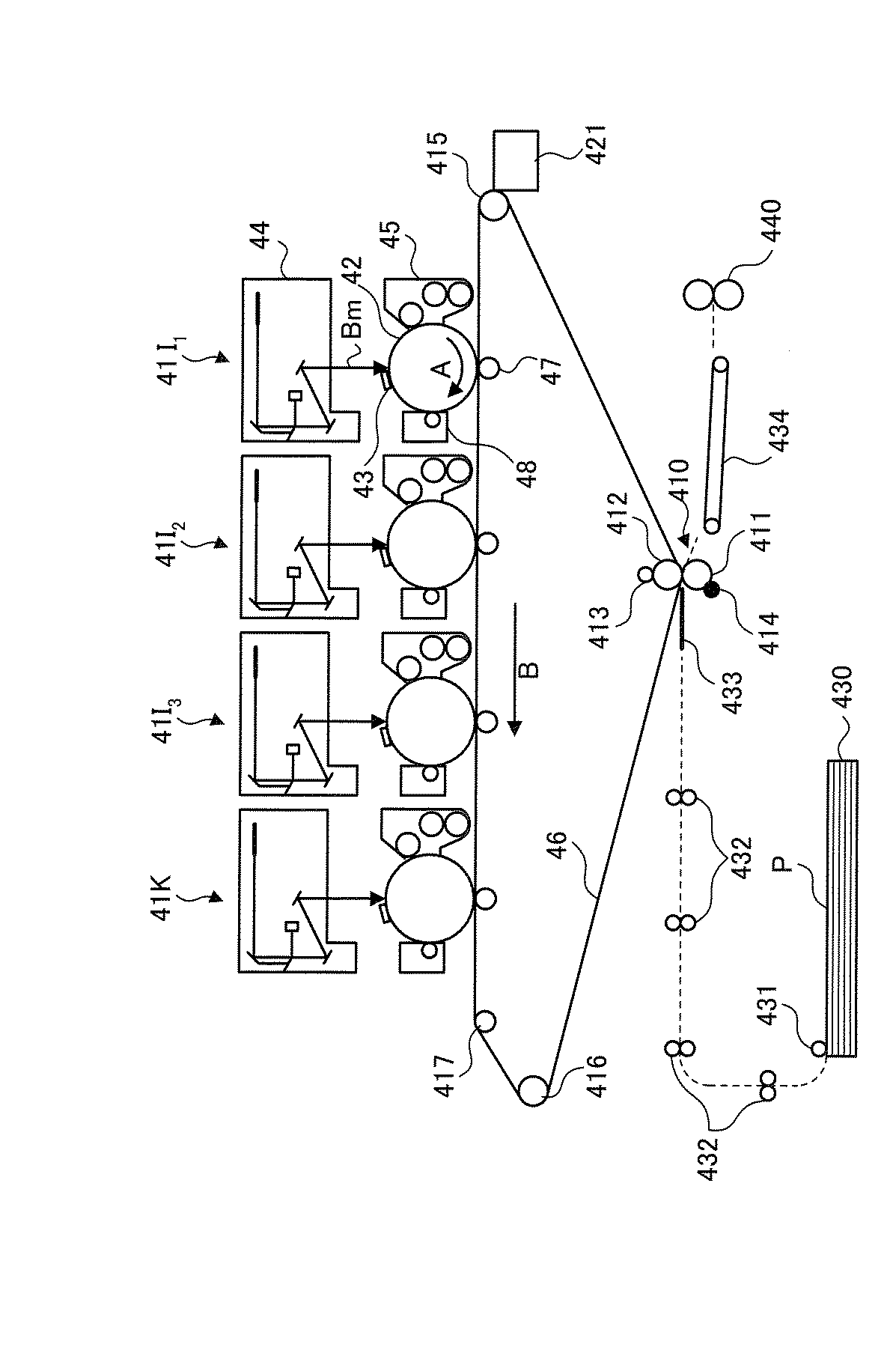
表1に示す結果から、トナー粒子(1)〜(6)(実施例1〜実施例6)は、分光光度計で測定した波長(λ)850nmにおける吸収量が大きいことが分かる。これに対して、トナー粒子(7)(比較例1)は、波長(λ)850nmにおける吸収量が小さいことが分かる。 From the results shown in Table 1, it can be seen that toner particles (1) to (6) (Examples 1 to 6) have a large absorption amount at a wavelength (λ) of 850 nm measured with a spectrophotometer. On the other hand, it can be seen that toner particle (7) (Comparative Example 1) has a small absorption amount at a wavelength (λ) of 850 nm.
100,700…端末装置、200…文書リポジトリ、400…画像形成装置、500…印刷物、600…ペンデバイス DESCRIPTION OF SYMBOLS 100,700 ... Terminal device, 200 ... Document repository, 400 ... Image forming apparatus, 500 ... Printed matter, 600 ... Pen device
Claims (8)
前記画像形成手段により形成した画像を媒体に転写する転写手段と
を備えることを特徴とする画像形成装置。 Image forming means for forming an image using a recording material having an absorption wavelength in the near-infrared light region, the absorption curve being changed by heat, and reading is restricted;
An image forming apparatus comprising: transfer means for transferring an image formed by the image forming means to a medium.
前記複数の熱変換材料は、200℃以上の異なる温度でそれぞれ分解することを特徴とする請求項1記載の画像形成装置。 The recording material includes a plurality of heat conversion materials,
The image forming apparatus according to claim 1, wherein the plurality of heat conversion materials are decomposed at different temperatures of 200 ° C. or more.
常温における近赤外線による前記コード画像の読み取りを可能にし、且つ、少なくとも200℃において当該コード画像の読み取りを制限する熱変換材料
を含むことを特徴とする記録材。 A recording material used for printing a code image and a document image on a medium, for printing the code image,
A recording material comprising a heat conversion material that enables reading of the code image by near infrared rays at room temperature and restricts reading of the code image at least at 200 ° C.
Priority Applications (1)
| Application Number | Priority Date | Filing Date | Title |
|---|---|---|---|
| JP2006018917A JP2007199474A (en) | 2006-01-27 | 2006-01-27 | Image forming apparatus and recording material |
Applications Claiming Priority (1)
| Application Number | Priority Date | Filing Date | Title |
|---|---|---|---|
| JP2006018917A JP2007199474A (en) | 2006-01-27 | 2006-01-27 | Image forming apparatus and recording material |
Publications (1)
| Publication Number | Publication Date |
|---|---|
| JP2007199474A true JP2007199474A (en) | 2007-08-09 |
Family
ID=38454137
Family Applications (1)
| Application Number | Title | Priority Date | Filing Date |
|---|---|---|---|
| JP2006018917A Pending JP2007199474A (en) | 2006-01-27 | 2006-01-27 | Image forming apparatus and recording material |
Country Status (1)
| Country | Link |
|---|---|
| JP (1) | JP2007199474A (en) |
Cited By (3)
| Publication number | Priority date | Publication date | Assignee | Title |
|---|---|---|---|---|
| JP2010117736A (en) * | 2010-03-04 | 2010-05-27 | Oki Data Corp | Image forming machine |
| US8467101B2 (en) | 2007-09-28 | 2013-06-18 | Oki Data Corporation | Image forming apparatus for adjusting dot size |
| JP2016153924A (en) * | 2016-06-01 | 2016-08-25 | 株式会社東芝 | Decolorization device and image decolorization system |
-
2006
- 2006-01-27 JP JP2006018917A patent/JP2007199474A/en active Pending
Cited By (5)
| Publication number | Priority date | Publication date | Assignee | Title |
|---|---|---|---|---|
| US8467101B2 (en) | 2007-09-28 | 2013-06-18 | Oki Data Corporation | Image forming apparatus for adjusting dot size |
| EP2405305A3 (en) * | 2007-09-28 | 2015-07-01 | Oki Data Corporation | Image forming apparatus |
| EP2042936B1 (en) * | 2007-09-28 | 2016-08-17 | Oki Data Corporation | Image forming apparatus |
| JP2010117736A (en) * | 2010-03-04 | 2010-05-27 | Oki Data Corp | Image forming machine |
| JP2016153924A (en) * | 2016-06-01 | 2016-08-25 | 株式会社東芝 | Decolorization device and image decolorization system |
Similar Documents
| Publication | Publication Date | Title |
|---|---|---|
| KR101292631B1 (en) | Electrophotographic toner, invisible electrophotographic toner, electrophotographic developer, toner cartridge, process cartridge, and image formation apparatus | |
| JP2020190724A (en) | Toner, toner container, developer, developing device, process cartridge, and image forming device | |
| JP4305203B2 (en) | Toner for electrophotography and image forming method using the same | |
| JP4708717B2 (en) | Toner production method | |
| US8722292B2 (en) | Electrostatic image developing toner, invisible information toner, electrostatic image developer, process cartridge and image formation apparatus | |
| JP7547819B2 (en) | Toner for developing electrostatic images and image forming method | |
| JP4715691B2 (en) | Toner for developing electrostatic charge, developer for developing electrostatic charge using the same, developer cartridge for developing electrostatic charge, and image forming apparatus | |
| JP2007219103A (en) | Electrophotographic toner, electrophotographic developer and image forming method | |
| JP2007199474A (en) | Image forming apparatus and recording material | |
| JP2006079017A (en) | Electrophotographic toner, and electrophotographic developer and image forming method using same | |
| JP4321288B2 (en) | Toner for electrophotography | |
| JP4506599B2 (en) | Toner for developing electrostatic image and method for producing the same, toner set, electrostatic image developer and image forming method | |
| JP2005249968A (en) | Electrophotographic toner, electrophotographic developer, and image forming method using them | |
| JP2010271486A (en) | Electrophotographic toner, electrophotographic developer, toner cartridge, process cartridge, and image forming device | |
| JP2012053153A (en) | Electrostatic charge image development toner, electrostatic charge image development developer, toner cartridge, process cartridge, image forming apparatus, image forming method, and reading method of toner image | |
| JP4477446B2 (en) | Toner, two-component developer using the same, and image forming apparatus | |
| JP4604785B2 (en) | Image recording method and toner set for electrophotography | |
| JP4492263B2 (en) | Manufacturing method of color toner for light fixing | |
| JP2022016995A (en) | Toner for static charge image development and image formation method | |
| JP2008039822A (en) | Color toner and image forming apparatus | |
| JP7395992B2 (en) | Toner, toner manufacturing method, toner storage unit, image forming apparatus, and image forming method | |
| CN113820929B (en) | Toner, toner cartridge, and image forming apparatus | |
| JP2013025250A (en) | Light fixing toner, developer, fixing method, fixing device and image formation device | |
| JP5556516B2 (en) | Transparent toner for developing electrostatic image, electrostatic image developer, toner cartridge, process cartridge, image forming method, and image forming apparatus | |
| JP2008083643A (en) | Toner for electrostatic charge image development, toner cartridge and image forming apparatus |