JP2007187747A - Lens drive module, camera module, and electronic equipment - Google Patents
Lens drive module, camera module, and electronic equipment Download PDFInfo
- Publication number
- JP2007187747A JP2007187747A JP2006003975A JP2006003975A JP2007187747A JP 2007187747 A JP2007187747 A JP 2007187747A JP 2006003975 A JP2006003975 A JP 2006003975A JP 2006003975 A JP2006003975 A JP 2006003975A JP 2007187747 A JP2007187747 A JP 2007187747A
- Authority
- JP
- Japan
- Prior art keywords
- lens frame
- movable lens
- movable
- housing
- driving module
- Prior art date
- Legal status (The legal status is an assumption and is not a legal conclusion. Google has not performed a legal analysis and makes no representation as to the accuracy of the status listed.)
- Pending
Links
Images


Landscapes
- Lens Barrels (AREA)
- Studio Devices (AREA)
Abstract
Description
本発明は、フォーカシングやズーミングを行うために用いられるレンズ駆動モジュール及びこの装置を備えて構成されるカメラモジュールに関する。 The present invention relates to a lens driving module used for performing focusing and zooming, and a camera module configured by including this device.
また、本発明は、このカメラモジュールが搭載される電子機器、例えば、携帯電子機器であるカード形デジタルカメラやカメラ付き携帯電話等に関する。 The present invention also relates to an electronic device in which the camera module is mounted, for example, a card-type digital camera that is a portable electronic device, a mobile phone with a camera, or the like.
従来、ズーム機構を有したカメラをコンパクトにするために、モータと歯車列及びカム筒を用いて鏡筒(レンズ群)を光軸方向に移動させることが知られている。しかし、カム筒を用いて鏡筒(レンズ群)を光軸方向に移動させる技術では、レンズの外径より外側にカム筒を配置するため、鏡筒が大きくなってしまう。一方、歯車列を介してリードスクリューにモータの駆動力を伝達し、リードスクリューの回転により送りナットを介してレンズ群(バレル)を光軸方向に往復移動させる技術が知られている(例えば、特許文献1参照)。 Conventionally, in order to make a camera having a zoom mechanism compact, it is known to move a lens barrel (lens group) in the optical axis direction using a motor, a gear train, and a cam barrel. However, in the technique of moving the lens barrel (lens group) in the optical axis direction using the cam barrel, the cam barrel is arranged outside the outer diameter of the lens, so that the lens barrel becomes large. On the other hand, a technique is known in which a driving force of a motor is transmitted to a lead screw via a gear train, and a lens group (barrel) is reciprocated in the optical axis direction via a feed nut by rotation of the lead screw (for example, Patent Document 1).
近年、デジタルスチルカメラ等の撮像装置においては、携帯性の向上・使い勝手の良化が求められ、装置全体の小型化が行われており、撮像装置に用いられる光学系鏡筒及びレンズの小型化も進められているが、更なる高画質化・高画素化の要望は非常に強く、レンズ移動装置を小型化することによって光学系鏡筒としての小型化が要望される。最近は、デジタルスチルカメラより小型かつ薄型のカメラモジュールを搭載する携帯電話にも、オートフォーカス機能や光学ズーム機能が搭載される状況になり、更なる光学系鏡筒としての薄型化、低コスト化が要求されている。 In recent years, in an imaging apparatus such as a digital still camera, improvement of portability and usability has been demanded, and the entire apparatus has been downsized. Optical system barrels and lenses used in the imaging apparatus have been downsized. However, there is a strong demand for higher image quality and higher pixels, and there is a demand for downsizing the optical system barrel by downsizing the lens moving device. Recently, mobile phones equipped with camera modules that are smaller and thinner than digital still cameras are also equipped with autofocus and optical zoom functions, making the optical lens barrel thinner and lower in cost. Is required.
近年の小型軽量化、更には高画質化等の要望に対し、駆動機構の省スペース化とレンズの移動精度の向上との両立が高次元で求められているのが現状であり、少ないスペース、即ち、撮像装置の小形化を図りながらレンズの移動精度が向上できる技術が求められているのが実情である。 In response to the recent demands for smaller and lighter, higher image quality, etc., it is currently required to have both a space saving drive mechanism and improved lens movement accuracy at a high level. That is, there is a need for a technique that can improve the movement accuracy of the lens while reducing the size of the imaging device.
例えば、レンズ駆動機構において、レンズ枠をスラスト方向、ラジアル方向、あおり方向にがたなく支持する構造として、従来は、複数の弾性部材や特殊な弾性部材を用いる構造や、引張りばねを用いて所望の方向に部材を引張る構造が知られている(例えば、特許文献2、特許文献3、特許文献4等参照)。 For example, in a lens driving mechanism, as a structure that supports a lens frame in a thrust direction, a radial direction, and a tilt direction, a structure that uses a plurality of elastic members or special elastic members, or a tension spring is conventionally used. A structure in which a member is pulled in the direction is known (see, for example, Patent Document 2, Patent Document 3, Patent Document 4).
しかし、複数の弾性部材や特殊な弾性部材を用いたり、引張りばねを用いた場合、大きなスペースを必要とし、小形化には適していない問題があった。また、特殊な弾性部材を用いた場合、コストが嵩み小形化に適用した場合には組み立てが難しくなる問題があった。
本発明は上記状況に鑑みてなされたもので、機器の小形化とレンズの移動精度の確保を高次元で両立することができるレンズ駆動モジュール及びカメラモジュールを提供することを目的とする。 The present invention has been made in view of the above circumstances, and an object of the present invention is to provide a lens driving module and a camera module that can achieve both a reduction in size of the apparatus and a high accuracy in moving the lens.
また、本発明は上記状況に鑑みてなされたもので、機器の小形化とレンズの移動精度の確保を高次元で両立することができるレンズ駆動モジュール及びカメラモジュールを備えた電子機器を提供することを目的とする。 In addition, the present invention has been made in view of the above situation, and provides an electronic device including a lens driving module and a camera module capable of achieving both downsizing of a device and ensuring of lens movement accuracy at a high level. With the goal.
上記目的を達成するための本発明の第1の態様は、光軸方向に沿って往復移動する第1可動レンズ枠と第2可動レンズ枠を備え、第1可動レンズ枠と第2可動レンズ枠とにわたり第1可動レンズ枠と第2可動レンズ枠を離反方向に付勢する付勢手段を備え、第1可動レンズ枠に対する付勢手段の当接位置と第2可動レンズ枠に対する付勢手段の当接位置とが光軸方向から見て互いに偏心していることを特徴とするレンズ駆動モジュールにある。 In order to achieve the above object, a first aspect of the present invention includes a first movable lens frame and a second movable lens frame that reciprocate along the optical axis direction, and the first movable lens frame and the second movable lens frame. Urging means for urging the first movable lens frame and the second movable lens frame in the direction away from each other, the contact position of the urging means with respect to the first movable lens frame and the urging means for the second movable lens frame. In the lens driving module, the contact positions are decentered from each other when viewed from the optical axis direction.
第1の態様では、一つの付勢手段により第1可動レンズ枠と第2可動レンズ枠のスラスト方向とラジアル方向のがたつきを防止することができる。 In the first aspect, it is possible to prevent the first movable lens frame and the second movable lens frame from rattling in the thrust direction and the radial direction by one biasing unit.
そして、本発明の第2の態様は、第1の態様に記載のレンズ駆動モジュールにおいて、付勢手段は圧縮コイルばねであることを特徴とするレンズ駆動モジュールにある。 A second aspect of the present invention is the lens driving module according to the first aspect, wherein the urging means is a compression coil spring.
第2の態様では、一つの圧縮コイルばねにより第1可動レンズ枠と第2可動レンズ枠のスラスト方向とラジアル方向のがたつきを防止することができる。 In the second aspect, it is possible to prevent the first movable lens frame and the second movable lens frame from shaking in the thrust direction and the radial direction with one compression coil spring.
また、本発明の第3の態様は、第1または第2の態様に記載のレンズ駆動モジュールにおいて、第1可動レンズ枠を往復移動させる第1モータを備えると共に、第2可動レンズ枠を往復移動させる第2モータを備え、第1モータ及び第2モータで第1可動レンズ枠と第2可動レンズ枠とを独立して移動させることでズーム用とフォーカス用とを独立に駆動することを特徴とするレンズ駆動モジュールにある。 According to a third aspect of the present invention, the lens driving module according to the first or second aspect includes a first motor that reciprocates the first movable lens frame, and reciprocates the second movable lens frame. A second motor for driving the zoom and the focus independently by independently moving the first movable lens frame and the second movable lens frame by the first motor and the second motor. To the lens drive module.
第3の態様では、第1モータ及び第2モータにより第1の可動レンズ枠及び第2の可動レンズ枠をがたつきなく往復移動させることができる。 In the third aspect, the first movable lens frame and the second movable lens frame can be reciprocated without rattling by the first motor and the second motor.
また、本発明の第4の態様は、第3の態様に記載のレンズ駆動モジュールにおいて、第1可動レンズ枠を検知する第1検知手段を第1可動レンズ枠の基準位置に設けると共に、第2可動レンズ枠の基準位置を検知すると共に第1可動レンズ枠を検知する第2検知手段を第2可動レンズ枠の基準位置に設け、第1検知手段と第2検知手段の検知情報に基づいて第1検知手段と第2検知手段の間隔を導出して第1可動レンズ枠と第2可動レンズ枠の相対位置を把握する制御手段を備えたことを特徴とするレンズ駆動モジュールにある。 According to a fourth aspect of the present invention, in the lens driving module according to the third aspect, the first detection means for detecting the first movable lens frame is provided at the reference position of the first movable lens frame, and the second A second detection means for detecting the reference position of the movable lens frame and detecting the first movable lens frame is provided at the reference position of the second movable lens frame, and the second detection means is based on the detection information of the first detection means and the second detection means. The lens driving module includes a control unit that derives an interval between the first detection unit and the second detection unit and grasps a relative position between the first movable lens frame and the second movable lens frame.
第4の態様では、機器の個体差に拘わらず常に第1可動レンズ枠と第2可動レンズ枠の位置関係を正確に把握することができる。 In the fourth aspect, the positional relationship between the first movable lens frame and the second movable lens frame can always be accurately grasped regardless of individual differences between devices.
また、本発明の第5の態様は、第3または第4の態様に記載のレンズ駆動モジュールにおいて、第1可動レンズ枠には光軸方向に延びる第1送りねじ軸が螺合すると共に、第2可動レンズ枠には光軸方向に延びる第2送りねじ軸が螺合し、第1モータの駆動力を第1送りねじ軸に伝達する第1動力伝達手段を備え、第2モータの駆動力を第2送りねじ軸に伝達する第2動力伝達手段を備えたことを特徴とするレンズ駆動モジュールにある。 According to a fifth aspect of the present invention, in the lens driving module according to the third or fourth aspect, the first feed screw shaft extending in the optical axis direction is screwed into the first movable lens frame, A second feed screw shaft extending in the optical axis direction is screwed onto the two movable lens frames, and includes first power transmission means for transmitting the drive force of the first motor to the first feed screw shaft, and the drive force of the second motor. A lens driving module comprising second power transmission means for transmitting the power to the second feed screw shaft.
第5の態様では、第1送りねじ軸及び第2送りねじ軸の駆動により第1可動レンズ枠及び第2可動レンズ枠をがたつきなく往復移動させることができる。 In the fifth aspect, the first movable lens frame and the second movable lens frame can be reciprocated without rattling by driving the first feed screw shaft and the second feed screw shaft.
また、本発明の第6の態様は、第5の態様に記載のレンズ駆動モジュールにおいて、第1送りねじ軸を軸方向の一方側に付勢する第1ねじ付勢手段を備えると共に、第2送りねじ軸を軸方向の一方向に付勢する第2ねじ付勢手段を備えたことを特徴とするレンズ駆動モジュールにある。 According to a sixth aspect of the present invention, in the lens driving module according to the fifth aspect, the first drive screw urging means for urging the first feed screw shaft toward one side in the axial direction is provided. A lens driving module comprising second screw urging means for urging the feed screw shaft in one axial direction.
第6の態様では、第1送りねじ軸及び第2送りねじ軸の軸方向のがたつきをなくすことができる。 In the sixth aspect, shakiness in the axial direction of the first feed screw shaft and the second feed screw shaft can be eliminated.
また、本発明の第7の態様は、第1〜第6のいずれかの態様に記載のレンズ駆動モジュールにおいて、第1可動レンズ枠の往復移動のみを許容する第1ガイド軸を備えると供に、第2可動レンズ枠の往復移動のみを許容する第2ガイド軸を備えたことを特徴とするレンズ駆動モジュールにある。 Further, according to a seventh aspect of the present invention, in the lens driving module according to any one of the first to sixth aspects, a first guide shaft that allows only the reciprocating movement of the first movable lens frame is provided. The lens driving module includes a second guide shaft that allows only the reciprocating movement of the second movable lens frame.
第7の態様では、第1可動レンズ枠及び第2可動レンズ枠の回転方向の移動を規制することができる。 In the seventh aspect, movement of the first movable lens frame and the second movable lens frame in the rotational direction can be restricted.
また、本発明の第8の態様は、第1〜第7の態様のいずれかに記載のレンズ駆動モジュールにおいて、第1レンズ枠を挟んで第2レンズ枠の反対側の光軸方向の一端側に第1固定レンズ枠を有する第1ハウジングを設け、第2レンズ枠を挟んで第1レンズ枠の反対側の光軸方向の他端側に第2固定レンズ枠を有する第2ハウジングを設け、第1ハウジング及び第2ハウジングには互いに嵌合する壁部が形成され、第1ハウジングと第2ハウジングを嵌合した際に光軸方向に交差する方向に窓部が形成されることを特徴とするレンズ駆動モジュールにある。 According to an eighth aspect of the present invention, in the lens driving module according to any one of the first to seventh aspects, one end side in the optical axis direction on the opposite side of the second lens frame across the first lens frame. A first housing having a first fixed lens frame is provided, and a second housing having a second fixed lens frame is provided on the other end side in the optical axis direction on the opposite side of the first lens frame across the second lens frame, The first housing and the second housing are formed with wall portions that fit together, and a window portion is formed in a direction that intersects the optical axis direction when the first housing and the second housing are fitted. To the lens drive module.
第8の態様では、モジュールの強度を増すことができ、窓部により光学系や駆動機構のメンテナンスを行うことができる。 In the eighth aspect, the strength of the module can be increased, and maintenance of the optical system and the drive mechanism can be performed by the window portion.
上記目的を達成するための本発明の第9の態様は、光軸方向に沿って往復移動する可動レンズ枠を備え、ハウジング側と可動レンズ枠とにわたり可動レンズ枠を一方向に付勢する付勢手段を備え、可動レンズ枠に対する付勢手段の当接位置とハウジング側に対する付勢手段の当接位置とが光軸方向から見て互いに偏心していることを特徴とするレンズ駆動モジュールにある。 In order to achieve the above object, a ninth aspect of the present invention includes a movable lens frame that reciprocates along the optical axis direction, and biases the movable lens frame in one direction across the housing side and the movable lens frame. The lens driving module includes a biasing unit, and a contact position of the biasing unit with respect to the movable lens frame and a contact position of the biasing unit with respect to the housing side are decentered from each other when viewed from the optical axis direction.
第9の態様では、一つの付勢手段により可動レンズ枠をスラスト方向とラジアル方向のがたつきを防止することができる。 In the ninth aspect, it is possible to prevent the movable lens frame from rattling in the thrust direction and the radial direction by one urging means.
上記目的を達成するための本発明の第10の態様は、第1〜第9のいずれかの態様に記載のレンズ駆動モジュールに撮像素子を備えたことを特徴とするカメラモジュールにある。 To achieve the above object, a tenth aspect of the present invention resides in a camera module characterized in that the lens driving module according to any one of the first to ninth aspects includes an imaging device.
第10の態様では、一つの付勢手段により可動レンズ枠をスラスト方向とラジアル方向のがたつきを防止することができるレンズ駆動モジュールを備えたカメラモジュールとすることができる。 In the tenth aspect, the movable lens frame can be a camera module including a lens driving module capable of preventing the shaking in the thrust direction and the radial direction by a single urging unit.
上記目的を達成するための本発明の第11の態様は、第10の態様に記載のカメラモジュールを備えたことを特徴とする電子機器にある。 To achieve the above object, an eleventh aspect of the present invention resides in an electronic device comprising the camera module according to the tenth aspect.
第11の態様では、一つの付勢手段により可動レンズ枠をスラスト方向とラジアル方向のがたつきを防止することができるレンズ駆動モジュールを有するカメラモジュールを備えた電子機器とすることができる。 In the eleventh aspect, it is possible to provide an electronic apparatus including a camera module having a lens driving module that can prevent the movable lens frame from rattling in the thrust direction and the radial direction by one urging unit.
本発明のレンズ駆動モジュール及びカメラモジュールは、機器の小形化とレンズの移動精度の確保を高次元で両立することができるレンズ駆動モジュール及びカメラモジュールとなる。 The lens driving module and the camera module according to the present invention are a lens driving module and a camera module that can achieve both downsizing of the apparatus and ensuring of the movement accuracy of the lens at a high level.
また、本発明の電子機器は、機器の小形化とレンズの移動精度の確保を高次元で両立することができるレンズ駆動モジュール及びカメラモジュールを備えた電子機器となる。 In addition, the electronic device of the present invention is an electronic device including a lens driving module and a camera module that can achieve both a reduction in the size of the device and securing of lens movement accuracy at a high level.
図1は本発明の第1実施形態例に係るレンズ駆動モジュールを備えたカメラモジュールの全体構成図、図2はカメラモジュールの分解斜視図、図3、図4はカメラモジュールの平面図、図5は図3中のV−V線矢視図、図6は図3中のVI−VI線矢視図、図7は図4中のVII−VII線矢視図、図8はレンズ枠の平面図、図9は第1レンズ枠の平面図、図10は第2レンズ枠の平面図、図11は第2ハウジングの斜視図、図12はレンズ枠を除く部材を保持した状態の第2ハウジングの斜視図、図13は第1ハウジング及び基板を嵌合した状態の斜視図、図14は図13中の基板側からの斜視図、図15はカメラモジュールを有する電子機器のブロック構成図、図16はレンズ枠の位置関係を検出している状態の説明図である。 1 is an overall configuration diagram of a camera module including a lens driving module according to a first embodiment of the present invention, FIG. 2 is an exploded perspective view of the camera module, FIGS. 3 and 4 are plan views of the camera module, and FIG. Is a view taken along line VV in FIG. 3, FIG. 6 is a view taken along line VI-VI in FIG. 3, FIG. 7 is a view taken along line VII-VII in FIG. 4, and FIG. 9 is a plan view of the first lens frame, FIG. 10 is a plan view of the second lens frame, FIG. 11 is a perspective view of the second housing, and FIG. 12 is a second housing in a state where members excluding the lens frame are held. FIG. 13 is a perspective view of a state in which the first housing and the substrate are fitted, FIG. 14 is a perspective view from the substrate side in FIG. 13, and FIG. 15 is a block configuration diagram of an electronic apparatus having a camera module. 16 is an explanatory diagram of a state in which the positional relationship of the lens frame is detected.
また、図17は他の実施形態例に係る送りねじ軸の斜視図である。更に、図18は本発明の他の実施形態例に係るカメラモジュールの断面図である。 FIG. 17 is a perspective view of a feed screw shaft according to another embodiment. FIG. 18 is a cross-sectional view of a camera module according to another embodiment of the present invention.
図1乃至図18に示したカメラモジュールは、電子機器として、携帯電話のカメラ、PCのカメラ等としてスペースに限りがある部位に適用して好適である。 The camera module shown in FIG. 1 to FIG. 18 is suitable for application to a part having limited space as a mobile phone camera, a PC camera, or the like as an electronic device.
図1、図2に示すように、カメラモジュール200の筐体として、被写体側の固定レンズが備えられる第1ハウジング201と、撮像素子及び撮像素子側の固定レンズが備えられる第2ハウジング202とを有している。第1ハウジング201及び第2ハウジング202にはそれぞれ縦壁部203が備えられ、縦壁部203が互いに嵌合して一つの筐体を構成するようになっている。縦壁部203を介して第1ハウジング201と第2ハウジング202を嵌合することにより、光軸方向に交差する方向、即ち、側面部に窓部204が形成されるようになっている。筐体には回路ブロック205、補強板206等が取り付けられ、窓部204はカバー207で塞がれるようになっている。
As shown in FIGS. 1 and 2, as a housing of the
図2に示すように、第1ハウジング201及び第2ハウジング202から構成される筐体には、カメラモジュール200の構成部材である、第1可動レンズ枠211、第2可動レンズ枠212、第1モータ213(ステッピングモータ)、第2モータ214(ステッピングモータ)、第1送りねじ215、第2送りねじ216、第1ガイド軸217、第2ガイド軸218、付勢手段としてのコイルばね219、第1板ばね220、第2板ばね221、第1検知手段としての第1フォトインタラプタ222、第2フォトインタラプタ223等が主要構成部材として収容保持されている。
As shown in FIG. 2, a housing constituted by the
図3乃至図14に基づいてカメラモジュール200を具体的に説明する。
The
図3、図5に示すように、第2ハウジング202のレンズ枠(第2固定レンズ枠)には第2固定レンズ群225が設けられ、第2固定レンズ群225の後面(図5中下側)の基板209上には撮像素子(CCDカメラ等)226が設けられている。第1ハウジング201のレンズ枠(第1固定レンズ枠)には第1固定レンズ群210が設けられ、第1固定レンズ群210と第2固定レンズ群225は光軸が同軸状に配置されている。
As shown in FIGS. 3 and 5, the lens frame (second fixed lens frame) of the
第2固定レンズ群225を対角状態に挟んで第2ハウジング202には第1ガイド軸217及び第2ガイド軸218の下端部が支持されている。第1ガイド軸217及び第2ガイド軸218の上端部は第1ハウジング201に支持され、第1ガイド軸217及び第2ガイド軸218が第2固定レンズ群225を挟んで筐体内に立設さている。
The lower ends of the
第1ガイド軸217には第1可動レンズ枠211が摺動自在に支持され、摺動部は軸方向に長さを持った支持部位227となっている。このため、第1可動レンズ枠211の傾きが防止される。また、第1可動レンズ枠211は貫通孔228を介して第2ガイド軸218に貫通されている。そして、第1可動レンズ枠211には第1可動レンズ群229が設けられている。第2ガイド軸218には第2可動レンズ枠212が摺動自在に支持され、摺動部は軸方向に長さを持った支持部位231となっている。このため、第2可動レンズ枠212の傾きが防止される。また、第2可動レンズ枠212は貫通孔232を介して第1ガイド軸217に貫通されている。そして、第2可動レンズ枠212には第2可動レンズ群233が設けられている。
The first
つまり、第1可動レンズ枠211は第1ガイド軸217によって上下の往復移動のみが許容され、第2可動レンズ枠212は第2ガイド軸218によって上下の往復移動のみが許容されている。そして、第1可動レンズ枠211は貫通孔228が第2ガイド軸218を貫通することにより回転方向の動きが規制され、第2可動レンズ枠212は貫通孔232が第1ガイド軸217を貫通することにより回転方向の動きが規制されている。
That is, the first
図5、図7に示すように、第1可動レンズ枠211の支持部位227に対応する部位、即ち、貫通孔232の部位における第2可動レンズ枠212には第2逃げ部234が設けられ、第2逃げ部234により第1可動レンズ枠211の支持部位227が軸方向で第2可動レンズ枠212と一部重複するようにされている。また、第2可動レンズ枠212の支持部位231に対応する部位、即ち、貫通孔228の部位における第1可動レンズ枠211には第1逃げ部235が設けられ、第1逃げ部235により第2可動レンズ枠212の支持部位231が軸方向で第1可動レンズ枠211と一部重複するようにされている。
As shown in FIGS. 5 and 7, the second
このため、第1ガイド軸217に対する第1可動レンズ枠211の支持部位227を軸方向に長くとって安定性を高めた場合でも、第2可動レンズ枠212が軸方向で干渉することがなくなると共に、第2ガイド軸218に対する第2可動レンズ枠212の支持部位231を長くとって安定性を高めた場合でも、第1可動レンズ枠211が軸方向で干渉することがなくなり、支持長さを十分に確保しても第1可動レンズ枠211及び第2可動レンズ枠212の移動範囲を拡大することができ、第1可動レンズ枠211及び第2可動レンズ枠212を接近させることができる。
Therefore, even when the
図2に示すように、第2ハウジング202を構成する縦壁部203によりフォトインタラプタ取付け部236が形成され、フォトインタラプタ取付け部236には、第1フォトインタラプタ222、第2フォトインタラプタ223が位置決めされ、第1フォトインタラプタ222、第2フォトインタラプタ223に固定された補強板206が第2ハウジング202の壁面に固定される。フォトインタラプタ取付け部236に第1フォトインタラプタ222、第2フォトインタラプタ223が固定されることで、第1フォトインタラプタ222、第2フォトインタラプタ223は第2ハウジング202の所定位置に容易に位置決めされて保持される。
As shown in FIG. 2, the photo
一方、図2、図5、図9に示すように、第1可動レンズ枠211の第1フォトインタラプタ222側には第1遮蔽部237が設けられ、第1フォトインタラプタ222の位置で第1遮蔽部237が通過することで第1可動レンズ枠211の所定位置が検出される。第1可動レンズ枠211の第2フォトインタラプタ223側には補助遮蔽部238が設けられている。つまり、第1可動レンズ枠211の両側には第1遮蔽部237及び補助遮蔽部238が設けられている。
On the other hand, as shown in FIGS. 2, 5, and 9, a
また、図2、図5、図10に示すように、第2可動レンズ枠212の第2フォトインタラプタ223側には第2遮蔽部239が設けられ、第2フォトインタラプタ223の位置で第2遮蔽部239が通過することで第2可動レンズ枠212の所定位置が検出される。また、第2フォトインタラプタ223の位置で第1可動レンズ枠211の補助遮蔽部238が通過することで第1可動レンズ枠211の所定位置が第2フォトインタラプタ223の位置でも検出される。
2, 5, and 10, a
図2に示すように、第2ハウジング202を構成する縦壁部203によりモータ取付け部241が形成され、モータ取付け部241には第1モータ213、第2モータ214が固定される。モータ取付け部241に第1モータ213、第2モータ214が固定されることで、第1モータ213、第2モータ214は第2ハウジング202の所定位置に容易に位置決めされて保持される。
As shown in FIG. 2, a
図6、図7に示すように、第1固定レンズ群210及び第2固定レンズ群225の光路開口の両外側における第1ハウジング201と第2ハウジング202とにわたり、レンズ群の光軸方向(図中上下方向)に延びる第1送りねじ215、第2送りねじ216が回転自在に支持されている。第1送りねじ215のねじ部242には第1可動レンズ枠211の螺合部243が螺合し、第2送りねじ216のねじ部244には第2可動レンズ枠212の螺合部245が螺合している。
As shown in FIGS. 6 and 7, the optical axis direction of the lens group extends across the
第1送りねじ215の下端には入力歯車246が設けられ、第2送りねじ216の下端には入力歯車247が設けられている。一方、第1モータ213には出力歯車248が設けられ、第2モータ214には出力歯車249が設けられている。第1モータ213の出力歯車248と第1送りねじ215の入力歯車246には伝達歯車250が噛み合い、第2モータ214の出力歯車249と第2送りねじ216の入力歯車247には伝達歯車251が噛み合っている。図中の符号で252は伝達歯車250、251を支持する輪列受である。
An
つまり、第1モータ213の駆動により、出力歯車248、伝達歯車250及び入力歯車246を介して第1送りねじ215が回転し、第1送りねじ215の回転によりねじ部242に螺合する螺合部243を介して第1可動レンズ枠211が上下方向に往復移動する。また、第2モータ214の駆動により、出力歯車249、伝達歯車251及び入力歯車247を介して第2送りねじ216が回転し、第2送りねじ216の回転によりねじ部244に螺合する螺合部245を介して第2可動レンズ枠212が上下方向に往復移動する。このため、第1可動レンズ枠211及び第2可動レンズ枠212がそれぞれ独立して上下方向に往復移動し、第1可動レンズ群229及び第2可動レンズ群233が第1固定レンズ群210及び第2固定レンズ群225の間で独立して任意の位置に動作されるようになっている。これにより、ズーミング及びフォーカシングを独立して行うことができる。
That is, when the
尚、第1送りねじ215及び第2送りねじ216の下端に入力歯車246、247がそれぞれ取り付けられているが、図17に示すように、スリップ機構を有する入力歯車291を適用することも可能である。即ち、入力歯車291には逃げ溝292が形成され、所定の回転力が働くと相対回転できる状態の支持穴293に第1送りねじ215及び第2送りねじ216の下端が取り付けられている。
The input gears 246 and 247 are attached to the lower ends of the
このため、第1送りねじ215の回転が規制された状態で入力歯車291に回転力が伝わると、第1送りねじ215及び第2送りねじ216が支持穴293に対して相対的に回転し、入力歯車291の回転力が第1送りねじ215及び第2送りねじ216に伝わることがない。このため、無理な力が入力歯車291の取付き部に働くことがなくなり、駆動機構の破損を防止することが可能になる。
For this reason, when the rotational force is transmitted to the
一方、図6、図7に示すように、第2可動レンズ枠212の螺合部245は光軸方向の上側に突出して形成され、螺合部245に対応する第1レンズ枠211には逃げ部253が形成されている。このため、第2可動レンズ枠212の螺合部245と第1レンズ枠211が光軸方向で一部が重複した状態になっている。
On the other hand, as shown in FIGS. 6 and 7, the threaded
このため、螺合部245で第1可動レンズ枠211と第2可動レンズ枠212が軸方向に干渉することがなくなり、第1可動レンズ枠211及び第2可動レンズ枠212の移動範囲を拡大することができる。また、螺合部245は光軸方向の上側に突出して形成されているので、第2可動レンズ枠212を第2送りねじ216の最下端まで下降させても、入力歯車247に干渉することがなく、更に、第2可動レンズ枠212の移動範囲を拡大することができる。
For this reason, the first
図6、図7に示すように、第1可動レンズ枠211と第2可動レンズ枠212の間には付勢手段としての圧縮コイルばね255が設けられ、圧縮コイルばね255により第1可動レンズ枠211と第2可動レンズ枠212は離反方向(光軸方向:スラスト方向)及び離反方向に交差する方向(光軸方向に交差する方向:ラジアル方向)に付勢されている。
As shown in FIGS. 6 and 7, a
即ち、図9に示すように、第1可動レンズ枠211の下面にはばね案内溝256が形成され、ばね案内溝256は、図中下側が太く上側が細い溝となっている。また、図10に示すように、第2可動レンズ枠212の上面にはばね案内溝257が形成され、ばね案内溝は、図中下側が細く上側が太い溝となっている。ばね案内溝256、257にわたり圧縮コイルばね255を設けることで、図8に示すように、第1可動レンズ枠211の支持部と第2可動レンズ枠212の支持部とが光軸方向で、図中上下がラジアル方向にオフセットされた状態になっている。
That is, as shown in FIG. 9, a
このため、第1可動レンズ枠211と第2可動レンズ枠212は、一つの圧縮コイルばね255により、第1送りねじ215及び第2送りねじ216に対するスラスト方向のがたつきが防止され、第1ガイド軸217及び第2ガイド軸218に対するラジアル方向のがたつき、即ち、貫通孔228、232の第1ガイド軸217及び第2ガイド軸218に対するがたつきが防止される。従って、部品点数を増加させることなく第1可動レンズ枠211と第2可動レンズ枠212の移動を精度良く維持することができる。
For this reason, the first
尚、ばね案内溝256、257は、溝幅が一定の円周溝を偏心して形成することも可能である。
The
上述した実施形態例では、圧縮コイルばね255を設けたレンズ駆動モジュールとして、第1可動レンズ枠211と第2可動レンズ枠212を備えたモジュールを例に挙げて説明したが、可動レンズ枠が一つのレンズ駆動モジュールに上述した圧縮ばねを用いた機構を適用することも可能である。
In the embodiment described above, the module including the first
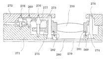
図18には可動レンズ枠が一つのレンズ駆動モジュールに上述した圧縮ばねを用いた機構を適用した例を示してある。 FIG. 18 shows an example in which the above-described mechanism using the compression spring is applied to a lens driving module having a single movable lens frame.
図に示すように、ハウジングとしての地板271と輪列受272とにわたりガイドシャフト273、274が立設され、ガイドシャフト273には可動レンズ枠275が軸方向にのみ移動が許容された状態で支持されている。また、可動レンズ枠275はガイドシャフト274を貫通し、ガイドシャフト274により回転方向の動きが規制されている。また、ハウジングとしての地板271と輪列受272とにわたり送りねじ軸276が回転自在に支持され、送りねじ軸276のねじ部には可動レンズ枠275が螺合している。送りねじ軸276の端部(上端)には入力歯車277が設けられ、駆動歯車278の駆動回転力が伝達歯車260を介して入力歯車277に入力される。駆動歯車278の駆動回転力が入力歯車277に入力されることで、送りねじ軸276が回転して可動レンズ枠275が上下方向に往復移動する。
As shown in the figure, guide
図中の符号で、270は可動レンズ枠275に保持される可動レンズ群、279は基板、280は可動レンズ群270に対向して基板279上に配置される撮像素子である。
In the figure,
そして、可動レンズ枠275と地板271の間には付勢手段としての圧縮コイルばね269が設けられ、圧縮コイルばね269により可動レンズ枠275は上方(光軸方向:スラスト方向)及び光軸方向に交差する方向(ラジアル方向)に付勢されている。
A
即ち、可動レンズ枠275の下面のばね案内溝281と地板271の上面のばね案内溝282は、光軸方向の上下で、ラジアル方向にオフセットされた状態になっている。こんおため、可動レンズ枠275に対する圧縮コイルばね269の支持位置(当接位置)と地板271に対する圧縮コイルばね269の支持位置(当接位置)が偏心した状態になり、一つの圧縮コイルばね269により可動レンズ枠275がスラスト方向及びラジアル方向に付勢される。
That is, the
このため、可動レンズ枠275は、一つの圧縮コイルばね269により送りねじ軸276に対するスラスト方向のがたつきが防止され、ガイドシャフト274に対する貫通部のがたつきが防止される。従って、部品点数を増加させることなく可動レンズ枠275の移動を精度良く維持することができる。
For this reason, the
図1乃至図16に示す実施形態例の説明に戻る。 Returning to the description of the embodiment shown in FIGS.
図2、図7に示すように、第1ガイド軸217の上端には第1板ばね220の一端部が挿入して取り付けられ、第1板ばね220の途中部位には第1送りねじ215のスラスト受け285が挿入して取り付けられている。更に、第1板ばね220の先端(他端部)は第1ハウジング201の内側に設けられた第1押部286により下側(第2ハウジング202側)に押圧されている。また、第2ガイド軸218の上端には第2板ばね221の一端部が挿入して取り付けられ、第2板ばね221の途中部位には第2送りねじ216のスラスト受け287が挿入して取り付けられている。更に、第2板ばね221の先端(他端部)は第1ハウジング201の内側に設けられた第2押部288により下側(第2ハウジング202側)に押圧されている。
As shown in FIGS. 2 and 7, one end of the
つまり、第1板ばね220は第1ガイド軸217の支持部が支点となり、第1押部286により押圧されている部位が力点となり、第1送りねじ215のスラスト受け285の部位が作用点となって、第1送りねじ215が下側に付勢されている。また、第2板ばね221は第2ガイド軸218の支持部が支点となり、第2押部288により押圧されている部位が力点となり、第2送りねじ216のスラスト受け287の部位が作用点となって、第2送りねじ216が下側に付勢されている。
That is, in the
従って、第1板ばね220により第1送りねじ215が軸方向に付勢されてがたつきが防止され、第2板ばね221により第2送りねじ216が軸方向に付勢されてがたつきが防止されているので、軸方向のスペースを要することなく第1送りねじ215及び第2送りねじ216のがたつきを防止することができる。また、第1板ばね220を第1ガイド軸217の上端及びスラスト受け285に挿入すると共に、第2板ばね221を第2ガイド軸218の上端及びスラスト受け287に挿入し(図12参照)、第1ハウジング201を被せることで第1板ばね220及び第2板ばね221が第1押部286及び第2押部288に押圧されて固定される。
Accordingly, the
このため、衝撃に強く、第1板ばね220及び第2板ばね221を固定する工程を省略することができ、第1ハウジング201の内側で固定が完結し、固定用の作業穴等を設ける必要がない。
For this reason, it is strong against impact and the process of fixing the
図11乃至図14に基づいて上述したカメラモジュール200の組み立ての概要を説明する。
An outline of the assembly of the
図11に示すように、第2ハウジング202には窓部204、フォトインタラプタ取付け部236、モータ取付け部241が形成され、第2ハウジング202には第1ガイド軸217及び第2ガイド軸218が備えられている。図12に示すように、モータ取付け部241に第1モータ213及び第2モータ214を位置決め保持し、フォトインタラプタ取付け部236に第1フォトインタラプタ222及び第2フォトインタラプタ223を位置決め保持する。更に、第1送りねじ215、第2送りねじ216等の駆動機構を取り付け、第1板ばね220、第2板ばね221を所定の場所に取り付ける。図13に示すように、第1可動レンズ枠211、第2可動レンズ枠212等を取り付け、第1ハウジング201を嵌合し、回路ブロック205を取り付ける。
As shown in FIG. 11, the
これにより、図13、図14に示すように、窓部204が開口した状態で筐体に駆動機構等が組み付けられる。窓部204を用いて所望のレンズ群の組み付け等を行い、窓部204に、図1に示したカバー207を取り付けてカメラモジュール200とされる。尚、窓部204は対向して筐体の両面に形成されており、図1に示したカバー207が図14に示した窓部204にも取り付けられる。レンズ等の部品のメンテナンスを行う場合、カバー207だけを取り外して第1ハウジング201及び第2ハウジング202からなる筐体の構造はそのままで作業を行う。
As a result, as shown in FIGS. 13 and 14, the drive mechanism and the like are assembled to the housing with the
モータ取付け部241に第1モータ213及び第2モータ214を位置決め保持し、フォトインタラプタ取付け部236に第1フォトインタラプタ222及び第2フォトインタラプタ223を位置決め保持するようにしているので、駆動手段及び検出手段の位置決めと組み立てを容易におこなうことができる。また、縦壁部203を備えた第1ハウジング201及び第2ハウジング202を嵌合して筐体を構成しているので、モジュールの強度を十分に確保することができる。
Since the
上述したカメラモジュール200を適用した電子機器の概要を図15に基づいて説明する。
An outline of an electronic apparatus to which the above-described
図に示すように、レンズ駆動モジュール301は、第1可動レンズ枠211及び第2可動レンズ枠212、第1可動レンズ枠211及び第2可動レンズ枠212の位置を検出する第1フォトインタラプタ222及び第2フォトインタラプタ223、送りねじ等から構成されるレンズ駆動機構302及びレンズ駆動機構303、歯車列等から構成される伝達部材304及び伝達部材305、第1モータ213及び第2モータ214で構成されている。そして、カメラモジュール200は、レンズ駆動モジュール301に撮像素子226を備えたものであり、カメラモジュール200を備えた電子機器306は、モータドライバ311及びモータドライバ312、CPUやメモリを備えた制御部313、撮像素子226からの信号が処理される信号処理部314、撮像画像等を表示する表示部315を備えている。
As shown in the figure, the
上述したレンズ駆動モジュール301には、第1フォトインタラプタ222及び第2フォトインタラプタ223により、第1可動レンズ枠211と第2可動レンズ枠212の相対位置を把握する機能が備えられている。初期に第1フォトインタラプタ222及び第2フォトインタラプタ223により第1可動レンズ枠211と第2可動レンズ枠212の原点を検出してその値に基づいて第1可動レンズ枠211と第2可動レンズ枠212の相対位置を把握することができるが、電源を再投入した時や使用時の衝撃などによる外力に応じて機器の組み付け状態に固体差が生じるため、所望の時期に第1可動レンズ枠211と第2可動レンズ枠212の相対関係を把握することは、長期にわたり高精度にレンズを駆動するために重要である。
The
図16に基づいて第1可動レンズ枠211と第2可動レンズ枠212の相対関係を把握する機能を説明する。
Based on FIG. 16, the function of grasping the relative relationship between the first
図16(a)に示すように、第1可動レンズ枠211が第1可動レンズ枠211の所定位置(原点位置)を検出するための第1フォトインタラプタ222の上方に配され、第2可動レンズ枠212が第2可動レンズ枠212の所定位置(原点位置)を検出するための第2フォトインタラプタ223の下方に配される。
As shown in FIG. 16A, the first
この状態から、図16(b)に示すように、第1可動レンズ枠211を下降させると、第1フォトインタラプタ222の位置で第1可動レンズ枠211の第1遮蔽部237が検出され、第1可動レンズ枠211の原点位置が検出される。更に、図16(c)に示すように、第1可動レンズ枠211を下降させると、第2フォトインタラプタ223の位置で第1可動レンズ枠211の補助遮蔽部238が検出され、第2フォトインタラプタ223の位置の第1可動レンズ枠211の位置状態が検出される。
From this state, as shown in FIG. 16B, when the first
そして、図16(d)に示すように、第1可動レンズ枠211を原点位置まで上昇させて原点位置までの第1モータ213のステップ数等を記憶し、第2フォトインタラプタ223の位置から第1フォトインタラプタ222の位置までの間隔を把握する。次に、第2可動レンズ枠212を上昇させると、第2フォトインタラプタ223の位置で第2可動レンズ枠212の第2遮蔽部239が検出され、第2可動レンズ枠212の原点位置が検出される。
Then, as shown in FIG. 16D, the first
第1可動レンズ枠211の昇降により第2フォトインタラプタ223の位置から第1フォトインタラプタ222の位置までの間隔が把握された状態で、第1可動レンズ枠211が原点位置にある時に第2可動レンズ枠212の原点位置が検出されると、第1可動レンズ枠211と第2可動レンズ枠212の相対関係が把握される。つまり、外力等により機器の組み付け状態に固体差が生じても、個別の機器毎に第1可動レンズ枠211と第2可動レンズ枠212の位置関係を把握することができる。
When the first
このため、個々の機器で第1可動レンズ枠211と第2可動レンズ枠212の相対位置を認識できるようになり、使用状態の違いや、第1フォトインタラプタ222や第2フォトインタラプタ223の取付け位置のばらつき等を含めた誤差を機器毎に認識できるので、第1可動レンズ枠211と第2可動レンズ枠212の移動制御を高い次元で精度良く行うことができる。
For this reason, the relative positions of the first
尚、補助遮蔽部を第2可動レンズ枠212に設けて、第1可動レンズ枠211の原点位置に対する第2可動レンズ枠212の位置を把握することも可能である。
It is also possible to provide an auxiliary shielding part on the second
従って、上述した実施形態例では、第1可動レンズ枠211と第2可動レンズ枠212は、一つの圧縮コイルばね255によりスラスト方向及びラジアル方向に付勢されているので、第1送りねじ215及び第2送りねじ216に対するスラスト方向のがたつきが防止され、第1ガイド軸217及び第2ガイド軸218に対するがたつきが防止される。従って、部品点数を増加させることなく第1可動レンズ枠211と第2可動レンズ枠212の移動を精度良く維持することができる。
Therefore, in the above-described embodiment, the first
本発明は、携帯電子機器、例えばカード形デジタルカメラやカメラ付き携帯電話などに搭載されて、フォーカシングやズーミングを行うために用いられるレンズ駆動モジュール及びこの装置を備えて構成されるカメラモジュールの産業分野で利用することができる。 The present invention relates to a lens driving module mounted on a portable electronic device, such as a card-type digital camera or a camera-equipped mobile phone, and used for focusing and zooming, and an industrial field of a camera module configured by including this device. Can be used.
200 カメラモジュール
201 第1ハウジング
202 第2ハウジング
203 縦壁部
204 窓部
205 回路ブロック
206 補強板
207 カバー
209、279 基板
210 第1固定レンズ群
211 第1可動レンズ枠
212 第2可動レンズ枠
213 第1モータ
214 第2モータ
215 第1送りねじ
216 第2送りねじ
217 第1ガイド軸
218 第2ガイド軸
219 コイルばね
220 第1板ばね
221 第2板ばね
222 第1フォトインタラプタ
223 第2フォトインタラプタ
225 第2固定レンズ群
226、280 撮像素子
227、231 支持部位
228、232 貫通孔
229 第1可動レンズ群
233 第2可動レンズ群
234 第2逃げ部
235 第1逃げ部
236 フォトインタラプタ取付け部
237 第1遮蔽部
238 補助遮蔽部
239 第2遮蔽部
241 モータ取付け部
242、244 ねじ部
243、235 螺合部
246、247、277、291 入力歯車
248、249 出力歯車
250、251、260 伝達歯車
252、272 輪列受
255 圧縮コイルばね
256、257、281、282 ばね案内溝
269 圧縮コイルばね
270 可動レンズ群
271 地板
273、274 ガイドシャフト
275 可動レンズ枠
276 送りねじ軸
278 駆動歯車
285、287 スラスト受け
286 第1押部
288 第2押部
292 逃げ溝
293 支持穴
301 レンズ駆動モジュール
302、303 レンズ駆動機構
304、305 伝達部材
306 電子機器
311、312 モータドライバ
313 制御部
314 信号処理部
315 表示部
200 Camera module 201 First housing 202 Second housing 203 Vertical wall portion 204 Window portion 205 Circuit block 206 Reinforcing plate 207 Cover 209, 279 Substrate 210 First fixed lens group 211 First movable lens frame 212 Second movable lens frame 213 First 1 motor 214 2nd motor 215 1st feed screw 216 2nd feed screw 217 1st guide shaft 218 2nd guide shaft 219 Coil spring 220 1st leaf spring 221 2nd leaf spring 222 1st photo interrupter 223 2nd photo interrupter 225 Second fixed lens group 226, 280 Image sensor 227, 231 Support site 228, 232 Through hole 229 First movable lens group 233 Second movable lens group 234 Second relief portion 235 First relief portion 236 Photo interrupter attachment portion 237 First Shielding part 238 Auxiliary shielding part 239 Second shielding portion 241 Motor mounting portion 242, 244 Screw portion 243, 235 Screwing portion 246, 247, 277, 291 Input gear 248, 249 Output gear 250, 251, 260 Transmission gear 252, 272 Ring train receiver 255 Compression coil Spring 256, 257, 281, 282 Spring guide groove 269 Compression coil spring 270 Movable lens group 271 Base plate 273, 274 Guide shaft 275 Movable lens frame 276 Feed screw shaft 278 Drive gear 285, 287 Thrust receiver 286 First push portion 288 Second Pusher 292 Escape groove 293 Support hole 301 Lens drive module 302, 303 Lens drive mechanism 304, 305 Transmission member 306 Electronic device 311, 312 Motor driver 313 Control unit 314 Signal processing unit 315 Display unit
Claims (11)
付勢手段は圧縮コイルばねであることを特徴とするレンズ駆動モジュール。 The lens driving module according to claim 1,
The lens driving module, wherein the biasing means is a compression coil spring.
第1可動レンズ枠を往復移動させる第1モータを備えると共に、第2可動レンズ枠を往復移動させる第2モータを備え、第1モータ及び第2モータで第1可動レンズ枠と第2可動レンズ枠とを独立して移動させることでズーム用とフォーカス用とを独立に駆動することを特徴とするレンズ駆動モジュール。 The lens driving module according to claim 1 or 2,
A first motor for reciprocating the first movable lens frame and a second motor for reciprocating the second movable lens frame are provided, and the first movable lens frame and the second movable lens frame by the first motor and the second motor. A lens driving module that independently drives zooming and focusing by moving the lens and the lens independently.
第1可動レンズ枠を検知する第1検知手段を第1可動レンズ枠の基準位置に設けると共に、第2可動レンズ枠の基準位置を検知すると共に第1可動レンズ枠を検知する第2検知手段を第2可動レンズ枠の基準位置に設け、第1検知手段と第2検知手段の検知情報に基づいて第1検知手段と第2検知手段の間隔を導出して第1可動レンズ枠と第2可動レンズ枠の相対位置を把握する制御手段を備えたことを特徴とするレンズ駆動モジュール。 The lens driving module according to claim 3,
First detection means for detecting the first movable lens frame is provided at the reference position of the first movable lens frame, and second detection means for detecting the reference position of the second movable lens frame and detecting the first movable lens frame. The first movable lens frame and the second movable lens frame are provided at a reference position of the second movable lens frame, and the first movable lens frame and the second movable frame are derived by deriving an interval between the first detection unit and the second detection unit based on detection information of the first detection unit and the second detection unit. A lens driving module comprising control means for grasping a relative position of a lens frame.
第1可動レンズ枠には光軸方向に延びる第1送りねじ軸が螺合すると共に、第2可動レンズ枠には光軸方向に延びる第2送りねじ軸が螺合し、第1モータの駆動力を第1送りねじ軸に伝達する第1動力伝達手段を備え、第2モータの駆動力を第2送りねじ軸に伝達する第2動力伝達手段を備えたことを特徴とするレンズ駆動モジュール。 The lens driving module according to claim 3 or 4,
A first feed screw shaft extending in the optical axis direction is screwed to the first movable lens frame, and a second feed screw shaft extending in the optical axis direction is screwed to the second movable lens frame to drive the first motor. A lens drive module comprising first power transmission means for transmitting force to the first feed screw shaft, and second power transmission means for transmitting drive force of the second motor to the second feed screw shaft.
第1送りねじ軸を軸方向の一方側に付勢する第1ねじ付勢手段を備えると共に、第2送りねじ軸を軸方向の一方向に付勢する第2ねじ付勢手段を備えたことを特徴とするレンズ駆動モジュール。 The lens driving module according to claim 5, wherein
The first screw urging means for urging the first feed screw shaft in one axial direction and the second screw urging means for urging the second feed screw shaft in one axial direction were provided. Lens drive module characterized by
第1可動レンズ枠の往復移動のみを許容する第1ガイド軸を備えると供に、第2可動レンズ枠の往復移動のみを許容する第2ガイド軸を備えたことを特徴とするレンズ駆動モジュール。 In the lens drive module according to any one of claims 1 to 6,
A lens driving module comprising a first guide shaft that allows only reciprocation of the first movable lens frame, and a second guide shaft that allows only reciprocation of the second movable lens frame.
第1レンズ枠を挟んで第2レンズ枠の反対側の光軸方向の一端側に第1固定レンズ枠を有する第1ハウジングを設け、第2レンズ枠を挟んで第1レンズ枠の反対側の光軸方向の他端側に第2固定レンズ枠を有する第2ハウジングを設け、第1ハウジング及び第2ハウジングには互いに嵌合する壁部が形成され、第1ハウジングと第2ハウジングを嵌合した際に光軸方向に交差する方向に窓部が形成されることを特徴とするレンズ駆動モジュール。 In the lens drive module according to any one of claims 1 to 7,
A first housing having a first fixed lens frame is provided on one end side in the optical axis direction on the opposite side of the second lens frame across the first lens frame, and on the opposite side of the first lens frame across the second lens frame. A second housing having a second fixed lens frame is provided on the other end side in the optical axis direction. The first housing and the second housing are formed with wall portions that fit together, and the first housing and the second housing are fitted. And a window portion is formed in a direction crossing the optical axis direction.
Priority Applications (1)
| Application Number | Priority Date | Filing Date | Title |
|---|---|---|---|
| JP2006003975A JP2007187747A (en) | 2006-01-11 | 2006-01-11 | Lens drive module, camera module, and electronic equipment |
Applications Claiming Priority (1)
| Application Number | Priority Date | Filing Date | Title |
|---|---|---|---|
| JP2006003975A JP2007187747A (en) | 2006-01-11 | 2006-01-11 | Lens drive module, camera module, and electronic equipment |
Publications (1)
| Publication Number | Publication Date |
|---|---|
| JP2007187747A true JP2007187747A (en) | 2007-07-26 |
Family
ID=38342977
Family Applications (1)
| Application Number | Title | Priority Date | Filing Date |
|---|---|---|---|
| JP2006003975A Pending JP2007187747A (en) | 2006-01-11 | 2006-01-11 | Lens drive module, camera module, and electronic equipment |
Country Status (1)
| Country | Link |
|---|---|
| JP (1) | JP2007187747A (en) |
Cited By (4)
| Publication number | Priority date | Publication date | Assignee | Title |
|---|---|---|---|---|
| WO2009028140A1 (en) * | 2007-08-30 | 2009-03-05 | Panasonic Corporation | Lens barrel |
| KR101095108B1 (en) | 2010-03-23 | 2011-12-16 | 삼성전기주식회사 | Camera module |
| CN112230364A (en) * | 2020-09-29 | 2021-01-15 | 常州市瑞泰光电有限公司 | Optical module driving device, image pickup device, and portable electronic apparatus |
| CN116055832A (en) * | 2021-10-28 | 2023-05-02 | 维沃移动通信有限公司 | Camera module and electronic equipment |
-
2006
- 2006-01-11 JP JP2006003975A patent/JP2007187747A/en active Pending
Cited By (7)
| Publication number | Priority date | Publication date | Assignee | Title |
|---|---|---|---|---|
| WO2009028140A1 (en) * | 2007-08-30 | 2009-03-05 | Panasonic Corporation | Lens barrel |
| US7864460B2 (en) | 2007-08-30 | 2011-01-04 | Panasonic Corporation | Lens barrel |
| JP5258770B2 (en) * | 2007-08-30 | 2013-08-07 | パナソニック株式会社 | Lens barrel |
| KR101095108B1 (en) | 2010-03-23 | 2011-12-16 | 삼성전기주식회사 | Camera module |
| CN112230364A (en) * | 2020-09-29 | 2021-01-15 | 常州市瑞泰光电有限公司 | Optical module driving device, image pickup device, and portable electronic apparatus |
| CN112230364B (en) * | 2020-09-29 | 2023-11-14 | 常州市瑞泰光电有限公司 | Optical module driving device, image pickup device, and portable electronic apparatus |
| CN116055832A (en) * | 2021-10-28 | 2023-05-02 | 维沃移动通信有限公司 | Camera module and electronic equipment |
Similar Documents
| Publication | Publication Date | Title |
|---|---|---|
| US7295390B2 (en) | Lens actuating device, camera module and portable electronic equipment | |
| US7722263B2 (en) | Imager apparatus | |
| US7634190B2 (en) | Lens module with focusing mechanism | |
| JP2006276835A (en) | Lens drive module, camera module and electronic device | |
| WO2007135854A1 (en) | Lens driving device and imaging device | |
| US20120200768A1 (en) | Lens barrel and imaging device | |
| JP2013257499A (en) | Lens barrel and image pickup apparatus | |
| JP4522334B2 (en) | Imaging apparatus and portable electronic device | |
| WO2012107965A1 (en) | Lens barrel, and imaging device | |
| US7578627B2 (en) | Imager apparatus | |
| JP2007187747A (en) | Lens drive module, camera module, and electronic equipment | |
| KR101592429B1 (en) | Apparatus for controlling camera module | |
| JP2007183393A (en) | Lens driving module, camera module, and electronic equipment | |
| US7639939B2 (en) | Lens module with an adjustable lens unit | |
| EP2160642B1 (en) | Single motor and clutch unit for independently adjusting two lens assemblies | |
| JP2007183394A (en) | Lens drive module, camera module and electronic device | |
| JP2007078954A (en) | Lens barrel and imaging apparatus equipped therewith | |
| US11385523B2 (en) | Optical assembly driving apparatus, imaging apparatus and portable electronic device | |
| JP4381842B2 (en) | Imaging device | |
| JP4610354B2 (en) | Lens barrel, imaging device, and optical device | |
| WO2006080305A1 (en) | Imaging device and electronic apparatus | |
| US20160341926A1 (en) | Auto focus locking unit and photographing apparatus including the same | |
| JP4473022B2 (en) | Lens driving device and lens barrel | |
| JP4688552B2 (en) | Lens driving device and camera module | |
| JP2012083713A (en) | Lens barrel |