JP2007181278A - Autonomous power supply and wireless sensor network apparatus - Google Patents
Autonomous power supply and wireless sensor network apparatus Download PDFInfo
- Publication number
- JP2007181278A JP2007181278A JP2005375102A JP2005375102A JP2007181278A JP 2007181278 A JP2007181278 A JP 2007181278A JP 2005375102 A JP2005375102 A JP 2005375102A JP 2005375102 A JP2005375102 A JP 2005375102A JP 2007181278 A JP2007181278 A JP 2007181278A
- Authority
- JP
- Japan
- Prior art keywords
- power supply
- solar cell
- voltage
- power
- double layer
- Prior art date
- Legal status (The legal status is an assumption and is not a legal conclusion. Google has not performed a legal analysis and makes no representation as to the accuracy of the status listed.)
- Withdrawn
Links
Images


Classifications
-
- Y—GENERAL TAGGING OF NEW TECHNOLOGICAL DEVELOPMENTS; GENERAL TAGGING OF CROSS-SECTIONAL TECHNOLOGIES SPANNING OVER SEVERAL SECTIONS OF THE IPC; TECHNICAL SUBJECTS COVERED BY FORMER USPC CROSS-REFERENCE ART COLLECTIONS [XRACs] AND DIGESTS
- Y02—TECHNOLOGIES OR APPLICATIONS FOR MITIGATION OR ADAPTATION AGAINST CLIMATE CHANGE
- Y02E—REDUCTION OF GREENHOUSE GAS [GHG] EMISSIONS, RELATED TO ENERGY GENERATION, TRANSMISSION OR DISTRIBUTION
- Y02E10/00—Energy generation through renewable energy sources
- Y02E10/50—Photovoltaic [PV] energy
Landscapes
- Photovoltaic Devices (AREA)
- Charge And Discharge Circuits For Batteries Or The Like (AREA)
Abstract
Description
本発明の自立電源及びこの自立電源を搭載した無線ネットワーク装置は、蛍光灯の光を電気エネルギーに換え、発生した電荷を蓄電し、必要に応じて蓄電した電荷を用いて、無線センサーネットワーク装置を駆動する発電装置の分野と無線センサーネットワーク装置に搭載されてセンサーを用いて環境の変化を数値化し、その値を電波に乗せて通信する通信装置の技術分野に属する。 The self-sustained power supply of the present invention and a wireless network device equipped with this self-supported power supply convert the light of the fluorescent lamp into electrical energy, store the generated charge, and use the stored charge as necessary to It belongs to the field of power generation devices to be driven and the technical field of communication devices that are mounted on wireless sensor network devices and digitize environmental changes using sensors, and communicate those values on radio waves.
無線センサーネットワークと言えば、家庭用の交流電源やコイン電池や蓄電池に代表される電池を用いて駆動されるのが一般的であり(例えば、特許文献1参照)、電池駆動の場合は消費電力を押さえて如何に長く同一電池を使うかに技術的な感心が高まっている。 Speaking of a wireless sensor network, it is generally driven using a household AC power source, a battery typified by a coin battery or a storage battery (for example, see Patent Document 1). There is a growing technical appreciation of how long the same battery can be used.
一方、屋外で用いられる無線装置は太陽電池を用いて発電をし、発電された電荷を二次電池に蓄えて使用する方法が多用されている。太陽電池の発電量は太陽電池の波長に対する発電効率と光束密度によって決まる為、屋外では曇りの日でも充分に発電量を確保できる設計になっているのが一般的である。 On the other hand, a radio device used outdoors often generates power using a solar cell, and a method of using the generated electric charge in a secondary battery is often used. Since the amount of power generated by the solar cell is determined by the power generation efficiency and the luminous flux density with respect to the wavelength of the solar cell, it is generally designed to ensure a sufficient amount of power generated outdoors even on a cloudy day.
しかし、無線センサーネットワークは室内で稼働させるのが一般的であり、自立電源を搭載させる場合は、室内光に合わせた光発電装置が必要となる。同様に、屋外と室内では光密度に大きな差があり、室内の弱い光で発電することが必要となる。その一例として太陽電池の規格において、屋外型太陽電池では50,000ルックスを基準最低入射光量としているのに対し、室内型太陽電池では200ルックスを基準最低入射光量としている。つまり、両者には250倍もの開きがある。 However, the wireless sensor network is generally operated indoors, and when a self-sustained power supply is installed, a photovoltaic device that matches indoor light is required. Similarly, there is a large difference in light density between outdoors and indoors, and it is necessary to generate power with weak light in the room. As an example, in a solar cell standard, an outdoor solar cell has a reference minimum incident light amount of 50,000 lux, whereas an indoor solar cell has a reference minimum incident light amount of 200 lux. That is, there is a 250 times difference between the two.
次に、二次電池については、ニッケルカドミウム式のものより容量の大きいニッケル水素式等の二次電池が市販されている。しかし、メモリー効果を持つものや充電と放電を繰り返すと容量が急速に低下し、使い方によっては半年で容量が半分に減ってしまうものもある。また、サイズや重量も大きいものが多く、必ずしも小型の無線センサーネットワーク装置を作る場合には適しているとは言い難い。
室内で光発電をし、充分な電力を無線センサーネットワーク装置に供給することが、発明が解決しようとする課題である。装置自体の大きさを考える上で、その大きさが日常生活に違和感を与えない程度の大きさと考えると、大きくても名詞サイズの大きさが限界となる。一方、室内に於ける光強度については、会議室や事務室で300ルックスから多くても600ルックスが一般的であり、それ以外の場所、例えば、食堂や喫茶室では200ルックス以下と言う報告もある。従って、室内で蛍光灯から得られる最低の光量が200ルックスとし、名詞サイズ以下の白色蛍光灯の波長800nm(ナノメートル)を最大発電効率とする採用することが課題の一つとなる。次に太陽電池の出力を蓄電するデバイスとして、メモリー効果が無く且つ充電・放電の繰り返しや経時変化で容量が大幅に低下しない蓄電装置の開発が課題となる。 It is a problem to be solved by the present invention to generate photovoltaic power indoors and supply sufficient power to the wireless sensor network device. In considering the size of the device itself, the size of the noun size is the limit, even if it is large, considering that the size does not give a sense of incongruity to daily life. On the other hand, the light intensity in the room is generally 300 lux at the conference room or office room and at most 600 lux, and there is a report that it is 200 lux or less in other places, for example, cafeteria and cafe room. is there. Therefore, it is one of the problems to adopt the maximum power generation efficiency with the minimum light quantity obtained from the fluorescent lamp in the room being 200 lux and the wavelength of 800 nm (nanometer) of a white fluorescent lamp having a noun size or less. Next, as a device for storing the output of the solar cell, there is a problem of developing a power storage device that does not have a memory effect and that does not have a significant decrease in capacity due to repeated charging / discharging or changes over time.
本発明の自立電源装置は、太陽電池と、前記太陽電池で発電された電荷を蓄積する電気二重層キャパシタと、前記太陽電池が発電できなくなった時に前記電気二重層キャパシタからの逆流電流を防止する逆電防止ダイオードと、前記電気二重層キャパシタの充電状態を電圧値で確認する電圧検知器と、間欠動作を時間で制御する実時間時計と、前記電圧検知器と前記実時間時計からの論理和により電源供給を制御する電源スイッチと、負荷部への電圧を制御する電圧制御器とからなる。 The self-supporting power supply device of the present invention prevents a backflow current from the electric double layer capacitor when the solar cell, the electric double layer capacitor that accumulates the electric power generated by the solar cell, and the solar cell can no longer generate electric power. A reverse current prevention diode, a voltage detector for confirming a charge state of the electric double layer capacitor by a voltage value, a real time clock for controlling intermittent operation by time, and a logical sum from the voltage detector and the real time clock The power supply switch for controlling the power supply by the power supply and the voltage controller for controlling the voltage to the load unit.
本発明の自立電源装置は、前記電源スイッチが、前記電圧検知器がオンで且つ前記実時間時計がオンの時にオンとなることで、前記電圧制御器で供給電源電圧を制御する。
本発明の無線ネットワーク装置は、上記の自立電源装置を有し、前記太陽電池の発電量を最大にするため、前記太陽電池の角度を変更する可動装置を有する。
In the self-supporting power supply device of the present invention, the power switch controls the power supply voltage by the voltage controller by turning on when the voltage detector is on and the real time clock is on.
The wireless network device of the present invention includes the above-described self-supporting power supply device, and includes a movable device that changes the angle of the solar cell in order to maximize the amount of power generated by the solar cell.
一般的な電池、例えば、乾電池やバッテリーで駆動される無線センサーネットワーク装置とは異なり、太陽電池で発電する事で電池の消耗に起因する無線ネットワークの停止が防げる。また、従来の二次電池を使わず、電気二重層キャパシタを使用することで、経時劣化による容量減りが押さえられる。従って、容量減りの為に蓄電装置の交換に起因する保守の回数又はコストを削減できる利点がある。更に、発電量が不足して、蓄電装置に無線センサーネットワークに充分な電気量が蓄電されない時に、非接触で充電することができる。即ち、保守を軽減する効果を持つ。 Unlike a general battery such as a dry battery or a wireless sensor network device driven by a battery, power generation by a solar cell can prevent the wireless network from being stopped due to battery consumption. In addition, by using an electric double layer capacitor without using a conventional secondary battery, capacity reduction due to deterioration over time can be suppressed. Therefore, there is an advantage that the number of maintenance or the cost due to the replacement of the power storage device can be reduced due to the capacity reduction. Furthermore, when the amount of power generation is insufficient and a sufficient amount of electricity is not stored in the wireless sensor network in the power storage device, charging can be performed in a non-contact manner. That is, it has the effect of reducing maintenance.
本発明を図面に基づいて説明する。 The present invention will be described with reference to the drawings.
図1は、本発明の自立電源装置を搭載した無線センサーネットワーク装置の外観形状を示す。この装置100の表面には、太陽電池110が敷設されている。センサーは、図1のセンサー部120に格納され、外気の自由な流通が確保されている。通信状態の確認等の試験を行う際に、その状態を示す為に通信状態表示部130があり、3色の発光ダイオードで構成されている。赤色発光ダイオードの点灯は送信時を表し、黄色発光ダイオードの点灯は受信時を示し、緑色発光ダイオードは中央処理装置の処理時を示す。通信状態表示部130は通常は発光せず、試験やデモを行う場合のみ点灯する。また、装置側面には可動台140があり、太陽電池の設定角度を変えることができる構造をもっている。
次に、太陽電池パネルと電気二重層キャパシタによる自立電源装置を、効率よく無線センサーネットワーク装置の電源にする方法について説明する。
FIG. 1 shows the external shape of a wireless sensor network device equipped with the self-supporting power supply device of the present invention. A
Next, a method for efficiently converting a self-supporting power supply device using a solar cell panel and an electric double layer capacitor to a power source of a wireless sensor network device will be described.
太陽電池110と電気二重層キャパシタ210を組み合わせた自立電源装置200を無線センサーネットワーク装置100の電源とするには、次の2点について注意を払わなければならない。先ず、無線センサーネットワーク100は使用電圧が3.3Vである為に、3.3Vを出力電圧として保つ必要がある。また、太陽電池110の出力電流は、無線センサーネットワーク100が使用する電流量より遙かに小さい為に、電源の投入は間欠動作でなければならない。
In order to use the self-supporting
図2は、本発明の自立電源装置を示す回路図である。本回路は、蛍光灯の光を電気に変える太陽電池110、発電された電荷を蓄積する電気二重層キャパシタ210、入射光が無く太陽電池110が発電できなくなった時に電気二重層キャパシタ210からの逆流電流を防止する逆電防止ダイオード280、電気二重層キャパシタ210の充電状態を電圧値で確認する電圧検知器220、間欠動作を時間で制御する実時間時計230、電圧検知器220の出力と実時間時計230の出力の論理和を取るミニロジック回路270、ロジック回路270の出力で電源供給を制御する電源スイッチ260、負荷部250への電圧を制御する電圧制御器240から成る。
FIG. 2 is a circuit diagram showing the self-supporting power supply device of the present invention. This circuit includes a
室内用の太陽電池に付いては屋外用のものと異なり、白色蛍光灯の波長が800nmが最大であることを受けて、この波長で発電効率が最大となるアモロファスシリコン型の太陽電池110を用いた。無線センサーネットワーク装置100の大きさを名詞サイズ以下に納める為に、横約58cm、縦約45cmのガラス上面の9セル型のアモロファスシリコン型の太陽電池とした。太陽電池110の解放電圧は約5V、また短絡電流は約47μAであり、出力効率の良い点は3.0Vに於いて42μAである。無線センサーネットワーク装置100に供給する基準となる電力量(以後、「基準電力量」と言う。)は330mF(ミリファラッド)である。しかし、蓄電装置は自然放電等があり、容量が抜けることを考慮して、470mFの蓄電装置を用いることとした。蓄電装置の種類として容量の経時変化による減少を防ぐ為に電気二重層キャパシタ210を使用した。
Unlike the outdoor solar cell, the indoor solar cell has a maximum wavelength of 800 nm, and the amorofas silicon
電圧3Vに電流42μAの太陽電池110を使用して、470mFの電気二重層キャパシタを充電した場合、充電ロスが無いとした場合でも、約62分掛かる。このことから、本発明の太陽電池110及び電気二重層キャパシタ210を使用した場合、この電源に接続される無線センサーネットワーク装置100を常に稼働状態にしておくことは難しい。この場合、本発明の自立電源装置を搭載した無線センサーネットワーク装置100を正常に稼働させる為には、無線センサーネットワーク装置100が稼働する際に、電気二重層キャパシタ210に充分な電力が蓄積されているかを検知する手段と、室内と言う弱い光環境の中で発電量を多くする外装に関する構造と、充分な電気を発電できない時に発電を補う為に、この自立電源装置に充電する方法が必要となる。
また、無線センサーネットワーク装置100に充分な電力を供給する為の電力量として、印可電圧3.3V、消費電流10mA、継続時間10秒間を目安とした。
When a
In addition, as an amount of power for supplying sufficient power to the wireless
逆流防止ダイオード280は降伏電圧を考慮して、耐圧10Vで降下電圧0.2Vのものを使用した。電圧検知器220は、負荷部250への出力電圧が3.3Vを考慮して、負荷の変化による電源に於いての電圧のふらつきがあると想定し、負荷電圧に対し余裕をもった3.7Vに設定した。電源スイッチ260としては、半導体式の物を接点式スイッチで実施した。半導体式は少量であるが漏れ電流がある場合があり、その点では接点式スイッチが良いが、接点スイッチは駆動回路が大がかりになる。電圧制御回路240は、出力電圧が3.3Vのものを使用した。
In consideration of the breakdown voltage, a reverse
次に負荷部に付いて示す。図3は、負荷部分の構成を示す模式図である。負荷部250は情報を高周波でやりとりする無線モジュール310と情報を処理する中央処理装置320、温度及び湿度の測定をする温度・湿度計330、通信時間等の時間を管理する第2実時間時計340がある。中央処理装置、温度・湿度計及び第2実時間時計340はIIC(アイスクエアシー)インターフェース360で接続されている。温度・湿度計330はC−MOS(コンプリメンタリー・メタル・オキサイド・セミコンダクタ)型温湿度センサーであり、消費電力が非常に低く、数μAのレベルである。
Next, the load part is shown. FIG. 3 is a schematic diagram showing the configuration of the load portion. The
この方法による電源制御は、電圧検知器220と実時間時計230の出力の論理和を取ることで、電気二重層キャパシタ210に充分に充電されていない場合には、電源スイッチ260がオンに成らないため、作業の途中で電源が切れてしまう心配がない。また、実時間時計230がオンになっても電源が入らない事で、マルチホップ型通信システムの場合は、この装置100を無視して通信が行われ、この装置100が故障又は何らかの問題点があると言うことが、ネットワークを通じて把握することができる利点がる。
In the power control by this method, the
本発明の自立電源装置200の動作について説明する。図7は、自立電源装置200が電源を供給する際のフローチャートを示す。太陽電池110は入射光があれば発電を行う(工程101)。発電された電流は逆電防止ダイオード280を通過し(工程102)、電気二重層キャパシタ210に充電される(工程103)。電気二重層キャパシタ210の電圧は充電される毎に上昇し(工程104)、設定電圧の3.7Vに達すると(工程1101)、その出力がオンとなる(工程105)。一方、本発明の無線センサーネットワーク装置100が稼働する時間になると(工程1102)、実時間時計230がオンとなり(工程106)、その値が論理和回路に入力され(工程107)、その結果、電源スイッチ260がオンとなる(工程108)。電源スイッチ260がオンになると、電気二重層キャパシタ210に充電された電荷が流れ(工程109)、電圧制御器240が電源電圧を3.3Vに制御して、負荷部250に流す(工程110)。
次に、発電効率を最大にする外装構造について説明する。
The operation of the self-supporting
Next, an exterior structure that maximizes power generation efficiency will be described.
蛍光灯410の弱い光の下で発電する場合は、自立電源搭載無線センサーネットワーク装置100の太陽電池面に対して、蛍光灯410の光430が直角に当たるように設置しなければ、太陽電池110が持っている発電能力を充分発揮することができない。
天井に取り付けられている蛍光灯410に対し、装置の置き台420と太陽電池110の表面との成す角度を可変して、その起電力量を測定してみる。すると、太陽電池110の表面が蛍光灯410の光軸に対して直角の角度の値を1とした場合に、発電量は余弦関数に近い数値で変化した。これは太陽電池110の表面に入射する光束の角度が変化する事で光束密度が変化する為に、太陽電池110に於ける発電量が変化したものである。従って、より多くの発電量を得るためには、無線センサーネットワーク装置100の太陽電池110の表面が、常に蛍光灯410からの光軸方向に向いているように設定する必要がある。また、光束密度は距離の二乗に反比例して減少する為、同じ蛍光灯410であれば、この装置に近いものを選ぶ必要がある。
In the case of generating power under the weak light of the
With respect to the
また、机等に本発明の自立電源無線センサーネットワーク装置100を置く場合には、図1に示す可動台140を動かして、発電量が最大になる様に位置の設定を行うことで、図2で示す負荷部250が使用するに必要な電力を確保することができる。
図4は、可動台140を動かして、蛍光灯410からの入射光の光束密度を最大にする様子を示す模式図である。本図では、この装置を人間が作業する机の上に、この装置を置いたと仮定している。
When the self-sustained power supply wireless
FIG. 4 is a schematic diagram showing how the
そして、この自立電源装置が入力光不足の為充分発電できず、無線センサーネットワークが動作しなくなった時に応急用として充電する方法について説明する。図5は充電装置の構造であり、図6は光充電を行った際の様子を示す模式図である。 A description will be given of a method of charging the emergency power supply device for emergency use when the wireless sensor network cannot operate sufficiently due to insufficient input light and the wireless sensor network stops operating. FIG. 5 shows the structure of the charging device, and FIG. 6 is a schematic diagram showing the state when optical charging is performed.
本発明の自立電源装置200を搭載した無線センサーネットワーク装置100は、様々な場所に設置される。室内に於ける一例として、天井の表面、壁の側面、机の上等が考えられる。この内、天井の表面や壁の表面上部は、人間の手が届きにくい場所である。人間の手が充分届く場所であれば、充電器で簡単に電荷を補充することができるが、手が届きにくい場所に於いては、脚立やその他の道具を用いて、手の届く範囲まで移動しなければならない。従って、保守専門業者に委託する必要が出てくる場合があり、保守に費用がかかる結果となる。
The wireless
一方、本発明の自立電源装置200は、光発電システムを持っている為、発電に必要な光さえ供給してやれば、太陽電池110が発電を行って電気二重層キャパシタ210に電荷が補充されることになる。従って、電荷の補充は発電に必要な光源を用意してやれば済む事になる。
On the other hand, since the self-supporting
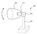
本発明の自立電源装置200に搭載されている太陽電池110は、波長800nmで発電効率が最大になるものを用いている。波長800nmは白色蛍光灯510が発するスペクトラム中でも強いものである。従って、白色蛍光灯510を光源とした光充電装置500を開発し、本発明の自立電源装置の充電器とした。次にこの充電装置について説明する。
As the
先ず、光源に使う白色蛍光灯510は持ち運びを考えて小さいのも、例えば20ワット以下のものが好ましい。本実施例に於いては、光強度を考えて20ワットの白色蛍光灯510を使用した。白色蛍光管の構造は通常の直管ではなく、曲管を用いて一見、白色電球の様な形状のものを用いた。次に集光し、光に指向性を持たせる為にパラボラ形状の金属板520を白色蛍光管510の後ろに配し、その後ろを蝶番530で固定し、パラボラ型金属板520と白色蛍光管510が縦に首を振れるようにした。蝶番530の下は支柱540とし、下部に錘を組み込み安定させた。
First, the
光充電器500は構造が非常に簡単であるが上、製作費が安いのが特徴である。使用方法に付いては、光充電器500を机などの上に置き、充電したい無線センサーネットワーク装置100の太陽電池面に向けて光りを照射するだけである。本実施例での充電実験において、約40分で充電が完了した。
The
本発明の実時間校正方法は保守不要の無線センサーネットワークを構築する上では有用な方法として利用価値があり、ネットワークに接続されているが、外から時間情報を得る事ができない特立した装置等の実時間校正に利用が可能と考える。 The real-time calibration method of the present invention has utility value as a useful method for constructing a maintenance-free wireless sensor network, and is a special device that is connected to the network but cannot obtain time information from the outside. It can be used for real-time calibration.
100 無線センサーネットワーク装置
110 太陽電池
120 センサー部
130 通信状態表示部
140 可動台
210 電気二重層キャパシタ
220 電圧検知器
230 実時間時計
240 電圧制御器
250 負荷部
260 電源スイッチ
270 ミニロジック回路
280 逆電防止ダイオード
410 蛍光灯
420 装置の置き台
500 光充電器
510 白色蛍光灯
520 パラボラ型金属板
530 蝶番
DESCRIPTION OF
Claims (4)
前記太陽電池で発電された電荷を蓄積する電気二重層キャパシタと、
前記太陽電池が発電できなくなった時に前記電気二重層キャパシタからの逆流電流を防止する逆電防止ダイオードと、
前記電気二重層キャパシタの充電状態を電圧値で確認する電圧検知器と、
間欠動作を時間で制御する実時間時計と、
前記電圧検知器と前記実時間時計からの論理和により電源供給を制御する電源スイッチと、
負荷部への電圧を制御する電圧制御器とからなる自立電源装置。 Solar cells,
An electric double layer capacitor for storing electric charges generated by the solar cell;
A reverse current prevention diode for preventing a reverse current from the electric double layer capacitor when the solar cell cannot generate electricity;
A voltage detector for confirming a charge state of the electric double layer capacitor by a voltage value;
A real-time clock that controls intermittent operation by time;
A power switch for controlling power supply by a logical sum from the voltage detector and the real time clock;
A self-supporting power supply device comprising a voltage controller for controlling the voltage to the load section.
Priority Applications (1)
| Application Number | Priority Date | Filing Date | Title |
|---|---|---|---|
| JP2005375102A JP2007181278A (en) | 2005-12-27 | 2005-12-27 | Autonomous power supply and wireless sensor network apparatus |
Applications Claiming Priority (1)
| Application Number | Priority Date | Filing Date | Title |
|---|---|---|---|
| JP2005375102A JP2007181278A (en) | 2005-12-27 | 2005-12-27 | Autonomous power supply and wireless sensor network apparatus |
Publications (1)
| Publication Number | Publication Date |
|---|---|
| JP2007181278A true JP2007181278A (en) | 2007-07-12 |
Family
ID=38305866
Family Applications (1)
| Application Number | Title | Priority Date | Filing Date |
|---|---|---|---|
| JP2005375102A Withdrawn JP2007181278A (en) | 2005-12-27 | 2005-12-27 | Autonomous power supply and wireless sensor network apparatus |
Country Status (1)
| Country | Link |
|---|---|
| JP (1) | JP2007181278A (en) |
Cited By (16)
| Publication number | Priority date | Publication date | Assignee | Title |
|---|---|---|---|---|
| WO2010120560A1 (en) * | 2009-03-31 | 2010-10-21 | Battelle Memorial Institute | Supercapacitor materials and devices |
| CN101951033A (en) * | 2010-08-24 | 2011-01-19 | 中国农业大学 | Device and method for intelligently supplying power to node based on wireless sensor network |
| CN102355067A (en) * | 2011-07-04 | 2012-02-15 | 东南大学 | Mobile wireless charging and power-supplying method of wireless sensor network node |
| CN102709962A (en) * | 2012-05-09 | 2012-10-03 | 东南大学 | Sensor network long-distance charging and power supplying system based on laser light source |
| US8471525B2 (en) | 2009-12-17 | 2013-06-25 | Electronics And Telecommunications Research Institute | Apparatus and method for charging internal battery in wireless sensor network |
| CN103219779A (en) * | 2013-05-13 | 2013-07-24 | 东南大学 | Wireless charging method for sensing network node |
| AT512413B1 (en) * | 2012-03-19 | 2013-08-15 | Michael Moser | Integrated flexible ice detector |
| JP2014042404A (en) * | 2012-08-22 | 2014-03-06 | Sharp Corp | Charging device, solar system, electrical system, and vehicle |
| JP5668132B1 (en) * | 2013-12-27 | 2015-02-12 | 株式会社フジクラ | Power storage system and power storage method |
| WO2015045687A1 (en) * | 2013-09-24 | 2015-04-02 | 株式会社村田製作所 | Power supply device, device incorporating this power supply device, and environmental energy evaluation device |
| CN107577189A (en) * | 2017-10-20 | 2018-01-12 | 中国电建集团成都勘测设计研究院有限公司 | A kind of accurate timing Rouser of automatic monitoring system |
| EP3327890A1 (en) | 2016-11-25 | 2018-05-30 | ABLIC Inc. | Power source device |
| WO2021045236A1 (en) | 2019-09-08 | 2021-03-11 | トライポッド・デザイン株式会社 | System and device |
| WO2021250970A1 (en) | 2020-06-12 | 2021-12-16 | トライポッド・デザイン株式会社 | Sensor |
| WO2022034887A1 (en) | 2020-08-11 | 2022-02-17 | トライポッド・デザイン株式会社 | Sensor system, sensor device, and sensing method |
| US11359940B2 (en) | 2018-02-28 | 2022-06-14 | Asahi Kasei Microdevices Corporation | Sensor apparatus and sensor system |
-
2005
- 2005-12-27 JP JP2005375102A patent/JP2007181278A/en not_active Withdrawn
Cited By (28)
| Publication number | Priority date | Publication date | Assignee | Title |
|---|---|---|---|---|
| US9007742B2 (en) | 2009-03-31 | 2015-04-14 | Battelle Memorial Institute | Supercapacitor materials and devices |
| WO2010120560A1 (en) * | 2009-03-31 | 2010-10-21 | Battelle Memorial Institute | Supercapacitor materials and devices |
| US8471525B2 (en) | 2009-12-17 | 2013-06-25 | Electronics And Telecommunications Research Institute | Apparatus and method for charging internal battery in wireless sensor network |
| CN101951033A (en) * | 2010-08-24 | 2011-01-19 | 中国农业大学 | Device and method for intelligently supplying power to node based on wireless sensor network |
| CN102355067A (en) * | 2011-07-04 | 2012-02-15 | 东南大学 | Mobile wireless charging and power-supplying method of wireless sensor network node |
| US9909568B2 (en) | 2012-03-19 | 2018-03-06 | Eologix Sensor Technology Gmbh | Device for detecting critical states of a surface |
| AT512413B1 (en) * | 2012-03-19 | 2013-08-15 | Michael Moser | Integrated flexible ice detector |
| AT512413A4 (en) * | 2012-03-19 | 2013-08-15 | Michael Moser | Integrated flexible ice detector |
| CN102709962A (en) * | 2012-05-09 | 2012-10-03 | 东南大学 | Sensor network long-distance charging and power supplying system based on laser light source |
| JP2014042404A (en) * | 2012-08-22 | 2014-03-06 | Sharp Corp | Charging device, solar system, electrical system, and vehicle |
| CN103219779A (en) * | 2013-05-13 | 2013-07-24 | 东南大学 | Wireless charging method for sensing network node |
| WO2015045687A1 (en) * | 2013-09-24 | 2015-04-02 | 株式会社村田製作所 | Power supply device, device incorporating this power supply device, and environmental energy evaluation device |
| JP5668132B1 (en) * | 2013-12-27 | 2015-02-12 | 株式会社フジクラ | Power storage system and power storage method |
| US10181748B2 (en) | 2013-12-27 | 2019-01-15 | Fujikura Ltd. | Power storage system and power storage method |
| EP3327890A1 (en) | 2016-11-25 | 2018-05-30 | ABLIC Inc. | Power source device |
| JP2018085888A (en) * | 2016-11-25 | 2018-05-31 | エイブリック株式会社 | Power supply device |
| US10075068B2 (en) | 2016-11-25 | 2018-09-11 | Ablic Inc. | Power source device |
| US10447155B2 (en) | 2016-11-25 | 2019-10-15 | Ablic Inc. | Power source device |
| TWI748000B (en) * | 2016-11-25 | 2021-12-01 | 日商艾普凌科有限公司 | Power source device |
| CN107577189A (en) * | 2017-10-20 | 2018-01-12 | 中国电建集团成都勘测设计研究院有限公司 | A kind of accurate timing Rouser of automatic monitoring system |
| CN107577189B (en) * | 2017-10-20 | 2023-12-19 | 中国电建集团成都勘测设计研究院有限公司 | Accurate timing wake-up method of automatic monitoring system |
| US11359940B2 (en) | 2018-02-28 | 2022-06-14 | Asahi Kasei Microdevices Corporation | Sensor apparatus and sensor system |
| KR20220062004A (en) | 2019-09-08 | 2022-05-13 | 토라이폿도 데자인 가부시키가이샤 | systems and devices |
| WO2021045236A1 (en) | 2019-09-08 | 2021-03-11 | トライポッド・デザイン株式会社 | System and device |
| WO2021250970A1 (en) | 2020-06-12 | 2021-12-16 | トライポッド・デザイン株式会社 | Sensor |
| KR20230023728A (en) | 2020-06-12 | 2023-02-17 | 토라이폿도 데자인 가부시키가이샤 | sensor |
| WO2022034887A1 (en) | 2020-08-11 | 2022-02-17 | トライポッド・デザイン株式会社 | Sensor system, sensor device, and sensing method |
| KR20230048374A (en) | 2020-08-11 | 2023-04-11 | 토라이폿도 데자인 가부시키가이샤 | Sensor system, sensor device and sensing method |
Similar Documents
| Publication | Publication Date | Title |
|---|---|---|
| JP2007181278A (en) | Autonomous power supply and wireless sensor network apparatus | |
| US8358099B2 (en) | Modular electric power system with a renewable energy power generating apparatus | |
| CN202125863U (en) | Intelligent LED lighting system and charging system for corresponding battery | |
| JP2016508665A (en) | Street light | |
| KR20120093697A (en) | Solar cell street lamp | |
| Aung et al. | Design of stand-alone solar street lighting system with LED | |
| JP5079617B2 (en) | Solar power generator | |
| US20090098832A1 (en) | Mobile device powered by alternative energy | |
| JP3195999U (en) | Mobile assembly type power supply and its use | |
| US20110176393A1 (en) | Battery-less environmental friendly quartz timepieces | |
| WO2009131622A2 (en) | Solar-powered valance-mounted lighting system | |
| Soh et al. | Building of a portable solar ac & dc power supply | |
| KR20110105922A (en) | Window type power generator using solar cell | |
| KR101557847B1 (en) | Small photovoltaic system for home | |
| KR200357241Y1 (en) | Traveling solar power plant | |
| KR102381357B1 (en) | Emotion lighting using indoor lighting power | |
| JP2015522235A (en) | AC solar panel system | |
| JP2008017631A (en) | Power saving apparatus | |
| US6660929B2 (en) | Electrical power module and system | |
| JP2005129800A (en) | Power generation system | |
| Mukherjee et al. | Maximum Utilisation of Solar Energy for Smart Home Lighting System | |
| CN101572419A (en) | Method and device utilizing solar energy to provide power supply for lighting lamps or other electrical appliances | |
| KR20130071315A (en) | Light device using solar enenrgy | |
| Amogpai | LED lighting combined with solar panels in developing countries | |
| Kauer et al. | High‐efficiency indoor photovoltaic energy harvesting |
Legal Events
| Date | Code | Title | Description |
|---|---|---|---|
| A621 | Written request for application examination |
Free format text: JAPANESE INTERMEDIATE CODE: A621 Effective date: 20080708 |
|
| A977 | Report on retrieval |
Free format text: JAPANESE INTERMEDIATE CODE: A971007 Effective date: 20090507 |
|
| A131 | Notification of reasons for refusal |
Free format text: JAPANESE INTERMEDIATE CODE: A131 Effective date: 20090602 |
|
| A761 | Written withdrawal of application |
Free format text: JAPANESE INTERMEDIATE CODE: A761 Effective date: 20090714 |