JP2007175399A - X-ray ct apparatus and its control method - Google Patents
X-ray ct apparatus and its control method Download PDFInfo
- Publication number
- JP2007175399A JP2007175399A JP2005379708A JP2005379708A JP2007175399A JP 2007175399 A JP2007175399 A JP 2007175399A JP 2005379708 A JP2005379708 A JP 2005379708A JP 2005379708 A JP2005379708 A JP 2005379708A JP 2007175399 A JP2007175399 A JP 2007175399A
- Authority
- JP
- Japan
- Prior art keywords
- subject
- scan
- ray
- interest
- value
- Prior art date
- Legal status (The legal status is an assumption and is not a legal conclusion. Google has not performed a legal analysis and makes no representation as to the accuracy of the status listed.)
- Granted
Links
- 238000000034 method Methods 0.000 title claims abstract description 32
- 239000002872 contrast media Substances 0.000 claims abstract description 28
- 238000002347 injection Methods 0.000 claims abstract description 20
- 239000007924 injection Substances 0.000 claims abstract description 20
- 238000003384 imaging method Methods 0.000 claims description 44
- 239000003795 chemical substances by application Substances 0.000 claims description 8
- 238000012360 testing method Methods 0.000 abstract description 14
- 239000000243 solution Substances 0.000 abstract 1
- 210000004204 blood vessel Anatomy 0.000 description 17
- 238000012545 processing Methods 0.000 description 12
- 230000002123 temporal effect Effects 0.000 description 9
- 238000013480 data collection Methods 0.000 description 5
- 210000000709 aorta Anatomy 0.000 description 4
- 238000001514 detection method Methods 0.000 description 4
- 238000010586 diagram Methods 0.000 description 4
- 238000013170 computed tomography imaging Methods 0.000 description 3
- 238000012937 correction Methods 0.000 description 3
- 238000012544 monitoring process Methods 0.000 description 3
- 206010002329 Aneurysm Diseases 0.000 description 2
- 210000002376 aorta thoracic Anatomy 0.000 description 2
- 210000000056 organ Anatomy 0.000 description 2
- 230000007704 transition Effects 0.000 description 2
- 210000003462 vein Anatomy 0.000 description 2
- 206010028980 Neoplasm Diseases 0.000 description 1
- 238000002583 angiography Methods 0.000 description 1
- 210000000702 aorta abdominal Anatomy 0.000 description 1
- 210000001367 artery Anatomy 0.000 description 1
- 239000008280 blood Substances 0.000 description 1
- 210000004369 blood Anatomy 0.000 description 1
- 230000036772 blood pressure Effects 0.000 description 1
- 238000012790 confirmation Methods 0.000 description 1
- 230000007423 decrease Effects 0.000 description 1
- 238000010790 dilution Methods 0.000 description 1
- 239000012895 dilution Substances 0.000 description 1
- 239000006185 dispersion Substances 0.000 description 1
- 238000000605 extraction Methods 0.000 description 1
- 238000005259 measurement Methods 0.000 description 1
- 238000007781 pre-processing Methods 0.000 description 1
- 230000035945 sensitivity Effects 0.000 description 1
- 210000001835 viscera Anatomy 0.000 description 1
Images


Classifications
-
- A—HUMAN NECESSITIES
- A61—MEDICAL OR VETERINARY SCIENCE; HYGIENE
- A61B—DIAGNOSIS; SURGERY; IDENTIFICATION
- A61B6/00—Apparatus or devices for radiation diagnosis; Apparatus or devices for radiation diagnosis combined with radiation therapy equipment
- A61B6/02—Arrangements for diagnosis sequentially in different planes; Stereoscopic radiation diagnosis
- A61B6/027—Arrangements for diagnosis sequentially in different planes; Stereoscopic radiation diagnosis characterised by the use of a particular data acquisition trajectory, e.g. helical or spiral
Landscapes
- Apparatus For Radiation Diagnosis (AREA)
Abstract
Description
本発明はX線CT装置及びその制御方法に関し、更に詳しくは、X線ファンビームにより被検体のスキャン読取を行う走査ガントリ部と、被検体を搭載する撮影テーブルと、上記各部の制御を行うとともに、走査ガントリ部で読み取ったスキャンデータに基づき被検体のCT断層像を再構成する制御部とを備えるX線CT装置の制御方法に関する。 The present invention relates to an X-ray CT apparatus and a control method thereof. More specifically, the present invention controls a scanning gantry unit that scans and scans a subject with an X-ray fan beam, an imaging table that mounts the subject, and the above-described units. The present invention relates to a control method for an X-ray CT apparatus including a control unit that reconstructs a CT tomographic image of a subject based on scan data read by a scanning gantry unit.
血管造影によるCT検査は腫瘍や動脈瘤等の状態を周囲の組織から際立たせて診断する目的で良く行われる。このような造影検査を適切に行うには造影剤が関心部位に丁度到達するタイミングに撮影を行う必要があるが、造影剤の進行速度には個人差(心拍数,血圧等)のみならず関心部位(血管の太さ)の相違によっても差があるため、従来は、予め造影剤を試験的に注入するとともに、関心部位におけるCT値の時間変化を観測することで、造影剤の到達時間を測定する所謂テストインジェクションが行われていた。 An angiographic CT examination is often performed for the purpose of diagnosing a tumor, aneurysm, or the like from a surrounding tissue. In order to properly perform such a contrast examination, it is necessary to perform imaging at the timing when the contrast medium reaches the region of interest, but the progress of the contrast medium is not only of individual differences (heart rate, blood pressure, etc.) but also of interest. Since there is also a difference depending on the difference in the region (blood vessel thickness), conventionally, the contrast agent arrival time is determined by injecting a contrast agent in advance on a trial basis and observing the temporal change in the CT value at the region of interest. A so-called test injection for measuring was performed.
しかし、従来は1度のテストインジェクションで1箇所しか測定できないため、複数箇所の測定を1回で能率良く行えなかった。 However, conventionally, since only one place can be measured by one test injection, the measurement at a plurality of places cannot be performed efficiently at one time.
この点、従来は、造影剤注入により時間変化する断層像中のCT値が所定のしきい値内となるように撮影速度(天板の移動速度及び又はガントリ回転速度)を実時間で制御しつつ、体軸方向に沿って複数の関心部位を連続的に造影検査可能なX線CT装置が知られている(特許文献1)。
しかし、断層像中のCT値をリアルタイムでしきい値判定する方式であると、実際に検出される造影剤のCT値は関心領域(ROI:Region of Interest)の部位(大動脈,動脈,臓器等)や形状(血管の太さ等)によっても異なってくるため、しきい値にもかなりの幅を持たせておく必要があり、このため、必ずしも最適CT値のタイミングに本番撮影が行えるとは限らない。また、関心領域のCT値が所定以上になるのを待って本番撮影を行う方式であると、造影剤の速度が遅い部位では待ち時間に無駄な被曝を与えることになる場合も少なくなく、低被曝の診断が行えない。 However, if the CT value in the tomographic image is determined in real time, the CT value of the contrast agent that is actually detected is the region of interest (ROI: Region of Interest) (aorta, artery, organ, etc.). ) And shape (thickness of the blood vessel, etc.), it is necessary to allow the threshold value to have a considerable width. For this reason, it is not always possible to perform actual imaging at the timing of the optimal CT value. Not exclusively. In addition, if the method of performing the actual imaging after waiting for the CT value of the region of interest to become a predetermined value or more, there is often a case where unnecessary exposure is given to the waiting time in a region where the speed of the contrast agent is low. Cannot diagnose exposure.
本発明は上記従来技術の問題点に鑑みなされたもので、その目的とする所は、テストインジェクションを低被曝で能率良く行えるX線CT装置及びその制御方法を提供することにある。 The present invention has been made in view of the above-described problems of the prior art, and an object of the present invention is to provide an X-ray CT apparatus capable of performing test injection efficiently with low exposure and a control method thereof.
上記の課題は例えば図5の構成により解決される。即ち、本発明(1)のX線CT装置の制御方法は、X線ファンビームにより被検体のスキャン読取を行う走査ガントリ部と、被検体を搭載する撮影テーブルと、上記各部の制御を行うとともに、走査ガントリ部で読み取ったスキャンデータに基づき被検体のCT断層像を再構成する制御部とを備えるX線CT装置の制御方法であって、前記制御部は、被検体に血管造影剤が注入されてから所定時間の経過後、該被検体の体軸方向における複数の関心部位S2,S3,S4を含む領域に対してヘリカルシャトルスキャン読取を行うスキャン読取ステップと、前記読み取ったスキャンデータに基づき各関心部位S2,S3,S4のCT断層像を再構成するとともに
、得られた各CT値に基づき各関心部位におけるCT値の時間変化を求めるCT値時間変化演算ステップとを実行するものである。
The above problem is solved by the configuration of FIG. That is, the control method of the X-ray CT apparatus of the present invention (1) controls the scanning gantry unit that scans and scans the subject with the X-ray fan beam, the imaging table on which the subject is mounted, and the above-described units. And a control unit for reconstructing a CT tomogram of a subject based on scan data read by a scanning gantry unit, wherein the control unit injects an angiographic contrast agent into the subject. A scan reading step of performing helical shuttle scan reading on a region including a plurality of regions of interest S2, S3, S4 in the body axis direction of the subject after elapse of a predetermined time, and based on the read scan data CT values for reconstructing CT tomographic images of the regions of interest S2, S3, and S4, and for obtaining temporal changes in the CT values at the regions of interest based on the obtained CT values And it executes the between change computing step.
本発明(1)では、体軸方向における複数の関心部位S2,S3,S4を含む領域をヘリカルシャトルスキャンにより複数回撮影する構成により、各関心部位におけるCT値の時間変化を少ない被曝で効率良く検出できる。また、各関心部位におけるCT値の時間変化に基づいて、後に各関心部位を本番で造影撮影する際の各最適の読取開始時間を容易かつ正確に設定できる。 In the present invention (1), the region including the plurality of regions of interest S2, S3, and S4 in the body axis direction is imaged a plurality of times by the helical shuttle scan, and the time change of the CT value at each region of interest is efficiently performed with little exposure. It can be detected. In addition, based on the time change of the CT value at each region of interest, it is possible to easily and accurately set each optimum reading start time when each region of interest is imaged in real time.
なお、上記ヘリカルシャトルスキャンとは、被検体をヘリカルスキャンしながら、該被検体とX線ファンビームとの相対位置関係を体軸方向に往復動させるスキャンを言う。この往復動には、走査ガントリを固定して撮影テーブルが往復動する場合と、撮影テーブルを固定して走査ガントリが往復動する場合とが含まれる。 The helical shuttle scan refers to a scan that reciprocally moves the relative positional relationship between the subject and the X-ray fan beam in the body axis direction while helically scanning the subject. This reciprocation includes a case where the scanning gantry is fixed and the imaging table is reciprocated and a case where the imaging table is fixed and the scanning gantry is reciprocated.
また上記の課題は例えば図6の構成により解決される。即ち、本発明(2)のX線CT装置の制御方法は、X線ファンビームにより被検体のスキャン読取を行う走査ガントリ部と、被検体を搭載する撮影テーブルと、上記各部の制御を行うとともに、走査ガントリ部で読み取ったスキャンデータに基づき被検体のCT断層像を再構成する制御部とを備えるX線CT装置の制御方法であって、前記制御部は、被検体に血管造影剤が注入されてから所定時間の経過後、該被検体の体軸方向における複数の関心部位S2,S4を含む領域に対してヘリカルシャトルスキャンを行うと供に、各関心部位S2,S4に対するスキャン読取に際してのみX線曝射を行うスキャン読取ステップと、前記読み取ったスキャンデータに基づき各関心部位S2,S4のCT断層像を再構成するとともに、得られた各CT値に基づき各関心部位におけるCT値の時間変化を求めるCT値時間変化演算ステップとを実行するものである。 Further, the above problem is solved by, for example, the configuration of FIG. In other words, the control method of the X-ray CT apparatus of the present invention (2) controls the scanning gantry unit that scans and scans the subject with the X-ray fan beam, the imaging table on which the subject is mounted, and the above-described units. And a control unit for reconstructing a CT tomogram of a subject based on scan data read by a scanning gantry unit, wherein the control unit injects an angiographic contrast agent into the subject. After a predetermined time has elapsed, a helical shuttle scan is performed on a region including a plurality of regions of interest S2 and S4 in the body axis direction of the subject, and only when scanning the regions of interest S2 and S4. A scan reading step for performing X-ray exposure, and CT tomograms of the regions of interest S2 and S4 are reconstructed based on the read scan data, and each obtained CT And executes the CT value time variation calculation step of obtaining a time change in CT value of each region of interest based on.
本発明(2)では、被検体の複数の関心部位S2,S4を含む領域に対してヘリカルシャトルスキャンを行うと供に、各関心部位S2,S4に対するスキャン読取に際してのみX線曝射を行うので、被検体の被曝を一層低減できる。 In the present invention (2), since the helical shuttle scan is performed on the region including the plurality of regions of interest S2 and S4 of the subject, the X-ray exposure is performed only when scanning the regions of interest S2 and S4. The exposure of the subject can be further reduced.
また上記の課題は例えば図7の構成により解決される。即ち、本発明(3)のX線CT装置の制御方法は、X線ファンビームにより被検体のスキャン読取を行う走査ガントリ部と、被検体を搭載する撮影テーブルと、上記各部の制御を行うとともに、走査ガントリ部で読み取ったスキャンデータに基づき被検体のCT断層像を再構成する制御部とを備えるX線CT装置の制御方法であって、前記制御部は、血管造影剤が注入されてから所定時間の経過後、該被検体の体軸方向における複数の関心部位S2,S3,S4を含む複数の領域に対して予め定められたスキャンシーケンスに従い順次にヘリカルシャトルスキャン読取を行うスキャン読取ステップと、前記読み取ったスキャンデータに基づき各関心部位S2,S3,S4のCT断層像を再構成するとともに、得られた各CT値に基づき各関心部位におけるCT値の時間変化を求めるCT値時間変化演算ステップとを実行するものである。 The above problem is solved by the configuration of FIG. 7, for example. That is, the X-ray CT apparatus control method of the present invention (3) controls the scanning gantry unit that scans and scans the subject with the X-ray fan beam, the imaging table on which the subject is mounted, and the above-described units. , A control method for an X-ray CT apparatus comprising a control unit for reconstructing a CT tomogram of a subject based on scan data read by a scanning gantry unit, wherein the control unit is configured to inject an angiographic agent. A scan reading step of sequentially performing helical shuttle scan reading according to a predetermined scan sequence for a plurality of regions including a plurality of regions of interest S2, S3, S4 in the body axis direction of the subject after elapse of a predetermined time; Based on the read scan data, a CT tomogram of each region of interest S2, S3, S4 is reconstructed, and each interest is based on the obtained CT values. And executes the CT value time variation calculation step of obtaining a time change of the CT values in the position.
本発明(3)では、複数の関心領域に対して順次ヘリカルシャトルスキャン読取を行うことにより、複数部位をそれぞれに高い繰り返し密度で効率よくスキャンできる。従って、より高い精度(密度)でCT値のピークを検出でき、これに基づき各関心部位に対して最適の読取開始時間を設定できる。 In the present invention (3), by sequentially performing helical shuttle scan reading on a plurality of regions of interest, it is possible to efficiently scan a plurality of parts with a high repetition density. Accordingly, the peak of the CT value can be detected with higher accuracy (density), and the optimum reading start time can be set for each region of interest based on this.
なお、予め定められたスキャンシーケンスとは、各関心部位に対してそれぞれにヘリカルシャトルスキャンを十分に行えるように予め大まかに見積もられたスキャンシーケンス(スキャン速度、各部位毎のシャトル繰り返し回数等)である。 The predetermined scan sequence is a scan sequence roughly estimated in advance so that a helical shuttle scan can be sufficiently performed for each region of interest (scan speed, number of shuttle repetitions for each region, etc.) It is.
本発明(4)では、上記本発明(1)〜(3)において、前記求めた各CT値の時間変化に基づいて前記造影剤注入から各関心部位におけるCT値のピークが得られるまでの各遅延時間を求める遅延時間演算ステップを更に実行するものである。 In the present invention (4), in each of the present inventions (1) to (3), the CT value peak at each region of interest is obtained from the contrast agent injection based on the time change of each obtained CT value. The delay time calculating step for obtaining the delay time is further executed.
本発明(4)によれば、各関心部位におけるCT値の時間変化(カーブ)を分析(ピークを検出等)することで、該各ピークに対応する遅延時間に基づき、後に各関心部位を本番で造影撮影する際の最適の各読取開始時間(及び、場合によっては読取終了時間)を容易かつ正確に設定できる。 According to the present invention (4), by analyzing the temporal change (curve) of the CT value at each region of interest (detecting a peak or the like), each region of interest is subsequently produced based on the delay time corresponding to each peak. The optimum reading start time (and reading end time in some cases) when performing contrast imaging can be set easily and accurately.
また本発明(5)のX線CT装置は、X線ファンビームにより被検体のスキャン読取を行う走査ガントリ部と、被検体を搭載する撮影テーブルと、上記各部の制御を行うとともに、走査ガントリ部で読み取ったスキャンデータに基づき被検体のCT断層像を再構成する制御部とを備えるX線CT装置であって、前記制御部は、被検体に血管造影剤が注入されてから所定時間の経過後、該被検体の体軸方向における複数の関心部位を含む領域に対してヘリカルシャトルスキャン読取を行うスキャン読取手段と、前記読み取ったスキャンデータに基づき各関心部位のCT断層像を再構成するとともに、得られた各CT値に基づき各関心部位におけるCT値の時間変化を求めるCT値時間変化演算手段とを備えるものである。
In addition, the X-ray CT apparatus of the present invention (5) controls the scanning gantry unit that scans and scans the subject with the X-ray fan beam, the imaging table on which the subject is mounted, and the above-described units, and the scanning gantry unit. An X-ray CT apparatus comprising a control unit for reconstructing a CT tomographic image of a subject based on the scan data read in
また本発明(6)のX線CT装置は、X線ファンビームにより被検体のスキャン読取を行う走査ガントリ部と、被検体を搭載する撮影テーブルと、上記各部の制御を行うとともに、走査ガントリ部で読み取ったスキャンデータに基づき被検体のCT断層像を再構成する制御部とを備えるX線CT装置であって、前記制御部は、被検体に血管造影剤が注入されてから所定時間の経過後、該被検体の体軸方向における複数の関心部位を含む領域に対してヘリカルシャトルスキャンを行うと供に、各関心部位に対するスキャン読取に際してのみX線曝射を行うスキャン読取手段と、前記読み取ったスキャンデータに基づき各関心部位のCT断層像を再構成するとともに、得られた各CT値に基づき各関心部位におけるCT値の時間変化を求めるCT値時間変化演算手段とを備えるものである。
In addition, the X-ray CT apparatus of the present invention (6) controls the scanning gantry unit that scans and scans the subject with the X-ray fan beam, the imaging table on which the subject is mounted, and the above-described units, and the scanning gantry unit. An X-ray CT apparatus comprising a control unit for reconstructing a CT tomographic image of a subject based on the scan data read in
本発明(7)では、上記本発明(6)において、スキャン読取手段は、X線曝射を行わない区間における体軸方向のスキャンピッチ(速度)を通常よりも速くするものである。従って、被検体の被曝をより低減できるとともに、各関心部位のスキャンをより高い繰り返し密度で行える為、CT値のピークタイミングをより高精度で検出できる。 In the present invention (7), in the present invention (6), the scan reading means makes the scan pitch (velocity) in the body axis direction faster than usual in the section where X-ray exposure is not performed. Accordingly, the exposure of the subject can be further reduced, and each region of interest can be scanned at a higher repetition density, so that the peak timing of the CT value can be detected with higher accuracy.
また本発明(8)のX線CT装置は、X線ファンビームにより被検体のスキャン読取を行う走査ガントリ部と、被検体を搭載する撮影テーブルと、上記各部の制御を行うとともに、走査ガントリ部で読み取ったスキャンデータに基づき被検体のCT断層像を再構成する制御部とを備えるX線CT装置であって、前記制御部は、血管造影剤が注入されてから所定時間の経過後、該被検体の体軸方向における複数の関心部位を含む複数の領域に対して予め定められたスキャンシーケンスに従い順次にヘリカルシャトルスキャン読取を行うスキャン読取手段と、前記読み取ったスキャンデータに基づき各関心部位のCT断層像を再構成するとともに、得られた各CT値に基づき各関心部位におけるCT値の時間変化を求めるCT値時間変化演算手段とを備えるものである。 In addition, the X-ray CT apparatus of the present invention (8) controls a scanning gantry unit that scans and scans a subject with an X-ray fan beam, an imaging table on which the subject is mounted, and the above-described units, and a scanning gantry unit. An X-ray CT apparatus comprising a control unit for reconstructing a CT tomographic image of a subject based on the scan data read in step (i), wherein the control unit is configured to pass the predetermined time after the angiographic agent is injected. Scan reading means for sequentially reading a helical shuttle scan in accordance with a predetermined scan sequence for a plurality of regions including a plurality of regions of interest in the body axis direction of the subject, and each region of interest based on the read scan data CT value time change calculation means for reconstructing a CT tomographic image and obtaining time change of the CT value at each region of interest based on the obtained CT values It is those with a.
本発明(9)では、上記本発明(5)〜(8)において、前記求めた各CT値の時間変化に基づいて前記造影剤注入から各関心部位におけるCT値のピークが得られるまでの各遅延時間を求める遅延時間演算手段を更に備えるものである。 In the present invention (9), in each of the present inventions (5) to (8), each of the steps from the injection of the contrast agent to the peak of the CT value at each site of interest is obtained based on the temporal change of the obtained CT values. The apparatus further includes a delay time calculating means for obtaining the delay time.
本発明(10)では、上記本発明(8)において、スキャン読取手段は、隣接する関心
部位のスキャン読取に遷移する際には少なくとも1往復以上に渡って該隣接する両関心部位を含む領域のヘリカルシャトルスキャン読取を行うものである。従って、各関心部位間の遷移部分におけるCT値の欠落が生じ難い。
In the present invention (10), in the above-mentioned present invention (8), when the scan reading means shifts to the scan reading of the adjacent region of interest, at least one round-trip of the region including both adjacent regions of interest is included. Helical shuttle scan reading is performed. Accordingly, it is difficult for the CT value to be lost in the transition portion between the regions of interest.
本発明(11)では、上記本発明(4)〜(10)において、撮影テーブルは被検体体軸方向に往復動可能であるとともに、スキャン読取手段は走査ガントリ部の開口部に対して撮影テーブルを往復動させることにより被検体のヘリカルシャトルスキャンを行うものである。 In the present invention (11), in the present inventions (4) to (10), the imaging table can reciprocate in the direction of the subject body axis, and the scan reading means is an imaging table with respect to the opening of the scanning gantry section. The subject is subjected to a helical shuttle scan by reciprocating.
本発明(12)では、上記本発明(4)〜(10)において、走査ガントリ部は被検体体軸方向に往復動可能であるとともに、スキャン読取手段は撮影テーブルに搭載された被検体に対して走査ガントリ部を往復動させることにより被検体のヘリカルシャトルスキャンを行うものである。アンギオCTシウテムでは、被検体をスキャンするに際して走査ガントリ部を移動させるものがあるが、本発明はこのようなシステムに適用して好適である。 In the present invention (12), in the above-mentioned present inventions (4) to (10), the scanning gantry section can reciprocate in the direction of the subject body axis, and the scan reading means can move the subject mounted on the imaging table. Thus, a helical shuttle scan of the subject is performed by reciprocating the scanning gantry. Some angio CT cymtems move the scanning gantry when scanning a subject, but the present invention is suitable for application to such a system.
以上述べた如く本発明によれば、テストインジェクションによる本番撮影の予測がより正確に行えるため、血管造影を伴うCT撮影の信頼性、安全性の改善に寄与するところが極めて大きい。 As described above, according to the present invention, since actual imaging can be predicted more accurately by test injection, it greatly contributes to improving the reliability and safety of CT imaging accompanied with angiography.
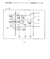
以下、添付図面に従って本発明に好適なる複数の実施の形態を詳細に説明する。なお、全図を通して同一符号は同一又は相当部分を示すものとする。図1は実施の形態によるX線CT装置の構成を示す図である。この装置は、X線ファンビームXLFBにより被検体100のスキャン読取を行う走査ガントリ部30と、被検体100を載せて体軸CLbの方向に移動させる撮影テーブル20と、上記各部30,20の遠隔制御を行うとともに、技師や医師等が操作をする操作コンソール部10とを備える。
Hereinafter, a plurality of preferred embodiments of the present invention will be described in detail with reference to the accompanying drawings. Note that the same reference numerals denote the same or corresponding parts throughout the drawings. FIG. 1 is a diagram showing a configuration of an X-ray CT apparatus according to an embodiment. This apparatus includes a
走査ガントリ部30において、31は回転陽極型のX線管、31AはX線制御部、32はX線スライス幅の制限を行うコリメータ、32Aはコリメータ制御部、33はチャネルCH方向に並ぶ多数(n=1000程度)のX線検出素子が体軸CLbの方向の複数列に配列されているマルチX線検出器、34はX線検出器33の検出信号に基づき被検体の投影データを生成し、収集するデータ収集部(DAS:Data Acquisition System)、35は上記X線撮影系を被検体体軸の回りに回転自在に支持するガントリ、35Aはガントリ35の回転制御部である。
In the
操作コンソール部10において、11はX線CT装置の主制御・処理(スキャン制御,CT断層像の再構成処理等)を行う中央処理装置、11aはそのCPU、11bはCPU11aが使用するRAM,ROM等からなる主メモリ(MM)、12はキーボードやマウス等を含む指令やデータの入力装置、13はスキャン計画情報やCT断層像等を表示するための表示装置(CRT)、14はCPU11aと走査ガントリ部30及び撮影テーブル20との間で各種制御信号CSやモニタ信号MS等のやり取りを行う制御インタフェース、15はデータ収集部34からの投影データを一時的に蓄積するデータ収集バッファ、16はデータ収集バッファ15からの投影データを蓄積・格納するとともに、X線CT装置の運用に必要な各種アプリケーション・プログラムや各種演算/補正用のデータファイル等を格納している二次記憶装置(ハードディスク装置等)である。
In the
次にこのX線CT装置による基本的な撮影動作を説明する。被検体100を走査ガントリ部30の空洞部内に位置させた状態で、X線管31からのX線ビームXLFBを被検体
100に照射する。この状態で、X線管31からのX線ファンビームXLFBは被検体100を透過してX線検出器33の各検出器列に一斉に入射する。データ収集部34はX線検出器33の各検出列出力に対応する投影データg(X,θ)を生成し、これらをデータ収集バッファ15に格納する。ここで、Xは検出器のチャネル番号、θは投影(ビュー)角を表す。更に、走査ガントリ35が僅かに回転した各ビュー角θで上記同様のX線投影を行い、こうして走査ガントリ1回転分の投影データを収集・蓄積する。また、同時にアキシャル/ヘリカルスキャン方式に従って撮影テーブル20を体軸CLbの方向に間欠的/連続的に移動させ、こうして被検体の所要撮影領域についての全投影データを収集・蓄積し、これらを二次記憶装置16に格納する。そして、CPU11aは、上記全スキャンの終了後、又はスキャンと並行して得られた投影データに基づき被検体100のCT断層像を再構成し、これを表示装置13に表示する。
Next, a basic imaging operation by this X-ray CT apparatus will be described. The subject 100 is irradiated with the X-ray beam XLFB from the
本実施の形態では、このようなX線CT装置を使用したテストインジェクションにより心臓を通過した造影剤が体軸方向の複数の関心部位に到達する各時間を一挙に効率よく求める場合を詳細に説明する。なお、この場合の撮影テーブル20は被検体100を搭載して体軸方向に移動可能な天板21を備え、該天板21は一定速度(場合によっては可変速度)でガントリ空洞部内を往復動可能である。
In the present embodiment, a detailed description will be given of a case in which the time when the contrast agent that has passed through the heart reaches a plurality of regions of interest in the body axis direction is efficiently obtained at once by test injection using such an X-ray CT apparatus. To do. In this case, the imaging table 20 includes a
図2は実施の形態によるX線CT撮影処理のフローチャートで、後述する幾つかのスキャン方法に共通な基本的処理を示している。好ましくは、事前に被検体100のスカウトスキャン(2次元レントゲン撮影に相当)を行った後、この処理に入る。ステップS11では続く被検体へのテストインジェクションに伴うヘリカルシャトルスキャンのためのスキャンパラメータを設定する。 FIG. 2 is a flowchart of X-ray CT imaging processing according to the embodiment, and shows basic processing common to several scanning methods described later. Preferably, after performing a scout scan (corresponding to two-dimensional X-ray imaging) of the subject 100 in advance, this process is entered. In step S11, scan parameters for a helical shuttle scan accompanying the subsequent test injection to the subject are set.
図3に一例のスキャンパラメータ設定画面を示す。事前のスカウトスキャンの終了後、表示部13には続くヘリカルシャトルスキャンのためのスキャン設定画面13Aが表示され、技師等は必要なスキャンパラメータをマウスでクリック入力又はキー入力等する。この例では腕の静脈に注入した血管造影剤が心臓から上行大動脈、下行大動脈、胸部大動脈を通って腹部大動脈に到達する過程が監視対象であり、一例のスキャンパラメータは以下の通りである。
FIG. 3 shows an example scan parameter setting screen. After the previous scout scan is completed, a
スキャンタイプ=ヘリカルシャトルスキャン
スキャン開始位置=Z1
スキャン反転位置=Z5
スキャンシーケンス=Z1,Z5間を120秒間に渡って単純に往復
被検体のスカウト像100に重ねてスキャン開始,反転位置Z1,Z5を表す直線が表示され、技師等は画面を見ることで、スキャン計画を確認し、又は変更可能である。
Scan type = helical shuttle scan Scan start position = Z1
Scan reversal position = Z5
Scan sequence = Z1 and Z5 are simply reciprocated over 120 seconds. The scan starts on the subject's
ステップS12では技師等がリコンパラメータの設定を行う。図3において、被検体体軸方向の複数の関心部位S2,S3,S4について各CT値の時間変化を求めるためのリコンパラメータの設定を行う。関心部位(この例では血管部)の断層像をリコンする各スライス位置S2,S3,S4は体軸方向の各スキャン位置Z2,Z3,Z4にそれぞれ対応している。ステップS13では確認「CONFIRM」ボタンの入力を待つ。 In step S12, an engineer or the like sets recon parameters. In FIG. 3, the recon parameters for determining the temporal change of each CT value are set for a plurality of regions of interest S2, S3, S4 in the direction of the subject body axis. Each slice position S2, S3, S4 that reconstitutes a tomographic image of a region of interest (in this example, a blood vessel portion) corresponds to each scan position Z2, Z3, Z4 in the body axis direction. In step S13, input of a confirmation “CONFIRM” button is awaited.
こうして、やがて、技師等は「CONFIRM」ボタンを入力可能と判断すると、被検体の腕の静脈に血管造影剤を注入し、「CONFIRM」ボタンを押す。これにより、処理は、好ましくは前記注入した造影剤が心臓を通過して上行大動脈に到達するに要する所定時間を待って後、ステップS14に進む。 Thus, when the engineer or the like eventually determines that the “CONFIRM” button can be input, an angiographic agent is injected into the vein of the arm of the subject and the “CONFIRM” button is pressed. Thereby, the processing preferably proceeds to step S14 after waiting for a predetermined time required for the injected contrast agent to pass through the heart and reach the ascending aorta.
ステップS14では上記図3のスキャン範囲をカバーする範囲についてヘリカルシャト
ルスキャンを行い、ステップS15ではその投影データを収集して、これらを最終的にハードディスク装置16に蓄積・格納する。一例のヘリカルシャトルスキャンは、被検体のヘリカルスキャンを行いつつ、該被検体(天板21)を一方向だけでなく、体軸の前後方向に往復動させるスキャンである。ここで、ヘリカルスキャンとは、ガントリ35を一定速度で回転させた状態で被検体を撮影しつつ、該被検体(天板21)を体軸方向に一定速度で連続的に移動させるスキャンを言う。
In step S14, a helical shuttle scan is performed for the range that covers the scan range of FIG. 3, and in step S15, the projection data is collected and finally stored and stored in the
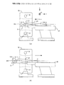
図4に一例のヘリカルシャトルスキャンの動作イメージを示す。図4(A)において、往路のヘリカルスキャンは、ガントリ35を一定速度で回転させた状態で被検体をZ1からZ5の範囲でヘリカルスキャンをすべく、天板21をZ1からZ2のスキャン位置に一定速度で連続的に搬送することで行われる。図4(B)において、復路のヘリカルスキャンは、同じくガントリ35を一定速度で回転させた状態で被検体をZ5からZ1の範囲でヘリカルスキャンをすべく、天板21をZ5からZ1のスキャン位置に一定速度で連続的に搬送することで行われる。以上の動作を所定回数分連続的に繰り返す(shuttle)ことでヘリカルシャトルスキャンを行う。
FIG. 4 shows an example of an operation image of the helical shuttle scan. In FIG. 4A, in the forward helical scan, the top 21 is moved to the scan position from Z1 to Z2 in order to perform a helical scan in the range from Z1 to Z5 with the
図2に戻り、ステップS16では所要のスキャンシーケンスを完了したか否かを判別し、完了でない場合はステップS14に戻る。こうして、やがて所要のスキャンシーケンスを終了すると、ステップS17に進み、ハードディスク装置16から各スライス面S2,S3,S4の画像再構成に必要な各投影データg(X,θ)を順に抽出する。まず、往路の各投影データを抽出し、次に復路の各投影データを抽出し、こうして、所要シャトル回数分の投影データを抽出する。
Returning to FIG. 2, in step S16, it is determined whether or not the required scan sequence is completed. If not, the process returns to step S14. Thus, when the required scan sequence is finished, the process proceeds to step S17, and each projection data g (X, θ) necessary for image reconstruction of each slice plane S2, S3, S4 is sequentially extracted from the
ステップS18では前記抽出した各投影データに対して所定の前処理(レファレンス補正処理、チャネル間感度補正処理等)を行う。ステップS19では各スライス面S2,S3,S4に各対応する画像再構成用データh(X,θ)を公知のデータ補間演算処理により生成し、ステップS20では各スライス面S2,S3,S4の関心部位(血管部等)のCT断層像を再構成する。ステップS21では血管部(造影剤)のCT値を時間軸に沿って求め、ステップS22では得られた各CT断層像と血管部(ROI)のCT値の時間変化とを画面に表示し、この処理を抜ける。 In step S18, predetermined preprocessing (reference correction processing, interchannel sensitivity correction processing, etc.) is performed on each extracted projection data. In step S19, image reconstruction data h (X, θ) corresponding to each slice plane S2, S3, S4 is generated by a known data interpolation calculation process, and in step S20, the interest of each slice plane S2, S3, S4 is generated. Reconstruct a CT tomogram of the site (blood vessel, etc.). In step S21, the CT value of the blood vessel part (contrast agent) is obtained along the time axis. In step S22, the obtained CT tomographic images and the temporal change of the CT value of the blood vessel part (ROI) are displayed on the screen. Exit processing.
なお、上記実施の形態では一連のヘリカルシャトルスキャンの完了後にステップS17以降の画像再構成処理を開始したが、これに限らない。ヘリカルシャトルスキャンの進行と並行して、必要な投影データの抽出及び再構成可能となったCT断層像の画像再構成を順次行い、得られたCT断層像と血管部のCT値とをその都度直ちに表示部13にリアルタイム表示(Auto View)しても良い。
In the above embodiment, the image reconstruction process after step S17 is started after completion of a series of helical shuttle scans. However, the present invention is not limited to this. In parallel with the progress of the helical shuttle scan, extraction of necessary projection data and reconstruction of CT tomograms that can be reconstructed are sequentially performed, and the obtained CT tomograms and CT values of the blood vessels are obtained each time. Immediately, real-time display (Auto View) may be performed on the
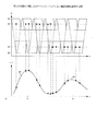
図5は第1の実施の形態によるテストインジェクション撮影処理を説明する図で、このヘリカルシャトルスキャンはガントリ35を一定速度で回転させた状態で天板21をスキャン範囲Z1〜Z5内で往復動させる単純な場合を示している。図には、各関心部位S2,S3,S4におけるCT値の時間変化を併せて示す。時刻t0で造影剤を注入後、該造影剤が心臓から流出する十分前に被検体のヘリカルシャトルスキャンを開始する。往路Z1〜Z5のヘリカルスキャンに2秒かかるとすると、復路Z5〜Z1のヘリカルスキャンにも2秒かかり、トータル4秒で1往復となる。これを繰り返すことでヘリカルシャトルスキャンを行う。
FIG. 5 is a diagram for explaining the test injection imaging process according to the first embodiment. In this helical shuttle scan, the top 21 is reciprocated within the scan ranges Z1 to Z5 with the
挿入図(a)に血管部断面の再構成イメージを示す。一般に、血液のCT値が30〜40程度であるのに対し、周囲の内臓のCT値は50前後であるため、このままでは血管部の再構成画像に十分なコントラストは得られないが、造影剤のCT値は200〜300程度であるため造影剤が充填されることにより血管部のCT値は時間経過とともに増加し、
血管部(動脈瘤等)の状態を明瞭に診断できるようになる。そして、やがて造影剤が通過するとCT値も次第に低下する。
Inset (a) shows a reconstructed image of the blood vessel section. In general, the CT value of blood is about 30 to 40, whereas the CT value of the surrounding internal organs is around 50, so that sufficient contrast cannot be obtained in the reconstructed image of the blood vessel part as it is. Since the CT value of the blood vessel is about 200 to 300, the CT value of the blood vessel increases as time passes by being filled with the contrast agent.
It becomes possible to clearly diagnose the state of a blood vessel (an aneurysm or the like). Then, the CT value gradually decreases as the contrast medium passes.
今、関心部位S2に着目すると、復路と往路のスキャンがスライス面S2を通過する度に関心部位S2の再構成画像が得られ、各時点における血管部のCT値が得られる。更に、各時点のCT値を黒点でプロットするとともに、各黒点間を滑らかな曲線で補間すると、図示の様に上に凸のカーブが得られる。そこで、該カーブのピーク点を求めると、血管部S2について造影剤注入開始時刻t0から最も造影剤に良く染まった関心部位S2の断層画像が得られるまでに遅延時間t1を要することが分かる。これにより、本番の造影検査に際しては、遅延時間t1を基準として、その前後にそれぞれ所定時間幅を有するような造影検査時間を設定することで、関心部位S2についての最適の造影検査を低被曝で効率よく行える。 Now, paying attention to the region of interest S2, a reconstructed image of the region of interest S2 is obtained each time the backward and forward scans pass through the slice plane S2, and the CT value of the blood vessel portion at each time point is obtained. Furthermore, when the CT values at each time point are plotted with black dots and interpolated between the black dots with a smooth curve, an upwardly convex curve is obtained as shown in the figure. Therefore, when the peak point of the curve is obtained, it can be seen that a delay time t1 is required from the contrast agent injection start time t0 to the tomographic image of the region of interest S2 that is most stained with the contrast agent for the blood vessel S2. Thus, in the actual contrast examination, the optimum contrast examination for the region of interest S2 can be performed at low exposure by setting the contrast examination time having a predetermined time width before and after the delay time t1 as a reference. It can be done efficiently.
以下、同様にして関心部位S3,S4に各対応する遅延時間t2,t3が高い精度で求まる。なお、各関心部位S2,S3のCT値につては造影剤の進行とともに分散・希釈化されることにより、次第に低くなる傾向にあり、また各遅延時間t1,t2,t3と各部の通過時間(ピーク形状の鈍さ)については、血管が次第に細くなることにより、次第に大きくかつ鈍くなる傾向にある。 Hereinafter, similarly, the delay times t2 and t3 corresponding to the regions of interest S3 and S4 are obtained with high accuracy. The CT values of the regions of interest S2 and S3 tend to gradually become lower due to dispersion / dilution with the progress of the contrast agent, and each delay time t1, t2, t3 and the passage time of each part ( With regard to the dullness of the peak shape, the blood vessels tend to become gradually smaller and larger and dull.
本第1の実施の形態によれば、比較的単純なヘリカルシャトルスキャンを用いたテストインジェクションにより体軸方向の複数関心部位における各CT値の時間変化が低被曝で効率よく求まる。従って、本番撮影ではそれぞれのピークを含む前後適切な時間幅を設定可能となり、これにより本番の造影検査を低被曝で効率よくかつ正確に行える。 According to the first embodiment, the time change of each CT value in a plurality of regions of interest in the body axis direction can be obtained efficiently with low exposure by test injection using a relatively simple helical shuttle scan. Accordingly, it is possible to set an appropriate time width before and after each peak in the actual imaging, thereby enabling the actual contrast examination to be performed efficiently and accurately with low exposure.
図6は第2の実施の形態によるテストインジェクション撮影処理を説明する図で、被検体の関心部位S2,S4の撮影時のみX線を曝射する場合を示している。天板21(被検体)の往復動については上記第1の実施の形態で述べたものと同様である。この例では血管部S2が関心部位から除外されているため、この区間におけるX線の曝射を行わないようにしている。図は、X線の曝射されるスキャン範囲を幅広の帯(塗りつぶし)で示し、X線が曝射されない部分を点線で示している。従って、被検体の被曝量を大幅に低減できる。 FIG. 6 is a diagram for explaining test injection imaging processing according to the second embodiment, and shows a case where X-rays are exposed only during imaging of the regions of interest S2 and S4 of the subject. The reciprocating motion of the top board 21 (subject) is the same as that described in the first embodiment. In this example, since the blood vessel portion S2 is excluded from the region of interest, X-ray exposure is not performed in this section. In the figure, the scanning range to which X-rays are exposed is indicated by a wide band (filled), and the portion where X-rays are not exposed is indicated by dotted lines. Therefore, the exposure dose of the subject can be greatly reduced.
なお、X線を曝射しない部分における天板21の搬送ピッチを通常よりも速く(シャトル可変ピッチヘリカル)することが可能であり、こうすれば、より一層の被曝低減が図れる。
In addition, it is possible to make the conveyance pitch of the
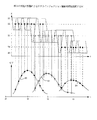
図7は第3の実施の形態によるテストインジェクション撮影処理を説明する図で、被検体の各関心部位S2,S3,S4の順に必要最小限のヘリカルシャトルスキャンを繰り返し行う場合を示している。図において、この場合の天板21は第1の関心部位S2を含む第1の範囲で必要最小限の第1のヘリカルシャトルスキャンを行い、次に第2の関心部位S3を含む第2の範囲で必要最小限の第2のヘリカルシャトルスキャンを行い、そして、第3の関心部位S4を含む第3の範囲で必要最小限の第3のヘリカルシャトルスキャンを行う。
FIG. 7 is a diagram for explaining the test injection imaging process according to the third embodiment, and shows a case where the minimum necessary helical shuttle scan is repeatedly performed in the order of each region of interest S2, S3, S4 of the subject. In the figure, the
この場合に、好ましくは、図示の如く、関心部位S2からS3のスキャンに遷移する際には、両関心部位S2,S3を含む範囲について少なくとも1以上の共通のヘリカルシャトルスキャンを行う。こうすることで、両関心部位S2,S3における各CT値の時間変化(カーブ)がオーバラップする部分の各CT値も漏れなく検出できる。関心部位S3からS4への遷移領域についても同様である。 In this case, it is preferable that at least one or more common helical shuttle scans be performed for a range including both the regions of interest S2 and S3 when the region of interest S2 to S3 is scanned as shown in the drawing. By doing so, it is possible to detect each CT value of the portion where the temporal change (curve) of each CT value overlaps in both regions of interest S2 and S3 without omission. The same applies to the transition region from the region of interest S3 to S4.
なお、各関心部位S2,S3,S4に対してそれぞれ何回分のヘリカルシャトルスキャンを行うかのスキャンシーケンスについては、各関心部位の体軸方向の位置や血管部の太さを考慮した過去の経験則に基づき予め大まかに見積もることが可能である。 For the scan sequence of how many helical shuttle scans are performed for each region of interest S2, S3, S4, past experience considering the position of each region of interest in the body axis direction and the thickness of the blood vessel part It is possible to roughly estimate in advance based on the rules.
本第3の実施の形態によれば、各関心部位S2,S3,S4についてそれぞれに必要最小限のヘリカルシャトルスキャンを行う構成により、被検体の被曝量を一層低減できる。また、各関心部位毎に繰り返し密度の高いヘリカルシャトルスキャンを行うため、CT値の時間変化の検出精度も更に向上する。 According to the third embodiment, the exposure amount of the subject can be further reduced by the configuration in which the minimum necessary helical shuttle scan is performed for each of the regions of interest S2, S3, and S4. In addition, since the helical shuttle scan with high repetition density is performed for each region of interest, the detection accuracy of the temporal change of the CT value is further improved.
なお、上記各実施の形態では各関心部位S2,S3,S4についてそれぞれに1スライス面のCT値をモニタしたが、これに限らない。各関心部位の近傍のスライス面についてもCT値をモニタすることで、より信頼性の高いCT値の時間変化をモニタできる。 In each of the above embodiments, the CT value of one slice plane is monitored for each region of interest S2, S3, S4. However, the present invention is not limited to this. By monitoring the CT value also on the slice plane in the vicinity of each region of interest, it is possible to monitor the time change of the CT value with higher reliability.
また、上記実施の形態では大動脈部におけるCT値をモニタしたが、これに限らない。本発明は臓器におけるCT値のモニタにも適用できることは言うまでも無い。 In the above embodiment, the CT value in the aorta is monitored, but the present invention is not limited to this. It goes without saying that the present invention can also be applied to the monitoring of CT values in organs.
また、上記各実施の形態では被検体を搭載した天板21を体軸方向に往復動させる場合を述べたが、これに限らない。図示しないが、逆に天板21を固定した状態で、走査ガントリ部30の方を被検体体軸の方向に往復動させても良いことは明らかである。
In each of the above embodiments, the case where the
また、上記本発明に好適なる実施の形態を述べたが、本発明思想を逸脱しない範囲内で各部の構成、制御、処理及びこれらの組み合わせの様々な変更が行えることは言うまでも無い。 Further, although the preferred embodiment of the present invention has been described, it goes without saying that various changes in the configuration, control, processing, and combination of each part can be made without departing from the spirit of the present invention.
10 操作コンソール部
11 中央処理装置
11a CPU
11b 主メモリ(MM)
12 入力装置
13 表示装置(CRT)
14 制御インタフェース
15 データ収集バッファ
16 二次記憶装置(ハードディスク装置等)
20 撮影テーブル
21 天板
30 走査ガントリ部
31 X線管
32 コリメータ
33 マルチX線検出器
34 データ収集部(DAS:Data Acquisition System)
35 ガントリ
10
11b Main memory (MM)
12
14 Control Interface 15
DESCRIPTION OF
35 Gantry
Claims (12)
被検体に血管造影剤が注入されてから所定時間の経過後、該被検体の体軸方向における複数の関心部位を含む領域に対してヘリカルシャトルスキャン読取を行うスキャン読取ステップと、
前記読み取ったスキャンデータに基づき各関心部位のCT断層像を再構成するとともに、得られた各CT値に基づき各関心部位におけるCT値の時間変化を求めるCT値時間変化演算ステップとを実行することを特徴とするX線CT装置の制御方法。 A scanning gantry unit that scans and scans a subject with an X-ray fan beam, an imaging table on which the subject is mounted, and controls each of the above parts, and a CT tomogram of the subject based on scan data read by the scanning gantry unit A control method for an X-ray CT apparatus comprising a control unit for reconfiguring the control unit, wherein the control unit includes:
A scan reading step of performing a helical shuttle scan reading on a region including a plurality of regions of interest in the body axis direction of the subject after a predetermined time has elapsed since the angiographic agent was injected into the subject;
A CT tomographic image of each region of interest is reconstructed based on the read scan data, and a CT value time change calculating step for obtaining a time change of the CT value in each region of interest based on each obtained CT value is executed. A control method of an X-ray CT apparatus characterized by the above.
被検体に血管造影剤が注入されてから所定時間の経過後、該被検体の体軸方向における複数の関心部位を含む領域に対してヘリカルシャトルスキャンを行うと供に、各関心部位に対するスキャン読取に際してのみX線曝射を行うスキャン読取ステップと、
前記読み取ったスキャンデータに基づき各関心部位のCT断層像を再構成するとともに、得られた各CT値に基づき各関心部位におけるCT値の時間変化を求めるCT値時間変化演算ステップとを実行することを特徴とするX線CT装置の制御方法。 A scanning gantry unit that scans and scans a subject with an X-ray fan beam, an imaging table on which the subject is mounted, and controls each of the above parts, and a CT tomogram of the subject based on scan data read by the scanning gantry unit A control method for an X-ray CT apparatus comprising a control unit for reconfiguring the control unit, wherein the control unit includes:
After a predetermined time has passed since the angiographic agent was injected into the subject, a helical shuttle scan is performed on a region including a plurality of regions of interest in the body axis direction of the subject, and scan reading for each region of interest is performed. A scan reading step for performing X-ray exposure only at the time,
A CT tomographic image of each region of interest is reconstructed based on the read scan data, and a CT value time change calculating step for obtaining a time change of the CT value in each region of interest based on each obtained CT value is executed. A control method of an X-ray CT apparatus characterized by the above.
血管造影剤が注入されてから所定時間の経過後、該被検体の体軸方向における複数の関心部位を含む複数の領域に対して予め定められたスキャンシーケンスに従い順次にヘリカルシャトルスキャン読取を行うスキャン読取ステップと、
前記読み取ったスキャンデータに基づき各関心部位のCT断層像を再構成するとともに、得られた各CT値に基づき各関心部位におけるCT値の時間変化を求めるCT値時間変化演算ステップとを実行することを特徴とするX線CT装置の制御方法。 A scanning gantry unit that scans and scans a subject with an X-ray fan beam, an imaging table on which the subject is mounted, and controls each of the above parts, and a CT tomogram of the subject based on scan data read by the scanning gantry unit A control method for an X-ray CT apparatus comprising a control unit for reconfiguring the control unit, wherein the control unit includes:
A scan that sequentially reads helical shuttle scans according to a predetermined scan sequence for a plurality of regions including a plurality of regions of interest in the body axis direction of the subject after a predetermined time has elapsed since the angiographic contrast agent was injected A reading step;
A CT tomographic image of each region of interest is reconstructed based on the read scan data, and a CT value time change calculating step for obtaining a time change of the CT value in each region of interest based on each obtained CT value is executed. A control method of an X-ray CT apparatus characterized by the above.
被検体に血管造影剤が注入されてから所定時間の経過後、該被検体の体軸方向における複数の関心部位を含む領域に対してヘリカルシャトルスキャン読取を行うスキャン読取手段と、
前記読み取ったスキャンデータに基づき各関心部位のCT断層像を再構成するとともに、得られた各CT値に基づき各関心部位におけるCT値の時間変化を求めるCT値時間変化演算手段とを備えることを特徴とするX線CT装置。 A scanning gantry unit that scans and scans a subject with an X-ray fan beam, an imaging table on which the subject is mounted, and controls each of the above parts, and a CT tomogram of the subject based on scan data read by the scanning gantry unit An X-ray CT apparatus comprising a control unit for reconfiguring the control unit,
Scan reading means for performing helical shuttle scan reading on a region including a plurality of regions of interest in the body axis direction of the subject after a predetermined time has elapsed since the angiographic agent was injected into the subject;
CT value time change calculating means for reconstructing a CT tomographic image of each region of interest based on the read scan data and calculating a time change of the CT value in each region of interest based on each obtained CT value. X-ray CT apparatus that is characterized.
被検体に血管造影剤が注入されてから所定時間の経過後、該被検体の体軸方向における
複数の関心部位を含む領域に対してヘリカルシャトルスキャンを行うと供に、各関心部位に対するスキャン読取に際してのみX線曝射を行うスキャン読取手段と、
前記読み取ったスキャンデータに基づき各関心部位のCT断層像を再構成するとともに、得られた各CT値に基づき各関心部位におけるCT値の時間変化を求めるCT値時間変化演算手段とを備えることを特徴とするX線CT装置。 A scanning gantry unit that scans and scans a subject with an X-ray fan beam, an imaging table on which the subject is mounted, and controls each of the above parts, and a CT tomogram of the subject based on scan data read by the scanning gantry unit An X-ray CT apparatus comprising a control unit for reconfiguring the control unit,
After a predetermined time has passed since the angiographic agent was injected into the subject, a helical shuttle scan is performed on a region including a plurality of regions of interest in the body axis direction of the subject, and scan reading for each region of interest is performed. Scan reading means for performing X-ray exposure only at the time of,
CT value time change calculating means for reconstructing a CT tomographic image of each region of interest based on the read scan data and calculating a time change of the CT value in each region of interest based on each obtained CT value. X-ray CT apparatus that is characterized.
血管造影剤が注入されてから所定時間の経過後、該被検体の体軸方向における複数の関心部位を含む複数の領域に対して予め定められたスキャンシーケンスに従い順次にヘリカルシャトルスキャン読取を行うスキャン読取手段と、
前記読み取ったスキャンデータに基づき各関心部位のCT断層像を再構成するとともに、得られた各CT値に基づき各関心部位におけるCT値の時間変化を求めるCT値時間変化演算手段とを備えることを特徴とするX線CT装置。 A scanning gantry unit that scans and scans a subject with an X-ray fan beam, an imaging table on which the subject is mounted, and controls each of the above parts, and a CT tomogram of the subject based on scan data read by the scanning gantry unit An X-ray CT apparatus comprising a control unit for reconfiguring the control unit,
A scan that sequentially reads helical shuttle scans according to a predetermined scan sequence for a plurality of regions including a plurality of regions of interest in the body axis direction of the subject after a predetermined time has elapsed since the angiographic contrast agent was injected Reading means;
CT value time change calculating means for reconstructing a CT tomographic image of each region of interest based on the read scan data and calculating a time change of the CT value in each region of interest based on each obtained CT value. X-ray CT apparatus that is characterized.
The scanning gantry can reciprocate in the direction of the subject body axis, and the scan reading means can perform a helical shuttle scan of the subject by reciprocating the scanning gantry with respect to the subject mounted on the imaging table. An X-ray CT apparatus according to any one of claims 4 to 10, wherein:
Priority Applications (1)
| Application Number | Priority Date | Filing Date | Title |
|---|---|---|---|
| JP2005379708A JP4850511B2 (en) | 2005-12-28 | 2005-12-28 | X-ray CT system |
Applications Claiming Priority (1)
| Application Number | Priority Date | Filing Date | Title |
|---|---|---|---|
| JP2005379708A JP4850511B2 (en) | 2005-12-28 | 2005-12-28 | X-ray CT system |
Publications (2)
| Publication Number | Publication Date |
|---|---|
| JP2007175399A true JP2007175399A (en) | 2007-07-12 |
| JP4850511B2 JP4850511B2 (en) | 2012-01-11 |
Family
ID=38301156
Family Applications (1)
| Application Number | Title | Priority Date | Filing Date |
|---|---|---|---|
| JP2005379708A Expired - Fee Related JP4850511B2 (en) | 2005-12-28 | 2005-12-28 | X-ray CT system |
Country Status (1)
| Country | Link |
|---|---|
| JP (1) | JP4850511B2 (en) |
Cited By (6)
| Publication number | Priority date | Publication date | Assignee | Title |
|---|---|---|---|---|
| JP2009022452A (en) * | 2007-07-18 | 2009-02-05 | Ge Medical Systems Global Technology Co Llc | X-ray ct system and scanning control method |
| JP2009089760A (en) * | 2007-10-04 | 2009-04-30 | Ge Medical Systems Global Technology Co Llc | X-ray ct system |
| JP2010125330A (en) * | 2008-11-26 | 2010-06-10 | General Electric Co <Ge> | System and method for automatic diagnosis |
| JP2011110242A (en) * | 2009-11-27 | 2011-06-09 | Ge Medical Systems Global Technology Co Llc | X-ray ct apparatus |
| JP2011152187A (en) * | 2010-01-26 | 2011-08-11 | Hitachi Medical Corp | X-ray ct apparatus and radiography method thereof |
| JP2022510096A (en) * | 2018-11-30 | 2022-01-26 | アキュレイ インコーポレイテッド | Multipath Computed Tomography Scan to Improve Workflow and Performance |
Citations (7)
| Publication number | Priority date | Publication date | Assignee | Title |
|---|---|---|---|---|
| JPS58152541A (en) * | 1982-03-05 | 1983-09-10 | 横河電機株式会社 | X-ray tomographic diagnostic apparatus |
| JPH0678916A (en) * | 1992-04-02 | 1994-03-22 | Toshiba Corp | Ct device and blood quantity distribution measuring method using the device |
| JP2002191595A (en) * | 1993-11-26 | 2002-07-09 | Toshiba Medical System Co Ltd | X-ray computed tomography photographing system |
| JP2004194697A (en) * | 2002-12-16 | 2004-07-15 | Toshiba Corp | X-ray diagnostic apparatus |
| JP2004208714A (en) * | 2002-12-26 | 2004-07-29 | Ge Medical Systems Global Technology Co Llc | X-ray ct system and its control method |
| JP2004538080A (en) * | 2001-08-16 | 2004-12-24 | コーニンクレッカ フィリップス エレクトロニクス エヌ ヴィ | Apparatus for supporting parameter determination and diagnosis in MRI and CT dynamic uptake tests |
| JP2005160784A (en) * | 2003-12-03 | 2005-06-23 | Hitachi Medical Corp | X-ray ct apparatus |
-
2005
- 2005-12-28 JP JP2005379708A patent/JP4850511B2/en not_active Expired - Fee Related
Patent Citations (7)
| Publication number | Priority date | Publication date | Assignee | Title |
|---|---|---|---|---|
| JPS58152541A (en) * | 1982-03-05 | 1983-09-10 | 横河電機株式会社 | X-ray tomographic diagnostic apparatus |
| JPH0678916A (en) * | 1992-04-02 | 1994-03-22 | Toshiba Corp | Ct device and blood quantity distribution measuring method using the device |
| JP2002191595A (en) * | 1993-11-26 | 2002-07-09 | Toshiba Medical System Co Ltd | X-ray computed tomography photographing system |
| JP2004538080A (en) * | 2001-08-16 | 2004-12-24 | コーニンクレッカ フィリップス エレクトロニクス エヌ ヴィ | Apparatus for supporting parameter determination and diagnosis in MRI and CT dynamic uptake tests |
| JP2004194697A (en) * | 2002-12-16 | 2004-07-15 | Toshiba Corp | X-ray diagnostic apparatus |
| JP2004208714A (en) * | 2002-12-26 | 2004-07-29 | Ge Medical Systems Global Technology Co Llc | X-ray ct system and its control method |
| JP2005160784A (en) * | 2003-12-03 | 2005-06-23 | Hitachi Medical Corp | X-ray ct apparatus |
Cited By (7)
| Publication number | Priority date | Publication date | Assignee | Title |
|---|---|---|---|---|
| JP2009022452A (en) * | 2007-07-18 | 2009-02-05 | Ge Medical Systems Global Technology Co Llc | X-ray ct system and scanning control method |
| JP2009089760A (en) * | 2007-10-04 | 2009-04-30 | Ge Medical Systems Global Technology Co Llc | X-ray ct system |
| JP2010125330A (en) * | 2008-11-26 | 2010-06-10 | General Electric Co <Ge> | System and method for automatic diagnosis |
| JP2011110242A (en) * | 2009-11-27 | 2011-06-09 | Ge Medical Systems Global Technology Co Llc | X-ray ct apparatus |
| JP2011152187A (en) * | 2010-01-26 | 2011-08-11 | Hitachi Medical Corp | X-ray ct apparatus and radiography method thereof |
| JP2022510096A (en) * | 2018-11-30 | 2022-01-26 | アキュレイ インコーポレイテッド | Multipath Computed Tomography Scan to Improve Workflow and Performance |
| JP7473543B2 (en) | 2018-11-30 | 2024-04-23 | アキュレイ インコーポレイテッド | Multi-pass computed tomography scanning to improve workflow and performance |
Also Published As
| Publication number | Publication date |
|---|---|
| JP4850511B2 (en) | 2012-01-11 |
Similar Documents
| Publication | Publication Date | Title |
|---|---|---|
| US10383590B2 (en) | Methods and systems for adaptive scan control | |
| US10349909B2 (en) | Systems and methods for flow rate compensated acquisition parameters for medical imaging | |
| JP4311900B2 (en) | Biological examination apparatus using image forming method | |
| US7983460B2 (en) | Method and system for performing high temporal resolution bolus detection using CT image projection data | |
| US9251560B2 (en) | Medical image diagnosis apparatus and phase determination method using medical image diagnosis apparatus | |
| US20170209113A1 (en) | Methods and systems for adaptive scan control | |
| JP2007167664A (en) | Imaging device and method of operating imaging device | |
| US10736594B2 (en) | Data-based scan gating | |
| US8825139B2 (en) | Method for automatic detection of a contrast agent inflow in a blood vessel of a patient with a CT system and CT system for carrying out this method | |
| US6574500B2 (en) | Imaging methods and apparatus particularly useful for two and three-dimensional angiography | |
| US8861826B2 (en) | X-ray CT device | |
| JP6981807B2 (en) | Medical information processing device, X-ray CT device, medical information processing program, medical information processing method and medical information processing system | |
| JP6456760B2 (en) | Image processing apparatus and X-ray diagnostic apparatus | |
| US11963815B2 (en) | Methods and systems for an adaptive contrast scan | |
| US20130216019A1 (en) | X-ray ct apparatus and medical image display method | |
| JP4850511B2 (en) | X-ray CT system | |
| JP2017074194A (en) | Image processing apparatus and X-ray diagnostic apparatus | |
| US8054941B2 (en) | Method for the production of angiography recordings | |
| JP2008000499A (en) | X-ray ct system, control method for x-ray ct system, and control program for x-ray ct system | |
| US20080310583A1 (en) | Cardiopulmonary Screening with Feedback From Analysis to Acquisition | |
| CN115644905A (en) | Image scanning triggering method, system, electronic device and medium | |
| JP5931642B2 (en) | X-ray CT system | |
| JP2010136949A (en) | X-ray ct apparatus and carrying speed control program | |
| JP7258474B2 (en) | X-ray CT device and radiotherapy system | |
| WO2013114728A1 (en) | X-ray ct device |
Legal Events
| Date | Code | Title | Description |
|---|---|---|---|
| A625 | Written request for application examination (by other person) |
Free format text: JAPANESE INTERMEDIATE CODE: A625 Effective date: 20081210 |
|
| A977 | Report on retrieval |
Free format text: JAPANESE INTERMEDIATE CODE: A971007 Effective date: 20110601 |
|
| A131 | Notification of reasons for refusal |
Free format text: JAPANESE INTERMEDIATE CODE: A131 Effective date: 20110607 |
|
| A521 | Request for written amendment filed |
Free format text: JAPANESE INTERMEDIATE CODE: A523 Effective date: 20110905 |
|
| TRDD | Decision of grant or rejection written | ||
| A01 | Written decision to grant a patent or to grant a registration (utility model) |
Free format text: JAPANESE INTERMEDIATE CODE: A01 Effective date: 20110921 |
|
| A01 | Written decision to grant a patent or to grant a registration (utility model) |
Free format text: JAPANESE INTERMEDIATE CODE: A01 |
|
| A61 | First payment of annual fees (during grant procedure) |
Free format text: JAPANESE INTERMEDIATE CODE: A61 Effective date: 20111019 |
|
| R150 | Certificate of patent or registration of utility model |
Free format text: JAPANESE INTERMEDIATE CODE: R150 |
|
| FPAY | Renewal fee payment (event date is renewal date of database) |
Free format text: PAYMENT UNTIL: 20141028 Year of fee payment: 3 |
|
| FPAY | Renewal fee payment (event date is renewal date of database) |
Free format text: PAYMENT UNTIL: 20141028 Year of fee payment: 3 |
|
| R250 | Receipt of annual fees |
Free format text: JAPANESE INTERMEDIATE CODE: R250 |
|
| R250 | Receipt of annual fees |
Free format text: JAPANESE INTERMEDIATE CODE: R250 |
|
| R250 | Receipt of annual fees |
Free format text: JAPANESE INTERMEDIATE CODE: R250 |
|
| LAPS | Cancellation because of no payment of annual fees |