JP2007175127A - Blood viscosity measuring device - Google Patents
Blood viscosity measuring device Download PDFInfo
- Publication number
- JP2007175127A JP2007175127A JP2005374367A JP2005374367A JP2007175127A JP 2007175127 A JP2007175127 A JP 2007175127A JP 2005374367 A JP2005374367 A JP 2005374367A JP 2005374367 A JP2005374367 A JP 2005374367A JP 2007175127 A JP2007175127 A JP 2007175127A
- Authority
- JP
- Japan
- Prior art keywords
- blood
- viscosity
- ultrasonic wave
- measuring
- living body
- Prior art date
- Legal status (The legal status is an assumption and is not a legal conclusion. Google has not performed a legal analysis and makes no representation as to the accuracy of the status listed.)
- Granted
Links
Images


Landscapes
- Measuring Pulse, Heart Rate, Blood Pressure Or Blood Flow (AREA)
- Measurement Of The Respiration, Hearing Ability, Form, And Blood Characteristics Of Living Organisms (AREA)
- Ultra Sonic Daignosis Equipment (AREA)
Abstract
【課題】非侵襲的な方法で血液の粘度を従来に比べてより確実に測定することのできる血液粘度測定装置を提供する。
【解決手段】生体の表面から血管内の血液の流れ方向に沿って超音波を非侵襲に照射する手段A、超音波が生体に入射した後、血液を経由して生体の外部に出射された超音波を受信する手段B、血流によって超音波に生じたドップラー効果による周波数の差Δfの分布を測定する手段C、差Δfの時間的変化を測定する手段D、差Δfの時間的変化に基づいて血管内における血液の流速分布を測定する手段E、流速分布の時間的変化に基づいて血液の粘度を測定する手段F、で血液粘度測定装置を構成する。
【選択図】図5The present invention provides a blood viscosity measuring apparatus capable of more reliably measuring blood viscosity by a non-invasive method than in the past.
SOLUTION: A means for non-invasively irradiating ultrasonic waves along the direction of blood flow in a blood vessel from the surface of the living body, and after the ultrasonic waves are incident on the living body, they are emitted outside the living body via blood. Means B for receiving the ultrasonic wave, means C for measuring the distribution of the frequency difference Δf due to the Doppler effect generated in the ultrasonic wave by blood flow, means D for measuring the temporal change of the difference Δf, and temporal change of the difference Δf. Based on this, the means E for measuring the blood flow velocity distribution in the blood vessel and the means F for measuring the blood viscosity based on the temporal change of the flow velocity distribution constitute a blood viscosity measuring device.
[Selection] Figure 5
Description
本発明は、血管内を流れる血液の粘度を非侵襲的に測定するための血液粘度測定装置に関する。 The present invention relates to a blood viscosity measuring apparatus for noninvasively measuring the viscosity of blood flowing in a blood vessel.
従来の血液の粘度を非侵襲的に測定する方法は、例えば特許文献1において提案されている。特許文献1に記載の方法では、あらかじめ動脈に沿って一定間隔で離れた2カ所に圧力センサを設置しておき、空気圧によって動脈を圧迫する押圧制御手段によって、動脈における血液の流れに変化をつけることを特徴とする。
A conventional method for noninvasively measuring the viscosity of blood is proposed in
具体的には、上記押圧制御手段で、血液の流れを一時的に遮断し、その後徐々に圧力を低下させて血液を流れはじめさせる。このとき、前記2カ所の圧力センサによって当該センサ下に血液が移動したタイミングを検知する。これにより、圧力センサ1から圧力センサ2に血液が移動するまでの時間から流速を測定する。流速は粘度に反比例することから、最終的に粘度の測定が行えるのである。
Specifically, the pressure control means temporarily interrupts the blood flow, and then gradually starts to flow blood by gradually reducing the pressure. At this time, the timing at which the blood has moved under the two sensors is detected by the two pressure sensors. Thereby, the flow rate is measured from the time until blood moves from the
しかしながら、上記特許文献1記載の方法ではあらかじめ血流を遮断する必要があり、生体に少なからず負担を強いることになってしまう。また、血液はニュートン流体ではなく、その粘度は流速によって変化することが知られている。したがって、上記特許文献1記載の方法によれば、生体の通常の血流状態において血液の粘度を測定することは原理的に困難である。
However, in the method described in
例えば非特許文献1には血液の流速と粘度との関係が記載されており、当該非特許文献1の記載によれば、血管壁から距離aだけ離れた位置における血液の流速u(r)および粘度μ、二つの異なる点それぞれにおける圧力P1およびP2、二点間の距離L、ならびに血管の径rとの間に、関係式:u(r)=(a2−r2)(P1−P2)/(4μL)が成り立つ。
For example,
すなわち、粘度μを求めるためには、単に流速u(r)だけではなく、血管壁からの距離a、二つの異なる点それぞれにおける圧力P1およびP2、二点間の距離L、ならびに血管の径rが必須である。それにもかかわらず、上記特許文献1記載の方法では、生体の外部から付与した圧力により血管を閉鎖させ、径を変化させているため、上記関係式に鑑みれば正確な測定は困難となってしまうのである。
そこで、本発明は、非侵襲的な方法で血液の粘度を従来に比べてより確実に測定することのできる血液粘度測定装置を提供することを目的とする。 Therefore, an object of the present invention is to provide a blood viscosity measuring apparatus that can more reliably measure blood viscosity by a non-invasive method than in the past.
上記の課題を解決すべく、本発明は、
生体の表面から血管内の血液の流れ方向に沿って(血液の流れ方向を含む角度で)第1の超音波を非侵襲に照射する手段Aと、
前記第1の超音波が前記生体に入射した後、前記血液を経由して前記生体の外部に出射された第2の超音波を受信する手段Bと、
前記血流によって前記第1の超音波と前記第2の超音波との間で生じたドップラー効果による、前記第1の超音波の第1の周波数と、前記第2の超音波の第2の周波数との差Δfの時間的変化を測定する手段Cと、
前記差Δfの時間的変化を測定する手段Dと、
前記差Δfの時間的変化に基づいて、前記血管内における前記血液の流速分布を測定する手段Eと、
前記流速分布の時間的変化に基づいて前記血液の粘度を測定する手段Fと、
を具備する血液粘度測定装置を提供する。
In order to solve the above problems, the present invention provides:
Means A for non-invasively irradiating the first ultrasonic wave along the direction of blood flow in the blood vessel from the surface of the living body (at an angle including the direction of blood flow);
Means B for receiving a second ultrasonic wave emitted from the living body via the blood after the first ultrasonic wave is incident on the living body;
A first frequency of the first ultrasonic wave and a second frequency of the second ultrasonic wave due to the Doppler effect generated between the first ultrasonic wave and the second ultrasonic wave by the blood flow. Means C for measuring the temporal change of the difference Δf from the frequency;
Means D for measuring the temporal change of the difference Δf;
Means E for measuring the flow velocity distribution of the blood in the blood vessel based on the temporal change of the difference Δf;
Means F for measuring the viscosity of the blood based on temporal changes in the flow velocity distribution;
A blood viscosity measuring apparatus comprising:
上記のような構成によれば、超音波の付加によってドップラー効果から血管内を流れる血液の流速分布の時間的変化を測定することができ、その流速分布の時間的変化から従来に比べてより確実に粘度を測定することができる。 According to the above configuration, the temporal change in the flow velocity distribution of the blood flowing in the blood vessel can be measured from the Doppler effect by the addition of ultrasonic waves, and the temporal change in the flow velocity distribution is more reliable than in the past. The viscosity can be measured.
また、上記血液粘度測定装置は、
脈の拍動を検出する手段と、
前記拍動の間隔と前記流速分布の時間的変化とを同期させる手段と、を具備するのが好ましい。
血液の流動は心臓によって引き起こされたものであるから、流速の時間変化は拍動に呼応して繰り返される。したがって、このような構成によれば、拍動に呼応した繰り返しデータからの平均値の取得などを利用し、より正確にかつ簡便な解析手法を得ることができるというメリットがある。
The blood viscosity measuring device is
Means for detecting the pulsation of the pulse;
It is preferable to comprise means for synchronizing the pulsation interval with the temporal change of the flow velocity distribution.
Since blood flow is caused by the heart, the temporal change in flow rate is repeated in response to the beat. Therefore, according to such a configuration, there is an advantage that a more accurate and simple analysis method can be obtained by using acquisition of an average value from repeated data corresponding to pulsation.
また、前記手段Eは、前記流速分布として、前記流速分布に近似される前記血管内における境界層の厚さを測定する構成を有することが好ましい。
さらに、前記手段Fは、前記境界層の厚さの時間的変化に基づいて前記血液の粘度を測定するのが好ましい。
Moreover, it is preferable that the said means E has the structure which measures the thickness of the boundary layer in the said blood vessel approximated to the said flow velocity distribution as said flow velocity distribution.
Further, it is preferable that the means F measures the viscosity of the blood based on a temporal change in the thickness of the boundary layer.
本発明によれば、非侵襲的な方法で血液の粘度を従来に比べてより確実に測定することのできる血液粘度測定装置を提供することができる。また、本発明の血液粘度測定装置によれば、生体に圧力を付与する必要が無く、血管内を流れる血液がその流速を通常の状態を保ったまま、血液の粘度を測定することができる。 ADVANTAGE OF THE INVENTION According to this invention, the blood viscosity measuring apparatus which can measure the viscosity of blood more reliably compared with the past by a noninvasive method can be provided. Further, according to the blood viscosity measuring apparatus of the present invention, it is not necessary to apply pressure to the living body, and the blood viscosity can be measured while the blood flowing in the blood vessel maintains its normal flow rate.
以下、図面を参照しながら本発明の好適な実施の形態について詳細に説明する。なお、以下の説明では、同一または相当部分には同一符号を付し、重複する説明は省略する。
まず、本発明の血液粘度測定装置の理解を容易にすべく、超音波のドップラー効果を利用した血流(血液の流速)測定装置について説明する。血液の流れ(血流)は超音波のドップラー効果によって測定できることがよく知られている。図1は、超音波のドップラー効果を利用した最も簡単な構成を有する従来の血流測定装置の構成を示す図である。
Hereinafter, preferred embodiments of the present invention will be described in detail with reference to the drawings. In the following description, the same or corresponding parts are denoted by the same reference numerals, and redundant description is omitted.
First, in order to facilitate understanding of the blood viscosity measuring apparatus of the present invention, a blood flow (blood flow rate) measuring apparatus using the ultrasonic Doppler effect will be described. It is well known that blood flow (blood flow) can be measured by the ultrasonic Doppler effect. FIG. 1 is a diagram showing a configuration of a conventional blood flow measuring device having the simplest configuration using the ultrasonic Doppler effect.
従来の血流測定装置100は、超音波の発信器102と受信器104とを備えたプローブ(図示せず)を血管4に平行に、角度θで超音波が照射、入射されるような構成を有している。図1において、血液は、矢印Pで示される血液の流れ方向、即ち血液の流れを追いかける方向に照射(入射)されているため、受信器104に帰還した超音波104は、周波数が下がる方向にドップラー効果を受けている。
A conventional blood
このとき、入射される超音波の周波数(発信周波数)と、出射される超音波の周波数(受信周波数)との差(変化分)Δfは、式(1): At this time, the difference (change) Δf between the frequency of the incident ultrasonic wave (transmission frequency) and the frequency of the emitted ultrasonic wave (reception frequency) is expressed by Equation (1):

(式中、f0は発信周波数、Cは音速、Uは血管内における血液の流速)
で求められる。
(Where f 0 is the transmission frequency, C is the speed of sound, U is the blood flow velocity in the blood vessel)
Is required.
血液は粘性を有する流体である。粘性を有する流体の流速を最も簡単に求める方法としては、ニュートン流体が管内を層流で流れると仮定して、ずり速度ν、ずり応力τ、粘度μとの間に成立する式(2): Blood is a viscous fluid. The simplest method for obtaining the flow velocity of a fluid having viscosity is to assume that the Newtonian fluid flows in a laminar flow in the pipe, and formula (2) that holds between the shear velocity ν, shear stress τ, and viscosity μ:
を用いる方法が挙げられる。そして、流体が管内を流れる場合、微視的には管壁に接触した部分では流体は移動せず、管の中心部で最も高いずり速度で流体が移動する。即ち、放物面状の挙動を示すことが知られている。 The method using is mentioned. When the fluid flows in the pipe, microscopically, the fluid does not move at the portion in contact with the pipe wall, and the fluid moves at the highest shear rate at the center of the pipe. That is, it is known to exhibit a parabolic behavior.
しかしながら、実際のところ、血液の粘度はずり速度が高いほど低下してしまい、血液はいわゆるチクソトロピー性を有する非ニュートン流体である。また、血液は拍動による時間的変化(時間遷移)を生じることから、上記式(1)および(2)を単に血液に適用するだけでは、高い精度で血液の流速を測定することは困難である。 However, in reality, the higher the shear rate of blood, the lower the rate, and blood is a non-Newtonian fluid having so-called thixotropic properties. Further, since blood undergoes a temporal change (time transition) due to pulsation, it is difficult to measure the blood flow rate with high accuracy by simply applying the above formulas (1) and (2) to blood. is there.
これに対し、超音波のドップラー効果を用いて非侵襲的に血液の流速を測定する方法として、例えば非特許文献2(生体用センサと測定装置、山越憲一、戸川達男著、コロナ社刊、2000年9月25日発行、58〜103頁)には、連続波を用いる方法や超音波パルスを用いる方法などが提案されているが、血液の非ニュートン性や拍動による流速の時間的変化などの要因により、平均的な血液の流速を測定することは困難である。 On the other hand, as a method for noninvasively measuring the blood flow velocity using the ultrasonic Doppler effect, for example, Non-Patent Document 2 (biological sensor and measuring device, Kenichi Yamakoshi, Tatsuo Togawa, Corona Publishing, 2000 (September 25, pp. 58-103), a method using a continuous wave or a method using an ultrasonic pulse has been proposed. However, the non-Newtonian nature of blood, the temporal change of the flow rate due to pulsation, etc. Due to these factors, it is difficult to measure the average blood flow rate.
本発明者らは、血液の流速の精確な測定の妨げとなる上述のような要因に積極的に着目し、ドップラー効果を利用すれば、血液の流速とは異なる物理量である粘度の正確な測定は可能ではないかと考え、鋭意検討した結果、上述のような本発明を完成するに至った。
ここで、血管内の血液の流速分布の、拍動による時間的変化(時間遷移)を示す図を図2に示す。この図2は上記非特許文献2の60頁に記載されている。
The present inventors have actively focused on the above-described factors that hinder accurate measurement of the blood flow rate, and if the Doppler effect is used, the viscosity can be accurately measured as a physical quantity different from the blood flow rate. As a result of intensive studies, the present invention as described above has been completed.
Here, the figure which shows the time change (time transition) by the pulsation of the flow velocity distribution of the blood in the blood vessel is shown in FIG. FIG. 2 is described on page 60 of Non-Patent
図2に示すように、血管内の血液の流速分布を示す曲線は、拍動の初期(時間t1)には幅広い台形に近い形状を有しており、拍動のピーク時(時間t3)には、ポワズイユ流れと呼ばれる、矢印Qで示される流れ方向に極大点を持つ放物面に近い形状を示している。このような挙動は数学的にも取り扱いが非常に困難であり、上記非特許文献1においても、詳細な解析に関しては言及されていない。
As shown in FIG. 2, the curve indicating the blood flow velocity distribution in the blood vessel has a shape close to a wide trapezoid at the beginning of the pulsation (time t 1 ), and at the peak of the pulsation (time t 3). ) Shows a shape close to a paraboloid called a Poiseuille flow having a maximum point in the flow direction indicated by the arrow Q. Such behavior is very difficult to handle mathematically, and the above-mentioned
そこで、本発明者らは、拍動による血管内の血液の流速分布の時間的変化(時間遷移)が、管内を流れる流体を想定した場合に当該管壁と流体との間の領域にある境界層の考え方で近似されることに始めて着目し、これを血液の粘度の測定に適用し得ることを見出し、本発明を完成するに至った。 Therefore, the present inventors have assumed that the temporal change (time transition) of the blood flow velocity distribution in the blood vessel due to pulsation is a boundary in the region between the tube wall and the fluid when assuming the fluid flowing in the tube. For the first time, attention was paid to the approximation by the layer concept, and it was found that this can be applied to the measurement of blood viscosity, and the present invention has been completed.
境界層の概念は、上記非特許文献1の76〜78頁に記載されている。この記載によれば、無限に大きい面積を有する平板(壁面)と、無限に大きい体積を有する粘性流体とを想定し、平板の面に平行に流体を移動させたとき、流体と壁面との間で粘性が流速に影響を及ぼす範囲は、移動開始当初は0であるが、時間の経過とともに増加する。最終的には、流体の粘性が影響を及ぼす範囲(即ち、境界層の厚さ)δ、流体の粘度μ、時間t、および流体の密度ρの間に、式(3):
The concept of the boundary layer is described on pages 76 to 78 of
で表現される近似式が得られる。式(3)で示される近似式では、境界層の厚さδは粘度μおよび時間tの平方根に比例し、密度ρに反比例する。また、境界層の厚さδは時間tの経過とともに無限に増大することになる。 An approximate expression expressed as follows is obtained. In the approximate expression given by equation (3), the boundary layer thickness δ is proportional to the viscosity μ and the square root of time t, and inversely proportional to the density ρ. Further, the thickness δ of the boundary layer increases indefinitely with the passage of time t.
以上に鑑み、本発明の血液粘度測定装置は、基本的には図1に示す連続波を用いた血流測定装置100と同様の構成(例えば発信器、受信器、ミキサおよび演算装置)を有していてもよいが、測定データの解析アルゴリズムにおいて異なる構成を有している。
In view of the above, the blood viscosity measurement device of the present invention has basically the same configuration (for example, a transmitter, a receiver, a mixer, and a calculation device) as the blood
血流測定装置100と同様の機構を用いて血管内の血液を測定した場合、時間t(t1、t2またはt3)において、ドップラー効果に起因する、生体に入射した超音波(第1の超音波)の周波数(第1の周波数)と、生体に入射した後に血管内の血液を経由して生体の外部に出射された超音波(第2の超音波)の周波数(第2の周波数)との差Δfは、例えば図3に示されるように分布する。
When blood in a blood vessel is measured using a mechanism similar to that of the blood
図3は、ドップラー効果に起因する、生体に入射した超音波(第1の超音波)の周波数(第1の周波数)と、生体に入射した後に血管内の血液を経由して生体の外部に出射された超音波(第2の超音波)の周波数(第2の周波数)との差Δfの時間的変化(時間遷移)のデータを示す図である。ただし、図3は、続く解析のために、それぞれの周波数の頻度のピークを結合することにより単純化して得られた分布曲線を示している。 FIG. 3 shows the frequency (first frequency) of the ultrasonic wave (first ultrasonic wave) incident on the living body due to the Doppler effect and the blood inside the blood vessel after being incident on the living body to the outside of the living body. It is a figure which shows the data of the time change (time transition) of difference (DELTA) f with the frequency (2nd frequency) of the emitted ultrasonic wave (2nd ultrasonic wave). However, FIG. 3 shows a distribution curve obtained by simplifying the frequency peaks of the respective frequencies by combining them for the subsequent analysis.
図3からわかるように、時間の経過にともない、拍動の影響を受けてΔfの分布曲線の形状は大きく変化している。時間t1では、心臓の心室収縮直後であるため、小さいΔfが高い頻度で現れている。これは、図2の時間t1に相当し、流速(流量)の低い血液が血管4の径方向(即ち、図2中の矢印Qで示される長さ方向に対して略垂直な方向)の全体に分布していることを示している。 As can be seen from FIG. 3, the shape of the distribution curve of Δf changes greatly with the influence of pulsation as time elapses. At time t 1, since it is immediately after ventricular contractions of the heart, small Δf has appeared frequently. This corresponds to time t 1 in FIG. 2, and blood with a low flow rate (flow rate) is in the radial direction of the blood vessel 4 (ie, in a direction substantially perpendicular to the length direction indicated by the arrow Q in FIG. 2). It shows that it is distributed throughout.
心臓からの血液の排出量がピークに達している時間t3においては、図3からわかるように大きいΔfが低い頻度で現れている。ただし、比較的ブロードなピークが認められる。これは、図2の時間t3に相当し、血液は血管4の径方向のほぼ全体の領域にわたって粘度の影響を受け、異なる流速(流量)の血液が分布していることを示す。
At time t 3 when the amount of blood discharged from the heart reaches a peak, a large Δf appears at a low frequency as can be seen from FIG. However, a relatively broad peak is observed. This corresponds to the time t 3 in FIG. 2, and the blood is affected by the viscosity over almost the entire region in the radial direction of the
つぎに、本発明の血液粘度測定装置においては、境界層の深さを定量的に求めるため、図3で示されるデータにさらに解析を加える。即ち、図3における時間t1において、分布強度のピーク値の半値を示す曲線の幅d1を求める。ここで、d値はその時間における境界層の深さを相対的に示す定量値となる。
定数aを用いて、
Next, in the blood viscosity measuring apparatus of the present invention, in order to quantitatively determine the depth of the boundary layer, further analysis is added to the data shown in FIG. That is, the curve width d1 indicating the half value of the peak value of the distribution intensity is obtained at time t 1 in FIG. Here, the d value is a quantitative value that relatively indicates the depth of the boundary layer at that time.
Using the constant a,
とすれば、式(3)は、 Then, equation (3) becomes
となる。
上記と同様にして、差d2、d3・・・を求め、これらを時間tに対してプロットすると、図4で示される曲線2が得られる。また、粘度の異なる血液について同じ径の血管および測定条件を用い(即ち、異なる粘度の疑似血液、同じ疑似血管径および同じ測定条件を用い)、境界層の厚さδを求めて時間tに対してプロットすると、例えば図4で示される曲線1および3が得られる。そして、上記式(5)に基づいて、上記曲線1〜3の傾きから血液の粘度μを求めることができる。なお、図4は、異なる粘度の血液のd値の時間遷移を示す図である。
It becomes.
When the differences d 2 , d 3 ... Are obtained in the same manner as described above and plotted against time t, the
なお、上記式(3)および(5)においては、δがμの平方根に比例することが示されているが、現実に血管内の血流に適用する本発明においては、完全にはこの近似式は当てはまらない。具体的には、上記式(3)は、上述のように無限に大きい面積を有する平板(壁面)と、無限に大きい体積を有する粘性流体と関係を想定しているため、時間の経過とともにδが無限に増加するからである。 In the above formulas (3) and (5), it is shown that δ is proportional to the square root of μ. However, in the present invention that is actually applied to blood flow in blood vessels, this approximation is completely. The formula is not true. Specifically, since the above equation (3) assumes a relationship between a flat plate (wall surface) having an infinitely large area and a viscous fluid having an infinitely large volume as described above, δ over time. This is because of the infinite increase.
しかしながら、解析対象の時間を適切に選定することによって、上記記載の理論式と現実の挙動との誤差は無視することが可能である。
上記のような考えに基づいて完成された本発明の血液粘度測定装置の一実施の形態の構成を図5に示す。図5は、本発明の血液粘度測定装置の一実施の形態の構成を概念的に示すブロック図である。
However, by appropriately selecting the time to be analyzed, the error between the above-described theoretical formula and the actual behavior can be ignored.
FIG. 5 shows the configuration of an embodiment of the blood viscosity measuring apparatus of the present invention completed based on the above-described idea. FIG. 5 is a block diagram conceptually showing the structure of an embodiment of the blood viscosity measurement apparatus of the present invention.
図5に示すように、本発明の血液粘度測定装置10は、生体1の表面(表皮)2から血管4内の血液の流れ方向に沿って第1の超音波を非侵襲に照射する手段Aである発信器12と、第1の超音波が生体1に入射した後、血液を経由して生体1の外部に出射された第2の超音波を受信する手段Bである受信器14と、を具備する。
As shown in FIG. 5, the blood
そして、血流によって第1の超音波と第2の超音波との間で生じたドップラー効果による、第1の超音波の第1の周波数と、第2の超音波の第2の周波数との差Δfの時間的変化を測定する手段Cとして、ミキサ16およびスペクトラムアナライザ18を具備し、差Δfの時間的変化を測定する手段Dおよび前記差Δfの時間的変化に基づいて血管4内における前記血液の流速分布(例えば前記流速分布に近似される、前記血管内の境界層の厚さ)を測定する手段Eとして、演算装置であるパーソナルコンピュータ(PC)22を具備する。
The first frequency of the first ultrasonic wave and the second frequency of the second ultrasonic wave due to the Doppler effect generated between the first ultrasonic wave and the second ultrasonic wave due to blood flow As means C for measuring the temporal change of the difference Δf, a
そして、上記PC22は、タイマ、メモリおよび演算素子(CPU)を具備し、前記流速分布(例えば前記境界層の厚さ)の時間的変化から血液の粘度を測定する手段であるアルゴリズムがメモリに格納されている。
The
本発明の血液粘度測定装置1によれば、超音波の付加することによって発生するドップラー効果を利用して血液の流速分布を測定し、その時間的変化から血液の粘度を測定する。この方法によれば、生体には圧力を付与する必要が無く、血管内の血液の流速を通常の状態を保ったままで血液の粘度を測定することができる。
According to the blood
以下、実施例を挙げて本発明について更に詳しく説明するが、本発明はこれらの実施例に何ら限定されるものではない。 EXAMPLES Hereinafter, although an Example is given and this invention is demonstrated in more detail, this invention is not limited to these Examples at all.
本実施例においては、図5に示す構成を有する本発明の血液粘度測定装置1を用い、被験者の血管内を流れる血液の粘度を非侵襲的に測定した。
ピエゾ素子を含む発信器12から照射される第1の超音波が入射する角度(即ち、図5中の矢印Rで示される血液の流れ方向に対する角度)θが45度となるように、発信器12を被験者の頸動脈上に固定し、発信器12に発振器12aより5,000kHzの電気信号を印可して第1の超音波を照射した。
In this example, the blood
Transmitter so that an angle (that is, an angle with respect to a blood flow direction indicated by an arrow R in FIG. 5) θ incident on the first ultrasonic wave irradiated from the
また、前記第1の超音波が被験者に入射した後、血液を経由して被験者の外部に出射された第2の超音波を受信する、ピエゾ素子を含む受信器14としては、発信器12と同一スペックのものを用いた。受信器14は、発信器と水平対称の角度で、かつ発信器と受信器の間隔が20mmとなるように配置した。 A receiver 14 including a piezo element that receives the second ultrasonic wave emitted from the subject via blood after the first ultrasonic wave is incident on the subject. The same specs were used. The receiver 14 was arranged so as to be horizontally symmetric with respect to the transmitter and so that the distance between the transmitter and the receiver was 20 mm.
ミキサ16には受信器14からの信号と発振器12からの信号を入力し、制御装置24によって、発振器12からの入力レベルを制御して5,000kHzの周波数成分をアナログ的に除去した。さらに、より厳密に5,000kHzの周波数成分を除去するために、幹祭に内蔵されたローパスフィルタにより、4,900kHz以下の周波数成分のみをミキサ16より出力した。この出力はスペクトラムアナライザに入力され、周波数分布(即ちΔf)をアナログ信号として得た。
The signal from the receiver 14 and the signal from the
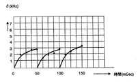
さらに、ADコンバータ20により、上記周波数成分をデジタル信号に変換したのち、PC22上のメモリに展開し、PC22内のタイマから得られた時間情報に対してメモリ内でプロットし、上述した方法によりメモリ上でδ値を算出した。この結果の一例を図6に示した。
図6においては、プロットを、式(6)
Further, after the frequency component is converted into a digital signal by the
In FIG. 6, the plot is represented by equation (6)
で近似した曲線を同時に示した。
図6には3本の非連続な曲線が示されているが、それぞれが拍動に対応している。即ち、図6では3回の拍動に対応したd値の変化を表している。本実施例においては、図6に示していない拍動を加えて合計20拍動分の測定を行い、式(7):
The curve approximated by is shown simultaneously.
FIG. 6 shows three discontinuous curves, each corresponding to a beat. That is, FIG. 6 shows a change in d value corresponding to three beats. In this example, a total of 20 beats are measured by adding beats not shown in FIG.
の平均値を求めたところ、その平均値は16.4×10⁴であった。
一方、上記と同一の被験者から採血を行い、マルヤス工業(株)製のビスコティック粘度計により血液の粘度を測定したところ、0.048poiseであった。
これらの結果、上記式(7)から、αの値は74.8×10⁴{=16.4×10⁴ /(0.048)-2}であった。
As a result, the average value was 16.4 × 10 4 .
On the other hand, blood was collected from the same subject as described above, and the viscosity of the blood was measured with a viscotic viscometer manufactured by Maruyasu Kogyo Co., Ltd. and found to be 0.048 poise.
As a result, from the above formula (7), the value of α was 74.8 × 10 4 {= 16.4 × 10 4 /(0.048) −2 }.
[評価試験]
上記本発明の血液粘度測定装置1による血液の粘度測定の正確性を、以下のようにして評価した。即ち、上記実施例と同一の方法で同一のα値を用いて測定した、異なる被験者の血液の粘度を、マルヤス工業(株)製ビスコティック粘度計を用いて測定した、上記異なる被験者から採取した血液の粘度(in vitro)に対して、プロットした。この結果を図7に示した。
[Evaluation test]
The accuracy of blood viscosity measurement by the blood
図7は、本実施例において測定した血液の粘度と、従来の方法で測定した血液の粘度と、の相関関係を示す図である。図7から、両者の手法により測定した血液の粘度がよく相関しており、本発明の血液粘度測定装置によれば、非侵襲でも正確に血液の粘度を測定することができることが確認された。 FIG. 7 is a diagram showing a correlation between blood viscosity measured in the present example and blood viscosity measured by a conventional method. From FIG. 7, it was confirmed that the blood viscosity measured by both methods is well correlated, and that the blood viscosity measuring apparatus of the present invention can accurately measure the blood viscosity even non-invasively.
なお、上記実施例においては、説明のため各測定ステップ毎に図にプロットし、図を用いて解析を進めたが、当然のことながら実用においては、これらの測定ステップは全てPC22および制御装置24によって自動的に行うことができる。
In the above-described embodiment, for the sake of explanation, each measurement step is plotted in a diagram and the analysis is performed using the diagram. However, in practice, these measurement steps are all performed by the
また、図示しないが、本発明の血液粘度測定装置1は液晶ディスプレイなどのディスプレイを備えておくのが好ましく、各測定ステップにおける、図3、4および6および、測定した血液の粘度を表示させることも可能である。ただし、図3、4および6などは特に表示する必要はなく、少なくとも測定した血液の粘度を表示する機能を有していればよい。
Although not shown, the blood
本発明の血液粘度測定装置によれば、非侵襲的に血液の粘度を測定することができ、得られた血液粘度の情報を例えば内臓疾患の判断に利用することができる。 According to the blood viscosity measuring apparatus of the present invention, blood viscosity can be measured non-invasively, and information on the obtained blood viscosity can be used for, for example, determination of visceral diseases.
1・・・生体
2・・・表皮
4・・・血管
10・・・血液粘度測定装置
12、102・・・発信器
14、104・・・受信器
16、106・・・ミキサ
18・・・スペクトラムアナライザ
20・・・ADコンバータ
22・・・PC
24・・・制御装置
100・・・血流測定装置
108・・・演算装置
DESCRIPTION OF
24...
Claims (4)
前記第1の超音波が前記生体に入射した後、前記血液を経由して前記生体の外部に出射された第2の超音波を受信する手段Bと、
前記血流によって前記第1の超音波と前記第2の超音波との間で生じたドップラー効果による、前記第1の超音波の第1の周波数と、前記第2の超音波の第2の周波数との差Δfの分布を測定する手段Cと、
前記差Δfの時間的変化を測定する手段Dと、
前記差Δfの時間的変化に基づいて、前記血管内における前記血液の流速分布を測定する手段Eと、
前記流速分布の時間的変化に基づいて前記血液の粘度を測定する手段Fと、
を具備する血液粘度測定装置。 Means A for non-invasively irradiating the first ultrasonic wave along the direction of blood flow in the blood vessel from the surface of the living body;
Means B for receiving a second ultrasonic wave emitted from the living body via the blood after the first ultrasonic wave is incident on the living body;
A first frequency of the first ultrasonic wave and a second frequency of the second ultrasonic wave due to the Doppler effect generated between the first ultrasonic wave and the second ultrasonic wave by the blood flow. Means C for measuring the distribution of the difference Δf from the frequency;
Means D for measuring the temporal change of the difference Δf;
Means E for measuring the flow velocity distribution of the blood in the blood vessel based on the temporal change of the difference Δf;
Means F for measuring the viscosity of the blood based on temporal changes in the flow velocity distribution;
A blood viscosity measuring apparatus comprising:
前記拍動の間隔と前記流速分布の時間的変化とを同期させる手段と、
を具備する請求項1記載の血液粘度測定装置。 Means for detecting the pulsation of the pulse;
Means for synchronizing the beat interval and the temporal change in the flow velocity distribution;
The blood viscosity measuring apparatus according to claim 1 comprising:
The blood viscosity measuring apparatus according to claim 3, wherein the means F measures the viscosity of the blood based on a temporal change in the thickness of the boundary layer.
Priority Applications (1)
| Application Number | Priority Date | Filing Date | Title |
|---|---|---|---|
| JP2005374367A JP4739945B2 (en) | 2005-12-27 | 2005-12-27 | Blood viscosity measuring device |
Applications Claiming Priority (1)
| Application Number | Priority Date | Filing Date | Title |
|---|---|---|---|
| JP2005374367A JP4739945B2 (en) | 2005-12-27 | 2005-12-27 | Blood viscosity measuring device |
Publications (2)
| Publication Number | Publication Date |
|---|---|
| JP2007175127A true JP2007175127A (en) | 2007-07-12 |
| JP4739945B2 JP4739945B2 (en) | 2011-08-03 |
Family
ID=38300918
Family Applications (1)
| Application Number | Title | Priority Date | Filing Date |
|---|---|---|---|
| JP2005374367A Expired - Fee Related JP4739945B2 (en) | 2005-12-27 | 2005-12-27 | Blood viscosity measuring device |
Country Status (1)
| Country | Link |
|---|---|
| JP (1) | JP4739945B2 (en) |
Cited By (4)
| Publication number | Priority date | Publication date | Assignee | Title |
|---|---|---|---|---|
| WO2010143272A1 (en) * | 2009-06-09 | 2010-12-16 | 独立行政法人産業技術総合研究所 | Device for examining vascular function |
| WO2010143271A1 (en) * | 2009-06-09 | 2010-12-16 | 独立行政法人産業技術総合研究所 | Device for examining vascular function |
| CN108007825A (en) * | 2017-12-29 | 2018-05-08 | 同济大学 | A kind of liquid viscosity test method based on drop mechanical oscillation |
| CN110196209A (en) * | 2018-04-08 | 2019-09-03 | 深圳市贝斯曼精密仪器有限公司 | A kind of blood viscosity detection method and device |
Families Citing this family (1)
| Publication number | Priority date | Publication date | Assignee | Title |
|---|---|---|---|---|
| KR102226406B1 (en) * | 2019-03-04 | 2021-03-11 | (주)아이에스엠 | Non-invasive viscosity measurement apparatus and method based on near-infrared imaging |
Citations (5)
| Publication number | Priority date | Publication date | Assignee | Title |
|---|---|---|---|---|
| JPH01209046A (en) * | 1988-02-17 | 1989-08-22 | Hitachi Ltd | Blood pressure measurement method and blood pressure monitor |
| WO2003015635A1 (en) * | 2001-08-20 | 2003-02-27 | Japan Science And Technology Corporation | Tissue identifying method in ultrasonography and ultrasonograph |
| JP2005160944A (en) * | 2003-12-05 | 2005-06-23 | Seiko Instruments Inc | Apparatus and method for measuring blood flow rate |
| JP2005288156A (en) * | 2004-03-09 | 2005-10-20 | Seiko Instruments Inc | Device for measuring blood rheology |
| JP2006166974A (en) * | 2004-12-13 | 2006-06-29 | National Institute Of Advanced Industrial & Technology | Hemodynamic characteristic measuring device |
-
2005
- 2005-12-27 JP JP2005374367A patent/JP4739945B2/en not_active Expired - Fee Related
Patent Citations (5)
| Publication number | Priority date | Publication date | Assignee | Title |
|---|---|---|---|---|
| JPH01209046A (en) * | 1988-02-17 | 1989-08-22 | Hitachi Ltd | Blood pressure measurement method and blood pressure monitor |
| WO2003015635A1 (en) * | 2001-08-20 | 2003-02-27 | Japan Science And Technology Corporation | Tissue identifying method in ultrasonography and ultrasonograph |
| JP2005160944A (en) * | 2003-12-05 | 2005-06-23 | Seiko Instruments Inc | Apparatus and method for measuring blood flow rate |
| JP2005288156A (en) * | 2004-03-09 | 2005-10-20 | Seiko Instruments Inc | Device for measuring blood rheology |
| JP2006166974A (en) * | 2004-12-13 | 2006-06-29 | National Institute Of Advanced Industrial & Technology | Hemodynamic characteristic measuring device |
Cited By (8)
| Publication number | Priority date | Publication date | Assignee | Title |
|---|---|---|---|---|
| WO2010143272A1 (en) * | 2009-06-09 | 2010-12-16 | 独立行政法人産業技術総合研究所 | Device for examining vascular function |
| WO2010143271A1 (en) * | 2009-06-09 | 2010-12-16 | 独立行政法人産業技術総合研究所 | Device for examining vascular function |
| JP5219228B2 (en) * | 2009-06-09 | 2013-06-26 | 独立行政法人産業技術総合研究所 | Vascular function testing device |
| JP5224221B2 (en) * | 2009-06-09 | 2013-07-03 | 独立行政法人産業技術総合研究所 | Vascular function testing device |
| US8500640B2 (en) | 2009-06-09 | 2013-08-06 | National Institute Of Advanced Industrial Science And Technology | Blood vessel function inspecting apparatus |
| US8657748B2 (en) | 2009-06-09 | 2014-02-25 | National Institute Of Advanced Industrial Science And Technology | Blood vessel function inspecting apparatus |
| CN108007825A (en) * | 2017-12-29 | 2018-05-08 | 同济大学 | A kind of liquid viscosity test method based on drop mechanical oscillation |
| CN110196209A (en) * | 2018-04-08 | 2019-09-03 | 深圳市贝斯曼精密仪器有限公司 | A kind of blood viscosity detection method and device |
Also Published As
| Publication number | Publication date |
|---|---|
| JP4739945B2 (en) | 2011-08-03 |
Similar Documents
| Publication | Publication Date | Title |
|---|---|---|
| ANGELSEN et al. | Transcutaneous measurement of blood flow velocity in the human aorta | |
| Nelson et al. | The Doppler signal: where does it come from and what does it mean? | |
| JP4206218B2 (en) | Cardiodynamic measurement device | |
| US10327737B2 (en) | System and method for acoustic radiation force creep-recovery and shear wave propagation elasticity imaging | |
| US11272901B2 (en) | Ultrasound blood-flow monitoring | |
| US20160345930A1 (en) | Blood pressure measurement device and blood pressure measurement method | |
| US20030204143A1 (en) | Sphygmogram measure method and device for two closed measured points | |
| JP2003159250A5 (en) | ||
| Ding et al. | A pulsed wave Doppler ultrasound blood flowmeter by PMUTs | |
| JP2005130969A (en) | Circulatory dynamic measuring instrument | |
| US11717255B2 (en) | Ultrasound blood-flow monitoring | |
| Nahar et al. | Influence of elastic tube deformation on flow behavior of a shear thinning fluid | |
| JP4716279B2 (en) | Blood viscosity measuring device | |
| JP4739945B2 (en) | Blood viscosity measuring device | |
| Browne et al. | Validation of a sensitivity performance index test protocol and evaluation of colour Doppler sensitivity for a range of ultrasound scanners | |
| Nawijn et al. | Stress-strain analysis of single ultrasound-driven microbubbles for viscoelastic shell characterization | |
| EP2034901B1 (en) | Global and local detection of blood vessel elasticity | |
| CN106963424A (en) | System and method for detecting arterial vessel viscoelasticity | |
| JP3820162B2 (en) | Cardiodynamic measurement device | |
| Pereira et al. | Characterization of a double probe for local pulse wave velocity assessment | |
| JP4754597B2 (en) | Cardiodynamic measurement device, cardiovascular sensor | |
| Wan et al. | In vivo hemodynamic evaluation based on transverse Doppler measurements of blood velocities and vessel diameter | |
| JP2008212746A (en) | Ultrasonic diagnostic equipment | |
| JP2004222754A (en) | Ultrasound diagnostic equipment | |
| US20240090875A1 (en) | System and Method for Non-Invasive Determination of Bladder Overactivity Using Ultrasound Vibrometry |
Legal Events
| Date | Code | Title | Description |
|---|---|---|---|
| A621 | Written request for application examination |
Free format text: JAPANESE INTERMEDIATE CODE: A621 Effective date: 20080129 |
|
| A977 | Report on retrieval |
Free format text: JAPANESE INTERMEDIATE CODE: A971007 Effective date: 20101026 |
|
| A131 | Notification of reasons for refusal |
Free format text: JAPANESE INTERMEDIATE CODE: A131 Effective date: 20101104 |
|
| A521 | Request for written amendment filed |
Free format text: JAPANESE INTERMEDIATE CODE: A523 Effective date: 20101203 |
|
| TRDD | Decision of grant or rejection written | ||
| A01 | Written decision to grant a patent or to grant a registration (utility model) |
Free format text: JAPANESE INTERMEDIATE CODE: A01 Effective date: 20110407 |
|
| A61 | First payment of annual fees (during grant procedure) |
Free format text: JAPANESE INTERMEDIATE CODE: A61 Effective date: 20110428 |
|
| R150 | Certificate of patent or registration of utility model |
Ref document number: 4739945 Country of ref document: JP Free format text: JAPANESE INTERMEDIATE CODE: R150 Free format text: JAPANESE INTERMEDIATE CODE: R150 |
|
| FPAY | Renewal fee payment (event date is renewal date of database) |
Free format text: PAYMENT UNTIL: 20140513 Year of fee payment: 3 |
|
| S111 | Request for change of ownership or part of ownership |
Free format text: JAPANESE INTERMEDIATE CODE: R313113 |
|
| R350 | Written notification of registration of transfer |
Free format text: JAPANESE INTERMEDIATE CODE: R350 |
|
| LAPS | Cancellation because of no payment of annual fees |