JP2007086500A - Display device - Google Patents
Display device Download PDFInfo
- Publication number
- JP2007086500A JP2007086500A JP2005276159A JP2005276159A JP2007086500A JP 2007086500 A JP2007086500 A JP 2007086500A JP 2005276159 A JP2005276159 A JP 2005276159A JP 2005276159 A JP2005276159 A JP 2005276159A JP 2007086500 A JP2007086500 A JP 2007086500A
- Authority
- JP
- Japan
- Prior art keywords
- display device
- display
- pixels
- curved surface
- microlenses
- Prior art date
- Legal status (The legal status is an assumption and is not a legal conclusion. Google has not performed a legal analysis and makes no representation as to the accuracy of the status listed.)
- Pending
Links
Images


Classifications
-
- G—PHYSICS
- G02—OPTICS
- G02B—OPTICAL ELEMENTS, SYSTEMS OR APPARATUS
- G02B3/00—Simple or compound lenses
- G02B3/0006—Arrays
-
- G—PHYSICS
- G02—OPTICS
- G02B—OPTICAL ELEMENTS, SYSTEMS OR APPARATUS
- G02B27/00—Optical systems or apparatus not provided for by any of the groups G02B1/00 - G02B26/00, G02B30/00
- G02B27/01—Head-up displays
- G02B27/017—Head mounted
- G02B27/0172—Head mounted characterised by optical features
-
- H—ELECTRICITY
- H04—ELECTRIC COMMUNICATION TECHNIQUE
- H04N—PICTORIAL COMMUNICATION, e.g. TELEVISION
- H04N23/00—Cameras or camera modules comprising electronic image sensors; Control thereof
- H04N23/50—Constructional details
- H04N23/53—Constructional details of electronic viewfinders, e.g. rotatable or detachable
-
- H—ELECTRICITY
- H04—ELECTRIC COMMUNICATION TECHNIQUE
- H04N—PICTORIAL COMMUNICATION, e.g. TELEVISION
- H04N5/00—Details of television systems
- H04N5/66—Transforming electric information into light information
-
- H—ELECTRICITY
- H10—SEMICONDUCTOR DEVICES; ELECTRIC SOLID-STATE DEVICES NOT OTHERWISE PROVIDED FOR
- H10F—INORGANIC SEMICONDUCTOR DEVICES SENSITIVE TO INFRARED RADIATION, LIGHT, ELECTROMAGNETIC RADIATION OF SHORTER WAVELENGTH OR CORPUSCULAR RADIATION
- H10F39/00—Integrated devices, or assemblies of multiple devices, comprising at least one element covered by group H10F30/00, e.g. radiation detectors comprising photodiode arrays
- H10F39/80—Constructional details of image sensors
- H10F39/806—Optical elements or arrangements associated with the image sensors
- H10F39/8063—Microlenses
-
- G—PHYSICS
- G02—OPTICS
- G02B—OPTICAL ELEMENTS, SYSTEMS OR APPARATUS
- G02B27/00—Optical systems or apparatus not provided for by any of the groups G02B1/00 - G02B26/00, G02B30/00
- G02B27/01—Head-up displays
- G02B27/0101—Head-up displays characterised by optical features
- G02B2027/0118—Head-up displays characterised by optical features comprising devices for improving the contrast of the display / brillance control visibility
-
- G—PHYSICS
- G02—OPTICS
- G02B—OPTICAL ELEMENTS, SYSTEMS OR APPARATUS
- G02B27/00—Optical systems or apparatus not provided for by any of the groups G02B1/00 - G02B26/00, G02B30/00
- G02B27/01—Head-up displays
- G02B27/017—Head mounted
- G02B2027/0178—Eyeglass type
Landscapes
- Physics & Mathematics (AREA)
- Engineering & Computer Science (AREA)
- Multimedia (AREA)
- Signal Processing (AREA)
- General Physics & Mathematics (AREA)
- Optics & Photonics (AREA)
- Liquid Crystal (AREA)
- Electroluminescent Light Sources (AREA)
Abstract
Description
本発明は、目の近点より近い距離からの単眼視又は両眼視による拡大観察を行うことができ、表示面の略全面に亘って明確に視認することができる表示装置に関するものである。 The present invention relates to a display device that can perform magnified observation by monocular or binocular vision from a distance closer to the eye's near point and can be clearly visually recognized over substantially the entire display surface.
従来の、この種の表示装置としては、例えば、特許文献1に記載されているようなものがある。特許文献1には、表示内容の片目による拡大観察が可能な表示装置に関するものが記載されている。この特許文献1に記載された表示装置は、「2次元的に配列された画素を有する自己発光型の画像表示手段と、該画像表示手段の各画素に対応してその画素の一部に有する微小発光点と、前記2次元的に配列された各微小発光点からの射出光を導く微小光学素子とを備え、各微小発光点とそれに対応する微小光学素子を結ぶ光軸が目の近点より近い所定の点で実質的に交わり、該微小光学素子がそれに対応する微小発光点の虚像を該所定の点から明視の距離以上離れた位置に結ぶように配置されている」ことを特徴としている。
As a conventional display device of this type, for example, there is a device described in
このような構成を有する特許文献1に記載の表示装置によれば、「表示内容の近距離での単眼視による拡大観察が可能な表示装置の軽量化及び薄型化を図ることができる」という効果が期待される。
しかしながら、特許文献1に記載されている従来の表示装置においては、複数の画素が平面上に2次元的に配列されており、そのような各画素に対応して複数の微小光学素子であるマイクロレンズも同様に、平面上に2次元的に配列された構成となっている。そのため、目から各画素までの距離が、中央部分において最も短く、その中央部分から放射方向外側に移るに従って逐次的に長くなることから、中央部分をはっきりさせると、半径方向外側部分がぼやけることになり、視認する像を隅から隅までスッキリ見ることができないという問題があった。
However, in the conventional display device described in
解決しようとする問題点は、従来の表示装置では、複数の画素及び複数のマイクロレンズが平面上に2次元的に配列されているため、像を隅から隅までスッキリ見ることができない、という点である。 The problem to be solved is that in a conventional display device, a plurality of pixels and a plurality of microlenses are two-dimensionally arranged on a plane, so that the image cannot be clearly seen from corner to corner. It is.
本発明の表示装置は、所定の曲面上に配列された複数の画素を有する画像表示手段と、その画像表示手段の複数の画素に対応するよう各画素に対向して所定の曲面上に配列された複数のマイクロレンズと、を備え、複数のマイクロレンズから出た光を目に集来させるようにすることにより明視の距離以上離れた位置に虚像を結ぶようにしたことを最も主要な特徴とする。 The display device of the present invention has an image display means having a plurality of pixels arranged on a predetermined curved surface, and is arranged on the predetermined curved surface facing each pixel so as to correspond to the plurality of pixels of the image display means. The most important feature is that a virtual image is formed at a position more than the distance of clear vision by allowing the light emitted from the plurality of microlenses to gather in the eye. And
本発明の表示装置によれば、複数の画素と複数のマイクロレンズが、それぞれに対向して所定の曲面上に配列され、複数のマイクロレンズから出た光を目に集来させるようにしたため、所定の虚像を隅から隅までスッキリと明瞭に見ることができる。 According to the display device of the present invention, the plurality of pixels and the plurality of microlenses are arranged on a predetermined curved surface so as to face each other, and the light emitted from the plurality of microlenses is gathered in the eye. A predetermined virtual image can be clearly and clearly seen from corner to corner.
所定の虚像を隅から隅までスッキリと明瞭に見ることができる表示装置を、簡単な構成によって実現した。 A display device that can clearly and clearly view a predetermined virtual image from corner to corner has been realized with a simple configuration.
以下、本発明の実施の形態を、添付図面を参照して説明する。図1〜図12は、本発明の実施の形態の例を説明するものである。即ち、図1は本発明の表示装置の第1の実施の例を示す説明図、図2は第2の実施の例を示す説明図、図3は第3の実施の例を示す説明図、図4は本発明に係る表示装置の曲面の説明図、図5は本発明に係る画像表示手段の一実施例を示す説明図、図6は眼鏡に適用した説明図、図7は眼鏡の要部を示す説明図、図8は眼鏡の使用状態を示す説明図、図9は電子スチルカメラに適用した一実施例の正面側斜視図、図10は同じく背面側斜視図、図11は電子スチルカメラの使用状態を示す説明図、図12はビデオカメラの要部を断面して示す説明図である。 Hereinafter, embodiments of the present invention will be described with reference to the accompanying drawings. FIGS. 1-12 demonstrates the example of embodiment of this invention. 1 is an explanatory diagram showing a first embodiment of the display device of the present invention, FIG. 2 is an explanatory diagram showing a second embodiment, FIG. 3 is an explanatory diagram showing a third embodiment, 4 is an explanatory view of a curved surface of the display device according to the present invention, FIG. 5 is an explanatory view showing an embodiment of the image display means according to the present invention, FIG. 6 is an explanatory view applied to eyeglasses, and FIG. FIG. 8 is an explanatory diagram showing the usage state of the glasses, FIG. 9 is a front perspective view of an embodiment applied to an electronic still camera, FIG. 10 is a rear perspective view, and FIG. 11 is an electronic still. FIG. 12 is an explanatory view showing a cross section of the main part of the video camera.
図1に示すように、本発明の表示装置1は、複数の画素を有する画像表示手段の第1の具体例を示す自己発光型の表示素子である有機EL(エレクトロルミネッセンス)ディスプレイ2と、その有機ELディスプレイ2の一面に一体的に設けられた複数のマイクロレンズ3とを備えて構成されている。有機ELディスプレイ2の少なくとも一面は、所定の曲面の第1の具体例を示す球面(球体の一部分)8として形成されている。この球面8に複数のマイクロレンズ3が、その略全面に亘って整列されて設けられている。
As shown in FIG. 1, a
ここで、「所定の曲面」とは、この実施例に係る「球面」(曲率半径ρが一定)8に限定されるものではなく、曲率半径ρの値を変えることによって形成される各種の大きさの球面を含むことは勿論のこと、これ以外にも、例えば、部位によって曲率を変えた「非球面」を含むものである。ここで、「非球面」とは、放物線、双曲線、二次曲線又はこれらに近似した曲線をいうものとする。また、所定の曲面としては、円筒の一部を切り取ったような「シリンドリカルな曲面」であってもよい。所定の曲面を「シリンドリカルな曲面」とした場合には、平面である場合よりも見易くなり、かつ、平面を一方向に曲げるだけでよいので、球面とする場合よりも製造し易い、という利点がある。 Here, the “predetermined curved surface” is not limited to the “spherical surface” (the radius of curvature ρ is constant) 8 according to this embodiment, but various sizes formed by changing the value of the radius of curvature ρ. In addition to this, it also includes, for example, an “aspherical surface” whose curvature is changed depending on the part. Here, “aspherical surface” refers to a parabola, a hyperbola, a quadratic curve, or a curve approximated thereto. The predetermined curved surface may be a “cylindrical curved surface” obtained by cutting a part of a cylinder. When the predetermined curved surface is a “cylindrical curved surface”, it is easier to see than when it is a plane, and it is only necessary to bend the plane in one direction. is there.
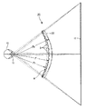
本発明の表示装置1に係る「曲面」について、更に詳しく説明すると、図4に示す如くである。図4において、符号10は目、符号11は瞳孔、符号ALは目10の視線の中心(光軸)を示し、符号SFは、概略目10の位置にある光軸ALと垂直をなす平面を示している。本発明の曲面は、表示装置1の表示画面の中央部に対して両側の周辺部が、視覚する方向である光軸AL方向に対して近い位置にある曲面となっている。即ち、平面SFから表示画面の中央部までの距離をL0、平面SFから表示画面の中央部より放射方向(半径方向)外側の任意の中途部までの距離をL1、平面SFから表示画面の周辺部までの距離をL2とすると、L0>L1>l2の関係がある。
The “curved surface” according to the
このような所定の曲面を有する有機ELディスプレイ2の一面である凹側の球面8に、そこに配列された複数の画素に対応するよう各画素に対向して、それぞれが一対一の関係となるように複数のマイクロレンズ3が設けられている。
The concave
有機ELディスプレイ2は、例えば、図5に示すような構造を備えて構成されている。即ち、有機ELディスプレイ2は、第1のガラス基板4と、この第1のガラス基板4の一面に設けられた複数の有機EL素子5及びTFT(薄膜トランジスタ)6と、これらの有機EL素子5等を第1のガラス基板4との間で挟んで保持する第2のガラス基板7と、を備えて構成されている。第2のガラス基板7の凹側の面により、上記所定の曲面をなす球面8が構成されている。
For example, the
有機ELディスプレイ2の有機EL素子5は、3原色をなす赤色有機EL素子5aと緑色有機EL素子5bと青色有機EL素子5cとの3種類の色の組み合わせを備えている。これら3色の有機EL素子5a〜5cが、球面8の中央部分においては適当な色の1個の有機EL素子5が配置され、その中心の1個から半径方向外側へ必要な数の列だけ、周方向へ所定間隔によって3色の有機EL素子5a〜5cが順次繰り返すように配置されている。これら有機EL素子5a〜5cのそれぞれに対向するよう、一対一の関係をもって重なり合うように、複数のマイクロレンズ3が球面8上に配置されて一体的に構成されている。
The organic EL element 5 of the
複数のマイクロレンズ3は、それぞれが凸レンズの半面を形成するような形状として構成されている。これら複数のマイクロレンズ3から出た光を、この表示装置1を使用する人の目に集来させるようにすることにより、明視の距離以上離れた位置に虚像を結ぶようにしている。即ち、すべてのマイクロレンズ3の光軸は、表示装置1を使用する人の目10の瞳孔11又はその瞳孔11の近傍で実質的に交わるように設定されている。このように複数のマイクロレンズ3を、適当な曲率半径ρを有する球面上に配置することにより、目10のピントが合わせられる距離(例えば250mm)よりもはるかに目に近い位置(5mm〜40mm)においてピントを合わせ、その虚像を明視の距離以上離れた位置に結ぶことが可能となる。
The plurality of
人の目は、平均的には瞳孔11から80mm〜100mmの範囲に近点と呼ばれる生理上、特に意識することなくピントを合わすことができる限界点が想定される。そのため、明視の距離が250mmであるとすると、表示面と所定の点である目(瞳孔)との距離は5〜50mm程度、所定の点から虚像が結ばれる位置までの距離は250mm〜∞となり、好ましくは1〜5mに設定するとよい。
On the average, the human eye is assumed to be a critical point called a near point in the range of 80 mm to 100 mm from the
また、有機EL素子5a〜5cの第2のガラス基板7側には、TFT(薄膜トランジスタ)6のカソードをなす半透過膜(電極)14が設けられている。そして、各有機EL素子5a〜5cの第2のガラス基板7と反対側には、TFT6のアノードをなすメタル電極15a〜15cが設けられている。これらメタル電極15a〜15c及び半透過膜14とその他の配線等により、各有機EL素子5a〜5cに対応させて設けられたTFT(薄膜トランジスタ)6a〜6cが構成されている。
A semi-transmissive film (electrode) 14 that forms a cathode of the TFT (thin film transistor) 6 is provided on the second glass substrate 7 side of the organic EL elements 5a to 5c. Further,
かくして、任意の有機EL素子5a〜5cに対応して設けたTFT6a〜6cのメタル電極15a〜15cと半透過膜14との間に電圧を印加することにより、それぞれの有機EL素子5a〜5cが持つ色の光を発光することができる。即ち、赤色有機EL素子5aにおいては赤色の光が発光され、緑色有機EL素子5bにおいては緑色の光が発光され、青色有機EL素子5cにおいては青色の光が発光される。これらの発光によって生じた各色の光は、そのまま半透過膜14と第2のガラス基板7を透過し、それぞれに対向するように設置されたマイクロレンズ3を透過して外部に放射される。
Thus, by applying a voltage between the
これと同時に、それぞれの発光によって生じた光のうち、背面の第1のガラス基板4側に向かう光は、第1のガラス基板4側に位置するメタル電極15aによって第2のガラス基板7側に反射される。このようにメタル電極15aで反射された光は、正面側に放射された光に重畳され、一体となって半透過膜14及び第2のガラス基板7を透過し、その前方に設置されたマイクロレンズ3を経て外部に放射される。
At the same time, among the light generated by each light emission, the light directed toward the first glass substrate 4 on the back side is moved to the second glass substrate 7 side by the
このような構成を有する表示装置1によれば、図1に示すように、各マイクロレンズ3から出る光を、目10の瞳孔11又はその近傍で実質的に交わるように配置することにより、近すぎる表示画面である球面8を認識することなく、マイクロレンズアレイによりルーペと同じ原理で拡大された虚像17を観察することができる。しかも、本発明によれば、複数のマイクロレンズ3を球面8上に配置し、瞳孔11から表示画面の中央までの距離と瞳孔11から表示画面の両端までの距離を等しくするか若しくは両距離の差を少なくすることにより、表示画面である球面8を隅から隅まですっきりと視認することが可能となる。即ち、表示画面を球面形状としたため、小さな表示装置1でありながら、大きな光学系とすることなく大きな虚像17を明視することができる。
According to the
図2は、本発明の第2の実施例を示すものである。この第2の実施例に示す表示装置20は、前記実施例における球面8上に配置された複数のマイクロレンズ3と目10との間に、光学レンズの一具体例を示す凸レンズ21を配置し、虚像17を更に拡大して見ることができるようにしたものである。
FIG. 2 shows a second embodiment of the present invention. In the
凸レンズ21は、その光軸を有機ELディスプレイ22の中心と一致させるように配置されている。この場合、凸レンズ21は、入射する光線を内側に収束させて出射するため、その収束された光線が目10の瞳孔11又はその近傍に集来される。その結果、有機ELディスプレイ22の複数の有機EL素子5a〜5cと複数のマイクロレンズ3とで表示される球面形状の表示画面に表示される画像を、凸レンズ21を入れることで更に拡大することができると共に、その拡大された虚像17をしっかりと観察することができる。しかも、目10と有機ELディスプレイ22の間に光学レンズを入れたとしても、その光学レンズで光線の進路を強く曲げなくてすむため、その虚像17を自然な感覚で見ることができ、その虚像17を見易くすることができる。
The
図3は、本発明の第3の実施例を示すものである。この第3の実施例に示す表示装置30は、前記第1の実施例における有機ELディスプレイ2の表示画面である球面8の曲率を変更可能に構成したものである。この実施例に係る表示装置30の場合には、有機ELディスプレイ32の表示画面である球面8の曲率を変更可能として、その球面8の曲率半径ρを変えることにより、発生する虚像17の拡大幅を大きくしたり、小さくしたりして、様々な大きさの虚像17を観察することが可能となる。
FIG. 3 shows a third embodiment of the present invention. The
例えば、球面8の曲率半径ρを小さく曲率半径ρs(ρ>ρs)とすると、その球面8の凹み量が大きくなり、これにより、観察される虚像17を更に拡大(ズーム機能)することができる。これとは逆に、球面8の曲率半径ρを大きく曲率半径ρt(ρ<ρt)とすると、その球面8の凹み量が小さくなり、これにより、観察される虚像を小さくすることができる。
For example, if the curvature radius ρ of the
この実施例では、画像表示手段として自己発光型の表示素子である有機ELディスプレイ2を用いた例について説明したが、本発明はこれに限定されるものではなく、例えば、バックライトを用いた液晶ディスプレイを用いることができる。液晶ディスプレイは、複数の液晶セルを有する液晶表示素子と、この液晶表示素子の背面又は側面に配置されて液晶画素である各液晶セルに光線を照射する発光部としてのバックライト等を備えて構成されている。
In this embodiment, an example in which the
液晶ディスプレイの種類としては、相対する2枚のガラス板の内面に形成される表示電極の形で分類すると、マトリクス形とセグメント形等がある。また、透過形でディスプレイを行う液晶セルでは、何れの電極も透明電極が用いられ、反射形では、一方が透明電極で、他方の電極には反射膜が用いられている。このような構成を有する液晶ディスプレイ(LCD)を用い、電極間に加えられる電圧を制御して、光線の透過と不透過を制御するか、又は光線の透過量を制御することにより、表示画面に所望の像を表示することができる。 Types of liquid crystal displays include a matrix type and a segment type when classified according to the shape of display electrodes formed on the inner surfaces of two opposing glass plates. Further, in a liquid crystal cell that performs display in a transmissive type, each electrode uses a transparent electrode, and in the reflective type, one is a transparent electrode and the other electrode is a reflective film. Using a liquid crystal display (LCD) having such a configuration, the voltage applied between the electrodes is controlled to control the transmission and non-transmission of light, or the amount of light transmission can be controlled on the display screen. A desired image can be displayed.
なお、画像表示手段としては、これらの実施例の他にも、例えば、プラズマディスプレイパネル(PDP)は勿論のこと、ライトエミッティングダイオード(LED)、エレクトロクロミックディスプレイ(ECD)、蛍光表示管等を用いることができる。 In addition to these embodiments, the image display means includes, for example, a plasma display panel (PDP), a light emitting diode (LED), an electrochromic display (ECD), a fluorescent display tube, and the like. Can be used.
図6〜図8は、上述したような構成を有する表示装置1を、眼鏡レンズ41と一体に構成した実施の例を説明するものである。表示装置1は、眼鏡レンズ41の中央部より少々下方に配置されて一体的に構成されている。図6に示すように、一般に、人の目10の視野は、水平線HLを基準にすると、上方の上視野は約60°、下方の下視野も約60°である。そして、目10の瞳孔11から眼鏡レンズ40の内面までの距離は約2mmである。このような目10の前に眼鏡レンズ41を介在させて、1m(メートル)先に幅1mの虚像からなる画面を表示するものとすると、目10と表示装置1との関係は、次のように設定することができる。
FIGS. 6-8 demonstrates the Example which comprised the
即ち、眼鏡レンズ41に対して表示装置1は、その中心線(中心部において垂直に延在する線)CLが水平線HLとなす角度αが5〜10°となるように設定する。そして、中心線CLを中心として、その上下に必要な領域を占めるように任意の角度範囲β(β=上領域βa+下領域βd)を設定する。この実施例では、上領域βaと下領域βdは等しい角度とされていて、ともに約25度である。
That is, the
図7は、図6に示した眼鏡レンズ41を用いた眼鏡40を示すものである。この眼鏡40の構成は、一般の眼鏡と同様であり、一対の眼鏡レンズ41,41と、両眼鏡レンズ41,41を保持する眼鏡フレーム42と、を備えて構成されている。眼鏡フレーム42は、一対の眼鏡レンズ41,41を保持する一対の枠部43,43と、両枠部43,43の内側部分を連結するブリッジ44と、両枠部43,43の外側部分に設けられたヨロイ45と、各ヨロイ45に回動自在に支持されたテンプル46等を有している。
FIG. 7 shows a
各眼鏡レンズ41に内蔵された表示装置1には、酸化インジウム等によって形成された複数の透明電極48の一端が接続されている。複数の透明電極48の他端は、枠体43側に延在され、その枠体の内面に設けた接続端子に接続されている。枠体43の接続端子には、リード線49の一端が電気的に接続されている。そのリード線49の他端は、ヨロイ45及びテンプル46を貫通して、そのテンプル46の後部から外部に引き出されている。
One end of a plurality of
このような構成を有する眼鏡(ヘッドマウントディスプレイ装置:HMD)40を用いることにより、図8に示すように、素子面である表示画面から離れた位置に、マイクロレンズのレンズ作用によって大きく拡大された虚像17を観察することができる。なお、図7に図示した眼鏡レンズ41の表示装置1に表示したヨットの画像は、その部分において実際に存在するものではなく、あくまでも説明のために模式的に描いたものであり、その虚像は図8に示すような状態で見ることができる。
By using the spectacles (head mounted display device: HMD) 40 having such a configuration, as shown in FIG. 8, it was greatly enlarged by the lens action of the micro lens at a position away from the display screen which is the element surface. The
図9〜図11は、本発明に係る表示装置1が適用された電子機器の第1の実施例を示す電子スチルカメラを現した図である。電子スチルカメラ50は、偏平で横長の筐体からなるカメラ本体51と、このカメラ本体51に内蔵されると共に撮影レンズ52が露出されたレンズ装置と、同じくカメラ本体51に内蔵されると共にレンズ装置等を駆動制御する制御装置と、レンズ装置によって得られた撮像を表示する表示パネル53等を備えて構成されている。
9 to 11 are views showing an electronic still camera showing a first embodiment of an electronic apparatus to which the
電子スチルカメラ50のレンズ装置は、カメラ本体51の正面から見て右側に内蔵されており、その正面の右上部に撮影レンズ52が配置されている。その撮影レンズ52に対応してカメラ本体51の背面には、電子ビューファインダ54が配置されている。この電子ビューファインダ54と表示パネル53には、被写体に対応した同一の像が写し出される。表示パネル53としては、例えば、液晶ディスプレイ等のフラットパネルディスプレイを用いることができる。更に、カメラ本体51の背面であって、表示パネル53の側方には、表示パネル53の表示画面を切り換えたり、その画面内の機能を選択したりすることができる操作ボタン55が設けられている。また、カメラ本体51の上面には、静止画を撮影することができるシャッタボタン56が配置されている。
The lens device of the electronic still
このような構成を有する電子スチルカメラ50に対して、本発明の表示装置1は、電子ビューファインダ54に適用することができる。その電子ビューファインダ54の覗き窓に表示装置1を配置することにより、図11に示すように、素子面である表示画面から離れた位置に、マイクロレンズのレンズ作用によって大きく拡大された虚像17を観察することができる。なお、図10に図示した電子スチルカメラ50の電子ビューファインダ54に表示した人の顔の画像は、その部分において実際に存在するものではなく、あくまでも説明のために模式的に描いたものである。
For the electronic still
図12は、本発明に係る表示装置1の第3の実施例を適用した撮像装置を示すもので、所定の曲面をなす略球面の曲率半径を変更可能な曲面変更手段を設けたものである。この実施例の撮像装置としては、カメラ一体型VTR(ビデオテープレコーダ)60を現しているが、記録媒体は磁気テープ等のテープ状記録媒体に限定されるものではなく、光ディスクや光磁気ディスクその他のディスク状記録媒体を適用できることは勿論であり、情報の記録及び/又は再生が可能な記録媒体であれば、その他の形式の記録媒体であってもよいことは勿論である。
FIG. 12 shows an imaging apparatus to which the third embodiment of the
カメラ一体型VTR60は、偏平で横長の筐体からなるカメラ本体61を備えている。カメラ本体61の正面の上部にはレンズ装置62が配置され、このレンズ装置の後方に、曲面の変更可能な表示装置1を有するビューファインダ63が設けられている。そして、ビューファインダ63の覗き窓64が、カメラ本体61の背面に設けられている。符号65は、覗き窓64に保持された光学ガラスである。
The camera-integrated
ビューファインダ63は、表示部である表示装置1と、この表示装置1の曲面(球面の曲率)を変更可能な曲面変更手段70とを備えて構成されている。この表示装置1は、人の目10に対向されるマイクロレンズ3の有る面と反対側の面に付加される圧力を変更することにより、その圧力の大きさに応じて曲面の曲率(曲率半径)を変更することができる構成となっている。
The
曲面変更手段70は、表示装置1を保持する保持部71と、この保持部71の液室72内の圧力を調整可能な圧力調整部73と、この圧力調整部73と保持部71の液室72とを連通する接続パイプ74等を備えて構成されている。保持部71は、正面に円形の開口部75を有し、且つ内部に液室72が形成された中空のケース体からなる。この保持部71の開口部75に表示装置1が嵌合されて固定されている。表示装置1は、液室72の内側へ凸となる状態で配置されていると共に、その外周縁を接着剤で開口部75の内周面に貼着することにより液密に固着されて一体的に構成されている。
The curved
圧力調整部73は、接続パイプ74によって保持部71の液室72と連通されたシリンダ76と、このシリンダ76の穴内に摺動可能に挿入されたピストン77と、このピストン77に一端が固定され且つ他端がシリンダ76の端面とカメラ本体61の背面を貫通して外部に突出されたねじ軸78と、このねじ軸78の突出端に設けられた操作ツマミ79を備えている。液室72とシリンダ76と接続パイプ74の内部には、圧力を伝達可能な媒体の一具体例を示す油や水等の動力伝達媒体80が充填されている。
The
かくして、図12において、操作ツマミ79を反時計方向に回して、ピストン77を図中右側に移動すると、シリンダ76内の動力伝達媒体(液体)80の圧力が減少し、その容積の増加分だけ液室72内の動力伝達媒体80の一部が流入する。これにより、液室72内の圧力が低下するため、表示装置1それ自体が持っている弾性によって表示装置1が、実線で示す状態から二点鎖線で示す状態に復帰する方向に変化する。そして、表示装置1の表示画面が、その曲面の曲率半径を小さくするように変形する。その結果、前述したように、マイクロレンズのレンズ作用によって大きく拡大された虚像17を観察することができる。
Thus, in FIG. 12, when the
これに対して、図12において、操作ツマミ79を時計方向に回して、ピストン77を図中左側に移動すると、シリンダ76内の動力伝達媒体80の圧力が増加し、その容積の減少分だけ動力伝達媒体80が液室72内に流入する。これにより、液室72内の圧力が上昇するため、表示装置1それ自体が持っている弾性に抗して表示装置1が、二点鎖線で示す状態から実線で示す状態に変化する。そして、表示装置1の表示画面が、その曲面の曲率半径を大きくするように変形する。その結果、前述したように、マイクロレンズのレンズ作用によって大きく拡大された虚像17を小さくして観察することができる。
On the other hand, in FIG. 12, when the
この実施例によれば、表示装置1の所定の曲面である略球面を曲面変更手段70によって変更可能とすることにより、ビューファインダ63の視度調整の役目をさせたり、見る画面の大きさを調整したりすることができる。例えば、ビューファインダ63の画面の大きさを14インチ〜50インチの間で変更可能とした場合には、14インチで見るか、50インチで見るかを自由に決定し、また、任意の大きさに調整して見ることができる。なお、この実施例では、ビューファインダ63の目の位置を固定する場合について説明したが、眼鏡型の表示装置(ヘッドマウントディスプレイ装置)に適用できることは勿論である。
According to this embodiment, the substantially spherical surface, which is a predetermined curved surface of the
以上説明してきたように、本発明の表示装置によれば、複数の画素と複数のマイクロレンズをそれぞれ対向させて所定の曲面上に配列し、複数のマイクロレンズから出た光を目に集来させるようにしたため、所定の虚像を隅から隅までスッキリと明瞭に見ることができる。そのため、従来のこの種の装置には無い小型、軽量であって、精細度が高く、しかも大画面の虚像を観察することができるモバイルディスプレイ並びにウェアラブルディスプレイを実現することができる。 As described above, according to the display device of the present invention, a plurality of pixels and a plurality of microlenses are arranged on a predetermined curved surface so as to face each other, and light emitted from the plurality of microlenses gathers in the eyes. Therefore, the predetermined virtual image can be clearly and clearly seen from corner to corner. Therefore, it is possible to realize a mobile display and a wearable display that are small and light, which are not found in this type of conventional device, have high definition, and can observe a virtual image on a large screen.
本発明は、前述しかつ図面に示した実施の形態に限定されるものではなく、その要旨を逸脱しない範囲内で種々の変形実施が可能である。例えば、前記実施例においては、電子スチルカメラやビデオ一体型VTRに適用した例について説明したが、その他の撮像装置に適用できることは勿論のこと、眼鏡型の他にもゴーグル型のディスプレイ装置やその他の装置のための表示装置として適用できるものである。 The present invention is not limited to the embodiment described above and shown in the drawings, and various modifications can be made without departing from the scope of the invention. For example, in the above-described embodiment, an example in which the present invention is applied to an electronic still camera or a video-integrated VTR has been described. It can be applied as a display device for these devices.
1,20,30…表示装置、 2,22,32…有機ELディスプレイ(画像表示手段)、 3…マイクロレンズ、 4…第1のガラス基板、 5…有機EL素子、 7…第2のガラス基板、 8…球面(所定の曲面)、 10…目、 11…瞳孔、 17…虚像、 21…凸レンズ(光学レンズ)、 40…眼鏡、 41…眼鏡レンズ、 42…眼鏡フレーム、 50…電子スチルカメラ(撮像装置)、 54…電子ビューファインダ、 60…カメラ一体型VTR(撮像装置)、 63…ビューファインダ、 70…曲面変更手段、 71…保持部、 72…液室、 73…圧力調整部、 74…接続パイプ、 80…動力伝達媒体(液体)
DESCRIPTION OF
Claims (8)
前記画像表示手段の前記複数の画素に対応するよう各画素に対向して前記所定の曲面上に配列された複数のマイクロレンズと、を備え、
前記複数のマイクロレンズから出た光を目に集来させるようにすることにより明視の距離以上離れた位置に虚像を結ぶようにしたことを特徴とする表示装置。 Image display means having a plurality of pixels arranged on a predetermined curved surface;
A plurality of microlenses arranged on the predetermined curved surface facing each pixel so as to correspond to the plurality of pixels of the image display means,
A display device characterized in that a virtual image is formed at a position more than a distance of clear vision by allowing light emitted from the plurality of microlenses to gather in an eye.
Priority Applications (2)
| Application Number | Priority Date | Filing Date | Title |
|---|---|---|---|
| JP2005276159A JP2007086500A (en) | 2005-09-22 | 2005-09-22 | Display device |
| US11/523,549 US7446941B2 (en) | 2005-09-22 | 2006-09-19 | Display apparatus |
Applications Claiming Priority (1)
| Application Number | Priority Date | Filing Date | Title |
|---|---|---|---|
| JP2005276159A JP2007086500A (en) | 2005-09-22 | 2005-09-22 | Display device |
Publications (1)
| Publication Number | Publication Date |
|---|---|
| JP2007086500A true JP2007086500A (en) | 2007-04-05 |
Family
ID=37973528
Family Applications (1)
| Application Number | Title | Priority Date | Filing Date |
|---|---|---|---|
| JP2005276159A Pending JP2007086500A (en) | 2005-09-22 | 2005-09-22 | Display device |
Country Status (2)
| Country | Link |
|---|---|
| US (1) | US7446941B2 (en) |
| JP (1) | JP2007086500A (en) |
Cited By (18)
| Publication number | Priority date | Publication date | Assignee | Title |
|---|---|---|---|---|
| JP2011215550A (en) * | 2010-04-02 | 2011-10-27 | Olympus Corp | Display device, electronic apparatus, mobile electronic apparatus, mobile phone, and imaging device |
| JP2014130218A (en) * | 2012-12-28 | 2014-07-10 | Japan Display Inc | Display device |
| WO2015008530A1 (en) * | 2013-07-16 | 2015-01-22 | ソニー株式会社 | Display device |
| US9316834B2 (en) | 2011-11-24 | 2016-04-19 | Panasonic Intellectual Property Management Co., Ltd. | Head-mounted display device with foveated pixels |
| KR20160087948A (en) * | 2015-01-14 | 2016-07-25 | 삼성디스플레이 주식회사 | Head mounted display apparatus |
| JPWO2014167934A1 (en) * | 2013-04-11 | 2017-02-16 | ソニー株式会社 | Image display device and display device |
| CN106464861A (en) * | 2013-11-25 | 2017-02-22 | 特塞兰德有限责任公司 | Immersive compact display glasses |
| JP2017510212A (en) * | 2013-12-17 | 2017-04-06 | マースピアル ホールディングス インコーポレイテッド | Integrated micro-optic imager, processor and display {INTEGRATED MICROOPTIC IMAGER, PROCESSOR AND DISPLAY} |
| JP2017146372A (en) * | 2016-02-15 | 2017-08-24 | セイコーエプソン株式会社 | Electro-optical device and electronic apparatus |
| US9952435B2 (en) | 2013-07-16 | 2018-04-24 | Sony Corporation | Display apparatus having curved image forming apparatus |
| JP2018128683A (en) * | 2018-02-28 | 2018-08-16 | セイコーエプソン株式会社 | Electro-optic device and electronic apparatus |
| WO2019044501A1 (en) * | 2017-09-04 | 2019-03-07 | 富士フイルム株式会社 | MOUNTED |
| JP2019040165A (en) * | 2017-08-29 | 2019-03-14 | 国立大学法人 奈良先端科学技術大学院大学 | Display device |
| US10663736B2 (en) | 2013-04-11 | 2020-05-26 | Sony Corporation | Image display device and display apparatus |
| US11073701B2 (en) | 2016-07-06 | 2021-07-27 | Panasonic Intellectual Property Management Co., Ltd. | Head-mounted display device |
| JP2023528097A (en) * | 2020-03-19 | 2023-07-04 | 京東方科技集團股▲ふん▼有限公司 | Display device and its display method |
| WO2025004382A1 (en) * | 2023-06-30 | 2025-01-02 | 株式会社ソニー・インタラクティブエンタテインメント | Head-mounted display |
| US12471418B2 (en) | 2021-07-13 | 2025-11-11 | Japan Display Inc. | Display device |
Families Citing this family (33)
| Publication number | Priority date | Publication date | Assignee | Title |
|---|---|---|---|---|
| US10359545B2 (en) | 2010-10-21 | 2019-07-23 | Lockheed Martin Corporation | Fresnel lens with reduced draft facet visibility |
| US8781794B2 (en) | 2010-10-21 | 2014-07-15 | Lockheed Martin Corporation | Methods and systems for creating free space reflective optical surfaces |
| US9632315B2 (en) | 2010-10-21 | 2017-04-25 | Lockheed Martin Corporation | Head-mounted display apparatus employing one or more fresnel lenses |
| MX2013006722A (en) * | 2010-12-16 | 2014-01-31 | Lockheed Corp | Collimating display with pixel lenses. |
| WO2013013230A2 (en) * | 2011-07-21 | 2013-01-24 | Jonathan Arnold Bell | Wearable display devices |
| US9829715B2 (en) | 2012-01-23 | 2017-11-28 | Nvidia Corporation | Eyewear device for transmitting signal and communication method thereof |
| JP6071215B2 (en) * | 2012-02-24 | 2017-02-01 | キヤノン株式会社 | Optical viewfinder and optical apparatus using the same |
| US20150070770A1 (en) * | 2012-04-12 | 2015-03-12 | Pioneer Corporation | Optical element, head-up display and light source unit |
| US9841537B2 (en) | 2012-07-02 | 2017-12-12 | Nvidia Corporation | Near-eye microlens array displays |
| US9557565B2 (en) | 2012-07-02 | 2017-01-31 | Nvidia Corporation | Near-eye optical deconvolution displays |
| USRE47984E1 (en) | 2012-07-02 | 2020-05-12 | Nvidia Corporation | Near-eye optical deconvolution displays |
| US9494797B2 (en) | 2012-07-02 | 2016-11-15 | Nvidia Corporation | Near-eye parallax barrier displays |
| US9582075B2 (en) | 2013-07-19 | 2017-02-28 | Nvidia Corporation | Gaze-tracking eye illumination from display |
| US9880325B2 (en) | 2013-08-14 | 2018-01-30 | Nvidia Corporation | Hybrid optics for near-eye displays |
| US9454008B2 (en) * | 2013-10-07 | 2016-09-27 | Resonance Technology, Inc. | Wide angle personal displays |
| CN104730711A (en) * | 2013-12-20 | 2015-06-24 | 昆山国显光电有限公司 | Multimedia glasses and manufacturing method thereof |
| JP6269387B2 (en) * | 2014-08-21 | 2018-01-31 | セイコーエプソン株式会社 | Display device and electronic device |
| JP2016062014A (en) * | 2014-09-19 | 2016-04-25 | 日本碍子株式会社 | Optical components |
| DE102014113682A1 (en) | 2014-09-22 | 2016-03-24 | Carl Zeiss Meditec Ag | Device for visual field measurement |
| US10684476B2 (en) | 2014-10-17 | 2020-06-16 | Lockheed Martin Corporation | Head-wearable ultra-wide field of view display device |
| US9939650B2 (en) | 2015-03-02 | 2018-04-10 | Lockheed Martin Corporation | Wearable display system |
| CN104898282B (en) * | 2015-05-12 | 2017-09-12 | 北京小鸟看看科技有限公司 | A kind of method of head mounted display and its Diopter accommodation |
| CN105137599B (en) * | 2015-08-10 | 2018-03-13 | 北京国承万通信息科技有限公司 | Head mounted display and its image and transmittance/reflectance determine method and apparatus |
| US10754156B2 (en) | 2015-10-20 | 2020-08-25 | Lockheed Martin Corporation | Multiple-eye, single-display, ultrawide-field-of-view optical see-through augmented reality system |
| WO2017182596A1 (en) | 2016-04-22 | 2017-10-26 | Carl Zeiss Meditec, Inc. | System and method for visual field testing |
| US9995936B1 (en) | 2016-04-29 | 2018-06-12 | Lockheed Martin Corporation | Augmented reality systems having a virtual image overlaying an infrared portion of a live scene |
| KR20180020695A (en) * | 2016-08-19 | 2018-02-28 | 한국전자통신연구원 | Method for enhancement of feld of view in head mounted display and apparatus using the same |
| US11156828B1 (en) | 2018-07-05 | 2021-10-26 | Facebook Technologies, Llc | Light field display tilting |
| JP2021535422A (en) * | 2018-11-06 | 2021-12-16 | ニューサイト リアリティ,インコーポレイテッド | Manufacture of see-through near-eye optical modules and ophthalmic lenses |
| US20220357591A1 (en) * | 2019-08-30 | 2022-11-10 | Pcms Holdings, Inc. | Method for creating a 3d multiview display with elastic optical layer buckling |
| CN112882240B (en) * | 2021-03-16 | 2026-01-13 | 拾斛科技(南京)有限公司 | Display device and display method |
| CN115715379B (en) * | 2021-06-18 | 2025-03-07 | 京东方科技集团股份有限公司 | Near-eye display device and display method thereof |
| CN115561900A (en) * | 2022-09-23 | 2023-01-03 | 复旦大学 | A head-mounted display device and its application |
Family Cites Families (4)
| Publication number | Priority date | Publication date | Assignee | Title |
|---|---|---|---|---|
| JP3286133B2 (en) * | 1995-11-09 | 2002-05-27 | シャープ株式会社 | Magnifying lens and display device |
| US6215593B1 (en) * | 1996-11-13 | 2001-04-10 | Ian A. Bruce | Portable wide-field optical system with microlenses and fiber-optic image transfer element |
| US20020114077A1 (en) * | 2001-01-23 | 2002-08-22 | Bahram Javidi | Integral three-dimensional imaging with digital reconstruction |
| JP4067052B2 (en) | 2001-07-25 | 2008-03-26 | キヤノン株式会社 | Display device |
-
2005
- 2005-09-22 JP JP2005276159A patent/JP2007086500A/en active Pending
-
2006
- 2006-09-19 US US11/523,549 patent/US7446941B2/en not_active Expired - Fee Related
Cited By (27)
| Publication number | Priority date | Publication date | Assignee | Title |
|---|---|---|---|---|
| JP2011215550A (en) * | 2010-04-02 | 2011-10-27 | Olympus Corp | Display device, electronic apparatus, mobile electronic apparatus, mobile phone, and imaging device |
| US9316834B2 (en) | 2011-11-24 | 2016-04-19 | Panasonic Intellectual Property Management Co., Ltd. | Head-mounted display device with foveated pixels |
| JP2014130218A (en) * | 2012-12-28 | 2014-07-10 | Japan Display Inc | Display device |
| US10663736B2 (en) | 2013-04-11 | 2020-05-26 | Sony Corporation | Image display device and display apparatus |
| JPWO2014167934A1 (en) * | 2013-04-11 | 2017-02-16 | ソニー株式会社 | Image display device and display device |
| US10527859B2 (en) | 2013-04-11 | 2020-01-07 | Sony Corporation | Image display device and display apparatus |
| WO2015008530A1 (en) * | 2013-07-16 | 2015-01-22 | ソニー株式会社 | Display device |
| JPWO2015008530A1 (en) * | 2013-07-16 | 2017-03-02 | ソニー株式会社 | Display device |
| US9952435B2 (en) | 2013-07-16 | 2018-04-24 | Sony Corporation | Display apparatus having curved image forming apparatus |
| US10534172B2 (en) | 2013-07-16 | 2020-01-14 | Sony Corporation | Display apparatus |
| CN106464861A (en) * | 2013-11-25 | 2017-02-22 | 特塞兰德有限责任公司 | Immersive compact display glasses |
| CN106464861B (en) * | 2013-11-25 | 2018-05-25 | 特塞兰德有限责任公司 | The compact display glasses of immersion |
| US10520736B2 (en) | 2013-12-17 | 2019-12-31 | Marsupial Holdings, Inc. | Integrated Microoptic imager, processor, and display |
| JP2017510212A (en) * | 2013-12-17 | 2017-04-06 | マースピアル ホールディングス インコーポレイテッド | Integrated micro-optic imager, processor and display {INTEGRATED MICROOPTIC IMAGER, PROCESSOR AND DISPLAY} |
| KR20160087948A (en) * | 2015-01-14 | 2016-07-25 | 삼성디스플레이 주식회사 | Head mounted display apparatus |
| KR102311741B1 (en) * | 2015-01-14 | 2021-10-12 | 삼성디스플레이 주식회사 | Head mounted display apparatus |
| JP2017146372A (en) * | 2016-02-15 | 2017-08-24 | セイコーエプソン株式会社 | Electro-optical device and electronic apparatus |
| US11073701B2 (en) | 2016-07-06 | 2021-07-27 | Panasonic Intellectual Property Management Co., Ltd. | Head-mounted display device |
| JP2019040165A (en) * | 2017-08-29 | 2019-03-14 | 国立大学法人 奈良先端科学技術大学院大学 | Display device |
| JPWO2019044501A1 (en) * | 2017-09-04 | 2020-02-27 | 富士フイルム株式会社 | Head mounted display |
| WO2019044501A1 (en) * | 2017-09-04 | 2019-03-07 | 富士フイルム株式会社 | MOUNTED |
| JP2018128683A (en) * | 2018-02-28 | 2018-08-16 | セイコーエプソン株式会社 | Electro-optic device and electronic apparatus |
| JP2023528097A (en) * | 2020-03-19 | 2023-07-04 | 京東方科技集團股▲ふん▼有限公司 | Display device and its display method |
| US11980055B2 (en) | 2020-03-19 | 2024-05-07 | Boe Technology Group Co., Ltd. | Display device and display method thereof |
| JP7531523B2 (en) | 2020-03-19 | 2024-08-09 | 京東方科技集團股▲ふん▼有限公司 | Display device and display method thereof |
| US12471418B2 (en) | 2021-07-13 | 2025-11-11 | Japan Display Inc. | Display device |
| WO2025004382A1 (en) * | 2023-06-30 | 2025-01-02 | 株式会社ソニー・インタラクティブエンタテインメント | Head-mounted display |
Also Published As
| Publication number | Publication date |
|---|---|
| US7446941B2 (en) | 2008-11-04 |
| US20080239499A1 (en) | 2008-10-02 |
Similar Documents
| Publication | Publication Date | Title |
|---|---|---|
| JP2007086500A (en) | Display device | |
| JP4411547B2 (en) | Image display device | |
| US8891030B2 (en) | Display method, display apparatus, optical unit, method of manufacturing display apparatus, and electronic equipment | |
| US11237394B2 (en) | Freeform head mounted display | |
| Haas | 40‐2: Invited paper: Microdisplays for augmented and virtual reality | |
| US8503085B2 (en) | Head-mounted display | |
| US8797468B2 (en) | Liquid crystal shutter glasses | |
| US7969657B2 (en) | Imaging systems for eyeglass-based display devices | |
| US9848127B2 (en) | System and method for a compact display | |
| JP2017116773A (en) | Virtual image display device | |
| JP2017111363A (en) | Virtual image display device | |
| CN106019585B (en) | Head-mounted display | |
| CN103592763A (en) | Virtual image display apparatus | |
| JP2011059444A (en) | Spectacles-type image display device | |
| US10775617B2 (en) | Eye tracked lens for increased screen resolution | |
| US20170116950A1 (en) | Liquid crystal display with variable drive voltage | |
| KR20220040441A (en) | Head mounted display device | |
| CN102385159A (en) | Decentration optical system, and image display apparatus and imaging apparatus incorporating the same | |
| US20240369845A1 (en) | Nonintrusive head-mounted device | |
| KR102743041B1 (en) | Head Mounted Display | |
| CN108227191A (en) | Augmented reality device | |
| CN104407478A (en) | Liquid crystal lens and intelligent glasses | |
| JP2015015520A (en) | Display device | |
| US11747616B2 (en) | Display device and head mounted display | |
| CN207199222U (en) | A kind of zero diopter screen and VR glasses |
Legal Events
| Date | Code | Title | Description |
|---|---|---|---|
| A977 | Report on retrieval |
Free format text: JAPANESE INTERMEDIATE CODE: A971007 Effective date: 20090116 |
|
| A131 | Notification of reasons for refusal |
Free format text: JAPANESE INTERMEDIATE CODE: A131 Effective date: 20090120 |
|
| A02 | Decision of refusal |
Free format text: JAPANESE INTERMEDIATE CODE: A02 Effective date: 20090519 |