JP2007084022A - Vehicle cup holder - Google Patents
Vehicle cup holder Download PDFInfo
- Publication number
- JP2007084022A JP2007084022A JP2005278755A JP2005278755A JP2007084022A JP 2007084022 A JP2007084022 A JP 2007084022A JP 2005278755 A JP2005278755 A JP 2005278755A JP 2005278755 A JP2005278755 A JP 2005278755A JP 2007084022 A JP2007084022 A JP 2007084022A
- Authority
- JP
- Japan
- Prior art keywords
- container
- support member
- support
- cup holder
- torsion coil
- Prior art date
- Legal status (The legal status is an assumption and is not a legal conclusion. Google has not performed a legal analysis and makes no representation as to the accuracy of the status listed.)
- Pending
Links
- 238000003780 insertion Methods 0.000 claims abstract description 23
- 230000037431 insertion Effects 0.000 claims abstract description 23
- 238000005192 partition Methods 0.000 claims description 9
- 230000014759 maintenance of location Effects 0.000 abstract description 6
- 230000007935 neutral effect Effects 0.000 description 5
- 230000000694 effects Effects 0.000 description 4
- 238000000605 extraction Methods 0.000 description 2
- 238000000034 method Methods 0.000 description 2
- 230000006835 compression Effects 0.000 description 1
- 238000007906 compression Methods 0.000 description 1
- 230000007423 decrease Effects 0.000 description 1
- 230000000717 retained effect Effects 0.000 description 1
- 230000007704 transition Effects 0.000 description 1
Images


Landscapes
- Passenger Equipment (AREA)
Abstract
【課題】容器の挿入性、取出し性及び保持性を向上させることを目的とする。
【解決手段】容器収容部16内に突出した頂上部20Aを有する支持部材20が容器を弾性的に保持可能に構成されているだけでなく、容器の出し入れ方向に揺動可能に弾性的に支持されており、支持部材20は容器の挿入方向及び取出し方向に傾くことができるので、容器の挿入性及び取出し性に優れている。また、頂上部20Aの可動範囲が広いため、容器の最適保持位置が高さ方向に異なっていても、その位置が頂上部20Aの可動範囲であればその最適保持位置で容器を保持することができるので、多種類の容器の安定的な保持が可能である。
【選択図】 図2An object of the present invention is to improve the insertion, removal and retention of containers.
A support member 20 having a top 20A projecting into a container accommodating portion 16 is configured not only to be able to elastically hold the container, but also to be elastically supported so as to be able to swing in and out of the container. In addition, since the support member 20 can be tilted in the container insertion direction and the removal direction, the container insertion and removal properties are excellent. Moreover, since the movable range of the top 20A is wide, even if the optimum holding position of the container is different in the height direction, the container can be held at the optimum holding position if the position is within the movable range of the top 20A. Therefore, it is possible to stably hold many kinds of containers.
[Selection] Figure 2
Description
本発明は、カップやボトル等の容器を保持可能な車両用カップホルダに関する。 The present invention relates to a vehicle cup holder capable of holding a container such as a cup or a bottle.
従来の車両用カップホルダとして、収容された容器を弾性体の付勢力により保持しようとするものがあり、その一例として、カップホルダ本体内に水平方向と垂直方向に延びる溝と、互いに端部が回動可能に連結された第1サポート片と第2サポート片と、該第1サポート片及び第2サポート片の回動部にサポート片を閉じる方向に付勢するばねとからなり、第1サポート片の他の端部が水平溝に、第2サポート片の他の端部が垂直溝に摺動可能に支持されたものが開示されている(特許文献1参照)。
しかしながら、上記した従来例では、容器を保持するに際し、直径の異なる容器には柔軟に対応できるものの、最適保持位置(例えば、くびれ部)が高さ方向において異なる容器には柔軟に対応できない場合があった。これは特に容器を保持する当接部が一定の高さ位置で該容器の直径方向にのみ動くようになっている場合や、当接部が一定の高さ位置を上限として下方に可倒又は変形するようになっている場合に顕著である。また、当接部が可倒式の場合には、容器のくびれ部に当接部が入り込み、該容器の取出し時に引掛かりが生じて取り出し難くなる場合があった。 However, in the above-described conventional example, when holding the container, it is possible to flexibly deal with containers having different diameters, but it may not be possible to flexibly deal with containers having different optimum holding positions (for example, constricted portions) in the height direction. there were. This is particularly the case when the abutting portion holding the container moves only in the diameter direction of the container at a certain height position, or the abutting portion is tilted downward with the certain height position as the upper limit or This is noticeable when it is deformed. Further, when the abutting portion is a retractable type, the abutting portion may enter the constricted portion of the container, and it may be difficult to remove the container due to a catch when the container is removed.
本発明は、上記事実を考慮して、容器の挿入性、取出し性及び保持性を向上させることを目的とする。 In view of the above facts, the present invention aims to improve the insertability, takeout property, and retention property of the container.
請求項1の発明は、容器を収容可能な容器収容部内へ突出状態で設けられ、主として容器挿入時に容器側面を支持する第1支持面と、主として容器取出し時に前記容器側面を支持する第2支持面とを前記容器の挿入及び取出し方向に備えた支持部材と、該支持部材を支持するホルダ本体部と、該ホルダ本体部に対して支持部材を前記容器の挿入及び取出し方向の双方向に所定の揺動角の範囲内で揺動可能に弾性的に支持し、前記容器の挿入時には、前記支持部材の第2支持面が前記容器側面から離間して第1支持面が該容器側面に弾性的に圧接されるように前記支持部材を揺動させ、前記容器の取出し時には、前記支持部材の第1支持面が前記容器側面から離間して第2支持面が該容器側面に弾性的に圧接されるように前記支持部材を揺動させる支持機構と、を有することを特徴としている。
The invention according to
請求項1に記載の車両用カップホルダでは、容器収容部内へ突出状態で設けられ第1支持面及び第2支持面を有する支持部材が、支持機構によってホルダ本体部に対して容器の挿入及び取出し方向の双方向に所定の揺動角の範囲内で揺動可能に弾性的に支持されているので、支持部材は容器を弾性的に保持可能であると共に、容器の出し入れ方向に弾性的に揺動可能であり、具体的には、支持部材は、容器の挿入時にはその挿入方向に傾き、容器の取出し時にはその取出し方向に傾いて該容器の動きに追従することができる。このため、請求項1に記載の車両用カップホルダは、容器の挿入性及び取出し性に優れ、かつ支持部材の所定の揺動角の範囲であれば、容器の最適保持位置が高さ方向に異なっていても、該最適保持位置を保持することができるので、容器の保持性にも優れている。
In the vehicle cup holder according to
このように、請求項1に記載の車両用カップホルダでは、支持部材の支持部材が容器の出し入れ方向の双方向に所定の揺動角を有しているため、容器の挿入性及び取出しに優れ、かつ種々の形状の容器を最適保持位置で保持することが可能である。 Thus, in the vehicle cup holder according to the first aspect, since the support member of the support member has a predetermined swing angle in both directions in the container insertion / removal direction, the container can be easily inserted and removed. It is possible to hold containers of various shapes at the optimum holding position.
請求項2の発明は、請求項1に記載の車両用カップホルダにおいて、前記支持機構は、前記支持部材のうち前記第1支持面側の上部及び前記第2支持面側の下部を夫々前記容器収容部側へ付勢する弾性体を有することを特徴としている。 According to a second aspect of the present invention, in the vehicle cup holder according to the first aspect, the support mechanism includes an upper portion on the first support surface side and a lower portion on the second support surface side of the support member. It is characterized by having an elastic body that urges toward the accommodating portion side.
請求項2に記載の車両用カップホルダでは、支持部材のうち第1支持面側の上部及び第2支持面側の下部を夫々容器収容部側へ付勢する弾性体を有しているので、支持部材に柔軟な可動範囲を持たせることができ、これによって容器の挿入性、取出し性及び保持性を向上させることができる。 In the vehicular cup holder according to claim 2, since the support member has an elastic body that urges the upper part on the first support surface side and the lower part on the second support surface side to the container housing part side, respectively, A flexible movable range can be given to the support member, and thereby the insertion property, removal property, and retention property of the container can be improved.
請求項3の発明は、請求項2に記載の車両用カップホルダにおいて、前記支持部材は、該支持部材が付勢されている前記容器収容部側への方向に対して交差する方向に沿って延びるガイド部を有し、前記弾性体の端部は、該ガイド部に対して摺動可能に取り付けられていることを特徴としている。 According to a third aspect of the present invention, in the vehicle cup holder according to the second aspect, the support member extends along a direction intersecting the direction toward the container housing portion where the support member is biased. An extending guide portion is provided, and an end portion of the elastic body is slidably attached to the guide portion.
請求項3に記載の車両用カップホルダでは、支持部材が、該支持部材が付勢されている容器収容部側への方向に対して交差する方向に沿って延びるガイド部を有しており、弾性体の端部が該ガイド部に対して固定されることなく摺動可能に取り付けられているので、支持部材の揺動角がより大きくなっており、多種類の容器を安定的に保持することができ、また、支持部材は、ガイド部の範囲内では弾性体の付勢力にほとんど妨げられずに容易に揺動することができるため、容器の出し入れ時に支持部材の向きが変わり易く、容器の挿入性及び取出し性が一層良好となる。 In the vehicle cup holder according to claim 3, the support member has a guide portion extending along a direction intersecting the direction toward the container housing portion on which the support member is biased, Since the end portion of the elastic body is slidably attached to the guide portion without being fixed, the swing angle of the support member is larger, and various types of containers can be stably held. In addition, since the support member can be easily swung within the range of the guide portion without being substantially disturbed by the urging force of the elastic body, the direction of the support member is easily changed when the container is taken in and out. The insertability and take-out property of the are further improved.
請求項4の発明は、請求項2又は請求項3に記載の車両用カップホルダにおいて、並列に設けられた2箇所の前記容器収容部間の隔壁に前記支持部材が対称に一対配設され、前記弾性体は該一対の支持部材に共用されることを特徴としている。 According to a fourth aspect of the present invention, in the vehicle cup holder according to the second or third aspect, a pair of the support members are symmetrically disposed on the partition wall between the two container housing portions provided in parallel. The elastic body is shared by the pair of support members.
請求項4に記載の車両用カップホルダでは、並列に設けられた2箇所の容器収容部間の隔壁に支持部材が対称に一対配設され、弾性体が該一対の支持部材に共用されるので、2箇所の容器収容部を有し、容器の挿入性、取出し性及び保持性に優れた車両用カップホルダを低コストで提供することができる。 In the vehicle cup holder according to claim 4, the pair of support members are symmetrically disposed on the partition wall between the two container housing portions provided in parallel, and the elastic body is shared by the pair of support members. A vehicular cup holder that has two container accommodating portions and is excellent in container insertion, removal, and retention can be provided at low cost.
以上説明したように、本発明に係る請求項1に記載の車両用カップホルダによれば、容器の挿入性及び取出しに優れ、かつ種々の形状の容器を最適保持位置で保持することができる、という優れた効果が得られる。
As described above, according to the vehicle cup holder according to
請求項2に記載の車両用カップホルダによれば、支持部材に柔軟な可動範囲を持たせることができ、これによって容器の挿入性、取出し性及び保持性を向上させることができる、という優れた効果が得られる。 According to the vehicle cup holder of the second aspect, the support member can be provided with a flexible movable range, which can improve the insertability, the takeout property, and the retainability of the container. An effect is obtained.
請求項3に記載の車両用カップホルダによれば、支持部材の揺動角を大きくすることができるので、多種類の容器を安定的に保持することができると共に、容器の出し入れ時に支持部材の向きが変わり易いので、容器の挿入性及び取出し性が一層良好になる、という優れた効果が得られる。 According to the vehicle cup holder of the third aspect, the swing angle of the support member can be increased, so that various types of containers can be stably held, and the support member can be Since the direction is easy to change, an excellent effect that the insertability and the takeout property of the container are further improved can be obtained.
請求項4に記載の車両用カップホルダによれば、2箇所の容器収容部を有し、容器の挿入性、取出し性及び保持性に優れた車両用カップホルダを低コストで提供することができる、という優れた効果が得られる。 According to the vehicle cup holder of the fourth aspect of the present invention, it is possible to provide a low-cost vehicle cup holder that has two container accommodating portions and is excellent in container insertion, removal, and retention. An excellent effect is obtained.
以下、本発明の実施の形態を図面に基づき説明する。図1において、本実施の形態に係る車両用カップホルダ10は、図示しない車両に水平に配置して用いるものであり、ホルダ本体部12に、容器14を収容可能な略同一容量の容器収容部16を例えば2箇所形成したものであり、該2箇所の容器収容部16間は隔壁18により仕切られている。
Hereinafter, embodiments of the present invention will be described with reference to the drawings. In FIG. 1, a
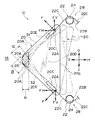
図2,図3に示されるように、車両用カップホルダ10の隔壁18内には、略三角形状の支持部材20が対称に一対配設されている。図5に示されるように、各々の支持部材20は、支持機構28によってホルダ本体部12に対して容器14の挿入及び取出し方向の双方向(矢印I方向及び矢印O方向)に所定の揺動角α,βの範囲内で揺動可能に弾性的に支持されている。
As shown in FIGS. 2 and 3, a pair of substantially
支持部材20は、容器14を挿入していない中立状態において隔壁18の窓18Aから容器収容部16側に最も突出した頂上部20Aを有すると共に、該頂上部20Aから上下方向両側に向かうに従って容器収容部16への突出量が夫々漸減するような第1支持面31及び第2支持面32を有している。支持部材20において、第1支持面31は、主として容器挿入時に容器側面を支持する部分であり、頂上部20Aよりも上側の上部20E側に形成されている。第2支持面32は、主として容器取出し時に容器側面を支持する部分であり、頂上部20Aよりも下側の下部20F側に形成されている。頂上部20Aは、例えば第1支持部31及び第2支持部32に連続した曲面に形成されている。なお、隔壁18の窓18Aの高さは、支持部材20の底辺20Gの長さよりも小さく形成され、支持部材20が窓18Aから飛び出すことがないように構成されている。
The
支持部材20の上部20E及び下部20Fは、ねじりコイルばね22(弾性体)によって夫々容器収容部16側へ付勢されている。具体的には、支持部材20の側面20Dには、支持部材20が付勢されている容器収容部16側への方向(矢印S方向)に対して交差する方向、例えば第1支持面31及び第2支持面32に沿って、スリット状のガイド部20Cが設けられ、図4に示されるように、ねじりコイルばね22の端部22Aは、例えばL字形に折り曲げられてガイド部20C内に差し込まれ、該端部22Aが摩擦力を伴いつつガイド部20Cに対して摺動可能となっている。
The
ここで、ガイド部20Cの方向を、支持部材20が付勢されている容器収容部側への方向(矢印S方向)に対して交差する方向としているのは、ガイド部20Cの長手方向が支持部材20の付勢方向と平行であると、支持部材20がねじりコイルばね22の付勢力にほとんど妨げられることなく矢印S方向及び矢印H方向に動くことができてしまうため、容器14に対する保持力が不十分となるからである。
Here, the direction of the
図2から図4に示されるように、支持機構28は、例えば、壁18内の上下に設けられた支持軸24と、該支持軸24にコイル部22Bを通すことで取り付けられたねじりコイルばね22とを有しており、該ねじりコイルばね22の端部22Aは、一対の支持部材20のガイド部20Cに夫々差し込まれて、該一対の支持部材20を付勢するために共用されている。また、コイル部22Bから接線状に延びる直線部22Cは、組立て状態(中立状態)においてガイド部20Cの長手方向と略平行となっており、付勢力Fはガイド部20Cの長手方向と略直角方向に作用している。
As shown in FIGS. 2 to 4, the
この付勢力Fの水平方向成分FHにより、支持部材20は容器収容部16に突出する方向(矢印S方向)に付勢されている。一方、付勢力Fの垂直方向成分FVは上下のねじりコイルばね22間で互いに逆方向に作用してバランスしている。このようにして、支持部材20は、容器14の出し入れ方向における中立位置に保持されている。なお、ガイド部20Cは、溝状のものに限られず、ねじりコイルばね22の端部22Aを案内できるものであれば側面20Dから突出していてもよい。また、ねじりコイルばね22の取付け状態についても、図示のものには限られない。ねじりコイルばね22の代わりに、板ばねや圧縮コイルばね、その他の弾性体を用いてもよい。
Due to the horizontal component FH of the biasing force F, the
上記のように、車両用カップホルダ10では、支持機構28が、容器14の挿入時には、支持部材20の第2支持面32が容器側面から離間して第1支持面31が該容器側面に弾性的に圧接されるように支持部材20を揺動させ、容器14の取出し時には、支持部材20の第1支持面31が容器側面から離間して第2支持面32が該容器側面に弾性的に圧接されるように支持部材20を揺動させるようになっている。
As described above, in the
また、支持部材20を付勢するねじりコイルばね22の端部22Aが、支持部材20のガイド部20Cに対して摺動可能に取り付けられているので、支持部材20の揺動角α,βが大きくなっており、これによって頂上部20Aが容器14の形状により広い範囲で追従可能に構成されている。
Further, since the
(作用)
まず、支持部材20の基本的な作用について説明すると、図5において、車両用カップホルダ10では、支持部材20が揺動角α,βの範囲内で矢印I方向及び矢印O方向(容器の出し入れ方向)に弾性的に揺動可能であり、かつ矢印H方向に弾性的に最大で距離Bだけ後退可能である(矢印S方向及び矢印H方向に距離Bのストロークを有している)ので、支持部材20の頂上部20Aの可動範囲26は、例えば図示のようになる。
(Function)
First, the basic operation of the
支持部材20は、中立状態では支持機構28における上下のねじりコイルばね22により付勢されて、頂上部20Aが傾くことなく収納部16へ矢印S方向に突出しており、上側のねじりコイルばね22の端部22Aは上側のガイド部20Cの上端に位置し、下側のねじりコイルばね22の端部22Aは下側のガイド部20Cの下端に位置している。支持部材20に、ねじりコイルばね22の付勢力を上回る矢印H方向(水平方向)の外力が作用した場合、該支持部材20は矢印H方向に最大で距離Bだけ弾性的に後退する。
The
支持部材20が後退した状態で、更に頂上部20A付近にねじりコイルばね22の付勢力を上回る矢印I方向(容器の挿入方向)の外力が作用した場合、該支持部材20は矢印I方向に最大で角度βだけ弾性的に傾くことができ、また、逆に矢印O方向に外力が作用した場合には、該支持部材20は矢印O方向に最大で角度αだけ弾性的に傾くことができる。支持部材20が後退していない状態でも、該支持部材20は矢印O方向及び矢印I方向に弾性的に揺動することができる。
In the state in which the
支持部材20がこのように動いた場合における頂上部20Aの軌跡が、可動範囲26となる。なお、図示の可動範囲26は、一例を示したものに過ぎず、ねじりコイルばね22の直線部22Cの長さや、ねじりコイルばね22の取付け方、ガイド部20Cの長さ等を変えることによって角度α,βや可動範囲26を調整することができる。
The trajectory of the top 20A when the
次に、このような支持部材20の動きを踏まえて、容器14を出し入れする際の作用について説明する。まず、図6において、容器14を矢印I方向に挿入すると、該容器14が最初に支持部材20の第1支持面31に当接する。そこから更に容器14を押し込んだ場合、該容器14に対する支持部材20の当接位置が第1支持面31から頂上部20Aへと円滑に移行する。これによって支持部材20が下に傾くようなモーメントが円滑に生ずるので、容器14の挿入性が良好となる。
Next, based on the movement of the
具体的には、上側のねじりコイルばね22の端部22Aは、ガイド部20Cの上側端部に位置しているのでそれ以上該ガイド部20C内を摺動することができず、支持部材20の上部20Eはねじりコイルばね22の付勢力に妨げられてあまり動かない(上部20Eの動きは、直線部22Cの長さやばね定数等の設定により異なる。)。
Specifically, since the
しかし、下側のねじりコイルばね22の端部22Aは、ガイド部20Cの下側端部に位置しており、該ガイド部20C内を摺動する余地があるので、支持部材20の下部20Fは上側のねじりコイルばね22の端部22A付近を中心として矢印I方向(下向き)に傾くことになる。支持部材20が下向きに傾いて行くと、頂上部20Aが矢印H方向に次第に後退して(容器収容部16内への突出量が減少して)行くので、該容器14を容器収容部16の底まで挿入することができる。
However, the
このとき、下側のねじりコイルばね22の端部22Aがガイド部20Cの上側端部に至るまでは付勢力があまり増加しないので軽い力で容器14を挿入することができる。また、端部22Aがガイド部20Cの上側端部に至ったところから更に容器14を挿入すると、今度は下側のねじりコイルばね22の変形を伴うため付勢力が増加する。この状態で挿入を完了すれば、容器14は高い保持力のままで保持される。
At this time, since the urging force does not increase so much until the
容器14の保持状態においては、支持部材20の頂上部20A付近は、ねじりコイルばね22の付勢力によって容器14の側部14Bに弾性的に接触しているので、該容器14は該ねじりコイルばね22の付勢力によって良好に保持される。容器14を保持する支持部材20の状態は、該容器14の大きさや表面性状により異なり、図7の二点鎖線で示されるように、支持部材20が矢印I方向に傾いていたり、同図の実線で示されるように、支持部材20が傾かずに矢印H方向に後退していたりする場合もある。
In the holding state of the
図8に示されるように、容器14の低い位置にくびれ部14A(最適保持位置)がある場合には、挿入の過程で頂上部20Aがねじりコイルばね22の付勢力により該くびれ部14Aに入り込む。容器14の挿入完了状態において、くびれ部14Aが頂上部20Aの可動範囲26にあれば、支持部材20はそのまま該くびれ部14Aを保持した状態となるので、容器14はより安定的に保持される。また、図9に示されるように、上記の場合よりもやや高い位置にくびれ部14Aがある場合でも、該くびれ部14Aが頂上部20Aの可動範囲26にあれば、支持部材20は該くびれ部14Aを保持した状態となる。
As shown in FIG. 8, when there is a
次に、容器14を取り出す際の作用について説明する。図10において、容器14を矢印O方向に取り出そうとした場合、支持部材20はねじりコイルばね22により容器14に押し当てられているので、支持部材20に対して挿入時とは逆方向のモーメントが生じ、支持部材20は容器14の動きに追従するように矢印O方向に傾く。この際、支持部材20における容器14との当接位置は、頂上部20Aから第2支持面32に移行して行く。
Next, the operation when the
またこのとき、下側のねじりコイルばね22の端部22Aは、ガイド部20Cの下側端部に位置しているのでそれ以上該ガイド部20C内を摺動することができず、支持部材20の下部20Fはねじりコイルばね22の付勢力に妨げられてあまり動かない(下部20Fの動きは、直線部22Cの長さやばね定数等の設定により異なる。)。
At this time, the
しかし、上側のねじりコイルばね22の端部22Aは、ガイド部20Cの上側端部に位置しており、該ガイド部20C内を摺動する余地があるので、支持部材20の上部20Eは下側のねじりコイルばね22の端部22A付近を中心として矢印O方向(上向き)に傾くことになる。支持部材20が上向きに傾いて行くと、頂上部20Aが矢印H方向に次第に後退して(容器収容部16内への突出量が減少して)行くので、支持部材20による保持力が弱まり、容器14を円滑に取り出すことができる。容器14が支持部材20から離れると、該支持部材20は中立状態(図1,図2)に復帰する。
However, the
なお、このときの支持部材20の動きは、上記のものに限られず、容器14の取出し前における、上下のガイド部20C内の各々のねじりコイルばね22の端部22Aの位置によって異なる。基本的には、夫々摺動可能な余地があれば、支持部材20はその余地の分だけ矢印O方向に速やかに傾くが、ねじりコイルばね22の端部22Aが各々のガイド部20Cの端部まで至って摺動余地がなくなっていれば、該ねじりコイルばね22の付勢力に抗しながら矢印O方向に傾くことになる。
Note that the movement of the
上記のように、本実施形態に係る車両用カップホルダ10では、容器収容部16内に突出した頂上部20Aを有する支持部材20が容器14を弾性的に保持可能に構成されているだけでなく、容器14の出し入れ方向に弾性的に揺動可能に構成されているので、容器14の挿入時には支持部材20がその挿入方向に傾き、容器14の取出し時にはその取出し方向に傾くことができる。このため、車両用カップホルダ10は、容器14の挿入性及び取出し性に優れている。特に、支持部材20のうち頂上部20Aよりも上部20E及び下部20Fが夫々ねじりコイルばね22により容器収容部16側へ付勢され、支持部材20の頂上部20Aが柔軟な可動範囲26を有しているため、容器14の挿入性及び取出しに優れている。
As described above, in the
また、車両用カップホルダ10では、ねじりコイルばね22の端部22Aが、第1支持面31及び第2支持面32に沿って設けられたガイド部20Cに対して摺動可能であり、支持部材20に対して固定はされていないので、支持部材20の揺動角α,β(頂上部20Aの可動範囲26)がより広くなっており、支持部材20(特に頂上部20A)が容器14の形状に追従し易い。従って、容器14の最適保持位置が高さ方向に異なっていても、その位置が頂上部20Aの可動範囲26であればその位置で該容器14を保持することができるので、多種類の容器14を安定的に保持することが可能である。
In the
更に、支持部材20の容器収容部16側の頂上は頂上部20Aであり、第1支持面31及び第2支持面32の突出量は頂上部20Aから上下方向に離れるに従って漸減しているので、容器14の出し入れの際に支持部材20が傾いたときでも、第1支持面31及び第2支持面32が容器14の出し入れを妨げることはなく、挿入性及び取出し性が良好である。
Further, the top of the
更に、支持部材20は、ガイド部20Cの範囲内ではねじりコイルばね22の付勢力にあまり妨げられずに容易に揺動することができるため、容器14の出し入れ時に支持部材20の向きが変わり易く、挿入性及び取出し性が一層良好となる。
Furthermore, since the
そして、車両用カップホルダ10では、並列に設けられた2箇所の容器収容部16間の隔壁18に支持部材20が対称に一対配設され、ねじりコイルばね22が該一対の支持部材20に共用されるので、2箇所の容器収容部16を有し、容器14の挿入性、取出し性及び保持性に優れた車両用カップホルダ10を低コストで提供することができる。
In the
10 車両用カップホルダ
12 ホルダ本体部
14 容器
16 容器収容部
18 隔壁
20 支持部材
20C ガイド部
22 ねじりコイルばね(弾性体)
22A 端部
28 支持機構
31 第1支持面
32 第2支持面
DESCRIPTION OF
Claims (4)
該支持部材を支持するホルダ本体部と、
該ホルダ本体部に対して支持部材を前記容器の挿入及び取出し方向の双方向に所定の揺動角の範囲内で揺動可能に弾性的に支持し、前記容器の挿入時には、前記支持部材の第2支持面が前記容器側面から離間して第1支持面が該容器側面に弾性的に圧接されるように前記支持部材を揺動させ、前記容器の取出し時には、前記支持部材の第1支持面が前記容器側面から離間して第2支持面が該容器側面に弾性的に圧接されるように前記支持部材を揺動させる支持機構と、
を有することを特徴とする車両用カップホルダ。 The container is provided with a first support surface that is provided in a protruding state into a container accommodating portion capable of accommodating the container, and that mainly supports the side surface of the container when the container is inserted, and a second support surface that mainly supports the side surface of the container when the container is removed. And a support member provided in the take-out direction;
A holder main body for supporting the support member;
A support member is elastically supported with respect to the holder main body so as to be swingable within a range of a predetermined swing angle in both the insertion and removal directions of the container, and when the container is inserted, The support member is swung so that the second support surface is separated from the container side surface and the first support surface is elastically pressed against the container side surface, and the first support of the support member is taken out when the container is taken out. A support mechanism for swinging the support member such that the surface is spaced apart from the container side surface and the second support surface is elastically pressed against the container side surface;
A vehicle cup holder characterized by comprising:
前記弾性体の端部は、該ガイド部に対して摺動可能に取り付けられていることを特徴とする請求項2に記載の車両用カップホルダ。 The support member has a guide portion extending along a direction intersecting the direction toward the container housing portion on which the support member is biased,
The vehicle cup holder according to claim 2, wherein an end of the elastic body is slidably attached to the guide portion.
Priority Applications (1)
| Application Number | Priority Date | Filing Date | Title |
|---|---|---|---|
| JP2005278755A JP2007084022A (en) | 2005-09-26 | 2005-09-26 | Vehicle cup holder |
Applications Claiming Priority (1)
| Application Number | Priority Date | Filing Date | Title |
|---|---|---|---|
| JP2005278755A JP2007084022A (en) | 2005-09-26 | 2005-09-26 | Vehicle cup holder |
Publications (1)
| Publication Number | Publication Date |
|---|---|
| JP2007084022A true JP2007084022A (en) | 2007-04-05 |
Family
ID=37971448
Family Applications (1)
| Application Number | Title | Priority Date | Filing Date |
|---|---|---|---|
| JP2005278755A Pending JP2007084022A (en) | 2005-09-26 | 2005-09-26 | Vehicle cup holder |
Country Status (1)
| Country | Link |
|---|---|
| JP (1) | JP2007084022A (en) |
Cited By (2)
| Publication number | Priority date | Publication date | Assignee | Title |
|---|---|---|---|---|
| WO2010113980A1 (en) * | 2009-04-01 | 2010-10-07 | 株式会社ニフコ | Diameter acceptance mechanism for cup holders, and cup holder using same |
| EP2011686B1 (en) * | 2007-07-02 | 2016-08-24 | Calsonic Kansei Corporation | Container securing device |
-
2005
- 2005-09-26 JP JP2005278755A patent/JP2007084022A/en active Pending
Cited By (5)
| Publication number | Priority date | Publication date | Assignee | Title |
|---|---|---|---|---|
| EP2011686B1 (en) * | 2007-07-02 | 2016-08-24 | Calsonic Kansei Corporation | Container securing device |
| WO2010113980A1 (en) * | 2009-04-01 | 2010-10-07 | 株式会社ニフコ | Diameter acceptance mechanism for cup holders, and cup holder using same |
| JP2010241181A (en) * | 2009-04-01 | 2010-10-28 | Nifco Inc | Diameter acceptance mechanism for cup holders, and cup holder using the same |
| CN102378705A (en) * | 2009-04-01 | 2012-03-14 | 株式会社利富高 | Diameter acceptance mechanism for cup holders, and cup holder using same |
| US8807504B2 (en) | 2009-04-01 | 2014-08-19 | Nifco Inc. | Diameter acceptance mechanism for cup holder and cup holder using the same |
Similar Documents
| Publication | Publication Date | Title |
|---|---|---|
| US8353495B2 (en) | Cup holder | |
| US7380762B2 (en) | Container holder of a vehicle | |
| US8898850B2 (en) | Wiper blade | |
| KR100569342B1 (en) | Cup holder support structure for automobile | |
| KR100837086B1 (en) | Car Cup Holder | |
| US8757571B2 (en) | Cup holder | |
| KR101054620B1 (en) | Diameter Tolerance for Cup Holders and Cup Holders Using the Same | |
| US20070278372A1 (en) | Cup holder | |
| US20060043249A1 (en) | Cup holder for vehicles | |
| KR100600132B1 (en) | Cup holder support structure for automobile | |
| JP2006001428A (en) | Container holding unit and cup holder device | |
| CN109982895A (en) | Car-mounted electronic device mounting structure | |
| KR20070061424A (en) | A binding tool for documents | |
| KR101276017B1 (en) | Container holding device | |
| JP2007084022A (en) | Vehicle cup holder | |
| US7320493B2 (en) | Sun visor | |
| JP2010195186A (en) | Cup holder | |
| JP2007320493A (en) | Cup holder | |
| JP6031185B2 (en) | Vehicle seat | |
| US6702243B2 (en) | Cup holder for a vehicle | |
| KR100969054B1 (en) | Car Cup Holder | |
| JP2968490B2 (en) | Vehicle cup holder | |
| JP4181407B2 (en) | Liquid level sensor | |
| JPH1095266A (en) | Drink container holding device | |
| KR100786897B1 (en) | Vehicle pen holder |