JP2007073816A - Duct type cooling structure - Google Patents
Duct type cooling structure Download PDFInfo
- Publication number
- JP2007073816A JP2007073816A JP2005260632A JP2005260632A JP2007073816A JP 2007073816 A JP2007073816 A JP 2007073816A JP 2005260632 A JP2005260632 A JP 2005260632A JP 2005260632 A JP2005260632 A JP 2005260632A JP 2007073816 A JP2007073816 A JP 2007073816A
- Authority
- JP
- Japan
- Prior art keywords
- cooling
- heating element
- fin
- protrusion
- duct type
- Prior art date
- Legal status (The legal status is an assumption and is not a legal conclusion. Google has not performed a legal analysis and makes no representation as to the accuracy of the status listed.)
- Withdrawn
Links
Images


Landscapes
- Cooling Or The Like Of Electrical Apparatus (AREA)
- Cooling Or The Like Of Semiconductors Or Solid State Devices (AREA)
Abstract
Description
本発明は冷媒を流す筒状筐体の外面に発熱体を有するダクト型冷却構造に関する。 The present invention relates to a duct type cooling structure having a heating element on the outer surface of a cylindrical casing through which a refrigerant flows.
従来のダクト型冷却構造においては、矩形の筒状筐体の外側の一面に発熱体が接触していて、筒状筐体の発熱体に対応する内側の面に等間隔に放熱板が配置されている。 In a conventional duct type cooling structure, a heating element is in contact with one outer surface of a rectangular cylindrical casing, and heat radiating plates are arranged at equal intervals on the inner surface corresponding to the heating element of the cylindrical casing. ing.
しかし、上記のような従来の構造では、放熱板の全ての部分が有効に放熱に寄与していることはなく、放熱板の発熱体から遠い部分は冷媒との温度差が少なくなり、放熱板として機能していない領域がある。 However, in the conventional structure as described above, not all portions of the heat sink effectively contribute to heat dissipation, and the portion far from the heating element of the heat sink reduces the temperature difference with the refrigerant, and the heat sink There are areas that are not functioning.
本発明は上記のような問題を解決するためになされたもので、軽量なダクト型冷却構造を提供することを目的としている。 The present invention has been made to solve the above-described problems, and an object thereof is to provide a lightweight duct-type cooling structure.
この目的を達成するため、本発明においては、冷却突起は、冷媒流に沿って少なくとも発熱体より上流側では、上流側ほど背が低くなっている。 In order to achieve this object, in the present invention, the cooling protrusion is shorter at the upstream side at least upstream of the heating element along the refrigerant flow.
本発明によれば、冷却能力を落とさず、ダクト型冷却構造全体の重量を軽減することができる。 According to the present invention, it is possible to reduce the weight of the entire duct type cooling structure without reducing the cooling capacity.
(第1の実施の形態)
図1は本発明の第1の実施の形態を説明する図、図2は図1の線分A−Aで切った断面図である。図に示すように、冷媒の流れに直角な断面形状が矩形の筒状筐体2の外側の一面に発熱体3が接触して取り付けられている。また、筒状筐体2の発熱体3に対応する内側の面に等間隔にフィン状冷却突起(板状冷却突起、放熱板、冷却板とも呼ばれるが、同じものである)1が配置され、フィン状冷却突起1は冷媒流に沿って少なくとも発熱体3より上流側では、上流側ほど背が低くなっている。従来のダクト型冷却構造においては、フィン状冷却突起の背は均一であるが、本発明では発熱体3より上流にあって冷却効果があまり期待できないフィン状冷却突起1の部位を削り、背を低くした。これによって、ダクト型冷却構造が軽量となる。
(First embodiment)
FIG. 1 is a diagram for explaining a first embodiment of the present invention, and FIG. 2 is a cross-sectional view taken along line AA in FIG. As shown in the figure, a
なお、図1、図2では、フィン状冷却突起1は筒状筐体2の発熱体3のある面から生えて、筒状筐体2の対向する面に達している。しかし、これは本質的ではなく、フィン状冷却突起が対向する面に達していても、いなくてもよい。
In FIGS. 1 and 2, the fin-
また、これだけではフィン状冷却突起1を削除した分、発熱体3から遠い側すなわち図1紙面上側ほど冷媒の摩擦抵抗が小さくなり、発熱体3から遠い側の冷媒の速度が大きくなり、結果的に発熱体3に近い側の冷媒の速度が小さくなってしまう傾向が気になる場合には、たとえば図3、図4に示すような構造をとる。図3は図2の線分B−Bで切り、上から見下ろした断面図に相当し、図3中の斜線部は切り口を示す。また、図4は図1と同様の正面図である。図に示すように、フィン状冷却突起1の冷媒流下流側の端部に冷媒流に対して直角方向に突出した副突起11が設けられている。これはすなわち、フィン状冷却突起1に発熱体3から遠ざかるに従って冷媒流の摩擦を増やす働きをしている。このため、発熱体3から遠い側の摩擦抵抗を補償することができ、フィン全体に対して冷却速度を均一にできる。
In addition, only the amount of the fin-
なお、図4に示す副突起11の形状は三角形状に描かれているが、実際にはフィン状冷却突起1と冷媒との熱伝達率、温度差、筒状筐体2やフィン状冷却突起1の寸法などを加味し、シミュレーションにより副突起の形状が決定される。
Although the shape of the
図5は別の実施の形態を示す横断面図(図2と同様の断面図)である。図に示すように、筒状筐体2の発熱体3に対応する内側の面に等間隔にフィン状冷却突起4が配置され、フィン状冷却突起4は冷媒流に沿って少なくとも発熱体3より上流側では、上流側ほど段階的に背が低くなっている。また、フィン状冷却突起4の冷媒流上流側の端部に冷媒流に対して直角方向に突出した副突起12が取り付けられている。ここで、図示はしないが複数に別れた副突起12の形状は段階的に図5紙面直角方向の大きさが変化し、発熱体3から遠い側すなわち図5紙面上側ほど副突起12は横に大きく張り出している。すなわち、フィン状冷却突起4に発熱体3から遠ざかるに従って冷媒流の摩擦を増やす副突起12が設けられている。
FIG. 5 is a cross-sectional view (cross-sectional view similar to FIG. 2) showing another embodiment. As shown in the figure, fin-
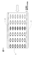
また、図6(図2と同様の断面図)、図7(図6の線分C−Cで切った断面図)、図8(正面図)は別の実施の形態を示す図である。図に示すように、筒状筐体2の発熱体3に対応する内側の面に等間隔にフィン状冷却突起5が配置され、フィン状冷却突起5は冷媒流に沿って少なくとも発熱体3より上流側では、上流側ほど背が低くなっている。また、フィン状冷却突起5は波打っている。また、図8中の斜線部は波打ったフィン状冷却突起5の投影断面であり、発熱体3から遠い側ほどフィン状冷却突起5は大きく波打っている。すなわち、フィン状冷却突起5は冷媒の流れを妨げる方向に波打っており、その振幅は根本から先端へ進むに従って大きくなっており、フィン状冷却突起5の冷媒流に沿って見たときの投影断面形状の幅が根本付近より先端付近の方が大きくなっている。このため、発熱体3から遠い側の冷媒の摩擦抵抗を増やすことができるから、発熱体3に近い側の冷媒の速度が大きくなるので、冷却効率が向上する。
FIG. 6 (cross-sectional view similar to FIG. 2), FIG. 7 (cross-sectional view taken along line CC in FIG. 6), and FIG. 8 (front view) are views showing another embodiment. As shown in the figure, fin-
(第2の実施の形態)
図9は本発明の第2の実施の形態を説明する横断面図、図10は図9の線分D−Dで切った断面図である。図に示すように、筒状筐体2の発熱体3に対応する内側の面に等間隔に矩形柱状冷却突起(複数に分割されたフィン状冷却突起)6が配置され、矩形柱状冷却突起6は冷媒流に沿って少なくとも発熱体3より上流側では、上流側ほど背が低くなっている。また、矩形柱状冷却突起6の先端に冷媒流に対して直角方向に突出した副突起13が付けられている。なお、図10の斜線部は矩形柱状冷却突起6を切った断面、実線は図9の線分D−Dより低い矩形柱状冷却突起6の上面を示し、破線は図9の線分D−Dよりも背が高い矩形柱状冷却突起6の副突起13の形状を暗示している。また、冷媒流下流側ほどに副突起13の横への張出量を大きくしてある。
(Second Embodiment)
FIG. 9 is a transverse sectional view for explaining a second embodiment of the present invention, and FIG. 10 is a sectional view taken along line DD in FIG. As shown in the figure, rectangular columnar cooling protrusions (fin-shaped cooling protrusions divided into a plurality of parts) 6 are arranged at equal intervals on the inner surface corresponding to the
このダクト型冷却構造においては、矩形柱状冷却突起6は冷媒流に沿って少なくとも発熱体3より上流側では、上流側ほど背が低くなっているから、ダクト型冷却構造が軽量となる。また、各矩形柱状冷却突起6の冷媒流方向の間に間隙があるから、冷媒の流れが乱れて冷却効率が高まる。また、矩形柱状冷却突起6の先端に副突起13が付けられているから、発熱体3に近い側の冷媒の速度が大きくなるので、冷却効率が向上する。
In this duct type cooling structure, the rectangular
図11は別の実施の形態を示す断面図(図10と同様の断面図)、図12は図11に示した実施の形態の楕円柱状冷却突起を示す斜視図である。図に示すように、筒状筐体2の発熱体3に対応する内側の面に等間隔に楕円柱状冷却突起7が配置され、楕円柱状冷却突起7は冷媒流に沿って少なくとも発熱体3より上流側では、上流側ほど背が低くなっている。また、楕円柱状冷却突起7は楕円柱状をなし、発熱体3に近い根本の方は冷媒の流れにそって細長く、先端へゆくに従って、冷媒の流れを妨げるように幅が太くなっている。すなわち、図11中の矢印の方向から眺めた投影断面図は前記図8と同等であり、楕円柱状冷却突起7の冷媒流に沿って見たときの投影断面形状の幅が根本付近より先端付近の方が大きい。なお、図11中の斜線部、破線部の意味は図10と同じである。また、楕円柱状冷却突起7は、内部まで導体が存在してもよく、あるいは中空であってもよい。
11 is a cross-sectional view showing another embodiment (a cross-sectional view similar to FIG. 10), and FIG. 12 is a perspective view showing an elliptic columnar cooling protrusion of the embodiment shown in FIG. As shown in the figure, elliptical
図13はさらに別の実施の形態を示す断面図(図10と同様の断面図)、図14は図13に示した実施の形態に矩形柱状冷却突起を示す斜視図である。図に示すように、筒状筐体2の発熱体3に対応する内側の面に等間隔に矩形柱状冷却突起(複数に分割されたフィン状冷却突起)8が配置され、矩形柱状冷却突起8は冷媒流に沿って少なくとも発熱体3より上流側では、上流側ほど背が低くなっている。また、矩形柱状冷却突起8は先端へゆくに従ってねじれて、冷媒の流れを妨げるようになっている。すなわち、図13中の矢印の方向から眺めた投影断面図は図8と同等であり、矩形柱状冷却突起8の冷媒流に沿って見たときの投影断面形状の幅が根本付近より先端付近の方が大きい。なお、フィン状冷却突起8の板を捻る方向は互い違いにしたが、フィン状冷却突起8の板を捻る方向は任意である。
13 is a cross-sectional view showing another embodiment (a cross-sectional view similar to FIG. 10), and FIG. 14 is a perspective view showing a rectangular columnar cooling protrusion in the embodiment shown in FIG. As shown in the figure, rectangular columnar cooling protrusions (fin-shaped cooling protrusions divided into a plurality of parts) 8 are arranged at equal intervals on the inner surface corresponding to the
(第3の実施の形態)
図15は本発明の第3の実施の形態を説明する正面図であり、図15は図1と同様の正面図であり、図15の線分E−Eで切った断面図は図2と同等である。図に示すように、筒状筐体21の図15紙面上部の寸法が図15紙面下部の寸法よりも小さくなっている。また、筒状筐体21の外側の一面に発熱体3が接触して取り付けられていて、筒状筐体21の発熱体3に対応する内側の面に等間隔にフィン状冷却突起22が配置され、フィン状冷却突起22は冷媒流に沿って少なくとも発熱体3より上流側では、上流側ほど背が低くなっており、フィン状冷却突起22によって区切られた通路の図15紙面上部の寸法が図15紙面下部の寸法よりも小さくなっている。すなわち、筒状筐体21の冷媒の流れに直角な断面形状が台形をなし、フィン状冷却突起22は先端へゆくほど互いの間隔が狭くなるように配置されている。
(Third embodiment)
15 is a front view for explaining a third embodiment of the present invention, FIG. 15 is a front view similar to FIG. 1, and a cross-sectional view taken along line E-E in FIG. It is equivalent. As shown in the drawing, the dimension of the upper part of the sheet of the
このダクト型冷却構造においては、フィン状冷却突起22は冷媒流に沿って少なくとも発熱体3より上流側では、上流側ほど背が低くなっているから、ダクト型冷却構造が軽量となる。また、発熱体3から遠い側すなわち図15紙面上部は、フィン状冷却突起22が少ない分、そのままでは摩擦抵抗が小さくなって、冷却効率が低い部分に冷媒が多く流れてしまうことになるが、図15に示すように発熱体3から遠い側の通路すなわち図15紙面上部の通路を狭めているから、発熱体3に近い側の冷媒の速度が大きくなるので、冷却効率を維持することができ、さらに筒状筐体21全体の重量を軽減することができる。
In this duct-type cooling structure, the fin-shaped
(第4の実施の形態)
図16は本発明の第4の実施の形態を説明する横断面図であり、図16は図2と同様の断面図である。図に示すように、筒状筐体2の発熱体3に対応する内側の面に等間隔にフィン状冷却突起31が配置され、フィン状冷却突起31に丸穴32が設けられて(穿たれて)おり、丸穴32は冷媒流に沿って少なくとも発熱体3より上流側では、上流側ほど筒状筐体2の発熱体3が取り付けられた面の近くまで設けられている。すなわち、フィン状冷却突起31中の冷却効率の低い領域を図2のように切り取る代わりに、丸穴32をあけてある。
(Fourth embodiment)
FIG. 16 is a transverse sectional view for explaining a fourth embodiment of the present invention, and FIG. 16 is a sectional view similar to FIG. As shown in the figure, fin-
このダクト型冷却構造においては、フィン状冷却突起31に丸穴32が設けられているから、ダクト型冷却構造が軽量となる。また、従来のダクト型冷却構造の放熱板の発熱体3より上流側の上部の温度と冷媒の温度との温度差は小さいから、丸穴32を冷媒流に沿って少なくとも発熱体3より上流側では、上流側ほど筒状筐体2の発熱体3が取り付けられた面の近くまで設けたとしても、冷却効率が低下することはない。また、フィン状冷却突起31を筒状筐体2の2つの面で固定することができるので、ダクト型冷却構造の強度が増す。また、丸穴32を設けることで副突起と同様に発熱体3から遠い側の摩擦抵抗を補償することができ、発熱体3に近い側の冷媒の速度が大きくなるから、冷却効率が向上する。
In this duct type cooling structure, since the round holes 32 are provided in the fin-
図17は別の実施の形態を説明する横断面図、図18は図17の線分F−Fで切った断面図である。図に示すように、筒状筐体2の発熱体3に対応する内側の面に等間隔にフィン状冷却突起41が配置され、フィン状冷却突起41に四角い穴42が設けられており、四角い穴42は冷媒流に沿って少なくとも発熱体3より上流側では、上流側ほど筒状筐体2の発熱体3が取り付けられた面の近くまで設けられている。すなわち、図16では丸穴32を空けたが、ここでは四角い穴42を設け、格子のように残ったフィン状冷却突起41の部分を捻って副突起と同等の機能をもたせてある。すなわち、四角い穴42穴同士の間のフィン状冷却突起41の一部が捻られている。
FIG. 17 is a cross-sectional view illustrating another embodiment, and FIG. 18 is a cross-sectional view taken along line FF in FIG. As shown in the figure, fin-
図19はさらに別の実施の形態を説明する横断面図、図20は図19の線分G−Gで切った断面図である。図に示すように、筒状筐体2の発熱体3に対応する内側の面に等間隔にフィン状冷却突起51が配置され、フィン状冷却突起51に四角い穴52が設けられており、四角い穴52は冷媒流に沿って少なくとも発熱体3より上流側では、上流側ほど筒状筐体2の発熱体3が取り付けられた面の近くまで設けられている。そして、四角い穴52を設けるためにフィン状冷却突起51を切り取る部分を少し残し、その残した部分を折り曲げて副突起53としている。すなわち、四角い穴52の縁に副突起53が設けられている。なお、本実施の形態では、フィン状冷却突起51の切り取る部分を残した部分を折り曲げる方向を互い違いにしたが、折り曲げる方向は任意である。
FIG. 19 is a cross-sectional view illustrating still another embodiment, and FIG. 20 is a cross-sectional view taken along the line GG in FIG. As shown in the figure, fin-
1…フィン状冷却突起 2…筒状筐体
3…発熱体 4…フィン状冷却突起
5…フィン状冷却突起 6…矩形柱状冷却突起
7…楕円柱状冷却突起 8…矩形柱状冷却突起
11…副突起 12…副突起
13…副突起 21…筒状筐体
22…フィン状冷却突起 31…フィン状冷却突起
32…丸穴 41…フィン状冷却突起
42…四角い穴 51…フィン状冷却突起
52…四角い穴 53…副突起
DESCRIPTION OF
Claims (9)
前記発熱体に対応する前記筒状筐体の内面に冷却突起を有し、
前記冷却突起は、前記冷媒流に沿って少なくとも前記発熱体より上流側では、上流側ほど背が低くなっている、
ことを特徴とする、ダクト型冷却構造。 A heating element is provided on the outer surface of the cylindrical casing through which the refrigerant flows,
A cooling protrusion on the inner surface of the cylindrical housing corresponding to the heating element;
The cooling protrusion has a shorter height toward the upstream side at least upstream from the heating element along the refrigerant flow.
A duct type cooling structure characterized by that.
ことを特徴とする、前記請求項1に記載のダクト型冷却構造。 The cooling protrusion is a fin-shaped cooling protrusion or a columnar cooling protrusion,
The duct type cooling structure according to claim 1, wherein:
ことを特徴とする、前記請求項1または2に記載のダクト型冷却構造。 The cooling protrusion has a sub-projection that increases the friction of the refrigerant flow as the distance from the heating element increases.
The duct type cooling structure according to claim 1 or 2, wherein
ことを特徴とする、前記請求項1または2に記載のダクト型冷却構造。 The width of the projected cross-sectional shape of the cooling protrusion when viewed along the refrigerant flow is greater near the tip than near the root.
The duct type cooling structure according to claim 1 or 2, wherein
ことを特徴とする、前記請求項2に記載のダクト型冷却構造。 The fin-like cooling protrusions are undulating in a direction that obstructs the flow of the refrigerant, the amplitude of which increases as it proceeds from the root to the tip.
The duct type cooling structure according to claim 2, wherein:
ことを特徴とする、前記請求項1または2に記載のダクト型冷却構造。 The cross-sectional shape perpendicular to the refrigerant flow of the cylindrical housing forms a trapezoid, and the cooling protrusions are arranged so that the distance between them becomes narrower toward the tip.
The duct type cooling structure according to claim 1 or 2, wherein
前記発熱体に対応する前記筒状筐体の内面に対向する面へ至るフィン状冷却突起を設け、
前記フィン状冷却突起には穴が設けられており、
前記穴は、前記冷媒流に沿って少なくとも前記発熱体より上流側では、上流側ほど前記筒状筐体の前記発熱体が取り付けられた面の近くまで設けられている、
ことを特徴とする、ダクト型冷却構造。 A heating element is provided on the outer surface of the cylindrical casing through which the refrigerant flows,
Providing fin-like cooling protrusions that reach the surface facing the inner surface of the cylindrical housing corresponding to the heating element;
A hole is provided in the fin-like cooling protrusion,
The hole is provided along the refrigerant flow at least on the upstream side of the heating element, and closer to the surface to which the heating element of the cylindrical housing is attached toward the upstream side.
A duct type cooling structure characterized by that.
ことを特徴とする、前記請求項7に記載のダクト型冷却構造。 A part of the fin-like cooling protrusion between the holes is twisted,
The duct type cooling structure according to claim 7, characterized in that:
ことを特徴とする、前記請求項7に記載のダクト型冷却構造。 Sub-projections are provided on the edge of the hole,
The duct type cooling structure according to claim 7, characterized in that:
Priority Applications (1)
| Application Number | Priority Date | Filing Date | Title |
|---|---|---|---|
| JP2005260632A JP2007073816A (en) | 2005-09-08 | 2005-09-08 | Duct type cooling structure |
Applications Claiming Priority (1)
| Application Number | Priority Date | Filing Date | Title |
|---|---|---|---|
| JP2005260632A JP2007073816A (en) | 2005-09-08 | 2005-09-08 | Duct type cooling structure |
Publications (1)
| Publication Number | Publication Date |
|---|---|
| JP2007073816A true JP2007073816A (en) | 2007-03-22 |
Family
ID=37934991
Family Applications (1)
| Application Number | Title | Priority Date | Filing Date |
|---|---|---|---|
| JP2005260632A Withdrawn JP2007073816A (en) | 2005-09-08 | 2005-09-08 | Duct type cooling structure |
Country Status (1)
| Country | Link |
|---|---|
| JP (1) | JP2007073816A (en) |
Cited By (5)
| Publication number | Priority date | Publication date | Assignee | Title |
|---|---|---|---|---|
| JP2012119102A (en) * | 2010-11-30 | 2012-06-21 | Hitachi Ltd | Switch unit and switch gear mounting switch unit |
| DE102011079508B4 (en) * | 2010-09-10 | 2013-12-24 | Mitsubishi Electric Corp. | Cooling structure for a semiconductor element |
| CN104335313A (en) * | 2012-05-29 | 2015-02-04 | 株式会社日立制作所 | Switching unit or switching gear |
| JP2016181547A (en) * | 2015-03-23 | 2016-10-13 | 日本電気株式会社 | Heat sink, cooling structure and device |
| WO2019189726A1 (en) * | 2018-03-30 | 2019-10-03 | 古河電気工業株式会社 | Heatsink |
-
2005
- 2005-09-08 JP JP2005260632A patent/JP2007073816A/en not_active Withdrawn
Cited By (11)
| Publication number | Priority date | Publication date | Assignee | Title |
|---|---|---|---|---|
| DE102011079508B4 (en) * | 2010-09-10 | 2013-12-24 | Mitsubishi Electric Corp. | Cooling structure for a semiconductor element |
| JP2012119102A (en) * | 2010-11-30 | 2012-06-21 | Hitachi Ltd | Switch unit and switch gear mounting switch unit |
| CN102543557A (en) * | 2010-11-30 | 2012-07-04 | 株式会社日立制作所 | Switch unit and switchgear equipped therewith |
| EP2458697A3 (en) * | 2010-11-30 | 2014-01-01 | Hitachi Ltd. | Switch unit and switchgear equipped therewith |
| US8872054B2 (en) | 2010-11-30 | 2014-10-28 | Hitachi, Ltd. | Switch unit and switchgear equipped therewith |
| CN104335313A (en) * | 2012-05-29 | 2015-02-04 | 株式会社日立制作所 | Switching unit or switching gear |
| JP2016181547A (en) * | 2015-03-23 | 2016-10-13 | 日本電気株式会社 | Heat sink, cooling structure and device |
| WO2019189726A1 (en) * | 2018-03-30 | 2019-10-03 | 古河電気工業株式会社 | Heatsink |
| TWI710743B (en) * | 2018-03-30 | 2020-11-21 | 日商古河電氣工業股份有限公司 | heat sink |
| JPWO2019189726A1 (en) * | 2018-03-30 | 2021-05-13 | 古河電気工業株式会社 | heatsink |
| JP7328213B2 (en) | 2018-03-30 | 2023-08-16 | 古河電気工業株式会社 | heat sink |
Similar Documents
| Publication | Publication Date | Title |
|---|---|---|
| US7913750B2 (en) | Louvered air center with vortex generating extensions for compact heat exchanger | |
| JP6011481B2 (en) | Heat exchanger fins | |
| CN110849197B (en) | Inner fin of heat exchanger | |
| JP2014020580A (en) | Fin tube type heat exchanger | |
| JP2006064345A (en) | Heat transfer fin | |
| JP5558206B2 (en) | Heat exchanger | |
| US7413002B2 (en) | Corrugated fin and heat exchanger using the same | |
| JP3175160U (en) | heatsink | |
| JP2007073816A (en) | Duct type cooling structure | |
| JP2001174181A (en) | Fin-and-tube heat exchanger and air conditioner equipped with the same | |
| JP2019002588A5 (en) | ||
| JP2004263881A (en) | Heat transfer fin, heat exchanger, evaporator and condenser for car air conditioner | |
| JP2000154987A (en) | Air heat exchanger | |
| CN109268916B (en) | Radiating assembly and electric heating oil heater | |
| JP2009204182A (en) | Heat exchanger | |
| JP6292335B2 (en) | Heat exchanger | |
| JP6559507B2 (en) | Corrugated fin heat exchanger core | |
| JP3957021B2 (en) | Heat exchanger | |
| JP2005079349A (en) | Heatsink having louver | |
| CN106537077B (en) | Heat exchanger core | |
| JP4626422B2 (en) | Finned tube heat exchanger | |
| JP2005140454A (en) | Heat exchanger | |
| JP2523618B2 (en) | Heat exchanger with fins | |
| JP2015001307A (en) | Finned tube heat exchanger | |
| JP2019219139A (en) | Corrugated fin for heat exchanger |
Legal Events
| Date | Code | Title | Description |
|---|---|---|---|
| A621 | Written request for application examination |
Free format text: JAPANESE INTERMEDIATE CODE: A621 Effective date: 20080728 |
|
| A761 | Written withdrawal of application |
Effective date: 20090825 Free format text: JAPANESE INTERMEDIATE CODE: A761 |