JP2007061684A - Standing type crusher - Google Patents
Standing type crusher Download PDFInfo
- Publication number
- JP2007061684A JP2007061684A JP2005247989A JP2005247989A JP2007061684A JP 2007061684 A JP2007061684 A JP 2007061684A JP 2005247989 A JP2005247989 A JP 2005247989A JP 2005247989 A JP2005247989 A JP 2005247989A JP 2007061684 A JP2007061684 A JP 2007061684A
- Authority
- JP
- Japan
- Prior art keywords
- cone
- fin
- recovery
- grinding
- crushing
- Prior art date
- Legal status (The legal status is an assumption and is not a legal conclusion. Google has not performed a legal analysis and makes no representation as to the accuracy of the status listed.)
- Granted
Links
- 238000011084 recovery Methods 0.000 claims abstract description 70
- 239000002245 particle Substances 0.000 claims abstract description 26
- 239000007787 solid Substances 0.000 claims abstract description 10
- 238000000227 grinding Methods 0.000 claims description 54
- 238000010298 pulverizing process Methods 0.000 claims description 44
- 230000002093 peripheral effect Effects 0.000 claims description 10
- 239000003245 coal Substances 0.000 description 31
- 239000011362 coarse particle Substances 0.000 description 13
- 239000000843 powder Substances 0.000 description 12
- 239000010419 fine particle Substances 0.000 description 8
- 230000005514 two-phase flow Effects 0.000 description 7
- 238000010586 diagram Methods 0.000 description 6
- 230000000630 rising effect Effects 0.000 description 5
- 238000012423 maintenance Methods 0.000 description 4
- 238000004519 manufacturing process Methods 0.000 description 4
- 239000000446 fuel Substances 0.000 description 3
- 230000005484 gravity Effects 0.000 description 3
- XEEYBQQBJWHFJM-UHFFFAOYSA-N Iron Chemical compound [Fe] XEEYBQQBJWHFJM-UHFFFAOYSA-N 0.000 description 2
- 230000008901 benefit Effects 0.000 description 2
- 239000003638 chemical reducing agent Substances 0.000 description 2
- 238000003825 pressing Methods 0.000 description 2
- 239000002994 raw material Substances 0.000 description 2
- 230000015556 catabolic process Effects 0.000 description 1
- 238000010276 construction Methods 0.000 description 1
- 238000006731 degradation reaction Methods 0.000 description 1
- 230000006866 deterioration Effects 0.000 description 1
- 238000002474 experimental method Methods 0.000 description 1
- 235000013312 flour Nutrition 0.000 description 1
- 238000009434 installation Methods 0.000 description 1
- 229910052742 iron Inorganic materials 0.000 description 1
- 239000000203 mixture Substances 0.000 description 1
- 230000000149 penetrating effect Effects 0.000 description 1
- 238000010248 power generation Methods 0.000 description 1
- 239000000725 suspension Substances 0.000 description 1
Images


Landscapes
- Crushing And Grinding (AREA)
Abstract
Description
本発明は、粉砕ローラまたは粉砕ボールと粉砕テーブルにより固体原料を粉砕し、分級装置により所定の粒度分布に調整することが可能な竪型粉砕機に係り、特に石炭焚ボイラ装置の微粉炭製造装置として用いるのに好適な竪型粉砕機に関する。 The present invention relates to a vertical pulverizer capable of pulverizing a solid raw material with a pulverizing roller or a pulverizing ball and a pulverizing table and adjusting the particle size distribution to a predetermined particle size distribution with a classifier, and in particular, an apparatus for producing pulverized coal in a coal fired boiler apparatus. The present invention relates to a vertical crusher suitable for use as.
竪型粉砕機は、燃料として微粉炭を燃焼させる火力発電用の石炭焚ボイラプラントにおいて燃料供給装置に使用されている。従来の竪型粉砕機の概略構成例を図9に示す(例えば、特許文献1を参照)。図10は図9に示すX−X線上の断面図、図11は図9に示すY−Y線上の断面図である。この竪型粉砕機は、粉砕テーブル2を回転駆動させる駆動部A、粉砕テーブル2と粉砕ローラ3のかみ込みにより微粉炭の原料である石炭60を粉砕する粉砕部B、粉砕部Bの上部に設置されて微粉炭を任意の粒度に分級する分級部C、及び分級部Cより送られてきた微粉炭をボイラに接続された複数の送炭管31へ分配する分配部Dを主な構成要素としている。
The vertical crusher is used in a fuel supply apparatus in a coal fired boiler plant for thermal power generation in which pulverized coal is burned as fuel. FIG. 9 shows a schematic configuration example of a conventional vertical crusher (see, for example, Patent Document 1). 10 is a cross-sectional view taken along line XX shown in FIG. 9, and FIG. 11 is a cross-sectional view taken along line YY shown in FIG. This vertical pulverizer includes a driving unit A for rotating the pulverizing table 2, a pulverizing unit B for pulverizing
さらに、分級装置の構成要素として回収コーン11が設置されている。回収コーン11は竪型粉砕機の分級装置として、非常に重要な構成要素である。図9に示すように、分級部Cには粉砕部Bから上昇してくる固気二相流62と分級部Cから粉砕部Cへと落下する粗粒子63とが存在する。
Furthermore, the collection |
回収コーン11はこれらの流路を完全に分離するという機能を持つ。すなわち、回収コーン11が無い場合では、分級部Cへと上昇する固気二相流62と粉砕部Bへと落下する粗粒子63の干渉(衝突)が起こり、粗粒子の落下が阻害されたり、落下している粗粒子が固気二相流の上昇流に同伴され再び分級部Cへと送られたりするなどの現象が生じる。特に、竪型粉砕機の処理量が多い高負荷時には、製品微粉の粒度分布の悪化や圧力損失の増大などの性能低下を引き起こす原因となる。このような性能低下を防ぐためにも、回収コーンは必要不可欠の構成要素である。
The
ここで、図9に示す従来の竪型粉砕機の動作について説明する。なお、この動作は後述する本発明の竪型粉砕機のそれと共通している。給炭管1より供給された石炭60は、矢印で示すように粉砕テーブル2の中心部に落下する。粉砕テーブル2は、減速機50を介して駆動モータ51に接続されており、回転駆動している。粉砕テーブル2上に落下した石炭は回転に伴う遠心力によって粉砕テーブル2上を渦巻き状の軌跡を描いて外周部へ移動して、粉砕テーブル2とタイヤ状の粉砕ローラ3との間にかみ込まれて粉砕される。粉砕された石炭は粉砕テーブル2の周囲に設けられたスロート42から導入される熱風61によって、乾燥されながら上方に吹き上げられる。
Here, the operation of the conventional vertical crusher shown in FIG. 9 will be described. This operation is common to that of the vertical crusher of the present invention described later. The
吹き上げられた粉体62のうち、粒度が大きいものは分級部Cへと搬送される途中で重力により落下し、粉砕部Bに戻される(一次分級)。分級部Cに到達した粒子群は、所定粒度以下の微粒子と所定粒度を越えた粗粒子とに分級され(二次分級)、粗粒子は粉砕部Bへ落下して、再び粉砕される。一方、分級部Cを通過した微粒子は、分配器30において複数の燃料配管31に分配されて、製品微粉64として図示しないボイラへ送られる。
Of the
図9に示す竪型粉砕機(本発明で対象とするタイプの竪型粉砕機)では、粉砕ローラ3がローラブラケット6及びローラピボット7を介して加圧フレーム5により支持されており、加圧装置9により加圧ロッド8を介して加圧フレーム5を下方へ引っ張ることにより、粉砕ローラ3へ粉砕荷重が伝達する。この粉砕機構の特徴は、ローラピボット7を支軸として、粉砕ローラ3が振り子運動可能なことである。この振り子運動の機能は大変に重要であり、他のタイプの竪型粉砕機には無い特色である。粉砕ローラが、鉄片等粉砕しにくい異物をかみ込んだ場合、粉砕ローラは振り子運動をすることによって衝撃を回避することができる。また、粉砕ローラや粉砕テーブルが摩耗変形したときには、適切な押圧位置(粉砕ローラと粉砕テーブルとの位置関係)を自動調心的に見つけ出す作用もこの振り子運動にはある。一般的に粉砕ローラは3個設置されており、この場合の加圧フレーム5は、図10に示すように、正三角形をした構造になっている。
In the vertical pulverizer shown in FIG. 9 (the vertical pulverizer of the type targeted by the present invention), the pulverizing
また、加圧フレームを有する別のタイプの竪型粉砕機には、図13に示すような粉砕媒体が球状の粉砕ボール4である竪型粉砕機がある。この粉砕機では加圧フレーム5が粉砕ボール4に直接接触して粉砕荷重を伝達する。図14は図13に示すZ−Z線上の断面図を示すが、加圧フレーム5は円環状であり、粉砕ローラ4は8〜10個程度設置されている。
Another type of vertical pulverizer having a pressure frame is a vertical pulverizer in which the pulverizing medium is a spherical pulverizing
分級部Cは、図9に示すように固定式分級機構10と回転式分級機構20の二段式構造になっている。固定式分級機構10は、固定フィン12と回収コーン11を有している。固定フィン12は、分級部Cの天井面から下向きに吊り下げられ、かつ図11に示すように分級部Cの中心軸方向に対して任意の角度で多数枚固定されている。回収コーン11は、固定フィン12の下側に逆円錐状(下方に向かって狭まる)に設けられており、固定フィン12及び支持板材13によって保持されている。
As shown in FIG. 9, the classifying unit C has a two-stage structure of a fixed classifying
回転式分級機構20は、回転軸22と、それに支持された回転フィン21と、回転軸22を回転駆動するモータ23を有している。回転フィン21は板の長手方向が分級部Cの中心軸方向とほぼ並行に延び、かつ図11に示すように分級部Cの中心軸に対して任意の角度で多数枚配置され、矢印24方向へ回転する。
The rotary classifying
図9に示すように下方より吹き上げられて分級部Cへ導入された固体粒子と気流の混合物からなる固気二相流65は、まず固定フィン12を通過するときに、整流化されると同時に予め弱い旋回が与えられる(図11参照)。そして、回転軸22を中心として所定の回転数で回転している回転フィン21に到達したときに強い旋回が与えられ、固気二相流65中の粒子には遠心力により回転フィン21の外周側に弾き飛ばされる力が加わる。このとき質量の大きい粗粒子66は加わる遠心力が大きいため、回転フィン21を通過する気流より分離される。
As shown in FIG. 9, the solid-gas two-
そして、図9に示すように回転フィン21と固定フィン12の間から落下して、最終的には回収コーン11の内壁上を滑り落ちて粉砕部Bへ落下する。一方、微粒子67は加わる遠心力が小さいため、気流に同伴されて回転している回転フィン21の間を通過し、製品微粉として竪型粉砕機の外部へ排出される。この製品微粉の粒度分布は、回転式分級機構20の回転数で調整できる。また、図15には従来技術に関する竪型粉砕機における分級装置の構成例を示し、固定フィン12と回転フィン21の間に偏向リング14を設ける構造を示している。
近年、石炭焚ボイラから排出される未燃分低減の要求が一層高まっており、ボイラに供給する微粉炭としては、燃焼性を考慮して粒径分布がシャープで粗粉がほとんど混入しないものが要求されている。具体的には200メッシュパスの粒子の重量比が70〜80%のとき、100メッシュオーバーの粗粒子の混入割合が1%以下となるようにすることが目標とされている。 In recent years, there has been an increasing demand for reduction of unburned coal discharged from coal fired boilers, and pulverized coal supplied to boilers has a sharp particle size distribution and almost no coarse powder mixed in consideration of combustibility. It is requested. Specifically, when the weight ratio of particles of 200 mesh pass is 70 to 80%, the target is to make the mixing ratio of coarse particles of 100 mesh over 1% or less.
一方、発電プラント全体を通し、電力の自由化や設備供給のグローバル化により、国内外において価格競争の激化が進んでおり、設備の製作コストの削減やメンテナンス性の改善(メンテナンスコスト削減)が望まれている。 On the other hand, price competition has been intensifying both domestically and overseas due to the liberalization of electric power and the globalization of equipment supply throughout the power plant, and it is hoped that equipment manufacturing costs will be reduced and maintainability will be improved (maintenance costs will be reduced). It is rare.
上記の特許文献1,2に開示したような竪型粉砕機において、設備の製作コストの削減には本体の小型化が有効な手段であるが、粉砕ローラまたは粉砕ボールの縮小、回転フィン及び固定フィンの縮小、分配器の縮小等を行うと粉砕性能、分級性能、分配性能を悪化させ、上記の要求に応える微粉炭を供給できない懸念があった。また、上記の特許文献1,2では、摩耗した粉砕ローラまたは粉砕ボールを交換する際に加圧フレームを上部に持ち上げる必要があるが、図12(図9に示す竪型粉砕機において粉砕ローラ交換の際に加圧フレームを持ち上げたときの状態を示す図である)に示すように、加圧フレーム5と回収コーン11の間に加圧フレームの持ち上げ代として、高さLが設定されていて、設備小型化という課題には必ずしも満足のいく構造とはなっていなかった。
In the vertical crusher as disclosed in
本発明は、このような従来技術の実情に鑑みてなされたもので、その目的は従来技術と同等の性能を確保したまま、装置の小型化が可能な竪型粉砕機を提供することにある。 The present invention has been made in view of the actual situation of the prior art, and an object thereof is to provide a vertical crusher capable of downsizing the apparatus while ensuring the same performance as the prior art. .
前記課題を解決するために、本発明は主として次のような構成を採用する。
タイヤ状粉砕ローラまたは球状粉砕ボール、前記粉砕ローラまたは粉砕ボールに対向する溝部を有する粉砕テーブル、前記粉砕ローラまたは粉砕ボールに前記粉砕テーブルへの加圧力を伝達する加圧フレーム、を有する粉砕機構と、
前記粉砕機構の上部に位置し遠心力により粉砕された固体粒子の分級を行う回転フィン、前記回転フィンの下方に配置され前記分級された固体粒子の回収を行う回収部材、を有する分級機構と、を備え、前記回収部材は、上下に移動可能な回収コーンを有する構成とする。
In order to solve the above problems, the present invention mainly adopts the following configuration.
A grinding mechanism having a tire-like grinding roller or a spherical grinding ball, a grinding table having a groove facing the grinding roller or the grinding ball, and a pressure frame for transmitting a pressure applied to the grinding table to the grinding roller or the grinding ball; ,
A classification mechanism having a rotary fin that is positioned above the crushing mechanism and that classifies solid particles crushed by centrifugal force, and a recovery member that is disposed below the rotary fin and collects the classified solid particles; The recovery member has a recovery cone movable up and down.
また、前記竪型粉砕機において、前記回収コーンは、前記加圧フレームによって保持されて上下移動可能である構成とする。 In the vertical crusher, the collection cone is held by the pressure frame and can be moved up and down.
また、前記竪型粉砕機において、前記分級機構は、前記回転フィンの外周側に配され、粉砕機ケーシング上面板から垂下して設けられた固定フィンを有し、
前記回収コーンは、前記固定フィンの下部で接続部材により通常動作時には固定支持され、前記粉砕ローラまたは前記粉砕ボールの交換時には前記接続部材を外し当該回収コーンの上部外縁部が前記固定フィンの内周側を上下に移動可能である構成とする。
Further, in the vertical pulverizer, the classification mechanism has a fixed fin that is arranged on the outer peripheral side of the rotary fin and is provided to hang from the upper surface plate of the pulverizer casing,
The recovery cone is fixedly supported by a connection member at a lower portion of the fixed fin during normal operation, and the connection member is removed when the pulverizing roller or the pulverized ball is replaced, and an upper outer edge portion of the recovery cone is an inner periphery of the fixed fin. The side is movable up and down.
本発明によると、従来の竪型粉砕機で設けられていた加圧フレームと回収コーンの間の加圧フレーム持ち上げ代を省略して、従来と同等の性能を確保したまま、高さを低減した竪型粉砕機を提供することができる。 According to the present invention, the lifting height of the pressure frame between the pressure frame and the recovery cone provided in the conventional vertical crusher is omitted, and the height is reduced while maintaining the same performance as the conventional one. A vertical crusher can be provided.
これにより、本体製作コストの削減、設置スペースの縮小によるプラント建設コストの削減、小型化によるメンテナンスの容易化などの石炭焚ボイラプラントの製作・運用コストを削減することができる。 As a result, it is possible to reduce production / operation costs of a coal fired boiler plant, such as reduction of main body production cost, reduction of plant construction cost by reducing installation space, and ease of maintenance by downsizing.
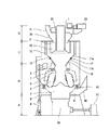
本発明の実施形態に係る竪型粉砕機について、図1〜図8を参照しながら以下詳細に説明する。図1は本発明の第1の実施形態に係る竪型粉砕機の構成を示す図である。図2は第1の実施形態に係る竪型粉砕機において粉砕ローラ交換の際に加圧フレームを持ち上げたときの構造を示す図である。図3は本発明の第2の実施形態に係る竪型粉砕機の構成並びに回収コーンの構造を示す図である。図4は本発明の第3の実施形態に係る竪型粉砕機の構成を示す図である。図5は本発明の第4の実施形態に係る竪型粉砕機の構成を示す図である。図6は第4の実施形態に係る竪型粉砕機において粉砕ローラ交換の際に加圧フレームを持ち上げたときの構造を示す図である。図7は本発明の第5の実施形態に係る竪型粉砕機の構成を示す図である。図8は第5の実施形態に係る竪型粉砕機において粉砕ローラ交換の際に加圧フレームを持ち上げたときの構造を示す図である。 A vertical crusher according to an embodiment of the present invention will be described in detail below with reference to FIGS. FIG. 1 is a diagram showing a configuration of a vertical crusher according to a first embodiment of the present invention. FIG. 2 is a diagram showing a structure when the pressure frame is lifted when the crushing roller is replaced in the vertical crusher according to the first embodiment. FIG. 3 is a diagram showing a configuration of a vertical crusher and a structure of a recovery cone according to the second embodiment of the present invention. FIG. 4 is a diagram showing a configuration of a vertical crusher according to the third embodiment of the present invention. FIG. 5 is a diagram showing the configuration of a vertical crusher according to the fourth embodiment of the present invention. FIG. 6 is a view showing a structure when the pressurizing frame is lifted when the crushing roller is replaced in the vertical crusher according to the fourth embodiment. FIG. 7 is a diagram showing a configuration of a vertical crusher according to the fifth embodiment of the present invention. FIG. 8 is a view showing a structure when the pressurizing frame is lifted when the crushing roller is replaced in the vertical crusher according to the fifth embodiment.
図面において、1は給炭管、2は粉砕テーブル、3は粉砕ローラ、4は粉砕ボール、5は加圧フレーム、6はローラブラケット、7はローラピボット、8は加圧ロッド、9は加圧装置、10は固定式分級機構、11は回収コーン、12は固定フィン、14は偏向リング、16はショートパス防止部材、17は回収コーンの接続部材、18は接合座、20は回転式分級機構、21は回転フィン、22は回転軸、23は分級機モータ、30は分配器、31は送炭管、40は一次空気ダクト、41は一次空気ウィンドボックス、42はスロート、50は粉砕テーブル用減速機、51は粉砕テーブル駆動用モータ、60は石炭(原炭)、61は一次空気、62は粉砕部から上昇してくる固気二相流、63は回転フィンで分離された粗粒子、64は製品微粉、65は分級部へ流入する粒子群、66は粗粒子、67は微粒子、Aは駆動部、Bは粉砕部、Cは分級部、Dは分配部、をそれぞれ表す。
In the drawings, 1 is a coal supply pipe, 2 is a grinding table, 3 is a grinding roller, 4 is a grinding ball, 5 is a pressure frame, 6 is a roller bracket, 7 is a roller pivot, 8 is a pressure rod, and 9 is pressure.
本発明の第1の実施形態に係る竪型粉砕機を示す図1において、竪型粉砕機は、駆動部A、粉砕部B、分級部C、及び分配部Dとから構成されている。給炭管1より供給された石炭60は、矢印で示すように回転している粉砕テーブル2の中心部に落下した後、回転に伴う遠心力によって粉砕テーブル2上を渦巻き状の軌跡を描いて外周部へ移動して、粉砕テーブル2とタイヤ状の粉砕ローラ3との間にかみ込まれて粉砕される。
In FIG. 1 showing the vertical crusher according to the first embodiment of the present invention, the vertical pulverizer includes a drive unit A, a pulverizing unit B, a classification unit C, and a distribution unit D. The
粉砕された石炭はスロート42から導入される熱風61によって、乾燥されながら上方に吹き上げられる。吹き上げられた粉体62のうち、粒度が大きいものは分級部Cへと搬送される途中で重力により落下し、粉砕部Bに戻される(一次分級)。分級部Cに到達した粒子群は、微粒子と粗粒子とに分級され(二次分級)、粗粒子は粉砕部Bへ落下して、再び粉砕される。一方、分級部Cを通過した微粒子は、分配器30において複数の送炭管31に分配されて、製品微粉64としてボイラへ送られる。
The pulverized coal is blown upward by the
粉砕部Bでは、粉砕ローラ3がローラブラケット6及びローラピボット7を介して加圧フレーム5により支持されており、加圧装置9により加圧ロッド8を介して加圧フレーム5を下方へ引っ張ることにより、粉砕ローラ3へ粉砕荷重が伝達する。
In the crushing part B, the crushing
分級部Cは、固定式分級機構10と回転式分級機構20の二段式構造になっている。固定式分級機構10は、固定フィン12と回収コーン11を有している。固定フィン12は分級部Cの天井面から下向きに吊り下げられ、かつ分級部Cの中心軸方向に対して任意の角度で多数枚固定されている(図11の固定フィン12を参照)。
The classification unit C has a two-stage structure of a fixed
第1の実施形態における回収コーン11は、固定フィン12の下側に逆円錐状(下方に向かって狭まる)に設けられており、加圧フレーム5により保持されている。回収コーン11上端の直径は固定フィン12の内径より小さくしている。また、回収コーン11の上部には、前記回収コーン11と固定フィン12の間を粉体がすり抜けるのを防止するための、ショートパス防止部材16が設けられている。このショートパス防止部材16は、回収コーン11と固定フィン12の間隔が十分に狭い場合は省略することも可能である。また、ショートパス防止部材16を回収コーン11とは分離した態様で、固定フィン12に接続しておき、その内周を回収コーンの外縁部が摺動するような形態としても差し支えない。
The
回転式分級機構20は、回転軸22と、それに支持された回転フィン21と、この回転軸22を回転駆動するモータを有している。回転フィン21は板の長手方向が分級部Cの中心軸方向とほぼ平行に延び、かつ分級部Cの中心軸に対して任意の角度で多数枚配置され、分級部C中心軸を軸心として回転する(図11の回転フィン21を参照)。製品微粉64の粒度分布は、回転式分級機構20の回転数で調整される。
The
本実施形態では、回収コーン11を固定フィン12から切り離して、加圧フレーム5の持ち上げ時に加圧フレーム5自体で保持することで、従来の粉砕機で必要であった回収コーンと加圧フレームの間の持ち上げ代(図12に示す持ち上げ代Lを参照)を省略することができる。
In the present embodiment, the
粉砕ローラ3を交換するために加圧フレーム5を持ち上げるときは、図2に示すように、回収コーン11が加圧フレーム5と連動して移動する。また、回収コーン11上端の直径を固定フィン12の内径より小さくしているので、回収コーン11は固定フィン12の内側を移動し、両者の干渉(接触)は起こらない(図2に示す回収コーン11の点線図示状態から実線図示状態の移動)。
When lifting the
次に、図3の(1),(2)に示す本発明の第2の実施形態に係る竪型粉砕機では、回転フィン21の外周側に粉砕機ケーシング上面板から垂下するように円筒状部材として偏向リング14を設置する。この場合、回収部材としては回収コーン11のみの構成とすることが可能であり(図9に示す固定フィン12を有しない)、部材数を低減し、装置構成の簡略化を図ることができる。
Next, in the vertical crusher according to the second embodiment of the present invention shown in (1) and (2) of FIG. 3, the cylindrical shape so as to hang down from the crusher casing top plate on the outer peripheral side of the
また、回収コーン11は従来設置されていた固定フィン12との干渉が起こらないため、回収コーン11の寸法形状等の自由度が高く、粉砕機の特性に応じた、多様な設計が可能となるメリットがある。例えば、回収コーン11の開口を大きくしたり、単純な逆円錐形状ではなく、その外縁部等の外周側の一部にリング状の部材等を付加して、スロート42からの粉体の吹き上げ流に対する衝突部材として用い、分散の機能を持たせる等してもよい(図3の(2)に示す構造を参照)。これにより、重力による1次分級を行う領域の空間高さが低くなっても、1次分級の性能を担保できる。
In addition, since the
さらに、図3の(2)に示すように、円筒状部材と円盤状部材を組み合わせて、回収コーン11上部を分離し、上下可動式のものとしてもよい。分離した回収コーン上部は、例えばケーシング上面板を貫通する吊下げ部材で支持し、これを上下させるようにすれば、粉砕機負荷等に応じてケーシング上面板との間に形成される流路断面積を可変とすることができる。なお、上下可動の手段はこれに限定されるものではない。
Furthermore, as shown in (2) of FIG. 3, a cylindrical member and a disk-like member may be combined to separate the upper part of the
図3の(2)に示す構造を採用することにより、粉体の流れをケーシング側壁及びケーシング上面板側へ向けるようにでき、偏向リング14の機能が発揮されやすくなるという利点がある。
By adopting the structure shown in FIG. 3 (2), there is an advantage that the flow of the powder can be directed to the casing side wall and the casing upper plate side, and the function of the
次に、図4は本発明の第3の実施形態を示し、従来技術を示す図13の竪型粉砕機で採用された粉砕ボール4(粉砕ローラ3に代えて)を用いた構成である。第3の実施形態では、第1の実施形態と同様に、回収コーン11は固定フィン12から切り離され、粉砕ボール4の加圧フレーム5で保持される。したがって、回収コーン11と加圧フレーム5間の持ち上げ代Lを省略することができる。また、回収コーン11の上部には、図1と同様に、ショートパス防止部材16を設けている。
Next, FIG. 4 shows a third embodiment of the present invention, which is a configuration using a grinding ball 4 (in place of the grinding roller 3) employed in the vertical crusher of FIG. 13 showing the prior art. In the third embodiment, similarly to the first embodiment, the
次に、図5に示す本発明の第4の実施形態に係る竪型粉砕機では、回収コーン11を通常は、スロート42からの吹き上げ流等によってずれることがないように固定フィン12の下部の支持部材に接続部材17により固定している。粉砕ローラ3を交換するために加圧フレーム5を持ち上げるときは、図6に示すように、接続部材17を取り外し、回収コーン11を加圧フレーム5に乗せて移動させる。ただし、回収コーン11と固定フィン12が構造的に干渉することを防ぐため、回収コーン11の上端の直径は固定フィン12の内径より小さくする必要がある。
Next, in the vertical crusher according to the fourth embodiment of the present invention shown in FIG. 5, the
また、図5と図6に示すように、回収コーン11に加圧フレーム5との接合座18を予め設けておけば、回収コーン11を加圧フレーム5に乗せる時の位置決めが容易となる。本実施形態では、粉砕テーブル2と粉砕ローラ3による石炭かみ込みによる加圧フレーム5の上昇分だけ、加圧フレーム5と回収コーン11の間に隙間を空けているが、従来の加圧フレームの持ち上げ代に比し1/10程度で足りる。
Further, as shown in FIGS. 5 and 6, if the
次に、図7に示す本発明の第5の実施形態に係る竪型粉砕機では、回収(部材)コーンを上下2つの部材に分割するとともに、上側回収部材(コーン)11aは固定フィン12下部に固定し、下側回収コーン11bは上側回収部材(コーン)11aの下部に接続部材17により固定している。
Next, in the vertical crusher according to the fifth embodiment of the present invention shown in FIG. 7, the recovery (member) cone is divided into two upper and lower members, and the upper recovery member (cone) 11 a is below the fixed
粉砕ローラ3を交換するために加圧フレーム5を持ち上げるときは、図8に示すように、接続部材17を取り外し、下側回収コーン11bを加圧フレーム5に乗せて移動させる。本実施形態では、上側回収部材(コーン)11aと回転式分級機構20との空間を利用して下側回収コーン11bを持ち上げるので、回収コーンと固定フィン12との構造的な干渉を気にする必要が無く、加圧フレーム5の持ち上げが容易に行うことが出来る。なお、上側回収部材11aは、図7に示したコーン形状のものに限らず、円筒状、円盤状、これらの組合せ等でもよい。
When lifting the
上述した本発明の各実施形態は、粉砕部の形態によって限定されることなく、図1に示す粉砕ローラ3や、図4に示す球状の粉砕ボール4以外の粉砕媒体にも適用可能である。
Each of the above-described embodiments of the present invention is not limited by the form of the pulverizing section, and can be applied to pulverizing media other than the pulverizing
以上説明したように、本発明の実施形態に係る竪型粉砕機は、次のような課題を達成するための構成を備えることを特徴とするものである。すなわち、竪型粉砕機では摩耗した粉砕ローラまたは粉砕ボールを交換する際に加圧フレームを上部に持ち上げる必要がある。従来の竪型粉砕機では、図12に示すように加圧フレーム5と回収コーン11の間に加圧フレームの持ち上げ代として高さLが設定されていた。一方、この高さLを無くして、粉砕機高さを低減しても竪型粉砕機の性能は影響を受けないことが種々の実験で明らかになった。
As described above, the vertical crusher according to the embodiment of the present invention is characterized by including a configuration for achieving the following problems. That is, in the vertical pulverizer, it is necessary to lift the pressure frame upward when the worn pulverizing roller or pulverizing ball is replaced. In the conventional vertical crusher, as shown in FIG. 12, a height L is set between the
本発明は、メンテナンスの面から加圧フレーム5と回収コーン11の干渉(接触)を避けなければならない加圧フレームの持ち上げ代を確保したまま、竪型粉砕機の高さを低減して装置の小型化と、性能の維持を両立するものである。
In the present invention, the height of the vertical crusher is reduced and the height of the vertical crusher is reduced while ensuring the lifting allowance of the pressure frame which must avoid the contact (contact) between the
具体的には、粉砕機構として、タイヤ状の粉砕ローラまたは球状の粉砕ボールと、前記粉砕ローラまたは粉砕ボールに対向する溝部を有する粉砕テーブルと、前記粉砕ローラまたは粉砕ボールに前記粉砕テーブルへの加圧力を伝達する加圧フレームとを備えており、
分級機構として、前記粉砕機構の上部に位置し、遠心力により固体粒子の分級を行う回転フィンと、少なくとも前記回転フィンの下方に配置された逆円錐状(下方に向かって狭まる)の回収コーンを有し、この回収コーンが上下に移動可能とすることを特徴とするものである。
Specifically, the grinding mechanism includes a tire-like grinding roller or a spherical grinding ball, a grinding table having a groove facing the grinding roller or the grinding ball, and the grinding roller or grinding ball added to the grinding table. A pressure frame that transmits pressure,
As a classification mechanism, a rotating fin that is positioned above the crushing mechanism and classifies solid particles by centrifugal force, and an inverted conical (condensed downward) recovery cone disposed at least below the rotating fin. And the recovery cone is movable up and down.
さらに、分級機構として、前記回転フィンの外周側に配され、粉砕機ケーシング上面板から垂下するように設けられる固定フィンを備え、前記回収部材は、回収コーンのほか、前記固定フィンに接続される支持部材を有し、この支持部材と回収コーンが分離可能に構成され、回収コーンの外縁部が前記固定フィンの内周側を上下に移動可能な回収コーンを有することを特徴とする。 Furthermore, as a classification mechanism, it is provided on the outer peripheral side of the rotary fin, and includes a fixed fin provided so as to hang down from the upper plate of the crusher casing, and the recovery member is connected to the fixed fin in addition to the recovery cone. It has a support member, the support member and the recovery cone are configured to be separable, and the outer edge of the recovery cone has a recovery cone that can move up and down on the inner peripheral side of the fixed fin.
また、前記分級機構は、前記回転フィンの外周側に粉砕機ケーシング上面板から垂下するように円筒状部材が設置されていることを特徴とする。また、前記回収コーンは、前記加圧フレームに支持可能とされ、加圧フレームの上下に伴って移動することを特徴とする。 Further, the classification mechanism is characterized in that a cylindrical member is installed on the outer peripheral side of the rotary fin so as to hang down from the crusher casing upper surface plate. The recovery cone can be supported by the pressure frame and moves along with the upper and lower sides of the pressure frame.
1 給炭管
2 粉砕テーブル
3 粉砕ローラ
4 粉砕ボール
5 加圧フレーム
6 ローラブラケット
7 ローラピボット
8 加圧ロッド
9 加圧装置
10 固定式分級機構
11 回収コーン
12 固定フィン
13 回収コーン支持板材
14 偏向リング
15 分級部上面板
16 ショートパス防止部材
17 回収コーンの接続部材
18 接合座
20 回転式分級機構
21 回転フィン
22 回転軸
23 分級機モータ
24 回転フィンの回転方向
30 分配器
31 送炭管
40 一次空気ダクト
41 一次空気ウィンドボックス
42 スロート
50 粉砕テーブル用減速機
51 粉砕テーブル駆動用モータ
60 石炭(原炭)
61 一次空気
62 粉砕部から上昇してくる固気二相流
63 回転フィンで分離された粗粒子
64 製品微粉
65 分級部へ流入する粒子群
66 粗粒子
67 微粒子
A 駆動部
B 粉砕部
C 分級部
D 分配部
L 加圧フレームの持ち上げ代
DESCRIPTION OF
61
Claims (5)
前記粉砕機構の上部に位置し遠心力により粉砕された固体粒子の分級を行う回転フィン、前記回転フィンの下方に配置され前記分級された固体粒子の回収を行う回収部材、を有する分級機構と、を備え、
前記回収部材は、上下に移動可能な回収コーンを有する
ことを特徴とする竪型粉砕機。 Grinding having a tire-like grinding roller or spherical grinding ball, a grinding table having a groove facing the grinding roller or the grinding ball, and a pressure frame for transmitting the pressure applied to the grinding table to the grinding roller or the grinding ball Mechanism,
A classification mechanism having a rotary fin that is positioned above the crushing mechanism and that classifies solid particles crushed by centrifugal force, and a recovery member that is disposed below the rotary fin and collects the classified solid particles; With
The vertical crusher characterized in that the recovery member has a recovery cone movable up and down.
前記回収コーンは、前記加圧フレームによって保持されて上下移動可能であることを特徴とする竪型粉砕機。 In claim 1,
The vertical pulverizer, wherein the recovery cone is held by the pressure frame and is movable up and down.
前記分級機構は、前記回転フィンの外周側に配され、粉砕機ケーシング上面板から垂下して設けられた固定フィンを有し、
前記回収コーンは、前記固定フィンの下部で接続部材により通常動作時には固定支持され、前記粉砕ローラまたは前記粉砕ボールの交換時には前記接続部材を外し当該回収コーンの上部外縁部が前記固定フィンの内周側を上下に移動可能である
ことを特徴とする竪型粉砕機。 In claim 1,
The classification mechanism is arranged on the outer peripheral side of the rotary fin, and has a fixed fin provided to hang down from the crusher casing top plate,
The recovery cone is fixedly supported by a connection member at a lower portion of the fixed fin during normal operation, and the connection member is removed when the pulverizing roller or the pulverized ball is replaced, and an upper outer edge of the recovery cone is an inner periphery of the fixed fin. A vertical crusher characterized in that it can move up and down.
前記分級機構は、前記回転フィンの外周側に配され、粉砕機ケーシング上面板から垂下して設けられた固定フィンを有し、
前記回収コーンは、前記固定フィンに固定された上側コーンと、前記上側コーンと接続部材で接続された下側コーンとからなり、
通常動作時には前記上側コーンと前記下側コーンとが前記接続部材で接続された一体的構造で前記固定フィンに固定支持され、前記粉砕ローラまたは前記粉砕ボールの交換時には前記接続部材を外し前記下側コーンが前記上側コーンおよび前記固定フィンの内周側を上下に移動可能である
ことを特徴とする竪型粉砕機。 In claim 1,
The classification mechanism is arranged on the outer peripheral side of the rotary fin, and has a fixed fin provided to hang down from the crusher casing top plate,
The recovery cone is composed of an upper cone fixed to the fixed fin, and a lower cone connected to the upper cone with a connecting member,
During normal operation, the upper cone and the lower cone are fixedly supported by the fixing fin in an integral structure in which the connection member is connected. When the grinding roller or the grinding ball is replaced, the connection member is removed and the lower side is removed. A vertical crusher characterized in that a cone is movable up and down on the inner peripheral side of the upper cone and the fixed fin.
前記回転フィンの外周側に粉砕機ケーシング上面板から垂下する円筒状部材を設け、前記粉砕機構で粉砕された固体粒子の吹き上げ流を前記円筒状部材によって偏向する
ことを特徴とする竪型粉砕機。 In claim 1 or 2,
A cylindrical pulverizer characterized in that a cylindrical member hanging from an upper surface plate of a pulverizer casing is provided on the outer peripheral side of the rotary fin, and the blown-up flow of solid particles pulverized by the pulverization mechanism is deflected by the cylindrical member. .
Priority Applications (1)
| Application Number | Priority Date | Filing Date | Title |
|---|---|---|---|
| JP2005247989A JP4799082B2 (en) | 2005-08-29 | 2005-08-29 | Vertical crusher |
Applications Claiming Priority (1)
| Application Number | Priority Date | Filing Date | Title |
|---|---|---|---|
| JP2005247989A JP4799082B2 (en) | 2005-08-29 | 2005-08-29 | Vertical crusher |
Publications (2)
| Publication Number | Publication Date |
|---|---|
| JP2007061684A true JP2007061684A (en) | 2007-03-15 |
| JP4799082B2 JP4799082B2 (en) | 2011-10-19 |
Family
ID=37924512
Family Applications (1)
| Application Number | Title | Priority Date | Filing Date |
|---|---|---|---|
| JP2005247989A Expired - Fee Related JP4799082B2 (en) | 2005-08-29 | 2005-08-29 | Vertical crusher |
Country Status (1)
| Country | Link |
|---|---|
| JP (1) | JP4799082B2 (en) |
Cited By (4)
| Publication number | Priority date | Publication date | Assignee | Title |
|---|---|---|---|---|
| KR20140138242A (en) | 2012-03-21 | 2014-12-03 | 바브콕-히다찌 가부시끼가이샤 | Vertical-type mill |
| CN107415086A (en) * | 2017-08-20 | 2017-12-01 | 杨松 | One kind prepares junked tire fine rubber powder steam protection mill |
| CN107521000A (en) * | 2017-08-20 | 2017-12-29 | 杨松 | One kind prepares junked tire fine rubber powder production line |
| WO2019082931A1 (en) * | 2017-10-27 | 2019-05-02 | ホソカワミクロン株式会社 | Powder processing device |
Families Citing this family (1)
| Publication number | Priority date | Publication date | Assignee | Title |
|---|---|---|---|---|
| CN107521001B (en) * | 2017-08-20 | 2019-11-05 | 吴雨潞 | A kind of application method preparing waste tire fine rubber powder steam protection mill |
Citations (3)
| Publication number | Priority date | Publication date | Assignee | Title |
|---|---|---|---|---|
| JPH10109045A (en) * | 1996-10-04 | 1998-04-28 | Babcock Hitachi Kk | Vertical roller mill |
| JP2000051723A (en) * | 1998-08-05 | 2000-02-22 | Babcock Hitachi Kk | Vertical roller mill |
| JP2001286779A (en) * | 2000-04-10 | 2001-10-16 | Babcock Hitachi Kk | Vertical roller grinder and method for replacing grinding roller |
-
2005
- 2005-08-29 JP JP2005247989A patent/JP4799082B2/en not_active Expired - Fee Related
Patent Citations (3)
| Publication number | Priority date | Publication date | Assignee | Title |
|---|---|---|---|---|
| JPH10109045A (en) * | 1996-10-04 | 1998-04-28 | Babcock Hitachi Kk | Vertical roller mill |
| JP2000051723A (en) * | 1998-08-05 | 2000-02-22 | Babcock Hitachi Kk | Vertical roller mill |
| JP2001286779A (en) * | 2000-04-10 | 2001-10-16 | Babcock Hitachi Kk | Vertical roller grinder and method for replacing grinding roller |
Cited By (10)
| Publication number | Priority date | Publication date | Assignee | Title |
|---|---|---|---|---|
| KR20140138242A (en) | 2012-03-21 | 2014-12-03 | 바브콕-히다찌 가부시끼가이샤 | Vertical-type mill |
| CN104203419A (en) * | 2012-03-21 | 2014-12-10 | 巴布考克日立株式会社 | Vertical-type mill |
| CN104203419B (en) * | 2012-03-21 | 2016-01-27 | 三菱日立电力系统株式会社 | vertical grinder |
| US9259739B2 (en) | 2012-03-21 | 2016-02-16 | Mitsubishi Hitachi Power Systems, Ltd. | Vertical-type mill |
| CN107415086A (en) * | 2017-08-20 | 2017-12-01 | 杨松 | One kind prepares junked tire fine rubber powder steam protection mill |
| CN107521000A (en) * | 2017-08-20 | 2017-12-29 | 杨松 | One kind prepares junked tire fine rubber powder production line |
| CN107521000B (en) * | 2017-08-20 | 2019-10-29 | 安徽成泰化学科技有限公司 | It is a kind of to prepare waste tire fine rubber powder production line |
| WO2019082931A1 (en) * | 2017-10-27 | 2019-05-02 | ホソカワミクロン株式会社 | Powder processing device |
| JP2019076874A (en) * | 2017-10-27 | 2019-05-23 | ホソカワミクロン株式会社 | Powder treatment apparatus |
| EP3702040A4 (en) * | 2017-10-27 | 2021-08-11 | Hosokawa Micron Corporation | POWDER PROCESSING DEVICE |
Also Published As
| Publication number | Publication date |
|---|---|
| JP4799082B2 (en) | 2011-10-19 |
Similar Documents
| Publication | Publication Date | Title |
|---|---|---|
| JP4550486B2 (en) | Classifier, vertical pulverizer including the same, and coal fired boiler apparatus including the vertical pulverizer | |
| JP4865865B2 (en) | Classification device, vertical pulverizer equipped with the same, and coal fired boiler device | |
| JP4811713B2 (en) | Cement clinker grinding equipment | |
| JP2017140573A (en) | Classifier, pulverization and classification device, and pulverized coal burning boiler | |
| JP4799082B2 (en) | Vertical crusher | |
| EP0804964B1 (en) | Pulverizer mill high performance classifier system | |
| JP5791556B2 (en) | Vertical crusher | |
| JP5177610B2 (en) | Cement clinker grinding equipment | |
| JP6627337B2 (en) | Biomass mill | |
| JP5825824B2 (en) | Vertical crushing device, pulverized coal production device, and coal-fired boiler plant equipped with the same | |
| JP5573078B2 (en) | Vertical mill | |
| JP4562871B2 (en) | Classifier and vertical mill | |
| JP2742066B2 (en) | Rotary classifier fine crusher | |
| JP5573172B2 (en) | Vertical crusher | |
| JP2012217920A (en) | Vertical mill | |
| JP4759285B2 (en) | Crusher | |
| JP6497079B2 (en) | Vertical crusher | |
| JP4771207B2 (en) | How to operate the vertical crusher | |
| JP4576577B2 (en) | Crusher | |
| JP2010201399A (en) | Vertical mill | |
| JP4272456B2 (en) | Classifier, vertical pulverizer and coal fired boiler device equipped with the same | |
| JP2011240233A (en) | Vertical type crushing device, and coal burning boiler device | |
| JP2774117B2 (en) | Mill with rotary classifier | |
| JPH07275729A (en) | Roller mill structure of its rotating base part | |
| JP2008062170A (en) | Classifier and vertical mill equipped with classifier |
Legal Events
| Date | Code | Title | Description |
|---|---|---|---|
| A621 | Written request for application examination |
Free format text: JAPANESE INTERMEDIATE CODE: A621 Effective date: 20080407 |
|
| A977 | Report on retrieval |
Free format text: JAPANESE INTERMEDIATE CODE: A971007 Effective date: 20100831 |
|
| A131 | Notification of reasons for refusal |
Free format text: JAPANESE INTERMEDIATE CODE: A131 Effective date: 20110517 |
|
| A521 | Request for written amendment filed |
Free format text: JAPANESE INTERMEDIATE CODE: A523 Effective date: 20110707 |
|
| TRDD | Decision of grant or rejection written | ||
| A01 | Written decision to grant a patent or to grant a registration (utility model) |
Free format text: JAPANESE INTERMEDIATE CODE: A01 Effective date: 20110726 |
|
| A01 | Written decision to grant a patent or to grant a registration (utility model) |
Free format text: JAPANESE INTERMEDIATE CODE: A01 |
|
| A61 | First payment of annual fees (during grant procedure) |
Free format text: JAPANESE INTERMEDIATE CODE: A61 Effective date: 20110802 |
|
| FPAY | Renewal fee payment (event date is renewal date of database) |
Free format text: PAYMENT UNTIL: 20140812 Year of fee payment: 3 |
|
| R150 | Certificate of patent or registration of utility model |
Ref document number: 4799082 Country of ref document: JP Free format text: JAPANESE INTERMEDIATE CODE: R150 Free format text: JAPANESE INTERMEDIATE CODE: R150 |
|
| S111 | Request for change of ownership or part of ownership |
Free format text: JAPANESE INTERMEDIATE CODE: R313111 |
|
| R350 | Written notification of registration of transfer |
Free format text: JAPANESE INTERMEDIATE CODE: R350 |
|
| R250 | Receipt of annual fees |
Free format text: JAPANESE INTERMEDIATE CODE: R250 |
|
| S533 | Written request for registration of change of name |
Free format text: JAPANESE INTERMEDIATE CODE: R313533 |
|
| R350 | Written notification of registration of transfer |
Free format text: JAPANESE INTERMEDIATE CODE: R350 |
|
| LAPS | Cancellation because of no payment of annual fees |