JP2007044402A - Endoscope - Google Patents
Endoscope Download PDFInfo
- Publication number
- JP2007044402A JP2007044402A JP2005234255A JP2005234255A JP2007044402A JP 2007044402 A JP2007044402 A JP 2007044402A JP 2005234255 A JP2005234255 A JP 2005234255A JP 2005234255 A JP2005234255 A JP 2005234255A JP 2007044402 A JP2007044402 A JP 2007044402A
- Authority
- JP
- Japan
- Prior art keywords
- light
- detection
- endoscope
- optical fiber
- radial direction
- Prior art date
- Legal status (The legal status is an assumption and is not a legal conclusion. Google has not performed a legal analysis and makes no representation as to the accuracy of the status listed.)
- Granted
Links
Images


Classifications
-
- A—HUMAN NECESSITIES
- A61—MEDICAL OR VETERINARY SCIENCE; HYGIENE
- A61B—DIAGNOSIS; SURGERY; IDENTIFICATION
- A61B1/00—Instruments for performing medical examinations of the interior of cavities or tubes of the body by visual or photographical inspection, e.g. endoscopes; Illuminating arrangements therefor
- A61B1/00002—Operational features of endoscopes
- A61B1/00043—Operational features of endoscopes provided with output arrangements
- A61B1/00045—Display arrangement
- A61B1/0005—Display arrangement combining images e.g. side-by-side, superimposed or tiled
-
- A—HUMAN NECESSITIES
- A61—MEDICAL OR VETERINARY SCIENCE; HYGIENE
- A61B—DIAGNOSIS; SURGERY; IDENTIFICATION
- A61B1/00—Instruments for performing medical examinations of the interior of cavities or tubes of the body by visual or photographical inspection, e.g. endoscopes; Illuminating arrangements therefor
- A61B1/005—Flexible endoscopes
- A61B1/009—Flexible endoscopes with bending or curvature detection of the insertion part
Landscapes
- Health & Medical Sciences (AREA)
- Life Sciences & Earth Sciences (AREA)
- Surgery (AREA)
- Biomedical Technology (AREA)
- Medical Informatics (AREA)
- Optics & Photonics (AREA)
- Pathology (AREA)
- Radiology & Medical Imaging (AREA)
- Biophysics (AREA)
- Engineering & Computer Science (AREA)
- Physics & Mathematics (AREA)
- Heart & Thoracic Surgery (AREA)
- Nuclear Medicine, Radiotherapy & Molecular Imaging (AREA)
- Molecular Biology (AREA)
- Animal Behavior & Ethology (AREA)
- General Health & Medical Sciences (AREA)
- Public Health (AREA)
- Veterinary Medicine (AREA)
- Instruments For Viewing The Inside Of Hollow Bodies (AREA)
- Endoscopes (AREA)
- Closed-Circuit Television Systems (AREA)
Abstract
【課題】 内視鏡の挿入管の形状を検知可能なまま、挿入管の細径化を図る。
【解決手段】 電子内視鏡20は、ライトガイド25、曲率検出ファイバ26、フィルタ27、および受光素子29を有する。ライトガイド25の周囲に曲率検出ファイバ26を配置する。ライトガイト25および曲率検出ファイバ26を挿入管22に沿って先端まで延ばす。単一のフィルタ27はライトガイド25の出射端25outと曲率検出ファイバ26の入射端26inとを覆う。曲率検出ファイバ26の出射端26outを受光素子29に接続する。曲率検出ファイバ26の所定の位置の所定の方向に光損失部28を設ける。フィルタ27は可視光を透過する。フィルタ27は可視光より波長の長い帯域の光成分を反射する。
【選択図】 図2
PROBLEM TO BE SOLVED: To reduce the diameter of an insertion tube while detecting the shape of the insertion tube of an endoscope.
An electronic endoscope includes a light guide, a curvature detecting fiber, a filter, and a light receiving element. A curvature detection fiber 26 is disposed around the light guide 25. The light guide 25 and the curvature detection fiber 26 are extended to the tip along the insertion tube 22. The single filter 27 covers the emission end 25out of the light guide 25 and the incidence end 26in of the curvature detection fiber 26. The exit end 26out of the curvature detection fiber 26 is connected to the light receiving element 29. An optical loss unit 28 is provided in a predetermined direction at a predetermined position of the curvature detection fiber 26. The filter 27 transmits visible light. The filter 27 reflects light components in a band having a wavelength longer than that of visible light.
[Selection] Figure 2
Description
本発明は、内視鏡の使用時の挿入管の形状を検知し得る内視鏡に関する。 The present invention relates to an endoscope that can detect the shape of an insertion tube when the endoscope is used.
従来、内視鏡の使用時の挿入管の形状を検出することが求められている。側面に光吸収部を設けた光ファイバを用いた帯状姿勢検出センサ(特許文献1参照)などを利用して、内視鏡の挿入管の姿勢を検出することが、本件出願人などにより提案されている(特許文献2〜特許文献4参照)。 Conventionally, it has been required to detect the shape of an insertion tube when an endoscope is used. The present applicant has proposed that the posture of the insertion tube of the endoscope be detected using a belt-like posture detection sensor (see Patent Document 1) using an optical fiber having a light absorbing portion provided on the side surface. (See Patent Documents 2 to 4).
一方、内視鏡の挿入管に帯状姿勢検出センサを設けることにより、挿入管の径が太くなる点が問題であった。すなわち、医療用内視鏡であれば被験者の苦痛を増大させる可能性があった。また、帯状姿勢検出センサでは、形状を検出するために新たな光源を用いる必要があり、内視鏡システム全体の大型化および複雑化することが問題であった。 On the other hand, there is a problem in that the diameter of the insertion tube is increased by providing a band-shaped posture detection sensor on the insertion tube of the endoscope. That is, if it is a medical endoscope, there is a possibility of increasing the pain of the subject. Further, in the belt-like posture detection sensor, it is necessary to use a new light source in order to detect the shape, and there is a problem that the entire endoscope system becomes large and complicated.
また、帯状姿勢検出センサより巾の小さいセンサとして、複数の光ファイバと反射鏡とを用いた姿勢検出センサが提案されている(特許文献5参照)。しかし、このような反射鏡を有する姿勢検出センサを用いても、用いていない場合に比べて内視鏡の挿入管が太くなるので、挿入管の更なる細径化が求められていた。また、帯状姿勢検出センサと同様に光源が必要であるため、内視鏡システム全体の大型化および複雑化の問題は解消されないままであった。
したがって、本発明では挿入管の形状を検知可能で、かつ挿入管を細径化でき、システム全体の構成を簡潔にさせることが可能な内視鏡の提供を目的とする。 Therefore, an object of the present invention is to provide an endoscope that can detect the shape of the insertion tube, can reduce the diameter of the insertion tube, and can simplify the configuration of the entire system.
本発明の内視鏡は、本体と、本体から延び可撓性を有する挿入体と、挿入体に沿って先端まで延び光を出射するための供給用出射部と光を入射するための供給用入射部とを有し第1の波長帯域の光である第1の光と前記第1の波長帯域と異なる第2の波長帯域の波長の光である第2の光とを供給用入射部から供給用出射部へ伝達する供給用光伝達手段と、挿入体の先端まで延び光を入射するための検出用入射部と光を出射するため検出用出射部とを有し第1の光を検出用入射部から検出用出射部まで伝達し曲がり角度に応じて第1の光の伝達量が変化する検出用光伝達手段と、第2の光を透過させ第1の光を反射する反射部材によって形成され供給用出射部と検出用入射部とを一体的に覆うフィルタとを備え、供給用出射部と検出量入射部は挿入体の先端に設けられ、フィルタを透過した第2の光によって挿入体の先端付近を照明可能であることを特徴としている。 The endoscope of the present invention includes a main body, a flexible insert extending from the main body, a supply emitting section for emitting light extending along the insert to the tip, and for supplying light. A first light having an incident portion and a second light having a wavelength in a second wavelength band different from the first wavelength band from the supply incident portion; Detecting the first light having a supply light transmission means for transmitting to the supply emission section, a detection incident section extending to the distal end of the insert and entering the light, and a detection emission section for emitting the light A detection light transmitting means that transmits from the incident portion to the detection emitting portion and changes the amount of transmission of the first light according to the bending angle, and a reflecting member that transmits the second light and reflects the first light And a filter that integrally covers the supply emitting portion and the detection incident portion. Provided at the tip of the inclusion bodies are characterized in that the second light transmitted through the filter is possible illuminate the vicinity of the distal end of the insert.
なお、検出用光伝達手段は第1の光を伝達する第1の光ファイバを有することが好ましい。さらに、第1の光ファイバに第1の光を損失させる光損失部を本体から第1の距離だけ離れた位置の第1の光ファイバの中心から第1の径方向に形成することにより、曲がり角度に応じて第1の光の伝達量が変化することが好ましい。 In addition, it is preferable that the light transmission means for detection has the 1st optical fiber which transmits 1st light. Furthermore, by forming a light loss portion for losing the first light in the first optical fiber in the first radial direction from the center of the first optical fiber at a position away from the main body by the first distance, It is preferable that the transmission amount of the first light changes according to the degree.
また、検出用光伝達手段は第1の光を伝達する第2の光ファイバを有し、第2の光ファイバには光損失部が本体から第1の距離だけ離れた位置の第2の光ファイバの中心から第1の径方向とは異なる向きである第2の径方向に形成され、第2の光ファイバの曲がり角度に応じて第2の光ファイバにおける第1の光の伝達量が変化することが好ましい。 Further, the detection light transmission means includes a second optical fiber that transmits the first light, and the second optical fiber has a second light at a position where the optical loss portion is separated from the main body by the first distance. The amount of transmission of the first light in the second optical fiber changes in accordance with the bending angle of the second optical fiber, which is formed in the second radial direction that is different from the first radial direction from the center of the fiber. It is preferable to do.
また、検出用光伝達手段は第1の光を伝達する第3の光ファイバを有し、第3の光ファイバには光損失部が本体から第1の距離とは異なる第2の距離だけ離れた位置の第3の光ファイバの中心から第3の径方向に形成され、第3の光ファイバの曲がり角度に応じて第3の光ファイバにおける第1の光の伝達量が変化することが好ましい。 Further, the detection light transmission means has a third optical fiber for transmitting the first light, and the optical loss portion is separated from the main body by a second distance different from the first distance in the third optical fiber. Preferably, the transmission amount of the first light in the third optical fiber is changed in accordance with the bending angle of the third optical fiber. .
また、検出用光伝達手段は第1の光を伝達する第2、第4の光ファイバを有し、第2の光ファイバには光損失部が本体からの距離が第1の距離であって第2の光ファイバの中心から第1の径方向とは異なる向きである第2の径方向に形成され、第4の光ファイバには光損失部が本体からの距離が第2の距離であって第4の光ファイバの中心から第3の径方向とは異なる向きである第4の径方向に形成され、第2、第4の光ファイバの曲がり角度に応じて第2、第4の光ファイバにおける第1の光の伝達量が変化することが好ましい。 The detection light transmission means has second and fourth optical fibers for transmitting the first light, and the second optical fiber has a light loss portion at a first distance from the main body. The second optical fiber is formed in a second radial direction that is different from the first radial direction from the center of the second optical fiber, and the optical loss portion of the fourth optical fiber has a second distance from the main body. The fourth optical fiber is formed in a fourth radial direction that is different from the third radial direction from the center of the fourth optical fiber, and the second and fourth light beams according to the bending angles of the second and fourth optical fibers. It is preferable that the transmission amount of the first light in the fiber changes.
また、第1の径方向と第3の径方向とがあるいは第2の径方向と第4の径方向とが同じ向きであることが好ましい。さらには、第1の径方向と第2の径方向とがあるいは第3の径方向と第4の径方向とが互いに垂直であることが好ましい。 In addition, it is preferable that the first radial direction and the third radial direction or the second radial direction and the fourth radial direction are the same direction. Furthermore, it is preferable that the first radial direction and the second radial direction or the third radial direction and the fourth radial direction are perpendicular to each other.
また、検出用出射部から出射する第1の光の光量を検出する光量検出手段を備えることが好ましい。 Moreover, it is preferable to provide a light amount detection means for detecting the light amount of the first light emitted from the detection emitting portion.
また、本発明の内視鏡光源ユニットは、本体と、本体から延び可撓性を有する挿入体と、挿入体に沿って先端まで延び光を出射するための供給用出射部と光を入射するための供給用入射部とを有し第1の波長帯域の光である第1の光と前記第1の波長帯域と異なる第2の波長帯域の波長の光である第2の光とを供給用入射部から供給用出射部へ伝達する供給用光伝達手段と、挿入体の先端まで延び光を入射するための検出用入射部と光を出射するため検出用出射部とを有し第1の光を検出用入射部から検出用出射部まで伝達し曲がり角度に応じて第1の光の伝達量が変化する検出用光伝達手段と、第2の光を透過させ第1の光を反射する反射部材によって形成され供給用出射部と検出用入射部とを一体的に覆うフィルタとを備え、供給用出射部と検出量入射部は挿入体の先端に設けられ、フィルタを透過した第2の光によって挿入体の先端付近を照明可能である内視鏡における供給用入射部と光学的に接続され、第1、第2の光を発光する光源と、供給用入射部と光源との間に配置され第2の光を遮光させ第1の光を透過させる遮光部を有する絞りとを備えることを特徴としている。 The endoscope light source unit according to the present invention also receives light from a main body, a flexible insert extending from the main body, a supply emitting section for emitting light extending along the insert to the tip. For supplying a first light that is light in a first wavelength band and a second light that is light in a second wavelength band different from the first wavelength band A first light transmitting means for transmitting light from the light incident portion to the light emitting portion for supply, a light incident light portion extending to the tip of the insert and for receiving light; and a light emitting portion for detection for emitting light. Light is transmitted from the detection incident portion to the detection emission portion, and the detection light transmission means for changing the amount of transmission of the first light according to the bending angle, and the second light is transmitted and the first light is reflected. Provided with a filter formed integrally by the reflecting member that integrally covers the emitting part for supply and the incident part for detection. And the detection amount incident portion is provided at the distal end of the insert, and is optically connected to the supply incident portion in the endoscope capable of illuminating the vicinity of the distal end of the insert by the second light transmitted through the filter. And a light source that emits the second light, and a diaphragm having a light-shielding portion that is disposed between the supply incident portion and the light source and shields the second light and transmits the first light. .
また、本発明の第1の内視鏡姿勢検出ユニットは、本体と、本体から延び可撓性を有する挿入体と、挿入体に沿って先端まで延び光を出射するための供給用出射部と光を入射するための供給用入射部とを有し第1の波長帯域の光である第1の光と前記第1の波長帯域と異なる第2の波長帯域の波長の光である第2の光とを供給用入射部から供給用出射部へ伝達する供給用光伝達手段と、挿入体の先端まで延び光を入射するための検出用入射部と光を出射するため検出用出射部とを有し第1の光を検出用入射部から検出用出射部まで伝達し曲がり角度に応じて第1の光の伝達量が変化する検出用光伝達手段と、第2の光を透過させ第1の光を反射する反射部材によって形成され供給用出射部と検出用入射部とを一体的に覆うフィルタとを備え、供給用出射部と検出量入射部は挿入体の先端に設けられ、フィルタを透過した第2の光によって挿入体の先端付近を照明可能である内視鏡における検出用出射部から出射する第1の光の光量を検出する光量検出手段と、光量検出手段により検出された光量に基づいて挿入体の曲がり角度を算出する算出手段とを備えることを特徴としている。 The first endoscope posture detection unit of the present invention includes a main body, a flexible insertion body extending from the main body, and a supply emitting section for emitting light extending to the tip along the insertion body. A first incident light having a first incident light source, and a second light having a wavelength in a second wavelength band different from the first wavelength band. A supply light transmitting means for transmitting light from the supply incident part to the supply emission part, a detection incident part extending to the distal end of the insert, and a detection emission part for emitting light. The first light is transmitted from the detection incident portion to the detection emission portion, and the transmission amount of the first light is changed according to the bending angle, and the second light is transmitted through the first light. A filter that is formed of a reflecting member that reflects the light of and integrally covers the emission part for supply and the incident part for detection, The supply emitting portion and the detection amount incident portion are provided at the distal end of the insertion body, and are emitted from the detection emission portion in the endoscope capable of illuminating the vicinity of the distal end of the insertion body by the second light transmitted through the filter. A light amount detecting means for detecting the light amount of the light, and a calculating means for calculating a bending angle of the insert based on the light amount detected by the light amount detecting means.
また、本発明の第2の内視鏡姿勢検出ユニットは、本体と、本体から延び可撓性を有する挿入体と、挿入体に沿って先端まで延び光を出射するための供給用出射部と光を入射するための供給用入射部とを有し第1の波長帯域の光である第1の光と前記第1の波長帯域と異なる第2の波長帯域の波長の光である第2の光とを供給用入射部から供給用出射部へ伝達する供給用光伝達手段と、挿入体の先端まで延び光を入射するための検出用入射部と光を出射するため検出用出射部とを有し第1の光を検出用入射部から検出用出射部まで伝達し曲がり角度に応じて第1の光の伝達量が変化する検出用光伝達手段と、第2の光を透過させ第1の光を反射する反射部材によって形成され供給用出射部と検出用入射部とを一体的に覆うフィルタと、検出用出射部から出射する第1の光の光量を検出する光量検出手段とを備え、供給用出射部と検出量入射部は挿入体の先端に設けられ、フィルタを透過した第2の光によって挿入体の先端付近を照明可能である内視鏡の光量検出手段により検出された光量に基づいて、挿入体の曲がり角度を算出する算出手段とを備えることを特徴としている。 The second endoscope posture detection unit of the present invention includes a main body, a flexible insertion body extending from the main body, and a supply emitting section for emitting light extending to the tip along the insertion body. A first incident light having a first incident light source, and a second light having a wavelength in a second wavelength band different from the first wavelength band. A supply light transmitting means for transmitting light from the supply incident part to the supply emission part, a detection incident part extending to the distal end of the insert, and a detection emission part for emitting light. The first light is transmitted from the detection incident portion to the detection emission portion, and the transmission amount of the first light is changed according to the bending angle, and the second light is transmitted through the first light. A filter that is formed by a reflective member that reflects the light of the light and integrally covers the supply emitting portion and the detecting incident portion; A light amount detecting means for detecting the light amount of the first light emitted from the projecting unit, the supply emitting unit and the detection amount incident unit being provided at the tip of the insert, and the insert by the second light transmitted through the filter And a calculating means for calculating the bending angle of the insert based on the light amount detected by the light amount detecting means of the endoscope capable of illuminating the vicinity of the distal end of the endoscope.
また、本発明の内視鏡システムは、本体と本体から延び可撓性を有する挿入体と挿入体に沿って先端まで延び光を出射するための供給用出射部と光を入射するための供給用入射部とを有し第1の波長帯域の光である第1の光と前記第1の波長帯域と異なる第2の波長帯域の波長の光である第2の光とを供給用入射部から供給用出射部へ伝達する供給用光伝達手段と挿入体の先端まで延び光を入射するための検出用入射部と光を出射するため検出用出射部とを有し第1の光を検出用入射部から検出用出射部まで伝達し曲がり角度に応じて第1の光の伝達量が変化する検出用光伝達手段と第2の光を透過させ第1の光を反射する反射部材によって形成され供給用出射部と検出用入射部とを一体的に覆うフィルタとを有し供給用出射部と検出量入射部は挿入体の先端に設けられフィルタを透過した第2の光によって挿入体の先端付近を照明可能である内視鏡と、供給用入射部と光学的に接続され第1、第2の光を発光する光源と供給用入射部と光源との間に配置され第2の光を遮光させ第1の光を透過させる遮光部によって形成される絞りとを有する内視鏡光源ユニットと、検出用出射部から出射する第1の光の光量を検出する光量検出手段と、光量検出手段により検出された光量に基づいて挿入体の曲がり角度を算出する算出手段と、内視鏡により撮像された被写体像と曲がり角度に応じた挿入体の形状とを表示するモニタとを備えることを特徴としている。 The endoscope system of the present invention includes a main body, a flexible insert extending from the main body, a supply emitting section for emitting light extending along the insert to the tip, and a supply for entering light. A first incident light having a first wavelength band and a second incident light having a second wavelength band different from the first wavelength band. The first light is detected by the supply light transmitting means for transmitting from the supply to the supply emission part, the detection incident part for entering the light extending to the tip of the insert, and the detection emission part for emitting the light. Formed by a detection light transmission means that transmits from the incident portion to the detection emission portion and changes the amount of transmission of the first light according to the bending angle, and a reflecting member that transmits the second light and reflects the first light And a supply emitting portion and a detection amount incident. Is provided at the distal end of the insertion body and is optically connected to an endoscope for supplying the vicinity of the distal end of the insertion body with the second light transmitted through the filter, and the first and second lights are optically connected to the supply incident portion. An endoscope light source unit including a light source that emits light, a supply incident portion, and a diaphragm formed by a light shielding portion that blocks the second light and transmits the first light, and a detection emission. A light amount detecting means for detecting the light amount of the first light emitted from the unit, a calculating means for calculating a bending angle of the insert based on the light amount detected by the light amount detecting means, and a subject image captured by the endoscope And a monitor for displaying the shape of the insert according to the bending angle.
本発明によれば、挿入管の姿勢、すなわち形状を検出可能な内視鏡を細径化させることが可能である。また、被写体を照明するための光源を、形状を検出するための光源として共用することにより、内視鏡システム全体の大型化・複雑化を避けることが可能となる。 According to the present invention, it is possible to reduce the diameter of the endoscope that can detect the posture, that is, the shape of the insertion tube. Further, by sharing the light source for illuminating the subject as the light source for detecting the shape, it is possible to avoid the enlargement and complication of the entire endoscope system.
以下、本発明の実施形態について図面を参照して説明する。 Embodiments of the present invention will be described below with reference to the drawings.
まず、内視鏡システム10の全体構成について図1を用いて簡潔に説明する。図1は、本発明の一実施形態を適用した内視鏡を有する内視鏡システムの外観図である。
First, the overall configuration of the
内視鏡システム10は、電子内視鏡20、内視鏡プロセッサ40、およびモニタ70によって構成される。電子内視鏡20は、コネクタ21を介して内視鏡プロセッサ40に接続される。モニタ70もコネクタ(図示せず)を介して内視鏡プロセッサ40に接続される。
The
電子内視鏡20の挿入管22の先端近辺の被写体(図示せず)は、電子内視鏡20内部を通るライトガイド(図示せず)を介して内視鏡プロセッサ40に設けられる光源(図示せず)から照明光が照射される。照明光が照射される被写体は、電子内視鏡20の挿入管22の先端に設けられるCCD等の撮像素子(図示せず)により撮像される。
A subject (not shown) near the distal end of the
撮像された画像は映像信号として内視鏡プロセッサ40に送られる。内視鏡プロセッサ40に送られた映像信号は所定の処理が行われた後、モニタ70に送られ、そこで被写体像が表示される。
The captured image is sent to the
次に図2を用いて、電子内視鏡20の内部構成について説明する。図2は、電子内視鏡20の内部構成を概略的に示すブロック図である。
Next, the internal configuration of the
電子内視鏡20は、本体23、挿入管22、ケーブル24、およびコネクタ21によって構成される。挿入管22は、本体23から延ばされるように取り付けられる。コネクタ21は、ケーブル24を介して本体23に取り付けられる。
The
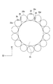
ライトガイド25が、コネクタ21から挿入管22に沿って先端まで延ばされるように設けられる。ライトガイド25の周囲には図3に示すようにライトガイド25を芯にして取り囲むように、複数の曲率検出ファイバ26が設けられる。曲率検出ファイバ26も、コネクタ21から挿入管22に沿って先端まで延ばされる。
A
ライトガイド25は複数の光ファイバによって形成され、可視光成分である第1の光成分と可視光より波長の長い帯域の光成分である第2の光成分を、入射端25inから出射端25outまで伝達可能である。曲率検出ファイバ26は、少なくとも第2の光成分を、入射端26inから出射端26outまで伝達可能である。
The
ライトガイド25の出射端25outおよび曲率検出ファイバ26の入射端26inは、挿入管22の先端付近に配置される。ライトガイド25の出射端25outおよび曲率検出ファイバ26の入射端26inは、単一のフィルタ27によって覆われる。
The exit end 25out of the
フィルタ27は、光学ガラス部材を蒸着することにより、ライトガイド25の出射端25outおよび曲率検出ファイバ26の入射端26inに固定される。フィルタ27を形成するガラス部材には、第1の光成分を透過させ、第2の光成分を反射することが可能な部材が用いられる。
The
曲率検出ファイバ26には、光損失部28が設けられる。光損失部28に入射する第2の光成分は、部分的に光損失部28に吸収され、損失する。光損失部28が設けられる位置と方向とは、曲率検出ファイバ26ごとに定められている。
The
なお、光損失部28が設けられる位置は、本体23からの距離がそれぞれの曲率検出ファイバ26に定められた長さとなるように定められる。また、光損失部が設けられる方向は、曲率検出ファイバ26の長手方向に平行な断面において、曲率検出ファイバ26の中心から第1の径方向、または曲率検出ファイバ26の中心から第1の径方向とは90°傾いた第2の径方向のいずれかである。
The position where the
光損失部の設けられる位置と方向について、図4、図5を用いてさらに説明する。図4は、ライトガイド25の周囲の複数の曲率検出ファイバ26における光損失部28の位置を示すための図である。図5は、ライトガイド25の周囲の複数の曲率検出ファイバ26における光損失部28の方向を示すための図である。
The position and direction in which the light loss part is provided will be further described with reference to FIGS. FIG. 4 is a diagram for illustrating the positions of the
図4に示すように、第1、第2の曲率検出ファイバ26a、26bにおいては、同じ位置に光損失部28が設けられる。また、第3、第4の曲率検出ファイバ26c、26dにおいては、同じ位置に光損失部28が設けられる。ただし、第1、第3の曲率検出ファイバ26a、26cにおける光損失部28が設けられる位置は異なっている。
As shown in FIG. 4, in the first and second
このように、一つの組を形成する2本の曲率検出ファイバ26には、光損失部28が同じ位置に設けられる。ただし、光損失部28の設けられる位置は、組毎に異なるように定められる。
Thus, the
また図5に示すように、第1、第3の曲率検出ファイバ26a、26cでは、ファイバの中心から第1の径方向D1に光損失部28が設けられる。一方、第2、第4の曲率検出ファイバ26b、26dでは、ファイバの中心から第2の径方向D2に光損失部28が設けられる。
As shown in FIG. 5, in the first and third
このように、光損失部28の設けられる方向は、一つの組を形成する2本の曲率検出ファイバ26の一方においてはファイバの中心から第1の径方向D1に定められ、他方においてはファイバの中心から第2の径方向D2に定められる。
Thus, the direction in which the
曲率検出ファイバ26の出射端26outから出射される光の光量に基づいて、光損失部28における曲率検出ファイバ26の曲げ角度を求めることが可能である。以下に、その原理について簡単に説明する。
Based on the amount of light emitted from the exit end 26out of the
曲率検出ファイバ26は前述のように光ファイバであり、コアにクラッドを被膜することにより形成される。コアに入射される光は、コアとクラッドの界面において全反射されることにより光量が実質的に損失されること無く、入射端26inから出射端26outまで伝達される。一方、光損失部28に入射する光は完全にまたは一部が吸収される。したがって、光損失部28に入射する光が多くなるほど、光の損失が大きくなる。
The
図6に示すように、光損失部28が設けられる方向と逆の方向(図6において下方向)に曲率検出ファイバ26が曲がるほど、光損失部28に入射する光Lは多くなる。一方、図7に示すように、光損失部28が設けられる方向に曲率検出ファイバ26が曲がるほど、光損失部28に入射する光Lは少なくなる。
As shown in FIG. 6, as the
一定の光量の光を曲率検出ファイバ26に入射するとき、出射端26outからの光の出射量と光損失部28における曲げ角度とは一定の対応関係を有する。したがって、出射端26outにおける光の受光量を検出することにより、光損失部28における曲率検出ファイバ26および挿入管22の曲げ角度が求められる。
When a certain amount of light enters the
例えば、光損失部28の設けられる位置の異なる6本の曲率検出ファイバ26を用いると、光損失部28が設けられる6箇所における挿入管22の曲げ角度が求められる。図8に示すように、それぞれの光損失部26が設けられるポイントPにおける曲げ角度と隣合うポイントPの距離とによって挿入管22の形状を検知することが可能になる。
For example, when six
なお、第1、第2方向D1、D2に光損失部28が設けられた曲率検出ファイバ26からは、それぞれ第1、第2方向D1、D2への曲げ角度が検出される。したがって、両方向への曲げ角度から、光損失部28の曲がる方向と曲げ角度とを求めることが可能である。
Note that bending angles in the first and second directions D1 and D2 are detected from the
曲率検出ファイバ26の出射端26outは、別々の受光素子29に接続される(図2参照)。受光素子29は例えばフォトダイオードであって、受光量を検知可能である。すなわち、受光量に応じた電気信号が曲率信号として出力される。
The exit end 26out of the
挿入管22の先端には、配光レンズ30、対物レンズ31、および撮像素子32が設けられる。フィルタ27から出射する光が配光レンズ30を介して、先端付近の被写体に照射される。対物レンズ31は、被写体への照射光の反射光を撮像素子32の受光面に結像させる。撮像素子32が撮像した被写体像は、画像信号として生成される。
At the distal end of the
後述するように、コネクタ21を介して電子内視鏡20を内視鏡プロセッサ40に接続することにより、受光素子29および撮像素子32が電気的に、ライトガイド25が光学的に内視鏡プロセッサ40と接続される。
As will be described later, by connecting the
次に、内視鏡プロセッサ40の構成について図9を用いて説明する。図9は、内視鏡プロセッサ40の内部構成を概略的に示すブロック図である。
Next, the configuration of the
内視鏡プロセッサ40は、光源ユニット50、信号処理ユニット60、撮像素子駆動回路41、およびタイミングジェネレータ42などによって構成される。光源ユニット50によって、電子内視鏡20に用いられる光が供給される。また、信号処理ユニット60によって、画像信号の処理、受光素子29から出力される曲率信号の処理が行われる。
The
撮像素子32は、撮像素子と電気的に接続される撮像素子駆動回路41によって、撮像などの動作が制御される。また、撮像素子駆動回路41はタイミングジェネレータ42に接続されており、撮像素子32の動作を制御するためのタイミング信号が、タイミングジェネレータ42から出力される。
The operation of the
光源ユニット50は、ランプ51、絞り52、集光レンズ53、モータM、電源54、および絞り駆動回路55によって構成される。電子内視鏡20のコネクタ21を接続することにより、ランプ51とライトガイド25とが光学的に接続される。
The
ランプ51には、高輝度な光であって、第1、第2の光成分を照射できるキセノンランプやハロゲンランプなどが用いられる。ランプ51への電力は、電源54から供給される。
As the
ランプ51からの照射光をライトガイド25の入射端25inに導くための光路中に絞り52および集光レンズ53が設けられる。ランプ51から照射される略平行な光束の光は、集光レンズ53で集光されて入射端25inに入射される。
A
入射端25inに入射させる光の光量調整は、絞り52を駆動することにより実行される。絞り52は、絞り駆動回路55により動作が制御されるモータMにより駆動される。なお、絞り52には、第1の光成分より波長の短い光を遮断し、第2の光成分より波長の長い光を透過させる材質によって遮光部が形成される。したがって、入射端25inに入射させる光の内、第1の光成分のみの光量調整が行われる。一方、第2の光成分はそのままの光量で入射端25inに入射される。
The adjustment of the amount of light incident on the
信号処理ユニット60は、前段信号処理回路61、画像メモリ62、後段信号処理回路63、曲率位置変換回路64、および形状メモリ65等によって構成される。電子内視鏡20のコネクタ21を接続することにより、撮像素子32と前段信号処理回路61とが、受光素子29と曲率位置変換回路64とが電気的に接続される。
The
撮像素子32が生成した画像信号は、前段信号処理回路61に送られる。前段信号処理回路61において、アナログ信号である画像信号はA/D変換され、デジタル信号に変換された画像信号に対して、ホワイトバランスやγ補正などの所定の処理が施される。
The image signal generated by the
所定の処理が施された画像信号は画像メモリ62に送られ、格納される。なお、画像信号に基づいて前段信号処理回路61では1フレーム全体での受光量が検出される。検出された全体の受光量は絞り駆動回路55に出力される。全体での受光量に基づいて絞り駆動回路55が絞り52を駆動することによって、被写体を照明する光の光量が適切になるように調整される。
The image signal subjected to the predetermined processing is sent to the
画像メモリ62に格納された画像信号は、後段信号処理回路63に出力される。後段信号処理回路63に出力するタイミングは、タイミングジェネレータ42により制御される。後段信号処理回路63において、画像信号はD/A変換され、エンコードなどの所定の処理が行われる。後段信号処理回路63はモニタ70に接続されており、撮像した被写体像がモニタ70に表示される。
The image signal stored in the
受光素子29が生成した曲率信号は、曲率位置変換回路64に送られる。曲率位置変換回路64では、隣合う光損失部28間の距離と第1、第2方向D1、D2への曲げ角度に相当する曲率信号とに基づいて、それぞれの光損失部28の3次元座標が求められる。
The curvature signal generated by the
光損失部28の3次元座標は形状メモリ65に送られて、記憶される。形状メモリ65に記憶された光損失部28の3次元座標は、後段信号処理回路63に送られる。後段信号処理回路63に3次元座標を送るタイミングは、タイミングジェネレータ42により制御される。
The three-dimensional coordinates of the
後段信号処理回路63において、光損失部28の3次元座標に基づいて、スムージング処理が行われる。すなわち、光損失部28を結ぶ直線が、滑らかな曲線に変換される。このように、挿入管22の形状は、求められた曲線によって表されている。挿入管22の形状に相当する形状信号は、後段信号処理回路63によってD/A変換される。D/A変換された形状信号に所定の処理が行われる。
In the post-stage
後段信号処理回路63では、モニタ70に撮像した被写体像および挿入管22の形状を表示するために、モニタ70上におけるそれぞれの表示領域の割当てなどの処理が行われる。所定の処理が行われた画像信号および形状信号がモニタ70に出力される。画像信号および形状信号に基づいて、モニタ70の内視鏡画像表示領域IAには被写体像が、内視鏡形状表示領域SAには挿入管22の形状が表示される(図10参照)。
In the post-stage
従来の帯状姿勢検出センサおよび反射鏡を用いた姿勢検出センサの場合、1つの位置の、1方向の曲がり角度を検出するのに光ファイバを往復させる必要があった。一方、本実施形態でが、照明光を伝達するためのライトガイドを、形状検出用の光を先端部まで伝達させる光ファイバとして共用させることにより、挿入管22内に配置する光ファイバの本数を減らすことが可能となる。
In the case of a conventional posture detection sensor using a belt-like posture detection sensor and a reflecting mirror, it is necessary to reciprocate an optical fiber in order to detect a bending angle in one direction at one position. On the other hand, in this embodiment, the number of optical fibers arranged in the
したがって、以上のような本実施形態の電子内視鏡20によれば、挿入管22内に配置する光ファイバの本数が減らせるので、挿入管22の形状を検出可能な内視鏡の細径化を図ることが可能である。
Therefore, according to the
また、照明光の供給のために用いられるランプ51を、形状検出用の光の光源として共用することにより、新たな光源装置が不要となる。したがって、内視鏡システム全体の大型化および複雑化を防止することが可能になる。
Further, by sharing the
また、照明光として第1の光を用い、形状検出用の光として第2の光を用い、さらに絞り52の遮光部を第1の光のみ遮光する部材によって形成することにより、形状検出用の光の供給量を変えることなく、照明光の光量を調整することが可能である。
Further, the first light is used as the illumination light, the second light is used as the shape detection light, and the light shielding portion of the
なお、本実施形態において、フィルタ27は可視光を透過し可視光より波長の長い帯域の光成分を反射する部材によって形成されるが、可視光成分の一部または全部である所定の波長帯域の光成分を透過し、透過させる光とは波長帯域の異なる光成分を反射する部材によって形成される構成であってもよい。フィルタ27が反射する光成分が、ライトガイト25および曲率検出ファイバ26によって伝達可能であれば、本実施形態と同様の効果が得られる。
In the present embodiment, the
例えば、フィルタ27が可視光を透過し、可視光より波長の短い帯域の光成分を反射し、ライトガイド25および曲率検出ファイバ26が、可視光より波長の短い帯域の光成分を伝達可能な構成であっても本実施形態と同じ効果を有する。
For example, the
なお、絞り52による光量調整を行う場合は、可視光のみ遮光し、フィルタ27が反射する光成分を透過させる部材を用いて絞りを形成すればよい。
When the light amount is adjusted by the
また、本実施形態では、第1、第2の曲率検出ファイバ26において光損失部28が設けられる方向は互いに垂直であるが、異なっていればよい。本体23から同じ位置に設けられる光損失部28の方向が異なっていれば、挿入管22の光損失部28における曲がり方向を求めることが可能である。ただし、光損失部28が設けられる方向を互いに垂直にすることにより、2つの曲がり方向から合成される実際の曲がり方向の精度を高めることが可能になる。
In the present embodiment, the directions in which the
また、本実施形態では、第1、第3の曲率検出ファイバ26において光損失部28が設けられる方向は互いに同じであるが、異なっていてもよい。ただし、同じ方向に定めることにより、曲率位置変換回路64において行なわれる光損失部28の3次元座標を求める処理の負担を軽くすることが可能である。
In the present embodiment, the directions in which the
また、本実施形態でが、コネクタ21内部に受光素子29を設ける構成であるが、内視鏡プロセッサ40内部に受光素子29を設ける構成であってもよい。ただし、コネクタ21を用いて接続する場合に、電子内視鏡20側の曲率検出ファイバ26と内視鏡プロセッサ40の受光素子29とを光学的に接続する構成より、受光素子29と曲率位置変換回路64とを電気的に接続する構成の方が容易である。
In the present embodiment, the
また、本実施形態では、電子内視鏡を用いたが、ファイバースコープにも適用することは可能である。 In this embodiment, an electronic endoscope is used, but it can also be applied to a fiberscope.
10 内視鏡システム
20 電子内視鏡
21 コネクタ
22 挿入管
23 本体
25 ライトガイド
26 曲率検出ファイバ
27 フィルタ
28 光損失部
29 受光素子
40 内視鏡プロセッサ
50 光源ユニット
51 ランプ
52 絞り
55 絞り駆動回路
60 信号処理ユニット
63 後段信号処理回路
64 曲率位置変換回路
65 形状メモリ
DESCRIPTION OF
Claims (13)
前記本体から延び、可撓性を有する挿入体と、
前記挿入体に沿って先端まで延び、光を出射するための供給用出射部と光を入射するための供給用入射部とを有し、第1の波長帯域の光である第1の光と前記第1の波長帯域と異なる第2の波長帯域の波長の光である第2の光とを前記供給用入射部から前記供給用出射部へ伝達する供給用光伝達手段と、
前記挿入体の先端まで延び、光を入射するための検出用入射部と光を出射するため検出用出射部とを有し、前記第1の光を前記検出用入射部から前記検出用出射部まで伝達し、曲がり角度に応じて前記第1の光の伝達量が変化する検出用光伝達手段と、
前記第2の光を透過させ前記第1の光を反射する反射部材によって形成され、前記供給用出射部と前記検出用入射部とを一体的に覆うフィルタとを備え、
前記供給用出射部と前記検出量入射部は、前記挿入体の先端に設けられ、
前記フィルタを透過した前記第2の光によって、前記挿入体の先端付近を照明可能である
ことを特徴とする内視鏡。 The body,
An insert that extends from the body and has flexibility;
A first light that is light in a first wavelength band, having a supply emitting part for emitting light and a supply incident part for making the light incident, extending to the tip along the insert; Supply light transmission means for transmitting second light, which is light having a wavelength in a second wavelength band different from the first wavelength band, from the supply incident part to the supply emission part;
A detection incident part for entering light and a detection emission part for emitting light, extending to the tip of the insert, and detecting the first light from the detection incident part. And a light transmission means for detection in which the transmission amount of the first light changes according to the bending angle;
A filter formed by a reflecting member that transmits the second light and reflects the first light, and includes a filter that integrally covers the supply emitting portion and the detection incident portion;
The supply emitting portion and the detection amount incident portion are provided at the tip of the insert,
An endoscope, wherein the vicinity of the distal end of the insert can be illuminated by the second light transmitted through the filter.
前記第2の光ファイバには、前記光損失部が、前記本体から前記第1の距離だけ離れた位置の、前記第2の光ファイバの中心から前記第1の径方向とは異なる向きである第2の径方向に形成され、
前記第2の光ファイバの曲がり角度に応じて、前記第2の光ファイバにおける前記第1の光の伝達量が変化する
ことを特徴とする請求項3に記載の内視鏡。 The detection light transmission means includes a second optical fiber that transmits the first light,
In the second optical fiber, the light loss portion is in a direction different from the first radial direction from the center of the second optical fiber at a position away from the main body by the first distance. Formed in the second radial direction,
The endoscope according to claim 3, wherein a transmission amount of the first light in the second optical fiber changes according to a bending angle of the second optical fiber.
前記第3の光ファイバには、前記光損失部が、前記本体から前記第1の距離とは異なる第2の距離だけ離れた位置の、前記第3の光ファイバの中心から前記第3の径方向に形成され、
前記第3の光ファイバの曲がり角度に応じて、前記第3の光ファイバにおける前記第1の光の伝達量が変化する
ことを特徴とする請求項3に記載の内視鏡。 The detection light transmission means has a third optical fiber for transmitting the first light,
The third optical fiber includes the third diameter from the center of the third optical fiber at a position where the light loss portion is separated from the main body by a second distance different from the first distance. Formed in the direction,
The endoscope according to claim 3, wherein a transmission amount of the first light in the third optical fiber changes according to a bending angle of the third optical fiber.
前記第2の光ファイバには、前記光損失部が、前記本体からの距離が前記第1の距離であって、前記第2の光ファイバの中心から前記第1の径方向とは異なる向きである第2の径方向に形成され、
前記第4の光ファイバには、前記光損失部が、前記本体からの距離が前記第2の距離であって、前記第4の光ファイバの中心から前記第3の径方向とは異なる向きである第4の径方向に形成され、
前記第2、第4の光ファイバの曲がり角度に応じて、前記第2、第4の光ファイバにおける前記第1の光の伝達量が変化する
ことを特徴とする請求項5に記載の内視鏡。 The detection light transmission means has second and fourth optical fibers for transmitting the first light,
In the second optical fiber, the light loss portion has a distance from the main body that is the first distance and is different from the first radial direction from the center of the second optical fiber. Formed in a second radial direction,
In the fourth optical fiber, the light loss portion is in a direction different from the third radial direction from the center of the fourth optical fiber, the distance from the main body being the second distance. Formed in a fourth radial direction,
6. The internal view according to claim 5, wherein a transmission amount of the first light in the second and fourth optical fibers changes according to a bending angle of the second and fourth optical fibers. mirror.
前記供給用入射部と前記光源との間に配置され、前記第2の光を遮光させ前記第1の光を透過させる遮光部を有する絞りとを備える
ことを特徴とする内視鏡光源ユニット。 A light source that is optically connected to the supply incident portion of the supply light transmission means of the endoscope according to claim 1 and emits the first and second lights,
An endoscope light source unit, comprising: a diaphragm disposed between the supply incident portion and the light source, and having a light blocking portion that blocks the second light and transmits the first light.
前記光量検出手段により検出された光量に基づいて、前記挿入体の前記曲がり角度を算出する算出手段とを備える
ことを特徴とする内視鏡姿勢検出ユニット。 A light amount detecting means for detecting a light amount of the first light emitted from the detection emitting portion of the endoscope according to claim 1;
An endoscope attitude detection unit comprising: a calculation unit that calculates the bending angle of the insert based on the light amount detected by the light amount detection unit.
The endoscope according to claim 1, the endoscope light source unit according to claim 10, a light amount detection unit that detects a light amount of the first light emitted from the detection emission unit, and the light amount detection A calculating means for calculating the bending angle of the insert based on the amount of light detected by the means; and a monitor for displaying a subject image captured by the endoscope and the shape of the insert according to the bending angle. An endoscope system comprising:
Priority Applications (1)
| Application Number | Priority Date | Filing Date | Title |
|---|---|---|---|
| JP2005234255A JP4668727B2 (en) | 2005-08-12 | 2005-08-12 | Endoscope |
Applications Claiming Priority (1)
| Application Number | Priority Date | Filing Date | Title |
|---|---|---|---|
| JP2005234255A JP4668727B2 (en) | 2005-08-12 | 2005-08-12 | Endoscope |
Publications (2)
| Publication Number | Publication Date |
|---|---|
| JP2007044402A true JP2007044402A (en) | 2007-02-22 |
| JP4668727B2 JP4668727B2 (en) | 2011-04-13 |
Family
ID=37847764
Family Applications (1)
| Application Number | Title | Priority Date | Filing Date |
|---|---|---|---|
| JP2005234255A Expired - Lifetime JP4668727B2 (en) | 2005-08-12 | 2005-08-12 | Endoscope |
Country Status (1)
| Country | Link |
|---|---|
| JP (1) | JP4668727B2 (en) |
Cited By (4)
| Publication number | Priority date | Publication date | Assignee | Title |
|---|---|---|---|---|
| JP2015136446A (en) * | 2014-01-21 | 2015-07-30 | オリンパス株式会社 | Endoscope apparatus |
| WO2015163210A1 (en) * | 2014-04-22 | 2015-10-29 | オリンパス株式会社 | Endoscope device |
| JPWO2016157627A1 (en) * | 2015-03-31 | 2017-04-27 | オリンパス株式会社 | Insertion device |
| US11116388B2 (en) | 2016-01-14 | 2021-09-14 | Olympus Corporation | Shape measuring cylindrical flexible body apparatus |
Citations (8)
| Publication number | Priority date | Publication date | Assignee | Title |
|---|---|---|---|---|
| JPH04357433A (en) * | 1991-03-27 | 1992-12-10 | Anritsu Corp | Micro-bending detector |
| JPH06102458A (en) * | 1992-09-24 | 1994-04-15 | Toshiba Corp | Endoscope device |
| JPH10286221A (en) * | 1997-04-14 | 1998-10-27 | Olympus Optical Co Ltd | Shape detecting device for endoscope |
| US6127672A (en) * | 1997-05-23 | 2000-10-03 | Canadian Space Agency | Topological and motion measuring tool |
| JP2001169998A (en) * | 1999-12-21 | 2001-06-26 | Olympus Optical Co Ltd | Endoscope insertion shape detector |
| US20020088931A1 (en) * | 2001-01-11 | 2002-07-11 | Danisch Lee Allan | Topological and motion measuring tool |
| JP2002253481A (en) * | 2001-02-28 | 2002-09-10 | Asahi Optical Co Ltd | Flexible endoscope device |
| JP2003052614A (en) * | 2001-08-17 | 2003-02-25 | Pentax Corp | Flexible endoscope device |
-
2005
- 2005-08-12 JP JP2005234255A patent/JP4668727B2/en not_active Expired - Lifetime
Patent Citations (8)
| Publication number | Priority date | Publication date | Assignee | Title |
|---|---|---|---|---|
| JPH04357433A (en) * | 1991-03-27 | 1992-12-10 | Anritsu Corp | Micro-bending detector |
| JPH06102458A (en) * | 1992-09-24 | 1994-04-15 | Toshiba Corp | Endoscope device |
| JPH10286221A (en) * | 1997-04-14 | 1998-10-27 | Olympus Optical Co Ltd | Shape detecting device for endoscope |
| US6127672A (en) * | 1997-05-23 | 2000-10-03 | Canadian Space Agency | Topological and motion measuring tool |
| JP2001169998A (en) * | 1999-12-21 | 2001-06-26 | Olympus Optical Co Ltd | Endoscope insertion shape detector |
| US20020088931A1 (en) * | 2001-01-11 | 2002-07-11 | Danisch Lee Allan | Topological and motion measuring tool |
| JP2002253481A (en) * | 2001-02-28 | 2002-09-10 | Asahi Optical Co Ltd | Flexible endoscope device |
| JP2003052614A (en) * | 2001-08-17 | 2003-02-25 | Pentax Corp | Flexible endoscope device |
Cited By (9)
| Publication number | Priority date | Publication date | Assignee | Title |
|---|---|---|---|---|
| JP2015136446A (en) * | 2014-01-21 | 2015-07-30 | オリンパス株式会社 | Endoscope apparatus |
| WO2015111499A1 (en) | 2014-01-21 | 2015-07-30 | オリンパス株式会社 | Endoscopic device |
| CN106028899A (en) * | 2014-01-21 | 2016-10-12 | 奥林巴斯株式会社 | Endoscopic device |
| US10436578B2 (en) | 2014-01-21 | 2019-10-08 | Olympus Corporation | Endoscope apparatus |
| WO2015163210A1 (en) * | 2014-04-22 | 2015-10-29 | オリンパス株式会社 | Endoscope device |
| JP2015205100A (en) * | 2014-04-22 | 2015-11-19 | オリンパス株式会社 | Endoscope device |
| CN106231979A (en) * | 2014-04-22 | 2016-12-14 | 奥林巴斯株式会社 | Endoscope apparatus |
| JPWO2016157627A1 (en) * | 2015-03-31 | 2017-04-27 | オリンパス株式会社 | Insertion device |
| US11116388B2 (en) | 2016-01-14 | 2021-09-14 | Olympus Corporation | Shape measuring cylindrical flexible body apparatus |
Also Published As
| Publication number | Publication date |
|---|---|
| JP4668727B2 (en) | 2011-04-13 |
Similar Documents
| Publication | Publication Date | Title |
|---|---|---|
| EP2702928B1 (en) | Light source device | |
| US11583163B2 (en) | Endoscope system for adjusting ratio of distributing primary light to first illuminator and second illuminator | |
| US8194121B2 (en) | Miniature camera head | |
| US20070276187A1 (en) | Scanned beam imager and endoscope configured for scanning beams of selected beam shapes and/or providing multiple fields-of-view | |
| US9826893B2 (en) | Electronic endoscope system and light source for endoscope | |
| US12171400B2 (en) | Illumination optical system and illumination device | |
| JP2012245285A (en) | Light source device | |
| WO2013125508A1 (en) | Dental handpiece video image acquisition apparatus, dental handpiece image capture device, dental handpiece, and dental handpiece system | |
| US20170296037A1 (en) | Endoscope apparatus | |
| CN103889309A (en) | Endoscopic system | |
| JP4554267B2 (en) | Endoscope and endoscope system | |
| JP2012231835A (en) | Light source device | |
| JP4668727B2 (en) | Endoscope | |
| JP2009198736A (en) | Illuminating device and endoscope | |
| JP2010194191A (en) | Endoscope and endoscope apparatus | |
| US7654952B2 (en) | Videolaryngostroboscope | |
| KR101516318B1 (en) | Endoscopy lighting module improving light efficiency | |
| JP7251940B2 (en) | strabismus endoscope | |
| US20220378284A1 (en) | Endoscope light source device and light quantity adjusting method | |
| JP2007044410A (en) | Endoscope insertion shape detection unit | |
| US20160007843A1 (en) | Endoscope and endoscope system | |
| US20190290113A1 (en) | Endoscope apparatus and medical imaging device | |
| JPH0541901A (en) | Endoscope for three-dimensional measurement | |
| JP2007044415A (en) | Endoscope insertion shape detection unit | |
| JP2003225196A (en) | Endoscope apparatus |
Legal Events
| Date | Code | Title | Description |
|---|---|---|---|
| A711 | Notification of change in applicant |
Free format text: JAPANESE INTERMEDIATE CODE: A712 Effective date: 20080501 |
|
| A621 | Written request for application examination |
Free format text: JAPANESE INTERMEDIATE CODE: A621 Effective date: 20080509 |
|
| TRDD | Decision of grant or rejection written | ||
| A977 | Report on retrieval |
Free format text: JAPANESE INTERMEDIATE CODE: A971007 Effective date: 20101224 |
|
| A01 | Written decision to grant a patent or to grant a registration (utility model) |
Free format text: JAPANESE INTERMEDIATE CODE: A01 Effective date: 20110105 |
|
| A01 | Written decision to grant a patent or to grant a registration (utility model) |
Free format text: JAPANESE INTERMEDIATE CODE: A01 |
|
| A61 | First payment of annual fees (during grant procedure) |
Free format text: JAPANESE INTERMEDIATE CODE: A61 Effective date: 20110113 |
|
| FPAY | Renewal fee payment (event date is renewal date of database) |
Free format text: PAYMENT UNTIL: 20140121 Year of fee payment: 3 |
|
| R150 | Certificate of patent or registration of utility model |
Free format text: JAPANESE INTERMEDIATE CODE: R150 Ref document number: 4668727 Country of ref document: JP Free format text: JAPANESE INTERMEDIATE CODE: R150 |
|
| S531 | Written request for registration of change of domicile |
Free format text: JAPANESE INTERMEDIATE CODE: R313531 |
|
| R350 | Written notification of registration of transfer |
Free format text: JAPANESE INTERMEDIATE CODE: R350 |
|
| R250 | Receipt of annual fees |
Free format text: JAPANESE INTERMEDIATE CODE: R250 |
|
| R250 | Receipt of annual fees |
Free format text: JAPANESE INTERMEDIATE CODE: R250 |
|
| R250 | Receipt of annual fees |
Free format text: JAPANESE INTERMEDIATE CODE: R250 |
|
| R250 | Receipt of annual fees |
Free format text: JAPANESE INTERMEDIATE CODE: R250 |
|
| R250 | Receipt of annual fees |
Free format text: JAPANESE INTERMEDIATE CODE: R250 |
|
| R250 | Receipt of annual fees |
Free format text: JAPANESE INTERMEDIATE CODE: R250 |
|
| R250 | Receipt of annual fees |
Free format text: JAPANESE INTERMEDIATE CODE: R250 |
|
| R250 | Receipt of annual fees |
Free format text: JAPANESE INTERMEDIATE CODE: R250 |
|
| R250 | Receipt of annual fees |
Free format text: JAPANESE INTERMEDIATE CODE: R250 |
|
| EXPY | Cancellation because of completion of term |