JP2007033455A - Magnetic encoder and wheel bearing having it - Google Patents
Magnetic encoder and wheel bearing having it Download PDFInfo
- Publication number
- JP2007033455A JP2007033455A JP2006233176A JP2006233176A JP2007033455A JP 2007033455 A JP2007033455 A JP 2007033455A JP 2006233176 A JP2006233176 A JP 2006233176A JP 2006233176 A JP2006233176 A JP 2006233176A JP 2007033455 A JP2007033455 A JP 2007033455A
- Authority
- JP
- Japan
- Prior art keywords
- magnetic
- magnetic encoder
- bearing
- encoder
- annular
- Prior art date
- Legal status (The legal status is an assumption and is not a legal conclusion. Google has not performed a legal analysis and makes no representation as to the accuracy of the status listed.)
- Pending
Links
- 230000005291 magnetic effect Effects 0.000 title claims abstract description 152
- 239000006247 magnetic powder Substances 0.000 claims abstract description 28
- 229910000859 α-Fe Inorganic materials 0.000 claims abstract description 6
- 229920005992 thermoplastic resin Polymers 0.000 claims abstract description 5
- 238000007789 sealing Methods 0.000 claims description 21
- 238000005096 rolling process Methods 0.000 claims description 11
- 229910052751 metal Inorganic materials 0.000 claims description 9
- 239000002184 metal Substances 0.000 claims description 9
- 238000005299 abrasion Methods 0.000 abstract 1
- 239000003973 paint Substances 0.000 description 42
- 238000000576 coating method Methods 0.000 description 29
- 239000011248 coating agent Substances 0.000 description 28
- 238000001514 detection method Methods 0.000 description 21
- 229920003002 synthetic resin Polymers 0.000 description 18
- 239000000057 synthetic resin Substances 0.000 description 18
- 229920001971 elastomer Polymers 0.000 description 13
- 239000000806 elastomer Substances 0.000 description 13
- 239000002245 particle Substances 0.000 description 12
- 239000006249 magnetic particle Substances 0.000 description 11
- 239000000843 powder Substances 0.000 description 11
- 239000002904 solvent Substances 0.000 description 9
- 239000011230 binding agent Substances 0.000 description 8
- 230000015572 biosynthetic process Effects 0.000 description 8
- 239000004576 sand Substances 0.000 description 6
- 230000006378 damage Effects 0.000 description 5
- 238000004519 manufacturing process Methods 0.000 description 5
- 229920005989 resin Polymers 0.000 description 5
- 239000011347 resin Substances 0.000 description 5
- 229920002050 silicone resin Polymers 0.000 description 5
- 229910000831 Steel Inorganic materials 0.000 description 4
- 239000003795 chemical substances by application Substances 0.000 description 4
- 239000003085 diluting agent Substances 0.000 description 4
- 238000000034 method Methods 0.000 description 4
- 239000010959 steel Substances 0.000 description 4
- 238000004073 vulcanization Methods 0.000 description 4
- 229920000034 Plastomer Polymers 0.000 description 3
- 230000000694 effects Effects 0.000 description 3
- 238000001746 injection moulding Methods 0.000 description 3
- 239000000696 magnetic material Substances 0.000 description 3
- 239000000463 material Substances 0.000 description 3
- 238000000465 moulding Methods 0.000 description 3
- 239000000049 pigment Substances 0.000 description 3
- 239000000126 substance Substances 0.000 description 3
- 229920001169 thermoplastic Polymers 0.000 description 3
- 239000004416 thermosoftening plastic Substances 0.000 description 3
- 239000004925 Acrylic resin Substances 0.000 description 2
- 229920000178 Acrylic resin Polymers 0.000 description 2
- BZHJMEDXRYGGRV-UHFFFAOYSA-N Vinyl chloride Chemical compound ClC=C BZHJMEDXRYGGRV-UHFFFAOYSA-N 0.000 description 2
- 238000000748 compression moulding Methods 0.000 description 2
- 239000006185 dispersion Substances 0.000 description 2
- 239000013013 elastic material Substances 0.000 description 2
- 238000010438 heat treatment Methods 0.000 description 2
- 230000005405 multipole Effects 0.000 description 2
- 230000002093 peripheral effect Effects 0.000 description 2
- 239000000088 plastic resin Substances 0.000 description 2
- 238000007493 shaping process Methods 0.000 description 2
- 125000000391 vinyl group Chemical group [H]C([*])=C([H])[H] 0.000 description 2
- 229920002554 vinyl polymer Polymers 0.000 description 2
- 239000004677 Nylon Substances 0.000 description 1
- 239000004698 Polyethylene Substances 0.000 description 1
- 239000006096 absorbing agent Substances 0.000 description 1
- 239000000853 adhesive Substances 0.000 description 1
- 230000001070 adhesive effect Effects 0.000 description 1
- 238000007605 air drying Methods 0.000 description 1
- 239000003429 antifungal agent Substances 0.000 description 1
- 229940121375 antifungal agent Drugs 0.000 description 1
- MTAZNLWOLGHBHU-UHFFFAOYSA-N butadiene-styrene rubber Chemical compound C=CC=C.C=CC1=CC=CC=C1 MTAZNLWOLGHBHU-UHFFFAOYSA-N 0.000 description 1
- 239000000470 constituent Substances 0.000 description 1
- 238000005520 cutting process Methods 0.000 description 1
- 239000002274 desiccant Substances 0.000 description 1
- 239000002270 dispersing agent Substances 0.000 description 1
- 238000007580 dry-mixing Methods 0.000 description 1
- 239000003302 ferromagnetic material Substances 0.000 description 1
- 238000004898 kneading Methods 0.000 description 1
- 239000007788 liquid Substances 0.000 description 1
- 230000005415 magnetization Effects 0.000 description 1
- 239000000203 mixture Substances 0.000 description 1
- 229920001778 nylon Polymers 0.000 description 1
- 229920000620 organic polymer Polymers 0.000 description 1
- AJCDFVKYMIUXCR-UHFFFAOYSA-N oxobarium;oxo(oxoferriooxy)iron Chemical compound [Ba]=O.O=[Fe]O[Fe]=O.O=[Fe]O[Fe]=O.O=[Fe]O[Fe]=O.O=[Fe]O[Fe]=O.O=[Fe]O[Fe]=O.O=[Fe]O[Fe]=O AJCDFVKYMIUXCR-UHFFFAOYSA-N 0.000 description 1
- 239000004033 plastic Substances 0.000 description 1
- 229920003023 plastic Polymers 0.000 description 1
- 239000004014 plasticizer Substances 0.000 description 1
- 229920002037 poly(vinyl butyral) polymer Polymers 0.000 description 1
- 229920002857 polybutadiene Polymers 0.000 description 1
- -1 polyethylene Polymers 0.000 description 1
- 229920000573 polyethylene Polymers 0.000 description 1
- 229920000642 polymer Polymers 0.000 description 1
- 239000002861 polymer material Substances 0.000 description 1
- 238000007665 sagging Methods 0.000 description 1
- 230000009528 severe injury Effects 0.000 description 1
- 229910001220 stainless steel Inorganic materials 0.000 description 1
- 229910052712 strontium Inorganic materials 0.000 description 1
- CIOAGBVUUVVLOB-UHFFFAOYSA-N strontium atom Chemical compound [Sr] CIOAGBVUUVVLOB-UHFFFAOYSA-N 0.000 description 1
- 239000000725 suspension Substances 0.000 description 1
- 239000002562 thickening agent Substances 0.000 description 1
Images


Classifications
-
- F—MECHANICAL ENGINEERING; LIGHTING; HEATING; WEAPONS; BLASTING
- F16—ENGINEERING ELEMENTS AND UNITS; GENERAL MEASURES FOR PRODUCING AND MAINTAINING EFFECTIVE FUNCTIONING OF MACHINES OR INSTALLATIONS; THERMAL INSULATION IN GENERAL
- F16C—SHAFTS; FLEXIBLE SHAFTS; ELEMENTS OR CRANKSHAFT MECHANISMS; ROTARY BODIES OTHER THAN GEARING ELEMENTS; BEARINGS
- F16C41/00—Other accessories, e.g. devices integrated in the bearing not relating to the bearing function as such
- F16C41/007—Encoders, e.g. parts with a plurality of alternating magnetic poles
Landscapes
- Sealing Of Bearings (AREA)
- Transmission And Conversion Of Sensor Element Output (AREA)
Abstract
Description
この発明は、相対回転する軸受部の回転検出装置等に用いられる磁気エンコーダ、およびこれを具備する車輪用軸受に関し、例えば自動車のアンチロックブレーキシステムにおける前後の車輪回転数を検出する回転検出装置に装着されるベアリングシールの構成部品とされる磁気エンコーダに関する。
BACKGROUND OF THE
従来、自動車のスキッドを防止するためのアンチスキッド用回転検出装置として、次のような構造が多く用いられている。すなわち、前記回転検出装置は歯付ローターと感知センサからなっており、その際、軸受を密封するシール装置よりそれぞれ離間させて配置し、一つの独立した回転検出装置を構成しているものが一般的である。
このような従来例は、回転軸に嵌合された歯付ローターをナックルに取付られた回転検出センサで感知検出する構造を持ち、使われている軸受にはその側部に独立して設けられたシール装置によって水分あるいは異物の侵入から守られる。
Conventionally, the following structure is often used as an anti-skid rotation detection device for preventing automobile skid. That is, the rotation detection device is composed of a toothed rotor and a sensing sensor, and in this case, the rotation detection device is generally arranged apart from the seal device for sealing the bearing, and constitutes an independent rotation detection device. Is.
Such a conventional example has a structure in which a toothed rotor fitted to a rotating shaft is sensed and detected by a rotation detection sensor attached to a knuckle, and a bearing used is provided independently on its side. Protected against moisture or foreign material intrusion by a sealing device.
その他の例として特許文献1には、回転検出装置の装着スペースを削減せしめ感知性能を飛躍的に向上させることを目的として、車輪回転検出のための回転検出装置を有したベアリングシールにおいて、そこに使用するスリンガーの径方向に磁性粉体の混入された弾性部材を周状に加硫成形接着し、そこに交互に磁極を配設した構造が示されている。
また、特許文献2には、軸方向の寸法を小さくし、回転部材と固定部材との間の密閉度を良好にし、容易に取り付け可能にすることを目的として、回転部材と固定部材との間がシールされ、この回転部材に回転ディスクが取り付けられ、その回転ディスクに多極化されたコーダが取り付けられたコーダ内蔵密閉構造としたものが示されている。使用するコーダは、磁性粒子を添加したエラストマーからなるものが用いられ、このコーダの側面を固定部材の側面とほぼ同一平面としたシール手段とされている。
Further, in
しかしながら、上記従来例のうち、特許文献1や特許文献2に示されるベアリングシールにおいては、そこに使用するスリンガーの径方向に磁性粉体の混入された弾性部材を周状に加硫成形接着したり、または多極化されたコーダが取り付けられたコーダ内蔵密閉構造としてそのコーダを磁性粒子が添加したエラストマーにしようとすると、磁性粉体や磁性粒子を保持するためのバインダとなるエラストマーや弾性部材成分が必要になる。しかしエラストマーや弾性部材成分をバインダーに用いる場合、コーダ形状に賦形前に必ず磁性粉体や磁性粒子とエラストマーや弾性部材の混練による分散工程が必要になるが、この工程ではコーダ中のバインダー成分に対する磁性粉体や磁性粒子の相対含有率(体積分率)が上げにくいため、磁気センサに安定してセンシングされる磁力を得ようとするにはコーダの厚み寸法を厚くする必要があった。
However, among the above conventional examples, in the bearing seals shown in
また、 磁性粉体や磁性粒子の含有する弾性部材やエラストマー製のコーダの成形は、 射出成形や圧縮成形等のように製品形状に適応した金型を使用して賦形し、また加硫工程が必要な場合は金型内に必要とされる加硫時間だけ、加圧しながら保持しなければならず生産上多くの工程を必要とした。
さらに磁性粉体や磁性粒子の含有する弾性部材やエラストマー製のコーダは、例えば車輪回転検出のための回転検出装置を有したベアリングシールにおいて、回転検出装置の装着スペースを削減せしめ、かつ感知性能を飛躍的に向上させるために、そこに使用するスリンガーの軸方向で近接かつ相対した部位に感知センサを配置しなければならない。しかしこの場合、車両走行中に回転側のベアリングシール表面と固定側の感知センサ表面の間隙に、砂粒などの異物粒子が侵入し噛み込まれると、弾性部材やエラストマー製のコーダ表面は摩耗などによる激しい損傷が認められることがあった。
In addition, the elastic material containing magnetic powder and magnetic particles and the elastomer coder are molded by using a mold suitable for the product shape, such as injection molding and compression molding, and the vulcanization process. When it is necessary, it must be kept under pressure for the vulcanization time required in the mold, and many processes are required for production.
Furthermore, elastic members and elastomeric coders containing magnetic powder and magnetic particles, for example, in bearing seals with a rotation detection device for wheel rotation detection, reduce the mounting space of the rotation detection device and provide sensing performance. In order to improve dramatically, it is necessary to arrange a sensing sensor at a site that is close and opposite in the axial direction of the slinger used there. However, in this case, if foreign particles such as sand particles enter the gap between the bearing seal surface on the rotating side and the surface of the sensing sensor on the fixed side while the vehicle is running, the elastic member and the elastomer coder surface will be worn. Severe damage was observed.
この発明の目的は、耐摩耗性に優れ、生産性にも優れた磁気エンコーダを提供することである。
この発明の他の目的は、部品点数を増やすことなく、コンパクトな構成で回転検出が行え、かつ回転検出のための磁気エンコーダの耐久性に優れた車輪用軸受を提供することである。
An object of the present invention is to provide a magnetic encoder having excellent wear resistance and excellent productivity.
Another object of the present invention is to provide a wheel bearing capable of detecting rotation with a compact configuration without increasing the number of parts and having excellent durability of a magnetic encoder for detecting rotation.
この発明の磁気エンコーダは、金属製の環状部材と、この環状部材に周方向に沿って設けられかつ周方向に多極に磁化した磁性部材とを備えた磁気エンコーダにおいて、前記磁性部材が、熱可塑性樹脂にフェライト系の磁性粉体を混入したものであることを特徴とする。 The magnetic encoder of the present invention is a magnetic encoder comprising a metal annular member, and a magnetic member provided on the annular member along the circumferential direction and magnetized in multiple directions in the circumferential direction. It is characterized in that a ferrite-based magnetic powder is mixed into a plastic resin.
この構成の磁気エンコーダは、磁性部材に磁気センサを対面させて回転検出に使用される。この磁気エンコーダを回転させると、磁性部材の多極に磁化された各磁極の通過が磁気センサで検出され、パルスのかたちで回転が検出される。
この磁気エンコーダは、磁性部材が、熱可塑性樹脂に磁性粉体を混入したものであるため、この磁性部材の表面硬度は、従来の磁性粉体を含有する弾性部材やエラストマー製のコーダに比べて硬い。そのため、車輪回転検出のための回転検出装置に応用した場合に、車両走行中に回転側の磁性部材の表面と固定側の磁気センサの表面の間隙に、砂粒などの粒子が噛み込まれても、磁性部材の摩耗損傷が生じ難く、従来の弾性体製としたものに比べて、摩耗の大幅な低減効果がある。また、この磁性粉体の含有する磁性部材の製造では、エラストマーとは全く別の高分子物質に分類される合成樹脂(プラストマー) をバインダーとするため、加熱・加圧保持する加硫工程が不必要になる。このためエラストマーをバインダーに利用する場合に比べ、圧倒的に生産工程が簡略化でき、生産性に優れる。
The magnetic encoder having this configuration is used for rotation detection with a magnetic sensor facing a magnetic member. When this magnetic encoder is rotated, the magnetic sensor detects the passage of each magnetic pole magnetized in the multipole of the magnetic member, and the rotation is detected in the form of a pulse.
In this magnetic encoder, the magnetic member is made of thermoplastic resin mixed with magnetic powder. Therefore, the surface hardness of the magnetic member is higher than that of a conventional elastic member or elastomer coder containing magnetic powder. hard. Therefore, when applied to a rotation detection device for detecting wheel rotation, even if particles such as sand particles are caught in the gap between the surface of the rotating magnetic member and the surface of the stationary magnetic sensor during vehicle travel, As a result, wear damage of the magnetic member hardly occurs, and there is an effect of greatly reducing wear compared to a conventional elastic body. Also, in the production of magnetic members contained in this magnetic powder, a synthetic resin (plastomer), which is classified as a polymer material that is completely different from elastomer, is used as a binder, so there is no need for a vulcanization process for heating and pressure holding. I need it. For this reason, compared with the case where an elastomer is used for a binder, a production process can be simplified overwhelmingly and it is excellent in productivity.
磁性粉体を含有する熱可塑性樹脂製の磁気エンコーダは、射出成形のように、製品形状に適応した金型を使用して賦形したり、つまり金型どおりの形に成形し、その後、金属製の環状部材上に接着剤などで接着固定し製作してもよい。またこの場合、インサート成形のようにあらかじめ金型内に金属製の環状部材を組込んでおき、その後、溶融樹脂を流し入れて接着工程を同時加工して製作してもよい。 A magnetic encoder made of a thermoplastic resin containing magnetic powder is shaped using a mold suitable for the product shape, such as injection molding, that is, it is molded into the shape of the mold, and then metal It may be manufactured by bonding and fixing with an adhesive or the like on an annular member. Further, in this case, a metal annular member may be incorporated in the mold in advance as in insert molding, and then the molten resin may be poured and the bonding process may be simultaneously processed.
この発明の車輪用軸受は、内方部材および外方部材と、これら内外の部材間に収容される複列の転動体と、前記内外の部材間の端部環状空間を密封するシール装置とを備える車輪用軸受において、この発明の磁気エンコーダが、前記シール装置の構成要素となるものである。
この構成の車輪用軸受によると、シール装置の構成要素を磁気エンコーダとしたため、部品点数を増やすことなく、車輪の回転を検出することができる。車輪用軸受は、一般に路面の環境下にさらされた状態となり、磁気エンコーダとこれに対面させる磁気センサとの間に砂粒等の粒子が噛み込むことがあるが、この噛み込みに対して、次のように保護される。
すなわち、上記のようにこの熱可塑性樹脂性の磁気エンコーダの表面硬度は、従来の弾性部材製のコーダに比べて硬い。そのため、車輪回転検出のための磁気エンコーダを有した軸受シール装置において、車両走行中に回転側の軸受シール装置の表面と固定側の磁気センサの表面との間隙に、砂粒などの粒子が噛み込まれても、磁性部材表面の摩耗損傷に大幅な低減効果がある。
The wheel bearing according to the present invention includes an inner member and an outer member, a double row rolling element accommodated between the inner and outer members, and a seal device for sealing an end annular space between the inner and outer members. In the wheel bearing provided, the magnetic encoder of the present invention is a component of the sealing device.
According to the wheel bearing of this configuration, since the component of the seal device is a magnetic encoder, the rotation of the wheel can be detected without increasing the number of parts. In general, wheel bearings are exposed to the road surface environment, and particles such as sand particles may be caught between the magnetic encoder and the magnetic sensor that faces the magnetic encoder. Protected like.
That is, as described above, the surface hardness of the thermoplastic resinous magnetic encoder is harder than that of a conventional coder made of an elastic member. Therefore, in a bearing seal device having a magnetic encoder for detecting wheel rotation, particles such as sand particles get caught in the gap between the surface of the rotation-side bearing seal device and the surface of the fixed-side magnetic sensor during vehicle travel. Even if rare, there is a significant reduction effect on wear damage on the surface of the magnetic member.
この発明の磁気エンコーダは、金属製の環状部材と、この環状部材に周方向に沿って設けられかつ周方向に多極に磁化した磁性部材とを備えた磁気エンコーダにおいて、前記磁性部材が、熱可塑性樹脂にフェライト系の磁性粉体を混入したものであるため、耐摩耗性に優れ、生産性にも優れる。
この発明の車輪用軸受は、内方部材および外方部材と、これら内外の部材間に収容される複列の転動体と、前記内外の部材間の端部環状空間を密封するシール装置とを備える車輪用軸受において、この発明の磁気エンコーダを前記シール装置の構成要素としたため、部品点数を増やすことなく、コンパクトな構成で回転検出が行え、しかも回転検出のための磁気エンコーダの耐久性に優れたものとなる。
The magnetic encoder of the present invention is a magnetic encoder comprising a metal annular member, and a magnetic member provided on the annular member along the circumferential direction and magnetized in multiple directions in the circumferential direction. Since ferrite magnetic powder is mixed with a plastic resin, it has excellent wear resistance and productivity.
The wheel bearing according to the present invention includes an inner member and an outer member, a double row rolling element accommodated between the inner and outer members, and a seal device for sealing an end annular space between the inner and outer members. In the wheel bearing provided, since the magnetic encoder of the present invention is a component of the sealing device, rotation detection can be performed with a compact configuration without increasing the number of components, and the durability of the magnetic encoder for detecting rotation is excellent. It will be.
この発明の一実施形態を図1ないし図3と共に説明する。図1に示すように、この磁気エンコーダ10は、金属製の環状部材11と、この環状部材11の表面に周方向に沿って設けられ磁性部材14とを備える。磁性部材14は周方向に多極に磁化され、交互に磁極N,Sが形成されている。磁極N,Sは、ピッチ円直径PCD(図2)において、所定のピッチpとなるように形成されている。この磁気エンコーダ10は、回転部材(図示せず)に取付けられ、図3に示すように磁性部材14に磁気センサ15を対面させて回転検出に使用されるものであり、磁気エンコーダ10と磁気センサ15とで回転検出装置20が構成される。同図は、磁気エンコーダ10を軸受(図示せず)のシール装置5の構成要素とした応用例を示し、磁気エンコーダ10は、軸受の回転側の軌道輪に取付けられる。シール装置5は、磁気エンコーダ10と、固定側のシール部材9とで構成される。シール装置5の具体構成については後に説明する。
An embodiment of the present invention will be described with reference to FIGS. As shown in FIG. 1, the
この磁気エンコーダ10は、磁性部材14を磁性粉体の混入した合成樹脂塗料としたものである。磁極N,Sは、上記合成樹脂塗料の塗膜の形成後に着磁される。磁性部材14の合成樹脂塗料は、塗膜形成主要素と、溶剤または希釈剤とを含むものであっても良い。一般的な塗料は、塗膜形成主要素と、溶剤または希釈剤とを含むものである。また、磁性部材14の合成樹脂塗料は、少なくとも塗膜形成主要素が粉体であっても良い。
In the
この明細書で言う「塗料」およびその成分について用語を説明する。
塗料は、塗膜形成要素と、塗膜形成助要素からなる。塗膜形成要素は、塗膜形成主要素と、これに必要に応じて設けられる塗膜形成副要素、および顔料とを含む。
塗膜形成主要素は、塗膜の主体となる成分であり、多くの場合、有機高分子である。
塗膜形成副要素は、塗膜の形成を助け、性能を向上させる目的で加える物質を言う。これには、可塑剤、乾燥剤、硬化剤、分散剤、皮張り防止剤、増粘剤、平坦化剤、たれ防止剤、防黴剤、紫外線吸収剤などがある。
顔料は、塗膜を着色し不透明性を与え、塗膜の機械的な性質を補強するために用いる。 塗膜生成助要素は、溶剤や希釈剤等の揮発成分を言う。
The terms “paint” and its components in this specification will be explained.
The paint is composed of a coating film forming element and a coating film forming auxiliary element. A coating-film formation element contains the coating-film formation main element, the coating-film formation subelement provided in this as needed, and a pigment.
The main component for forming a coating film is a main component of the coating film, and in many cases, an organic polymer.
The coating formation sub-element refers to a substance added for the purpose of helping to form a coating film and improving performance. These include plasticizers, desiccants, curing agents, dispersants, anti-skinning agents, thickeners, leveling agents, anti-sagging agents, antifungal agents, UV absorbers and the like.
The pigment is used to color the coating film to give opacity and reinforce the mechanical properties of the coating film. The coating film generation aid element refers to a volatile component such as a solvent or a diluent.
この磁性部材14の合成樹脂塗料における塗膜形成主要素としての合成樹脂には、ビニル樹脂塗料(塩化ビニル樹脂塗料、ブチラール樹脂塗料、スチレン・ブタジエン樹脂塗料、ビニルゾル樹脂塗料)、アクリル樹脂塗料(熱可塑性アクリル樹脂塗料) 、シリコーン樹脂塗料(純シリコーン樹脂塗料、アルキド変性シリコーン樹脂塗料、ポリエステル変性シリコーン樹脂塗料、アクリル変性シリコーン樹脂塗料、フッ素樹脂塗料などが使用できる。
Synthetic resin as a main component of coating film formation in the synthetic resin paint of the
また、磁性部材14の合成樹脂塗料として、熱可塑性の粉体塗料なども使用できる。熱可塑性粉体塗料としては、ポリエチレン系、塩化ビニル、ナイロンなどの熱可塑性樹脂を用いてもよい。
粉体塗料は、塗膜形成助用途としての溶剤を含まない塗料のことである。粉体塗料は、より詳しくは、塗膜形成主要素、塗膜形成副要素、および顔料のいずれもが粉体で溶剤や希釈剤などの揮発成分としての塗膜成形助要素を含まない塗料のことである。
なお、「無溶剤塗料」と呼ばれるものもあり、これは塗膜形成主要素自体が液状で、溶剤を必要としない塗料のことである。磁性部材14の合成樹脂塗料として、無溶剤塗料を使用しても良いが、これは上記の粉体塗料とは異なる。
Further, as the synthetic resin paint of the
The powder coating is a coating that does not contain a solvent as an aid for forming a coating film. More specifically, the powder coating is a coating that does not include a coating forming auxiliary element as a volatile component such as a solvent or a diluent, and the coating formation main element, the coating formation subelement, and the pigment are all powders. That is.
There is also a so-called “solvent-free paint”, which is a paint that does not require a solvent because the main component of the coating film itself is liquid. A solventless paint may be used as the synthetic resin paint for the
磁性部材14の合成樹脂塗料に混入する磁性粉体としては、バリウム系フェライト、ストロンチウム系フェライトなどのフェライト系磁性材料を用いることができる。
As the magnetic powder mixed in the synthetic resin paint of the
環状部材11の材質となる金属は、磁性体、特に強磁性体となる金属が好ましく、例えば磁性体でかつ防錆性を有する鋼板が用いられる。このような鋼板として、フェライト系のステンレス鋼板(JIS規格のSUS430系等)や、防錆処理された圧延鋼板等を用いることができる。
The metal that is the material of the
環状部材11の形状は、種々の円環状の形状とできるが、磁性部材14を内部に形成する溝部11bを有する形状が好ましい。環状部材11は、例えば図1に示すように、円筒部11aとその一端から外径側へ延びる立板部11bとでなる断面L字状の円環状とする。円筒部11aと立板部11bとは、一体にプレス成形されたものである。立板部11bは、溝形に形成されており、その溝部11ba内に磁性部材14が形成されている。溝部11baは外向きとされている。
Although the shape of the
環状部材11に対する磁性部材14の形成は、塗布等による塗工および焼き付けにより行い、その後に着磁を行う。例えば、磁性部材14の形成は、環状部材11の溝部11baに磁性粉体とソルベントを含む合成樹脂塗料を塗り付け、ソルベント風乾後、焼き付けて塗料被膜製の磁性部材14とする。なお、試作によると、磁性粉体を含む合成樹脂塗料を塗り付け、風乾.焼き付けて形成した塗料被膜製の磁性部材14の表面は、一般的な塗膜状となり自由表面を有する非常に平滑な面が形成された。
Formation of the
磁性部材14の形成は、上記の方法の他に、環状部材11の溝部分11baに磁性粉体と合成樹脂からなる粉体塗料を盛り込み、その後、焼き付けて塗料被膜製の磁性部材14としても良い。試作により、磁性粉体と合成樹脂からなる粉体塗料を盛り込み、その後、焼き付けて形成した塗料被膜製の磁性部材14の表面も、一般的な塗膜状となり自由表面を有する非常に平滑な面が形成された。
In addition to the method described above, the
この構成の磁気エンコーダ10は、図3と共に前述したように、磁性部材14に磁気センサ15を対面させて回転検出に使用される。磁気エンコーダ10を回転させると、磁性部材14の多極に磁化された各磁極N,Sの通過が磁気センサ15で検出され、パルスのかたちで回転が検出される。磁極N,Sのピッチp(図2)は細かく設定でき、例えばピッチpが1.5mm、ピッチ相互差±3%という精度を得ることもでき、これにより精度の高い回転検出が行える。磁気エンコーダ10が図3のように軸受のシール装置5に応用されたものである場合、磁気エンコーダ10の取付けられた軸受の回転が検出されることになる。
磁性部材14は、磁性粉体の混入した合成樹脂塗料からなるため、次に示すように、安定したセンシングの得られる磁力を確保しながら薄肉化できて、磁気エンコーダ10のコンパクト化が図れるうえ、耐摩耗性に優れ、また生産性にも優れたものとなる。
As described above with reference to FIG. 3, the
Since the
すなわち、合成樹脂成分をバインダーとして磁性粉体を混入した塗料は、その樹脂成分の粉体と磁性粉体の組成比を調整しながらソルベント中で分散させたり、または粉体同士の乾式混合分散ができるため、塗料被膜中の磁性粉体や磁性粒子の相対的な含有率(体積分率)を上げられる。このため、磁気センサ15に安定してセンシングされる磁力が容易に得られ、磁性部材14の磁性被膜厚を厚くする必要がない。
また、磁性粉体や磁性粒子の含有する塗料被膜製の磁性部材14の製造では、たとえば岩波理化学辞典・第4版((株)岩波書店刊行)に記載されているように、明らかにエラストマーとは全く別の高分子物質に分類される合成樹脂(プラストマー) をバインダーとするため、加熱・加圧保持する加硫工程が不必要になる。このためエラストマーをバインダーに利用する場合に比べて、圧倒的に生産工程が簡略化できる。磁性部材14となる塗料被膜の形成は一般的な塗工方法でよく、エラストマーやプラストマーでの賦形のための射出成形や圧縮成形等で用いる金型は不要になり、型などの摩耗による損傷問題や成形上の負荷の問題は完全に回避できる。
さらに磁性粉体や磁性粒子を高含有した塗料被膜製の磁性部材14の表面硬度は、従来の磁性粉体や磁性粒子の含有する弾性部材やエラストマー製のコーダに比べて硬い。そのため、車輪回転検出のための回転検出装置20に応用した場合に、車両走行中に回転側の磁性部材14の表面と固定側の磁気センサ15の表面の間隙に、砂粒などの粒子が噛み込まれても、磁性部材14の摩耗損傷が生じ難く、従来の弾性体製としたものに比べて、摩耗の大幅な低減効果がある。
In other words, a paint in which magnetic powder is mixed with a synthetic resin component as a binder is dispersed in a solvent while adjusting the composition ratio of the resin component powder to the magnetic powder, or dry mixing and dispersion of the powders is performed. Therefore, the relative content (volume fraction) of the magnetic powder and magnetic particles in the coating film can be increased. For this reason, the magnetic force stably sensed by the
Further, in the production of the
Further, the surface hardness of the
つぎに、この磁気エンコーダ10を具備する車輪用軸受の一例、およびそのシール装置5の例を、図4,図5と共に説明する。図5に示すように、この車輪用軸受は、内方部材1および外方部材2と、これら内外の部材1,2間に収容される複数の転動体3と、内外の部材1,2間の端部環状空間を密封するシール装置5,13とを備える。一端のシール装置5は、磁気エンコーダ10付きのものである。内方部材1および外方部材2は、転動体3の軌道面1a,2aを有しており、各軌道面1a,2aは溝状に形成されている。内方部材1および外方部材2は、各々転動体3を介して互いに回転自在となった内周側の部材および外周側の部材のことであり、軸受内輪および軸受外輪の単独であっても、これら軸受内輪や軸受外輪と別の部品とが組合わさった組立部材であっても良い。また、内方部材1は、軸であっても良い。転動体3は、ボールまたはころからなり、この例ではボールが用いられている。
Next, an example of a wheel bearing including the
この車輪用軸受は、複列の転がり軸受、詳しくは複列のアンギュラ玉軸受とされていて、その軸受内輪は、各転動体列の軌道面1a,1aがそれぞれ形成された一対の分割型の内輪18,19からなる。これら内輪18,19は、ハブ輪6の軸部の外周に嵌合し、ハブ輪6と共に上記内方部材1を構成する。なお、内方部材1は、上記のようにハブ輪6および一対の分割型の内輪18,19からなる3部品の組立部品とする代わりに、ハブ輪6および片方の内輪18が一体化された軌道面付きのハブ輪と、もう片方の内輪19とで構成される2部品からなるものとしても良い。
This wheel bearing is a double-row rolling bearing, more specifically, a double-row angular contact ball bearing, and the inner ring of the bearing is a pair of split type in which the raceway surfaces 1a and 1a of the respective rolling element rows are respectively formed. It consists of
ハブ輪6には、等速自在継手7の一端(例えば外輪)が連結され、ハブ輪6のフランジ部6aに車輪(図示せず)がボルト8で取付けられる。等速自在継手7は、その他端(例えば内輪)が駆動軸に連結される。
外方部材2は、軸受外輪からなり、懸架装置におけるナックル等からなるハウジング(図示せず)に取付けられる。転動体3は各列毎に保持器4で保持されている。
One end (for example, an outer ring) of the constant velocity
The
図4は、磁気エンコーダ付きのシール装置5を拡大して示す。このシール装置5は、磁気エンコーダ10がスリンガとなり、内方部材1および外方部材2のうちの回転側の部材に取付けられる。この例では、回転側の部材は内方部材1であるため、磁気エンコーダ10は内方部材1に取付けられる。
シール装置5の詳細を説明すると、内方部材1と外方部材2に各々取付けられた第1および第2の金属板製の環状部材11,12を有する。これら環状部材11,12は、各々内方部材1および外方部材2に圧入状態に嵌合させることで取付けられている。両環状部材11,12は、各々円筒部11a,12aと立板部11b,12bとでなる断面L字状に形成されて互いに対向する。
第1の環状部材11は、内方部材1および外方部材2のうちの回転側の部材である内方部材1に嵌合され、スリンガとなる。第1の環状部材11は、磁気エンコーダ10における環状部材である。この磁気エンコーダ10における磁性部材14に対面して、同図のように磁気センサ15を配置することにより、車輪回転速度の検出用の回転検出装置20が構成される。
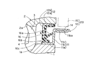
FIG. 4 shows an enlarged view of the
The
The first
第2の環状部材12は、上記シール部材9(図3)を構成する部材であり、第1の環状部材11の立板部11bに摺接するサイドリップ16aと円筒部11aに摺接するラジアルリップ16b,16cとを一体に有する。これらリップ16a〜16cは、第2の環状部材12に加硫接着された弾性部材16の一部として設けられている。これらリップ16a〜16cの枚数は任意で良いが、図4の例では、1枚のサイドリップ16aと、軸方向の内外に位置する2枚のラジアルリップ16c,16bとを設けている。第2の環状部材12は、固定側部材である外方部材2との嵌合部に弾性部材16を抱持したものとしてある。すなわち、弾性部材16は、円筒部12aの内径面から先端部外径までを覆う先端覆い部16dを有するものとし、この先端覆い部16dが、第2の環状部材12と外方部材2との嵌合部に介在する。
The second
第2の環状部材12の円筒部12aと第1の環状部材11の立板部11bの先端とは僅かな径方向隙間をもって対峙させ、その隙間でラビリンスシール17を構成している。
The
この構成の車輪用軸受によると、車輪と共に回転する内方部材1の回転が、この内方部材1に取付けられた磁気エンコーダ10を介して、磁気センサ15で検出され、車輪回転速度が検出される。
磁気エンコーダ10は、シール装置5の構成要素としたため、部品点数を増やすことなく、車輪の回転を検出することができる。車輪用軸受は、一般に路面の環境下にさらされた状態となり、磁気エンコーダ10とこれに対面させる磁気センサとの間に砂粒等の粒子が噛み込むことがあるが、上記のように磁気エンコーダ10の磁性部材14は合成樹脂塗料からなるものであって硬質であるため、磁性部材14の表面の摩耗損傷は従来の弾性体性のものに比べて大幅に低減される。また、車輪用軸受5における軸受端部の空間は、周辺に等速ジョイント7や軸受支持部材(図示せず)があって限られた狭い空間となるが、磁気エンコーダ10の磁性部材14が上記のように薄肉化できるため、回転検出装置20の配置が容易になる。
内外の部材1,2間のシールについては、第2の環状部材12に設けられた各シールリップ16a〜16cの摺接と、第2の環状部材12の円筒部12aに第1の環状部材11の立板部11bの先端が僅かな径方向隙間で対峙することで構成されるラビリンスシール17とで得られる。
According to the wheel bearing of this configuration, the rotation of the
Since the
As for the seal between the inner and
なお、上記実施形態において、磁気エンコーダ10の環状部材11は、鋼板プレス成形品製としたが、図6に示すように、磁気エンコーダ10の環状部材11は、鋼材等の削り出し品からなるものとしても良い。同図の例の環状部材11は立板部11bの溝部11baを切削加工溝としている。
また、磁気エンコーダ10を軸受のシール装置5の構成要素とする場合等において、磁性部材14を、前記各実施形態とは逆に軸受に対して内向きに設けても良い。その場合、環状部材11は非磁性体製のものとすることが好ましい。
さらに、磁気エンコーダ10は、前記各実施形態のように磁性部材14を軸方向に向けたものに限らず、例えば図7に示すように、径方向に向けて設けても良い。同図の例は、シール装置5のスリンガとなる環状部材11から軸方向の外側へ延びる第2の円筒部11cを設け、第2の円筒部11cの外周に磁性部材14を設けている。この場合、磁気センサ15は、磁性部材14に対して径方向に対面配置する。
In the above embodiment, the
Further, when the
Further, the
また、この発明の磁気エンコーダは、軸受のシール装置5の構成部品とするものに限らず、単独で回転検出に利用することができる。例えば、図1の実施形態における磁気エンコーダ10を、シール装置5は別に軸受に設けても良く、また図8に示すように、磁性部材14が径方向に向く磁気エンコーダ10を、円筒状の環状部材11の外径面に磁性部材14を設けた構成のものとし、車輪用軸受における外方部材2Aの外径面に嵌合させて設けても良い。同図の車輪用軸受は、内方部材1Aおよび外方部材2Aのうちの外方部材2Aを回転側の部材とし、外方部材2Aに車輪取付フランジ26を設けたものである。シール装置14は、磁気エンコーダ10とは別に軸受に設けられる。外方部材2Aは一対の分割内輪18A,19Aからなる。
Further, the magnetic encoder of the present invention is not limited to a component of the
1…内方部材
2…外方部材
1A…内方部材
2A…外方部材
3…転動体
5…シール装置
10…磁気エンコーダ
11…環状部材
14…磁性部材
15…磁気センサ
20…回転検出装置
DESCRIPTION OF
Claims (2)
前記磁性部材が、熱可塑性樹脂にフェライト系の磁性粉体を混入したものであることを特徴とする磁気エンコーダ。 In a magnetic encoder comprising an annular member made of metal and a magnetic member provided on the annular member along the circumferential direction and magnetized in multiple directions in the circumferential direction,
A magnetic encoder, wherein the magnetic member is a thermoplastic resin in which ferrite magnetic powder is mixed.
A wheel bearing comprising: an inner member and an outer member; a double row rolling element housed between the inner and outer members; and a seal device for sealing an end annular space between the inner and outer members. A wheel bearing in which the magnetic encoder according to 1 is a component of the sealing device.
Priority Applications (1)
| Application Number | Priority Date | Filing Date | Title |
|---|---|---|---|
| JP2006233176A JP2007033455A (en) | 2006-08-30 | 2006-08-30 | Magnetic encoder and wheel bearing having it |
Applications Claiming Priority (1)
| Application Number | Priority Date | Filing Date | Title |
|---|---|---|---|
| JP2006233176A JP2007033455A (en) | 2006-08-30 | 2006-08-30 | Magnetic encoder and wheel bearing having it |
Related Parent Applications (1)
| Application Number | Title | Priority Date | Filing Date |
|---|---|---|---|
| JP2001223876A Division JP4024496B2 (en) | 2001-07-25 | 2001-07-25 | Magnetic encoder and wheel bearing provided with the same |
Related Child Applications (1)
| Application Number | Title | Priority Date | Filing Date |
|---|---|---|---|
| JP2007311017A Division JP2008083064A (en) | 2007-11-30 | 2007-11-30 | Bearing for wheel |
Publications (1)
| Publication Number | Publication Date |
|---|---|
| JP2007033455A true JP2007033455A (en) | 2007-02-08 |
Family
ID=37792863
Family Applications (1)
| Application Number | Title | Priority Date | Filing Date |
|---|---|---|---|
| JP2006233176A Pending JP2007033455A (en) | 2006-08-30 | 2006-08-30 | Magnetic encoder and wheel bearing having it |
Country Status (1)
| Country | Link |
|---|---|
| JP (1) | JP2007033455A (en) |
Cited By (10)
| Publication number | Priority date | Publication date | Assignee | Title |
|---|---|---|---|---|
| WO2008136169A1 (en) * | 2007-04-13 | 2008-11-13 | Ntn Corporation | Bearing device adapted for use in wheel and having rotational speed detector |
| WO2015008622A1 (en) * | 2013-07-16 | 2015-01-22 | Ntn株式会社 | Magnetic encoder device and rotation detection device |
| JP2015021741A (en) * | 2013-07-16 | 2015-02-02 | Ntn株式会社 | Magnetic encoder device and rotation detection device |
| JP2015078889A (en) * | 2013-10-16 | 2015-04-23 | Ntn株式会社 | Magnetic encoder device and rotation detection device |
| JP2017106514A (en) * | 2015-12-08 | 2017-06-15 | 内山工業株式会社 | Sealing device |
| DE102007050256B4 (en) | 2007-10-20 | 2019-05-23 | Schaeffler Technologies AG & Co. KG | Bearing component with an encoder element for indicating a position or movement of the bearing component |
| US10585964B2 (en) | 2007-02-21 | 2020-03-10 | Advanced Custom Engineered Systems & Equipment Co. | System for monitoring a container |
| US10635864B2 (en) | 2013-05-15 | 2020-04-28 | Advanced Custom Engineered Systems & Equipment Company | Method for deploying large numbers of waste containers in a waste collection system |
| US11074557B2 (en) | 2016-03-31 | 2021-07-27 | Advanced Custom Engineered Systems & Equipment Co. | Systems and method for interrogating, publishing and analyzing information related to a waste hauling vehicle |
| US11267646B2 (en) | 2008-11-07 | 2022-03-08 | Advanced Custom Engineered Systems & Equipment Co. | Method and apparatus for monitoring waste removal and administration |
-
2006
- 2006-08-30 JP JP2006233176A patent/JP2007033455A/en active Pending
Cited By (20)
| Publication number | Priority date | Publication date | Assignee | Title |
|---|---|---|---|---|
| US10585964B2 (en) | 2007-02-21 | 2020-03-10 | Advanced Custom Engineered Systems & Equipment Co. | System for monitoring a container |
| US12373510B2 (en) | 2007-02-21 | 2025-07-29 | Advanced Custom Engineered Systems & Equipment Co. | Waste container monitoring system |
| US11907318B2 (en) | 2007-02-21 | 2024-02-20 | Advanced Custom Engineered Systems & Equipment Co. | Waste container monitoring system |
| US11461424B2 (en) | 2007-02-21 | 2022-10-04 | Advanced Custom Engineered Systems & Equipment Co. | Waste container monitoring system |
| US11017049B2 (en) | 2007-02-21 | 2021-05-25 | Advanced Custom Engineered Systems & Equipment Co. | Waste container monitoring system |
| WO2008136169A1 (en) * | 2007-04-13 | 2008-11-13 | Ntn Corporation | Bearing device adapted for use in wheel and having rotational speed detector |
| DE102007050256B4 (en) | 2007-10-20 | 2019-05-23 | Schaeffler Technologies AG & Co. KG | Bearing component with an encoder element for indicating a position or movement of the bearing component |
| US11286108B2 (en) | 2008-11-07 | 2022-03-29 | Advanced Custom Engineered Systems & Equipment Co. | Method and apparatus for monitoring waste removal and administration |
| US11767164B2 (en) | 2008-11-07 | 2023-09-26 | Advanced Custom Engineered Systems & Equipment Co. | Method and apparatus for monitoring waste removal and administration |
| US11267646B2 (en) | 2008-11-07 | 2022-03-08 | Advanced Custom Engineered Systems & Equipment Co. | Method and apparatus for monitoring waste removal and administration |
| US10635864B2 (en) | 2013-05-15 | 2020-04-28 | Advanced Custom Engineered Systems & Equipment Company | Method for deploying large numbers of waste containers in a waste collection system |
| US11640575B2 (en) | 2013-05-15 | 2023-05-02 | Advanced Custom Engineered Systems & Equipment Co. | Method for deploying large numbers of waste containers in a waste collection system |
| US11144736B2 (en) | 2013-05-15 | 2021-10-12 | Advanced Custom Engineered Systems & Equipment Co. | Method for deploying large numbers of waste containers in a waste collection system |
| US9976874B2 (en) | 2013-07-16 | 2018-05-22 | Ntn Corporation | Magnetic encoder device and rotation detection device |
| JP2015021741A (en) * | 2013-07-16 | 2015-02-02 | Ntn株式会社 | Magnetic encoder device and rotation detection device |
| WO2015008622A1 (en) * | 2013-07-16 | 2015-01-22 | Ntn株式会社 | Magnetic encoder device and rotation detection device |
| JP2015078889A (en) * | 2013-10-16 | 2015-04-23 | Ntn株式会社 | Magnetic encoder device and rotation detection device |
| JP2017106514A (en) * | 2015-12-08 | 2017-06-15 | 内山工業株式会社 | Sealing device |
| US11074557B2 (en) | 2016-03-31 | 2021-07-27 | Advanced Custom Engineered Systems & Equipment Co. | Systems and method for interrogating, publishing and analyzing information related to a waste hauling vehicle |
| US11727363B2 (en) | 2016-03-31 | 2023-08-15 | Advanced Custom Engineered Systems & Equipment Company | Systems and method for interrogating, publishing and analyzing information related to a waste hauling vehicle |
Similar Documents
| Publication | Publication Date | Title |
|---|---|---|
| US7350976B2 (en) | Bearing for a wheel of vehicle | |
| CN101836120A (en) | Encoder element for displaying an adjustment or movement of a bearing constituent | |
| JP4024496B2 (en) | Magnetic encoder and wheel bearing provided with the same | |
| CN106895071A (en) | For the sealing device of bearing-hub assembly | |
| JP2004270872A (en) | Bearing for wheel | |
| JP2007033455A (en) | Magnetic encoder and wheel bearing having it | |
| JP2001065704A (en) | Sealing device | |
| JP2004037441A (en) | Magnetic encoder and wheel bearing using it | |
| US8054064B2 (en) | Sensor holder with a wheel bearing apparatus incorporated with a wheel speed detecting apparatus including an annular fitting member in the sensor holder and a seal positioned between the annular fitting member and an outer circumference of an inner ring | |
| JP2008083064A (en) | Bearing for wheel | |
| JP4024823B2 (en) | Magnetic encoder and wheel bearing provided with the same | |
| JP4024821B2 (en) | Magnetic encoder and wheel bearing provided with the same | |
| JP4024822B2 (en) | Magnetic encoder and wheel bearing provided with the same | |
| JP2002328133A (en) | Bearing for wheel with revolution speed detector | |
| JP2004084925A (en) | Magnetic encoder and wheel bearing provided with encoder | |
| JP2004085534A (en) | Magnetic encoder and wheel bearing having the same | |
| JP2006064145A (en) | Bearing device for wheel | |
| JP4361003B2 (en) | Wheel bearing | |
| EP1983306B1 (en) | Rotor for rotary encoder and rolling bearing for wheel having same | |
| JP4498330B2 (en) | Magnetic encoder and wheel bearing provided with the same | |
| JP3881359B2 (en) | Bearing seal device | |
| JP2004183769A (en) | Bearing device for wheel | |
| JP2006161990A (en) | Bearing for wheel | |
| JP5002992B2 (en) | Rolling bearing with encoder | |
| JP4704002B2 (en) | Magnetic encoder and wheel bearing device provided with the same |
Legal Events
| Date | Code | Title | Description |
|---|---|---|---|
| A621 | Written request for application examination |
Free format text: JAPANESE INTERMEDIATE CODE: A621 Effective date: 20070309 |
|
| A871 | Explanation of circumstances concerning accelerated examination |
Free format text: JAPANESE INTERMEDIATE CODE: A871 Effective date: 20070309 |
|
| A975 | Report on accelerated examination |
Free format text: JAPANESE INTERMEDIATE CODE: A971005 Effective date: 20070413 |
|
| A131 | Notification of reasons for refusal |
Free format text: JAPANESE INTERMEDIATE CODE: A131 Effective date: 20070424 |
|
| A521 | Written amendment |
Free format text: JAPANESE INTERMEDIATE CODE: A523 Effective date: 20070622 |
|
| A02 | Decision of refusal |
Free format text: JAPANESE INTERMEDIATE CODE: A02 Effective date: 20071002 |
|
| A521 | Written amendment |
Free format text: JAPANESE INTERMEDIATE CODE: A523 Effective date: 20071130 |
|
| A911 | Transfer of reconsideration by examiner before appeal (zenchi) |
Free format text: JAPANESE INTERMEDIATE CODE: A911 Effective date: 20071207 |
|
| A912 | Removal of reconsideration by examiner before appeal (zenchi) |
Free format text: JAPANESE INTERMEDIATE CODE: A912 Effective date: 20071228 |