JP2007031663A - Film forming composition, insulating film formed using the same, and electronic device - Google Patents
Film forming composition, insulating film formed using the same, and electronic device Download PDFInfo
- Publication number
- JP2007031663A JP2007031663A JP2005220859A JP2005220859A JP2007031663A JP 2007031663 A JP2007031663 A JP 2007031663A JP 2005220859 A JP2005220859 A JP 2005220859A JP 2005220859 A JP2005220859 A JP 2005220859A JP 2007031663 A JP2007031663 A JP 2007031663A
- Authority
- JP
- Japan
- Prior art keywords
- film
- group
- forming composition
- insulating film
- cage structure
- Prior art date
- Legal status (The legal status is an assumption and is not a legal conclusion. Google has not performed a legal analysis and makes no representation as to the accuracy of the status listed.)
- Abandoned
Links
Landscapes
- Compositions Of Macromolecular Compounds (AREA)
- Formation Of Insulating Films (AREA)
Abstract
Description
本発明は膜形成用組成物に関し、さらに詳しくは電子デバイスなどに用いられる誘電率、機械強度等の膜特性が良好な絶縁膜形成用組成物に関し、さらには該組成物を用いて得られる絶縁膜を有する電子デバイスに関する。 The present invention relates to a film-forming composition, and more particularly, to an insulating film-forming composition having good film properties such as dielectric constant and mechanical strength used for electronic devices, and further, an insulation obtained using the composition. The present invention relates to an electronic device having a film.
近年、電子材料分野においては、高集積化、多機能化、高性能化の進行に伴い、回路抵抗や配線間のコンデンサー容量が増大し、消費電力や遅延時間の増大を招いている。中でも、遅延時間の増大は、デバイスの信号スピードの低下やクロストークの発生の大きな要因となるため、この遅延時間を減少させてデバイスの高速化を図るべく、寄生抵抗や寄生容量の低減が求められている。この寄生容量を低減するための具体策の一つとして、配線の周辺を低誘電性の層間絶縁膜で被覆することが試みられている。また、層間絶縁膜には、実装基板製造時の薄膜形成工程やチップ接続、ピン付け等の後工程に耐え得る、優れた耐熱性やウェットプロセスに耐え得る耐薬品性が求められている。さらに、近年は、Al配線から低抵抗のCu配線が導入されつつあり、これに伴い、CMP(ケミカルメカニカルポリッシング)による平坦化が一般的となっており、このプロセスに耐え得る高い機械的強度が求められている。 In recent years, in the field of electronic materials, with the progress of higher integration, more functions, and higher performance, circuit resistance and capacitor capacity between wirings have increased, leading to an increase in power consumption and delay time. In particular, an increase in delay time is a major factor in reducing the signal speed of the device and the occurrence of crosstalk. Therefore, in order to reduce the delay time and speed up the device, it is necessary to reduce parasitic resistance and parasitic capacitance. It has been. As a specific measure for reducing this parasitic capacitance, an attempt has been made to cover the periphery of the wiring with a low dielectric interlayer insulating film. In addition, the interlayer insulating film is required to have excellent heat resistance and chemical resistance that can withstand a subsequent process such as a thin film formation process, chip connection, and pinning during manufacturing of a mounting substrate. Furthermore, in recent years, low resistance Cu wiring is being introduced from Al wiring, and along with this, planarization by CMP (Chemical Mechanical Polishing) has become common, and high mechanical strength that can withstand this process is high. It has been demanded.
高耐熱性の絶縁膜として、ポリベンゾオキサゾール、ポリイミドが広く知られているが、極性の高いN原子を含むため、低誘電性、低吸湿性、耐久性および耐加水分解性の面では、満足なものは得られていない。
また、有機ポリマーは概して有機溶剤への溶解性の不十分なものが多く、塗布液中での析出、絶縁膜中でのブツ発生の抑制が重要な課題となっているが、溶解性を向上させるためにポリマー主鎖を折れ曲がり構造にするとガラス転移点の低下、耐熱性の低下が弊害となりこれらを両立することは容易ではない。
また、ポリアリーレンエーテルを基本主鎖とする高耐熱性樹脂が知られており(特許文献1)、比誘電率は2.6〜2.7の範囲である。しかし、高速デバイスを実現するためには更なる低誘電率化が望まれている。
Polybenzoxazole and polyimide are widely known as highly heat-resistant insulating films, but because they contain highly polar N atoms, they are satisfactory in terms of low dielectric properties, low moisture absorption, durability, and hydrolysis resistance. Nothing has been obtained.
In addition, many organic polymers are generally poorly soluble in organic solvents, and it is an important issue to suppress precipitation in coating solutions and the generation of bumps in insulating films. Therefore, if the polymer main chain is bent to have a bent structure, the glass transition point and the heat resistance are adversely affected, and it is not easy to achieve both.
Further, a highly heat-resistant resin having a polyarylene ether as a basic main chain is known (Patent Document 1), and the relative dielectric constant is in the range of 2.6 to 2.7. However, in order to realize a high-speed device, further reduction of the dielectric constant is desired.
また、更なる低誘電率化が進むと絶縁膜の表面酸化に伴う吸湿の問題も顕在化する。絶縁膜の化学構造が低吸湿性に優れたものであったとしても、成膜工程の雰囲気に含まれる非常に微量な水分、非常に微量な酸素が絶縁膜に吸着し、その後の加熱工程においてこれらの水、酸素による表面酸化反応が起こって絶縁膜の表面にわずかに水酸基が生成する。水酸基はわずかな量であっても雰囲気中の水を多量に引き寄せて水和する性質があるため、吸湿性を増加させる。絶縁膜に含まれる水分は、絶縁膜の誘電率の増加、配線構造作成時のバリアメタルの酸化、剥れなどを引き起こすことが知られており、絶縁膜表面の吸湿性を抑制する為に水酸基を除去、または不活性化する技術が必要とされている。かご型化合物を有する低誘電率材料としては芳香族骨格にかご型化合物を付加した例がある(特許文献2)。上記に示した成膜工程における水酸基の発生は考慮しておらず低吸湿性の点で問題がある。有機系膜の表面に存在する水酸基に注目した例としてはダイヤモンド粒子表面に存在する水酸基を架橋分子で連結することを試みた例がある(特許文献3)。この技術では機械強度の点では優れたものを得ることができるが、粒子同士の架橋を行う為に粒子表面に水酸基が極めて多数存在している必要がある。そのために架橋後にも多数の水酸基が残存し、吸湿性の点で問題がある。 Further, when the dielectric constant is further reduced, the problem of moisture absorption accompanying the surface oxidation of the insulating film becomes obvious. Even if the chemical structure of the insulating film is excellent in low hygroscopicity, a very small amount of moisture and very small amount of oxygen contained in the atmosphere of the film forming process are adsorbed on the insulating film, and in the subsequent heating process The surface oxidation reaction by these water and oxygen occurs, and a slight hydroxyl group is generated on the surface of the insulating film. Even if the amount of the hydroxyl group is small, it has the property of attracting a large amount of water in the atmosphere and hydrating it, thereby increasing the hygroscopicity. Moisture contained in the insulating film is known to cause an increase in the dielectric constant of the insulating film, oxidation of the barrier metal during wiring structure creation, peeling, etc. In order to suppress the hygroscopicity of the insulating film surface, There is a need for a technique to remove or inactivate. As a low dielectric constant material having a cage compound, there is an example in which a cage compound is added to an aromatic skeleton (Patent Document 2). The generation of hydroxyl groups in the film forming process described above is not taken into consideration, and there is a problem in terms of low hygroscopicity. As an example paying attention to the hydroxyl group which exists in the surface of an organic type film, there exists an example which tried to connect the hydroxyl group which exists in the diamond particle surface with a bridge | crosslinking molecule | numerator (patent document 3). In this technique, an excellent material in terms of mechanical strength can be obtained. However, in order to perform cross-linking between particles, it is necessary that a very large number of hydroxyl groups exist on the particle surface. Therefore, a large number of hydroxyl groups remain after crosslinking, which is problematic in terms of hygroscopicity.
本発明は、上記問題点を解決するための膜形成用組成物に関し、さらに詳しくは電子デバイスなどに用いられる誘電率、機械強度等の膜特性が良好な絶縁膜形成用組成物に関し、さらには該組成物を用いて得られる絶縁膜およびそれを有する電子デバイスに関する。 The present invention relates to a film-forming composition for solving the above-described problems, and more particularly to an insulating film-forming composition having good film properties such as dielectric constant and mechanical strength used for electronic devices, etc. The present invention relates to an insulating film obtained using the composition and an electronic device having the insulating film.
上記課題が下記の<1>〜<12>の構成により解決されることを見出した。
<1>
カゴ型構造を有する化合物と水酸基と反応可能な化学種を含むことを特徴とする膜形成用組成物。
<2>
水酸基と反応可能な化学種が水酸基と反応可能な官能基を2つ以上有することを特徴とする上記<1>に記載の膜形成用組成物。
<3>
水酸基と反応可能な官能基を有する分子が環状構造を有することを特徴とする上記<1>および<2>に記載の膜形成用組成物。
It has been found that the above problems are solved by the following <1> to <12> configurations.
<1>
A film-forming composition comprising a compound having a cage structure and a chemical species capable of reacting with a hydroxyl group.
<2>
The film forming composition as described in <1> above, wherein the chemical species capable of reacting with a hydroxyl group has two or more functional groups capable of reacting with a hydroxyl group.
<3>
The film forming composition as described in <1> or <2> above, wherein the molecule having a functional group capable of reacting with a hydroxyl group has a cyclic structure.
<4>
カゴ型構造が飽和炭化水素構造であることを特徴とする上記<1>〜<3>のいずれかに記載の膜形成用組成物。
<5>
膜形成用組成物に含まれる全固形分中の総炭素数に占めるカゴ型構造の総炭素数の比率が30%以上であることを特徴とする上記<1>〜<4>のいずれかに記載の膜形成用組成物。
<6>
カゴ型構造がアダマンタン構造であることを特徴とする上記<1>〜<5>のいずれかに記載の膜形成用組成物。
<4>
The film-forming composition as described in any one of <1> to <3> above, wherein the cage structure is a saturated hydrocarbon structure.
<5>
Any of <1> to <4> above, wherein the ratio of the total carbon number of the cage structure to the total carbon number in the total solid content contained in the film-forming composition is 30% or more The composition for film formation as described.
<6>
The film-forming composition as described in any one of <1> to <5> above, wherein the cage structure is an adamantane structure.
<7>
カゴ型構造がジアマンタン構造であることを特徴とする上記<1>〜<6>のいずれかに記載の膜形成用組成物。
<8>
カゴ型構造を有する化合物が下記式(I)で表される少なくとも一つの化合物の重合体である上記<7>に記載の膜形成用組成物。
<7>
The film-forming composition as described in any one of <1> to <6> above, wherein the cage structure is a diamantane structure.
<8>
The film forming composition according to <7>, wherein the compound having a cage structure is a polymer of at least one compound represented by the following formula (I).
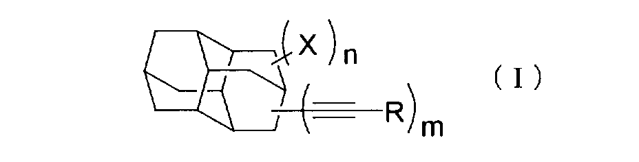
式(I)中、
Rは水素原子、アルキル基、アルケニル基、アルキニル基、アリール基またはシリル基を表す。
mは1〜14の整数を表す。
Xはハロゲン原子、アルキル基、アルケニル基、アリール基またはシリル基を表す。
nは0〜13の整数を表す。
In formula (I),
R represents a hydrogen atom, an alkyl group, an alkenyl group, an alkynyl group, an aryl group or a silyl group.
m represents an integer of 1 to 14.
X represents a halogen atom, an alkyl group, an alkenyl group, an aryl group or a silyl group.
n represents an integer of 0 to 13.
<9>
カゴ型構造を有する化合物が窒素原子を有さないことを特徴とする上記<1>〜<8>のいずれかに記載の膜形成用組成物。
<10>
有機溶剤を含む上記<1>〜<9>のいずれかに記載の膜形成用組成物。
<11>
上記<10>に記載の膜形成用組成物を用いて形成した絶縁膜。
<12>
上記<11>に記載の絶縁膜を有する電子デバイス。
<9>
The film-forming composition according to any one of <1> to <8>, wherein the compound having a cage structure does not have a nitrogen atom.
<10>
The film forming composition according to any one of <1> to <9>, which contains an organic solvent.
<11>
An insulating film formed using the film forming composition as described in <10> above.
<12>
The electronic device which has an insulating film as described in said <11>.
本発明の膜形成用組成物により形成した絶縁膜は低吸湿性、誘電率、機械強度等の膜特性が良好なため、電子デバイスなどにおける層間絶縁膜として利用できる。 Since the insulating film formed from the film forming composition of the present invention has good film properties such as low hygroscopicity, dielectric constant, and mechanical strength, it can be used as an interlayer insulating film in electronic devices and the like.
以下、本発明を詳細に説明する。 Hereinafter, the present invention will be described in detail.
<カゴ型構造を有する化合物>
本発明で述べる「カゴ型構造」とは、共有結合した原子で形成された複数の環によって容積が定まり、容積内に位置する点は環を通過せずには容積から離れることができないような分子を指す。例えば、アダマンタン構造はカゴ型構造と考えられる。対照的にノルボルナン(ビシクロ[2,2,1]ヘプタン)などの単一架橋を有する環状構造は、単一架橋した環状化合物の環が容積を定めないことから、カゴ型構造とは考えられない。
<Compound having a cage structure>
The “cage structure” described in the present invention is such that the volume is determined by a plurality of rings formed of covalently bonded atoms, and a point located within the volume cannot be separated from the volume without passing through the ring. Refers to a molecule. For example, an adamantane structure is considered a cage structure. In contrast, a cyclic structure having a single bridge such as norbornane (bicyclo [2,2,1] heptane) is not considered a cage structure because the ring of a single bridged cyclic compound does not define volume. .
本発明のカゴ型構造の総炭素数は、好ましくは10〜30個、より好ましくは10〜18個、特に好ましくは14個の炭素原子で構成される。
ここでいう炭素原子にはカゴ型構造に置換した連結基や置換基の炭素原子を含めない。例えば、1−メチルアダマンタンは10個の炭素原子で構成され、1−エチルジアマンタンは14個の炭素原子で構成されるものとする。
The total number of carbon atoms in the cage structure of the present invention is preferably 10 to 30, more preferably 10 to 18, and particularly preferably 14 carbon atoms.
The carbon atom here does not include a linking group substituted with a cage structure or a carbon atom of the substituent. For example, 1-methyladamantane is composed of 10 carbon atoms, and 1-ethyldiamantane is composed of 14 carbon atoms.
本発明のカゴ型構造を有する化合物は飽和炭化水素であることが好ましく、好ましい例としては高い耐熱性を有している点でダイヤモンド類似構造のアダマンタン、ジアマンタン、トリアマンタン、テトラマンタン、ドデカヘドラン等が挙げられ、より好ましい例としてはアダマンタン、ジアマンタン、トリアマンタンが挙げられ、特に好ましい例としてはより低い誘電率が得られ、合成が容易である点でジアマンタンが挙げられる。 The compound having a cage structure of the present invention is preferably a saturated hydrocarbon, and preferable examples thereof include diamond-like structures such as adamantane, diamantane, triamantane, tetramantane, dodecahedran, etc. because of high heat resistance. More preferred examples include adamantane, diamantane, and triamantane, and particularly preferred examples include diamantane in that a lower dielectric constant is obtained and synthesis is easy.
本発明におけるカゴ型構造は1つ以上の置換基を有していても良く、置換基の例としては、ハロゲン原子(フッ素原子、クロル原子、臭素原子、または沃素原子)、炭素数1〜10の直鎖、分岐、環状のアルキル基(メチル、t−ブチル、シクロペンチル、シクロヘキシル等)、炭素数2〜10のアルケニル基(ビニル、プロペニル等)、炭素数2〜10のアルキニル基(エチニル、フェニルエチニル等)、炭素数6〜20のアリール基(フェニル、1−ナフチル、2−ナフチル等)、炭素数2〜10のアシル基(ベンゾイル等)、炭素数6〜20のアリールオキシ基(フェノキシ等)、炭素数6〜20のアリールスルホニル基(フェニルスルホニル等)、ニトロ基、シアノ基、シリル基(トリエトキシシリル、メチルジエトキシシリル、トリビニルシリル等)等が挙げられる。この中で好ましい置換基はフッ素原子、臭素原子、炭素数1〜5の直鎖、分岐、環状のアルキル基、炭素数2〜5のアルケニル基、炭素数2〜5のアルキニル基、シリル基である。これらの置換基は
さらに別の置換基で置換されていてもよい。
The cage structure in the present invention may have one or more substituents. Examples of the substituent include a halogen atom (a fluorine atom, a chloro atom, a bromine atom, or an iodine atom), a carbon number of 1 to 10. Linear, branched and cyclic alkyl groups (methyl, t-butyl, cyclopentyl, cyclohexyl, etc.), alkenyl groups having 2 to 10 carbon atoms (vinyl, propenyl, etc.), alkynyl groups having 2 to 10 carbon atoms (ethynyl, phenyl) Ethynyl etc.), C6-C20 aryl groups (phenyl, 1-naphthyl, 2-naphthyl etc.), C2-C10 acyl groups (benzoyl etc.), C6-C20 aryloxy groups (phenoxy etc.) ), Arylsulfonyl groups having 6 to 20 carbon atoms (such as phenylsulfonyl), nitro groups, cyano groups, silyl groups (triethoxysilyl, methyldiethoxysilyl, Vinylsilyl etc.) and the like. Among these, preferred substituents are a fluorine atom, a bromine atom, a linear, branched or cyclic alkyl group having 1 to 5 carbon atoms, an alkenyl group having 2 to 5 carbon atoms, an alkynyl group having 2 to 5 carbon atoms, and a silyl group. is there. These substituents may be further substituted with another substituent.
本発明におけるカゴ型構造は1〜4価であることが好ましく、より好ましくは2〜3価であり、特に好ましくは2価である。このとき、カゴ型構造に結合する基は1価以上の置換基でも2価以上の連結基でも良い。ここで「価」とは結合手の数を意味する。 The cage structure in the present invention is preferably 1 to 4 valent, more preferably 2 to 3 valent, and particularly preferably 2 valent. At this time, the group bonded to the cage structure may be a monovalent or higher valent substituent or a divalent or higher linking group. Here, “valence” means the number of bonds.
本発明の「カゴ型構造を有する化合物」とは、低分子化合物であっても高分子化合物(たとえばポリマー)であっても良く、好ましいものはポリマーである。カゴ型構造を有する化合物がポリマーである場合、その質量平均分子量は好ましくは1000〜500000、より好ましくは5000〜300000、特に好ましくは10000〜200000である。カゴ型構造を有するポリマーは分子量分布を有する樹脂組成物として膜形成用組成物に含まれていても良い。カゴ型構造を有する化合物が低分子化合物である場合、その分子量は好ましくは3000以下、より好ましくは2000以下、特に好ましくは1000以下である。 The “compound having a cage structure” of the present invention may be a low molecular compound or a high molecular compound (for example, a polymer), and is preferably a polymer. When the compound having a cage structure is a polymer, the mass average molecular weight is preferably 1,000 to 500,000, more preferably 5,000 to 300,000, and particularly preferably 10,000 to 200,000. The polymer having a cage structure may be contained in the film forming composition as a resin composition having a molecular weight distribution. When the compound having a cage structure is a low molecular compound, the molecular weight is preferably 3000 or less, more preferably 2000 or less, and particularly preferably 1000 or less.
本発明においてカゴ型構造はポリマー主鎖に1価以上のペンダント基として組み込まれても良い。かご化合物が結合する好ましいポリマー主鎖としては、例えばポリ(アリーレン)、ポリ(アリーレンエーテル)、ポリ(エーテル)、ポリアセチレン等の共役不飽和結合鎖、ポリエチレン等が挙げられ、この中でも耐熱性が良好な点から、ポリ(アリーレンエーテル)、ポリアセチレンがより好ましい。 In the present invention, the cage structure may be incorporated into the polymer main chain as a monovalent or higher pendant group. Preferred polymer main chains to which the cage compound is bonded include, for example, conjugated unsaturated bond chains such as poly (arylene), poly (arylene ether), poly (ether), polyacetylene, polyethylene, etc. Among them, heat resistance is good. From these points, poly (arylene ether) and polyacetylene are more preferable.
本発明においてカゴ型構造がポリマー主鎖の一部となっていることも好ましい。すなわちポリマー主鎖の一部になっている場合には、本ポリマーからかご化合物を除去するとポリマー鎖が切断されることを意味する。この形態においては、カゴ型構造はカゴ構造間で直接単結合するかまたは適当な2価以上の連結基によって連結される。連結基の例としては例えば、−C(R11)(R12)−、−C(R13)=C(R14)−、−C≡C−、アリーレン基、−CO−、−O−、−SO2−、−N(R15)−、−Si(R16)(R17)−またはこれらを組み合わせた基が挙げられる。ここで、R11〜R17はそれぞれ独立に水素原子、アルキル基、アルケニル基、アルキニル基、アリール基、アルコキシ基を表す。これらの連結基は置換基で置換されていてもよく、例えば前述の置換基が好ましい例として挙げられる。
この中でより好ましい連結基は、−C(R11)(R12)−、−CH=CH−、−C≡C−、アリーレン基、−O−、−Si(R16)(R17)−またはこれらを組み合わせた基であり、特に好ましいものは、−CH=CH−、−C≡C−、−O−、−Si(R16)(R17)−またはこれらの組み合わせである。
In the present invention, the cage structure is also preferably a part of the polymer main chain. That is, when it is a part of the polymer main chain, it means that the polymer chain is cleaved when the cage compound is removed from the polymer. In this form, the cage structures are directly single-bonded between the cage structures or linked by a suitable divalent or higher linking group. Examples of the linking group include, for example, —C (R 11 ) (R 12 ) —, —C (R 13 ) ═C (R 14 ) —, —C≡C—, arylene group, —CO—, —O—. , —SO 2 —, —N (R 15 ) —, —Si (R 16 ) (R 17 ) —, or a combination thereof. Here, R 11 to R 17 each independently represent a hydrogen atom, an alkyl group, an alkenyl group, an alkynyl group, an aryl group, or an alkoxy group. These linking groups may be substituted with a substituent, and for example, the above-described substituents are preferable examples.
Among these, more preferred linking groups are —C (R 11 ) (R 12 ) —, —CH═CH—, —C≡C—, arylene group, —O—, —Si (R 16 ) (R 17 ). -Or a combination thereof, and particularly preferred are -CH = CH-, -C≡C-, -O-, -Si (R 16 ) (R 17 )-or a combination thereof.
本発明の「カゴ型構造を有する化合物」は、その分子内にカゴ型構造を1種でも2種以上含んでいても良い。 The “compound having a cage structure” of the present invention may contain one or more cage structures in the molecule.
以下に本発明の「カゴ型構造を有する化合物」の具体例を示すが、もちろん本発明はこれらに限定されない。以下において、nは正数を表す。 Specific examples of the “compound having a cage structure” of the present invention are shown below, but the present invention is of course not limited thereto. In the following, n represents a positive number.
本発明のカゴ型構造を有する化合物は下記式(I)で表される化合物の重合体であることが特に好ましい。 The compound having a cage structure of the present invention is particularly preferably a polymer of a compound represented by the following formula (I).
式(I)において、
Rは水素原子、アルキル基(好ましくは炭素数1〜10)、アルケニル基(好ましくは炭素数2〜10)、アルキニル基(好ましくは炭素数2〜10)、アリール基(好ましくは炭素数6〜20)またはシリル基(好ましくは炭素数0〜20)を表し、Rが水素原子以外の場合、Rはさらに別の置換基で置換されていてもよい。置換基としては例えばハロゲン原子(フッ素原子、クロル原子、臭素原子、または沃素原子)、アルキル基、アルケニル基、アルキニル基、アリール基、アシル基、アリールオキシ基、アリールスルホニル基、ニトロ基、シアノ基、シリル基等が挙げられる。Rは好ましくは水素原子、炭素数1〜10のアルキル基、炭素数6〜20のアリール基または炭素数0〜20のシリル基であり、より好ましくは水素原子または炭素数0〜10のシリル基である。
mは1〜14の整数を表し、好ましくは1〜4の整数であり、より好ましくは1〜3の整数であり、特に好ましくは2または3である。
In formula (I):
R represents a hydrogen atom, an alkyl group (preferably 1 to 10 carbon atoms), an alkenyl group (preferably 2 to 10 carbon atoms), an alkynyl group (preferably 2 to 10 carbon atoms), an aryl group (preferably 6 to 6 carbon atoms). 20) or a silyl group (preferably having 0 to 20 carbon atoms), and when R is other than a hydrogen atom, R may be further substituted with another substituent. Examples of the substituent include a halogen atom (fluorine atom, chloro atom, bromine atom, or iodine atom), alkyl group, alkenyl group, alkynyl group, aryl group, acyl group, aryloxy group, arylsulfonyl group, nitro group, cyano group. And a silyl group. R is preferably a hydrogen atom, an alkyl group having 1 to 10 carbon atoms, an aryl group having 6 to 20 carbon atoms or a silyl group having 0 to 20 carbon atoms, more preferably a hydrogen atom or a silyl group having 0 to 10 carbon atoms. It is.
m represents an integer of 1 to 14, preferably an integer of 1 to 4, more preferably an integer of 1 to 3, and particularly preferably 2 or 3.
Xはハロゲン原子、アルキル基(好ましくは炭素数1〜10)、アルケニル基(好ましくは炭素数2〜10)、アリール基(好ましくは炭素数6〜20)、シリル基(好ましくは炭素数0〜20)を表し、Xはさらに別の置換基で置換されていても良く、置換基の例として前述のものが挙げられる。Xは好ましくは、フッ素原子、塩素原子、臭素原子、炭素数1〜10のアルキル基、炭素数2〜10のアルケニル基、炭素数0〜20のシリル基であり、より好ましくは臭素原子、炭素数2〜4のアルケニル基、炭素数0〜10シリル基である。
nは0〜13の整数を表し、好ましくは0〜3の整数であり、より好ましくは0〜2の整数であり、特に好ましくは0または1である。
X represents a halogen atom, an alkyl group (preferably 1 to 10 carbon atoms), an alkenyl group (preferably 2 to 10 carbon atoms), an aryl group (preferably 6 to 20 carbon atoms), a silyl group (preferably 0 to 0 carbon atoms). 20), X may be further substituted with another substituent, and examples of the substituent include those described above. X is preferably a fluorine atom, a chlorine atom, a bromine atom, an alkyl group having 1 to 10 carbon atoms, an alkenyl group having 2 to 10 carbon atoms, or a silyl group having 0 to 20 carbon atoms, more preferably a bromine atom or carbon. An alkenyl group having 2 to 4 carbon atoms, and a silyl group having 0 to 10 carbon atoms.
n represents an integer of 0 to 13, preferably an integer of 0 to 3, more preferably an integer of 0 to 2, and particularly preferably 0 or 1.
式(I)で表される化合物の最適な重合反応条件は有機溶剤中で、好ましくは内温0℃〜220℃、より好ましくは50℃〜210℃、特に好ましくは100℃〜200℃で、好ましくは1〜50時間、より好ましくは2〜20時間、3〜10時間で行うことが好ましい。所望により、パラジウム、ニッケル、タングステン、モリブデン等の金属触媒を用いてもよい。
重合したポリマーの質量平均分子量の好ましい範囲は1000〜500000、より好ましくは5000〜300000、特に好ましくは10000〜200000である。
Optimum polymerization reaction conditions for the compound represented by the formula (I) are in an organic solvent, preferably an internal temperature of 0 ° C to 220 ° C, more preferably 50 ° C to 210 ° C, and particularly preferably 100 ° C to 200 ° C. It is preferably performed for 1 to 50 hours, more preferably 2 to 20 hours and 3 to 10 hours. If desired, a metal catalyst such as palladium, nickel, tungsten, or molybdenum may be used.
The preferable range of the weight average molecular weight of the polymerized polymer is 1000 to 500000, more preferably 5000 to 300000, and particularly preferably 10000 to 200000.
式(I)で表される化合物の具体例を以下に示す。 Specific examples of the compound represented by the formula (I) are shown below.
本発明の化合物は熱により他の分子と共有結合を形成する反応性基を有していることが好ましい。このような反応性基としては、特に限定されないが例えば環化付加反応、ラジカル重合反応を起こす置換基が好ましく利用できる。例えば、2重結合を有する基(ビニル基、アリル基等)、3重結合を有する基(エチニル基、フェニルエチニル基等)、ディールスアルダー反応を起こすためのジエン基、ジエノフィル基の組み合わせ等が有効であり、特にエチニル基とフェニルエチニル基が有効である。 The compound of the present invention preferably has a reactive group that forms a covalent bond with other molecules by heat. Such a reactive group is not particularly limited, and for example, a substituent that causes a cycloaddition reaction or a radical polymerization reaction can be preferably used. For example, a group having a double bond (vinyl group, allyl group, etc.), a group having a triple bond (ethynyl group, phenylethynyl group, etc.), a combination of a diene group or a dienophile group for causing a Diels-Alder reaction is effective. In particular, an ethynyl group and a phenylethynyl group are effective.
また、本発明のカゴ型構造を有する化合物には、モル分極率を高めたり絶縁膜の吸湿性の原因となる窒素原子は誘電率を高くする働きがあるため含まないことが好ましい。特に、ポリイミド化合物では充分に低い誘電率が得られないため、本願のカゴ型構造を有する化合物は、ポリイミド以外の化合物、即ちポリイミド結合、アミド結合を有しない化合物であることが好ましい。 Further, the compound having a cage structure of the present invention preferably does not contain nitrogen atoms that increase the molar polarizability or cause the hygroscopicity of the insulating film to increase the dielectric constant. In particular, since a sufficiently low dielectric constant cannot be obtained with a polyimide compound, the compound having a cage structure of the present application is preferably a compound other than polyimide, that is, a compound having no polyimide bond or amide bond.
本発明の組成物より形成した絶縁膜に良好な特性(誘電率、機械強度)を付与する観点から、膜形成用組成物に含まれる全固形分中の総炭素数に占めるカゴ型構造の総炭素数の比率は30%以上であることが好ましく、より好ましくは50〜95%、さらに好ましくは60%〜90%である。ここで、膜形成用組成物に含まれる全固形分とは、この塗布液により得られる絶縁膜を構成する全固形分に相当するものである。尚、発泡剤のように絶縁膜形成後に絶縁膜中に残らないものは固形分に含めない。 From the viewpoint of imparting good characteristics (dielectric constant, mechanical strength) to the insulating film formed from the composition of the present invention, the total of the cage structure occupying the total number of carbons in the total solid content contained in the film-forming composition. The carbon number ratio is preferably 30% or more, more preferably 50 to 95%, and still more preferably 60% to 90%. Here, the total solid content contained in the film-forming composition corresponds to the total solid content constituting the insulating film obtained by this coating solution. In addition, what does not remain in an insulating film after insulating film formation like a foaming agent is not included in solid content.
<水酸基と反応可能な化学種>
本発明で述べる「水酸基と反応可能な化学種」とは水素ラジカル、水素イオン、水素分子など脱水反応を起こして水酸基そのものを除去する化学種と、Si−OH基、Si−H基、Si−X(Xはハロゲン元素)、アルコキシシリル基、Si−N結合、Si−O−Si結合、C−OH基、Si−OH基、COOH基、エステル基など水酸基と反応可能な官能基を有し、絶縁膜中の水酸基と反応し化学結合を形成しうる化合物の両方を含む。
水酸基と反応可能な官能基は水酸基と反応可能な化学種内に一つあれば本発明の効果は得られるが、より好ましくは2つ以上あることが好ましく、特に好ましくは3つ以上である。また、水酸基と反応可能な化学種は環状構造を有することも好ましい。環状構造の例としてはベンゼン骨格やシクロへキサン骨格に代表される炭素からなるものでも良いし、Si−O結合の繰り返し構造からなる環状構造であっても良い。また、一つの化学種内に複数の環状構造があっても良いし、種類も異なって良い。
<Chemical species capable of reacting with hydroxyl groups>
The “chemical species capable of reacting with a hydroxyl group” described in the present invention refers to a chemical species that causes a dehydration reaction such as hydrogen radicals, hydrogen ions, and hydrogen molecules to remove the hydroxyl group itself, and a Si—OH group, Si—H group, Si— Has a functional group capable of reacting with a hydroxyl group such as X (X is a halogen element), alkoxysilyl group, Si—N bond, Si—O—Si bond, C—OH group, Si—OH group, COOH group, ester group And both compounds capable of reacting with hydroxyl groups in the insulating film to form chemical bonds.
The effect of the present invention can be obtained as long as there is one functional group capable of reacting with a hydroxyl group within a chemical species capable of reacting with a hydroxyl group, but more preferably two or more, and particularly preferably three or more. The chemical species capable of reacting with a hydroxyl group preferably has a cyclic structure. As an example of the cyclic structure, a carbon structure represented by a benzene skeleton or a cyclohexane skeleton may be used, or a cyclic structure consisting of a repeating structure of Si—O bonds may be used. Moreover, there may be a plurality of cyclic structures in one chemical species, and the types may be different.
これらの条件を満たす化合物の例としては、水素、水素イオン、水素ラジカル、ヘキサメチルジシラザン、1,3−ビス(4−ビフェニル)―1,1,3,3−テトラメチルジシラザン、ヘキサクロロジシロキサン、テトラエトキシシラン、メチルトリエトキシシラン、メチルトリメトキシシラン、ジメチルジエトキシシラン、ジメチルジメトキシシラン、テトラメチルシクロテトラシロキサン、1,4ビス(ジメチルシリル)ベンゼン、1,4ビス(ヒドロキシジメチルシリル)ベンゼン、フェネチルトリクロロシラン、シクロヘプタンカルボン酸、trans-1,2-シクロヘキサンジオール、9-ヒドロキシフルオレン、酒石酸等が挙げられる。
また、本発明における水酸基と反応可能な化学種は分子、オリゴマー、高分子いずれの形態であっても使用可能である。これらの化学種は、成膜工程において生じる水酸基と反応を起こし、除去、または新規な結合を生じる為、水酸基による吸湿を防止することができる。また、2つ以上の水酸基から架橋構造を形成する際は膜強度の向上も実現できる。これらの化学種の最適濃度は膜形成用組成物における全固形分に対する質量%で好ましくは0.001%〜10%、より好ましくは0.01%〜8%、特に好ましくは0.05%〜5%である。
Examples of compounds that satisfy these conditions include hydrogen, hydrogen ions, hydrogen radicals, hexamethyldisilazane, 1,3-bis (4-biphenyl) -1,1,3,3-tetramethyldisilazane, hexachlorodi Siloxane, tetraethoxysilane, methyltriethoxysilane, methyltrimethoxysilane, dimethyldiethoxysilane, dimethyldimethoxysilane, tetramethylcyclotetrasiloxane, 1,4bis (dimethylsilyl) benzene, 1,4bis (hydroxydimethylsilyl) Examples include benzene, phenethyltrichlorosilane, cycloheptanecarboxylic acid, trans-1,2-cyclohexanediol, 9-hydroxyfluorene, and tartaric acid.
Further, the chemical species capable of reacting with a hydroxyl group in the present invention can be used in any form of molecule, oligomer and polymer. Since these chemical species react with the hydroxyl group generated in the film forming process to remove or form a new bond, moisture absorption by the hydroxyl group can be prevented. In addition, when the crosslinked structure is formed from two or more hydroxyl groups, the film strength can be improved. The optimum concentration of these chemical species is preferably 0.001% to 10%, more preferably 0.01% to 8%, particularly preferably 0.05% to 10% by mass% relative to the total solid content in the film-forming composition. 5%.
本発明の膜形成用組成物は有機溶剤を含んで塗布液として用いることが出来る。
本発明に用いることの出来る好適な溶剤の例としては、特に限定はされないが、例えばメタノール、エタノール、イソプロパノール、1−ブタノール、2−エトキシメタノール、3−メトキシプロパノール等のアルコール系溶剤;アセトン、アセチルアセトン、メチルエチルケトン、メチルイソブチルケトン、2−ペンタノン、3−ペンタノン、2−ヘプタノン、3−ヘプタノン、シクロヘキサノン等のケトン系溶剤;酢酸エチル、酢酸プロピル、酢酸ブチル、酢酸イソブチル、酢酸ペンチル、プロピオン酸エチル、プロピオン酸プロピル、プロピオン酸ブチル、プロピオン酸イソブチル、プロピレングリコールモノメチルエーテルアセテート、乳酸メチル、乳酸エチル、γ−ブチロラクトン等のエステル系溶剤;ジイソプロピルエーテル、ジブチルエーテル、エチルプロピルエーテル、アニソール、フェネトール、ベラトロール等のエーテル系溶剤;メシチレン、エチルベンゼン、ジエチルベンゼン、プロピルベンゼン、1,2−ジクロロベンゼン等の芳香族炭化水素系溶剤、N−メチルピロリジノン、ジメチルアセトアミド等のアミド系溶剤などが挙げられ、これらは単独でも2種以上を混合して用いてもよい。
The film-forming composition of the present invention can contain an organic solvent and can be used as a coating solution.
Examples of suitable solvents that can be used in the present invention are not particularly limited. For example, alcohol solvents such as methanol, ethanol, isopropanol, 1-butanol, 2-ethoxymethanol, and 3-methoxypropanol; acetone and acetylacetone Ketone solvents such as methyl ethyl ketone, methyl isobutyl ketone, 2-pentanone, 3-pentanone, 2-heptanone, 3-heptanone, cyclohexanone; ethyl acetate, propyl acetate, butyl acetate, isobutyl acetate, pentyl acetate, ethyl propionate, propionate Ester solvents such as propyl acid, butyl propionate, isobutyl propionate, propylene glycol monomethyl ether acetate, methyl lactate, ethyl lactate, γ-butyrolactone; diisopropyl ether, Ether solvents such as butyl ether, ethyl propyl ether, anisole, phenetol, veratrol; aromatic hydrocarbon solvents such as mesitylene, ethylbenzene, diethylbenzene, propylbenzene, 1,2-dichlorobenzene, N-methylpyrrolidinone, dimethylacetamide, etc. Examples thereof include amide solvents, and these may be used alone or in admixture of two or more.
より好ましい溶剤は、アセトン、プロパノール、シクロヘキサノン、プロピレングリコールモノメチルエーテルアセテート、乳酸メチル、乳酸エチル、γ−ブチロラクトン、アニソール、メシチレン、1,2−ジクロロベンゼンである。
塗布液中でのカゴ型構造を有する化合物の濃度は、目的膜厚により適宜設定できるが、一般的には1〜20質量%、好ましくは3〜15質量%である。
More preferred solvents are acetone, propanol, cyclohexanone, propylene glycol monomethyl ether acetate, methyl lactate, ethyl lactate, γ-butyrolactone, anisole, mesitylene, and 1,2-dichlorobenzene.
Although the density | concentration of the compound which has a cage structure in a coating liquid can be suitably set with the target film thickness, generally it is 1-20 mass%, Preferably it is 3-15 mass%.
更に、本発明の膜形成用組成物には絶縁膜の諸特性(耐熱性、誘電率、機械強度、塗布性、密着性等)を損なわない範囲で、ラジカル発生剤、非イオン界面活性剤、フッ素系非イオン界面活性剤、シランカップリング剤などの添加剤を添加してもよい。また、これらの添加剤が水酸基と反応可能な化学種と同様な化学構造をもっていたとしても本発明の効果を何ら妨げるものでは無いし、添加剤の効果をなんら妨げるものではない。 Furthermore, the composition for forming a film of the present invention includes a radical generator, a nonionic surfactant, and the like within a range that does not impair various properties of the insulating film (heat resistance, dielectric constant, mechanical strength, coatability, adhesion, etc.). You may add additives, such as a fluorine-type nonionic surfactant and a silane coupling agent. Even if these additives have the same chemical structure as the chemical species capable of reacting with a hydroxyl group, the effects of the present invention are not hindered at all, and the effects of the additives are not hindered.
ラジカル発生剤としては、例えば、t−ブチルパーオキシド、ペンチルパーオキシド、ヘキシルパーオキシド、ラウロイルパーオキシド、過酸化ベンゾイル、アゾビスイソブチロニトリル等が挙げられる。非イオン界面活性剤としては、例えば、オクチルポリエチレンオキシド、デシルポリエチレンオキシド、ドデシルポリエチレンオキシド、オクチルポリプロピレンオキシド、デシルポリプロピレンオキシド、ドデシルポリプロピレンオキシド等が挙げられる。フッ素系非イオン界面活性剤としては、例えば、パーフルオルオクチルポリエチレンオキシド、パーフルオルデシルポリエチレンオキシド、パーフルオルドデシルポリエチレンオキシド等が挙げられる。シランカップリング剤としては、例えば、ビニルトリメトキシシラン、ビニルトリエトキシシラン、ビニルトリアセトキシシラン、アリルトリメトキシシラン、アリルトリエトキシシラン、ジビニルジエトキシシラン、トリビニルエトキシシラン、これらの加水分解物あるいはこのものの脱水縮合物等が挙げられる。
これらの添加剤の添加量は、添加剤の用途または塗布液の固形分濃度によって適当な範囲が存在するが、一般的に、塗布液中の質量%で好ましくは0.001%〜10%、より好ましくは0.01%〜5%、特に好ましくは0.05%〜2%である。
Examples of the radical generator include t-butyl peroxide, pentyl peroxide, hexyl peroxide, lauroyl peroxide, benzoyl peroxide, azobisisobutyronitrile, and the like. Examples of the nonionic surfactant include octyl polyethylene oxide, decyl polyethylene oxide, dodecyl polyethylene oxide, octyl polypropylene oxide, decyl polypropylene oxide, dodecyl polypropylene oxide, and the like. Examples of the fluorine-based nonionic surfactant include perfluorooctyl polyethylene oxide, perfluorodecyl polyethylene oxide, perfluordecyl polyethylene oxide, and the like. Examples of the silane coupling agent include vinyltrimethoxysilane, vinyltriethoxysilane, vinyltriacetoxysilane, allyltrimethoxysilane, allyltriethoxysilane, divinyldiethoxysilane, trivinylethoxysilane, hydrolysates thereof, or The dehydration condensate of this thing etc. are mentioned.
The addition amount of these additives has an appropriate range depending on the use of the additive or the solid content concentration of the coating liquid, but generally 0.001% to 10% by mass% in the coating liquid, More preferably, it is 0.01% to 5%, and particularly preferably 0.05% to 2%.
本発明の塗布液をスピンコーティング法、ローラーコーティング法、ディップコーティング法、スキャン法等の任意の方法により、基板に塗布した後、溶剤を加熱処理などで除去することにより塗膜を形成することができる。加熱処理の方法は、特に限定されないが、一般的に使用されているホットプレート加熱、ファーネス炉を使用した方法、RTP(Rapid Thermal Processor)等によるキセノンランプを使用した光照射加熱等を適用することができる。 A coating film can be formed by applying the coating liquid of the present invention to a substrate by any method such as spin coating, roller coating, dip coating, or scanning, and then removing the solvent by heat treatment or the like. it can. The method of the heat treatment is not particularly limited, but the generally used hot plate heating, a method using a furnace, light irradiation heating using a xenon lamp by RTP (Rapid Thermal Processor), etc. are applied. Can do.
また、形成された塗膜を加熱することによって、本発明のカゴ型構造を有する化合物を互いに架橋して、機械的強度、耐熱性に優れた絶縁膜とすることが好ましい。この加熱処理の最適条件は、加熱温度が好ましくは200〜450℃、より好ましくは300〜420℃、特に好ましくは350℃〜400℃で、加熱時間は好ましくは1分〜2時間が好ましく、より好ましくは10分〜1.5時間であり、特に好ましくは30分〜1時間である。加熱処理は数段階で行っても良い。また、電子線照射、紫外線照射などの架橋手段を用いても良い。 In addition, it is preferable that the formed coating film is heated to cross-link the compounds having the cage structure of the present invention to form an insulating film having excellent mechanical strength and heat resistance. The optimum conditions for this heat treatment are preferably a heating temperature of 200 to 450 ° C, more preferably 300 to 420 ° C, particularly preferably 350 to 400 ° C, and a heating time of preferably 1 minute to 2 hours, more The time is preferably 10 minutes to 1.5 hours, particularly preferably 30 minutes to 1 hour. The heat treatment may be performed in several stages. Moreover, you may use bridge | crosslinking means, such as electron beam irradiation and ultraviolet irradiation.
本発明の塗布液を使用して得られる膜は、半導体装置、マルチチップモジュール多層配線板等の電子部品における絶縁皮膜として好適であり、半導体用層間絶縁膜、表面保護膜、バッファーコート膜の他、LSIにおけるパッシベーション膜、α線遮断膜、フレキソ印刷版のカバーレイフィルム、オーバーコート膜、フレキシブル銅張板のカバーコート、ソルダーレジスト膜、液晶配向膜等として使用することが出来る。 The film obtained by using the coating liquid of the present invention is suitable as an insulating film in electronic components such as semiconductor devices and multichip module multilayer wiring boards, and other than semiconductor interlayer insulating films, surface protective films, and buffer coat films. It can be used as a passivation film in an LSI, an α-ray blocking film, a flexographic printing plate cover lay film, an overcoat film, a flexible copper clad plate cover coat, a solder resist film, a liquid crystal alignment film, and the like.
この塗膜の膜厚には特に制限は無いが、0.001〜100μmであることが好ましく、0.01〜10μmであることがより好ましく、0.1〜1μmであることが特に好ましい。 Although there is no restriction | limiting in particular in the film thickness of this coating film, it is preferable that it is 0.001-100 micrometers, It is more preferable that it is 0.01-10 micrometers, It is especially preferable that it is 0.1-1 micrometers.
また、本発明の絶縁膜形成用塗布液に予め発泡剤を添加して多孔質膜を形成することもできる。多孔質膜を形成するために添加する発泡剤としては、特に限定されないが、例え
ば、該塗布液の溶媒よりも高沸点の有機化合物や、熱分解性低分子化合物、熱分解性ポリマー等が挙げられる。
発泡剤の添加量は、塗布液の固形分濃度によって適当な範囲が存在するが、一般的に、塗布液中の質量%で好ましくは0.01%〜20%、より好ましくは0.1%〜10%、特に好ましくは0.5%〜5%である。
A porous film can also be formed by adding a foaming agent in advance to the coating liquid for forming an insulating film of the present invention. The foaming agent added to form the porous film is not particularly limited, and examples thereof include organic compounds having a boiling point higher than the solvent of the coating solution, thermally decomposable low molecular compounds, and thermally decomposable polymers. It is done.
The addition amount of the foaming agent has an appropriate range depending on the solid content concentration of the coating solution, but generally it is preferably 0.01% to 20%, more preferably 0.1% by mass% in the coating solution. -10%, particularly preferably 0.5% to 5%.
<吸湿性の評価>
絶縁膜の吸湿性を評価するためには、絶縁膜形成直後に測定した誘電率と、水分を吸着後の誘電率を比較することで可能である。水の誘電率は80程度あるので、水が吸着することで絶縁膜の誘電率が上昇する。すなわち、誘電率の上昇が少ない絶縁膜ほど吸湿性が低く良好な絶縁膜であると判断でき、絶縁膜の用途にもよるが誘電率の上昇が0.05以下であることが望ましい。なお、水分を吸着させるためには通常の大気環境下で長時間放置すればよいが、時間の短縮のために高温多湿環境内に絶縁膜を置き、積極的に水蒸気を絶縁膜に吸着させることにより加速評価を行うことも可能である。
<Evaluation of hygroscopicity>
In order to evaluate the hygroscopicity of the insulating film, it is possible to compare the dielectric constant measured immediately after forming the insulating film with the dielectric constant after adsorbing moisture. Since the dielectric constant of water is about 80, the dielectric constant of the insulating film increases when water is adsorbed. That is, it can be determined that an insulating film with a small increase in dielectric constant is a good insulating film with low hygroscopicity, and it is desirable that the increase in dielectric constant is 0.05 or less, depending on the use of the insulating film. In order to adsorb moisture, it can be left in a normal atmospheric environment for a long time, but in order to shorten the time, an insulating film is placed in a high temperature and humidity environment and water vapor is actively adsorbed to the insulating film. It is also possible to perform accelerated evaluation.
以下の実施例は本発明を説明するものであり、その範囲を限定するものではない。 The following examples illustrate the invention and are not intended to limit its scope.
実施例で用いた化合物の構造を下記に示す。 The structures of the compounds used in the examples are shown below.
<合成例1>
Macromolecules, 24, 5266 (1991) に記載の方法により4,9−ジブロモジアマンタンを合成した。500mlフラスコに市販のp−ジビニルベンゼン1.30g、4,9−
ジブロモジアマンタン3.46g、ジクロロエタン200ml、および塩化アルミニウム2.66gを仕込み、内温70℃で24時間攪拌した。その後、200mlの水を加え、有機層を分液した。無水硫酸ナトリウムを加えた後、固形分を濾過で除去し、ジクロロエタンを半分量になるまで減圧下で濃縮し、この溶液にメタノールを300ml加え、析出
した沈殿を濾過した。質量平均分子量が約10000のポリマー(A−4)を2.8g得た。
<Synthesis Example 1>
4,9-dibromodiamantane was synthesized by the method described in Macromolecules, 24, 5266 (1991). 1.30 g of commercially available p-divinylbenzene, 4,9-
3.46 g of dibromodiamantane, 200 ml of dichloroethane, and 2.66 g of aluminum chloride were charged and stirred at an internal temperature of 70 ° C. for 24 hours. Thereafter, 200 ml of water was added to separate the organic layer. After adding anhydrous sodium sulfate, the solid content was removed by filtration, and dichloroethane was concentrated under reduced pressure until the volume was reduced to half, 300 ml of methanol was added to this solution, and the deposited precipitate was filtered. 2.8 g of polymer (A-4) having a weight average molecular weight of about 10,000 was obtained.
<実施例1>
窒素雰囲気グローブボックス内にて、上記のポリマー(A−4)1.0gとヘキサメチルジシラザン0.05gを混合し、シクロヘキサノン5.0mlおよびアニソール5.0mlの混合溶剤に加熱溶解し、塗布液を調製した。この溶液を0.1ミクロンのテトラフルオロエチレン製フィルターでろ過した後、シリコンウェハー上にスピンコートし、この塗膜を窒素気流下ホットプレート上で150℃で60秒間加熱した後、クリーンオーブン中窒素雰囲気下で400℃1時間の加熱処理を行った。得られた膜厚0.5ミクロンの絶縁膜の比誘電率(測定温度25℃、以降も同様)をフォーディメンジョンズ製水銀プローバおよび横川ヒューレットパッカード製のHP4285ALCRメーターを用いて1MHzにおける容量値から算出したところ、2.55であった。また、MTS社ナノインデンターSA2を使用してヤング率(測定温度25℃、以降も同様)を測定したところ、8.7GPaであった。その後121℃ 相対湿度95%の環境で24時間放置したところ比誘電率が0.02上昇した。
<Example 1>
In a nitrogen atmosphere glove box, 1.0 g of the above polymer (A-4) and 0.05 g of hexamethyldisilazane are mixed and dissolved by heating in a mixed solvent of 5.0 ml of cyclohexanone and 5.0 ml of anisole. Was prepared. The solution was filtered through a 0.1 micron tetrafluoroethylene filter, spin-coated on a silicon wafer, and the coating film was heated on a hot plate at 150 ° C. for 60 seconds under a nitrogen stream, and then nitrogen in a clean oven. Heat treatment was performed at 400 ° C. for 1 hour in an atmosphere. The relative dielectric constant (measurement temperature 25 ° C., and so on) of the obtained insulating film having a thickness of 0.5 μm was calculated from the capacitance value at 1 MHz using a mercury probe made by Four Dimensions and an HP4285ALCR meter made by Yokogawa Hewlett-Packard. As a result, it was 2.55. Further, the Young's modulus (measurement temperature 25 ° C., the same applies hereinafter) was measured using MTS Nanoindenter SA2, and it was 8.7 GPa. Thereafter, the film was left for 24 hours in an environment of 121 ° C. and a relative humidity of 95%, and the relative dielectric constant increased by 0.02.
<実施例2>
実施例1と同様に実験し、ヘキサメチルジシラザンの代わりにヘキサクロロジシロキサンを用いたところ比誘電率は2.55、ヤング率は8.8GPaであった。その後121℃ 相対湿度95%の環境で24時間放置したところ比誘電率が0.03上昇した。
<Example 2>
In the same manner as in Example 1, when hexachlorodisiloxane was used instead of hexamethyldisilazane, the relative dielectric constant was 2.55 and the Young's modulus was 8.8 GPa. Thereafter, the film was allowed to stand for 24 hours in an environment of 121 ° C. and a relative humidity of 95%, and the relative dielectric constant increased by 0.03.
<実施例3>
実施例1と同様に実験し、ヘキサメチルジシラザンの代わりにテトラメチルシクロテトラシロキサンを用いたところ比誘電率は2.56、ヤング率は9.6GPaであった。その後121℃ 相対湿度95%の環境で24時間放置したところ比誘電率が0.01上昇した。
<Example 3>
When an experiment was conducted in the same manner as in Example 1 and tetramethylcyclotetrasiloxane was used instead of hexamethyldisilazane, the relative dielectric constant was 2.56 and the Young's modulus was 9.6 GPa. Thereafter, the film was allowed to stand for 24 hours in an environment of 121 ° C. and a relative humidity of 95%. As a result, the relative dielectric constant increased by 0.01.
<比較例1>
実施例1と同様に実験し、ヘキサメチルジシラザンを使用しなかったところ、比誘電率は2.56、ヤング率は8.8GPaであった。その後121℃ 相対湿度95%の環境で24時間放置したところ比誘電率が0.11上昇した。
<Comparative Example 1>
When an experiment was conducted in the same manner as in Example 1 and hexamethyldisilazane was not used, the relative dielectric constant was 2.56 and the Young's modulus was 8.8 GPa. Thereafter, the film was left for 24 hours in an environment of 121 ° C. and a relative humidity of 95%, and the relative dielectric constant increased by 0.11.
<合成例2>
ジアマンタンを原料に用いて、Macromolecules, 5262, 5266 (1991) に記載の合成法に従って、4,9−ジエチニルジアマンタンを合成した。次に、4,9−ジエチニルジアマンタン10gと1,3,5−トリイソプロピルベンゼン50mlとPd(PPh3)4 120mgを窒素気流下で内温190℃で12時間攪拌した。反応液を室温にした後、イソプロピルアルコール300mlを添加した。析出した固体を濾過して、メタノールで洗浄した。質量平均分子量20000のポリマー(A)を3.0g得た。
<Synthesis Example 2>
Using diamantane as a raw material, 4,9-diethynyldiamantane was synthesized according to the synthesis method described in Macromolecules, 5262, 5266 (1991). Next, 10 g of 4,9-diethynyldiamantane, 50 ml of 1,3,5-triisopropylbenzene and 120 mg of Pd (PPh 3 ) 4 were stirred at an internal temperature of 190 ° C. for 12 hours under a nitrogen stream. After the reaction solution was brought to room temperature, 300 ml of isopropyl alcohol was added. The precipitated solid was filtered and washed with methanol. 3.0 g of polymer (A) having a weight average molecular weight of 20000 was obtained.
<実施例4>
窒素雰囲気グローブボックス内にて合成例2で合成したポリマー(A)1.0gとテトラメチルシクロテトラシロキサン0.05gをシクロヘキサノン10.0mlに溶解し、塗布液を調製した。この溶液を0.2ミクロンのテトラフルオロエチレン製フィルターでろ過した後、シリコンウェハー上にスピンコートし、この塗膜を窒素気流下ホットプレート上で110℃で90秒間加熱した後250℃で60秒間加熱して、更にクリーンオーブン中で窒素中400℃30分の加熱処理を行った。得られた膜厚0.5ミクロンの絶縁膜の比誘電率は2.36、ヤング率は9.1GPaであった。その後121℃ 相対湿度95%の環境で24時間放置したところ比誘電率が0.01上昇した。
<Example 4>
1.0 g of the polymer (A) synthesized in Synthesis Example 2 and 0.05 g of tetramethylcyclotetrasiloxane were dissolved in 10.0 ml of cyclohexanone in a nitrogen atmosphere glove box to prepare a coating solution. The solution was filtered through a 0.2 micron tetrafluoroethylene filter, spin-coated on a silicon wafer, and the coating film was heated on a hot plate at 110 ° C. for 90 seconds under a nitrogen stream, and then at 250 ° C. for 60 seconds. Heating was further performed in a clean oven at 400 ° C. for 30 minutes in nitrogen. The obtained dielectric film having a thickness of 0.5 microns had a relative dielectric constant of 2.36 and a Young's modulus of 9.1 GPa. Thereafter, the film was allowed to stand for 24 hours in an environment of 121 ° C. and a relative humidity of 95%. As a result, the relative dielectric constant increased by 0.01.
<比較例2>
実施例4と同様に実験し、テトラメチルシクロテトラシロキサンを使用しなかったところ比誘電率は2.46、ヤング率は7.1GPaであった。その後121℃ 相対湿度95%の環境で24時間放置したところ比誘電率が0.13上昇した。
<Comparative Example 2>
In the same manner as in Example 4, when tetramethylcyclotetrasiloxane was not used, the relative dielectric constant was 2.46 and the Young's modulus was 7.1 GPa. Thereafter, the film was allowed to stand for 24 hours in an environment of 121 ° C. and a relative humidity of 95%, and the relative dielectric constant increased by 0.13.
<比較例3>
窒素雰囲気グローブボックス内にて先に例示のポリマー(B)(シグマ−アルドリッチより入手)1.0gとテトラメチルシクロテトラシロキサン0.05gをシクロヘキサノン10.0mlに溶解し、塗布液を調製した。この溶液を0.2ミクロンのテトラフルオロエチレン製フィルターでろ過した後、シリコンウェハー上にスピンコートし、この塗膜を窒素気流下ホットプレート上で110℃で90秒間加熱した後200℃で60秒間加熱して、更にクリーンオーブン中で窒素中400℃30分の加熱処理を行った。得られた膜厚0.50ミクロンの絶縁膜の比誘電率は2.60であった。また、ヤング率は4.3GPaであった。その後121℃ 相対湿度95%の環境で24時間放置したところ比誘電率が0.12上昇した。
<Comparative Example 3>
In a nitrogen atmosphere glove box, 1.0 g of the polymer (B) exemplified above (obtained from Sigma-Aldrich) and 0.05 g of tetramethylcyclotetrasiloxane were dissolved in 10.0 ml of cyclohexanone to prepare a coating solution. The solution was filtered through a 0.2 micron tetrafluoroethylene filter, spin-coated on a silicon wafer, and the coating film was heated on a hot plate at 110 ° C. for 90 seconds under a nitrogen stream, and then at 200 ° C. for 60 seconds. Heating was further performed in a clean oven at 400 ° C. for 30 minutes in nitrogen. The relative dielectric constant of the obtained insulating film having a thickness of 0.50 microns was 2.60. The Young's modulus was 4.3 GPa. Thereafter, the film was allowed to stand for 24 hours in an environment of 121 ° C. and a relative humidity of 95%. As a result, the relative dielectric constant increased by 0.12.
表1の結果が示すように、本発明を用いて得られる絶縁膜は誘電率が低く、機械強度も優れており、特に低吸湿性が優れている。
As shown in Table 1, the insulating film obtained by using the present invention has a low dielectric constant, excellent mechanical strength, and particularly low hygroscopicity.
Claims (12)
Rは水素原子、アルキル基、アルケニル基、アルキニル基、アリール基、またはシリル基を表す。
mは1〜14の整数を表す。
Xはハロゲン原子、アルキル基、アルケニル基、アリール基、またはシリル基を表す。
nは0〜13の整数を表す。 The film-forming composition according to claim 7, wherein the compound having a cage structure is a polymer of at least one compound represented by the following formula (I).
R represents a hydrogen atom, an alkyl group, an alkenyl group, an alkynyl group, an aryl group, or a silyl group.
m represents an integer of 1 to 14.
X represents a halogen atom, an alkyl group, an alkenyl group, an aryl group, or a silyl group.
n represents an integer of 0 to 13.
An electronic device having the insulating film according to claim 11.
Priority Applications (1)
| Application Number | Priority Date | Filing Date | Title |
|---|---|---|---|
| JP2005220859A JP2007031663A (en) | 2005-07-29 | 2005-07-29 | Film forming composition, insulating film formed using the same, and electronic device |
Applications Claiming Priority (1)
| Application Number | Priority Date | Filing Date | Title |
|---|---|---|---|
| JP2005220859A JP2007031663A (en) | 2005-07-29 | 2005-07-29 | Film forming composition, insulating film formed using the same, and electronic device |
Publications (1)
| Publication Number | Publication Date |
|---|---|
| JP2007031663A true JP2007031663A (en) | 2007-02-08 |
Family
ID=37791289
Family Applications (1)
| Application Number | Title | Priority Date | Filing Date |
|---|---|---|---|
| JP2005220859A Abandoned JP2007031663A (en) | 2005-07-29 | 2005-07-29 | Film forming composition, insulating film formed using the same, and electronic device |
Country Status (1)
| Country | Link |
|---|---|
| JP (1) | JP2007031663A (en) |
Citations (15)
| Publication number | Priority date | Publication date | Assignee | Title |
|---|---|---|---|---|
| US5017734A (en) * | 1989-12-11 | 1991-05-21 | Kurt Baum | Ethynyl adamantane derivatives and methods of polymerization thereof |
| JPH0892136A (en) * | 1994-04-26 | 1996-04-09 | Cird Galderma | Novel diaromatic acetylene compounds containing adamantyl groups, pharmaceutical and cosmetic compositions containing them and methods of using them |
| JP2000100808A (en) * | 1998-09-28 | 2000-04-07 | Fujitsu Ltd | Insulating film forming material and semiconductor device including insulating film formed from the material |
| JP2000273176A (en) * | 1999-03-26 | 2000-10-03 | Fujitsu Ltd | Method for forming insulating film and semiconductor device |
| WO2003061029A2 (en) * | 2002-01-15 | 2003-07-24 | Honeywell International Inc. | Organic compositions |
| JP2004204010A (en) * | 2002-12-25 | 2004-07-22 | Sumitomo Chem Co Ltd | Adamantane resin and coating liquid for forming insulating film using the same |
| JP2004204008A (en) * | 2002-12-25 | 2004-07-22 | Sumitomo Chem Co Ltd | Coating liquid for insulating film formation |
| JP2005514479A (en) * | 2001-12-31 | 2005-05-19 | ハネウエル・インターナシヨナル・インコーポレーテツド | Organic composition |
| JP2005516382A (en) * | 2002-01-15 | 2005-06-02 | ハネウェル・インターナショナル・インコーポレーテッド | Organic composition |
| JP2005522528A (en) * | 2002-01-08 | 2005-07-28 | ハネウェル・インターナショナル・インコーポレーテッド | Organic composition |
| JP2006241237A (en) * | 2005-03-01 | 2006-09-14 | Fuji Photo Film Co Ltd | Composition for film formation, and insulating film and electronic device obtained using the same |
| JP2006241238A (en) * | 2005-03-01 | 2006-09-14 | Fuji Photo Film Co Ltd | Composition for film formation, insulating film and electronic device |
| JP2006265513A (en) * | 2004-06-10 | 2006-10-05 | Fuji Photo Film Co Ltd | Composition for forming film, composition for forming insulating material, insulating film and electronic device |
| JP2006291160A (en) * | 2005-03-14 | 2006-10-26 | Fuji Photo Film Co Ltd | Film-forming composition, insulating film and electronic device using the same |
| JP2007005394A (en) * | 2005-06-21 | 2007-01-11 | Fujifilm Holdings Corp | Method of manufacturing insulating film |
-
2005
- 2005-07-29 JP JP2005220859A patent/JP2007031663A/en not_active Abandoned
Patent Citations (15)
| Publication number | Priority date | Publication date | Assignee | Title |
|---|---|---|---|---|
| US5017734A (en) * | 1989-12-11 | 1991-05-21 | Kurt Baum | Ethynyl adamantane derivatives and methods of polymerization thereof |
| JPH0892136A (en) * | 1994-04-26 | 1996-04-09 | Cird Galderma | Novel diaromatic acetylene compounds containing adamantyl groups, pharmaceutical and cosmetic compositions containing them and methods of using them |
| JP2000100808A (en) * | 1998-09-28 | 2000-04-07 | Fujitsu Ltd | Insulating film forming material and semiconductor device including insulating film formed from the material |
| JP2000273176A (en) * | 1999-03-26 | 2000-10-03 | Fujitsu Ltd | Method for forming insulating film and semiconductor device |
| JP2005514479A (en) * | 2001-12-31 | 2005-05-19 | ハネウエル・インターナシヨナル・インコーポレーテツド | Organic composition |
| JP2005522528A (en) * | 2002-01-08 | 2005-07-28 | ハネウェル・インターナショナル・インコーポレーテッド | Organic composition |
| JP2005516382A (en) * | 2002-01-15 | 2005-06-02 | ハネウェル・インターナショナル・インコーポレーテッド | Organic composition |
| WO2003061029A2 (en) * | 2002-01-15 | 2003-07-24 | Honeywell International Inc. | Organic compositions |
| JP2004204008A (en) * | 2002-12-25 | 2004-07-22 | Sumitomo Chem Co Ltd | Coating liquid for insulating film formation |
| JP2004204010A (en) * | 2002-12-25 | 2004-07-22 | Sumitomo Chem Co Ltd | Adamantane resin and coating liquid for forming insulating film using the same |
| JP2006265513A (en) * | 2004-06-10 | 2006-10-05 | Fuji Photo Film Co Ltd | Composition for forming film, composition for forming insulating material, insulating film and electronic device |
| JP2006241237A (en) * | 2005-03-01 | 2006-09-14 | Fuji Photo Film Co Ltd | Composition for film formation, and insulating film and electronic device obtained using the same |
| JP2006241238A (en) * | 2005-03-01 | 2006-09-14 | Fuji Photo Film Co Ltd | Composition for film formation, insulating film and electronic device |
| JP2006291160A (en) * | 2005-03-14 | 2006-10-26 | Fuji Photo Film Co Ltd | Film-forming composition, insulating film and electronic device using the same |
| JP2007005394A (en) * | 2005-06-21 | 2007-01-11 | Fujifilm Holdings Corp | Method of manufacturing insulating film |
Similar Documents
| Publication | Publication Date | Title |
|---|---|---|
| JP2008074963A (en) | Composition, membrane, and method for producing the same | |
| WO2010067683A1 (en) | Composition | |
| JP2007091935A (en) | POLYMER, FILM-FORMING COMPOSITION, INSULATING FILM AND METHOD FOR PRODUCING THE SAME | |
| JP2006233128A (en) | Polymer with cage structure, composition for film forming containing the same, insulating film and electric device | |
| JP2006291160A (en) | Film-forming composition, insulating film and electronic device using the same | |
| JP2009206447A (en) | Film-forming composition, insulating film, and electronic device | |
| JP4465288B2 (en) | Film-forming composition, insulating film and electronic device using the same | |
| JP4542927B2 (en) | Film forming composition, insulating film obtained from the composition, and electronic device having the same | |
| JP4368319B2 (en) | Insulating film, method of manufacturing the same, and electronic device using the same | |
| JP2006253577A (en) | Insulating film, its manufacturing method and device having same | |
| JP2007031663A (en) | Film forming composition, insulating film formed using the same, and electronic device | |
| JP2006257212A (en) | Film-forming composition, insulation film using it and electronic device | |
| JP2007091844A (en) | Polymer and film-forming composition | |
| JP2007005394A (en) | Method of manufacturing insulating film | |
| JP2006253573A (en) | Insulating film, method of manufacturing the same, and electronic device using the same | |
| JP2009215441A (en) | Composition for forming film, insulating film and electronic device | |
| JP2009051971A (en) | Composition for interlayer insulating film | |
| JP2006249256A (en) | Film-forming composition, insulation film using the same, and electronic device | |
| JP2009046540A (en) | Film-forming composition, film and electronic device | |
| JP2007084618A (en) | Polymer, film-forming composition, insulating film, and method for producing the same | |
| JP2004292767A (en) | Insulation film-forming material and insulation film using the same | |
| JP2010043176A (en) | Film-forming composition, insulation film, and electronic device | |
| JP2009046622A (en) | Film-forming composition, film and electronic device | |
| JP2008192879A (en) | Insulating film of semiconductor integrated circuit | |
| JP2009079195A (en) | Composition for interlayer insulating film |
Legal Events
| Date | Code | Title | Description |
|---|---|---|---|
| A711 | Notification of change in applicant |
Free format text: JAPANESE INTERMEDIATE CODE: A712 Effective date: 20061127 |
|
| RD04 | Notification of resignation of power of attorney |
Free format text: JAPANESE INTERMEDIATE CODE: A7424 Effective date: 20071109 |
|
| RD04 | Notification of resignation of power of attorney |
Free format text: JAPANESE INTERMEDIATE CODE: A7424 Effective date: 20071116 |
|
| RD04 | Notification of resignation of power of attorney |
Free format text: JAPANESE INTERMEDIATE CODE: A7424 Effective date: 20071126 |
|
| A621 | Written request for application examination |
Free format text: JAPANESE INTERMEDIATE CODE: A621 Effective date: 20080207 |
|
| A977 | Report on retrieval |
Free format text: JAPANESE INTERMEDIATE CODE: A971007 Effective date: 20110124 |
|
| A131 | Notification of reasons for refusal |
Free format text: JAPANESE INTERMEDIATE CODE: A131 Effective date: 20110222 |
|
| A762 | Written abandonment of application |
Free format text: JAPANESE INTERMEDIATE CODE: A762 Effective date: 20110422 |