JP2006524117A - Arteriovenous grafts with the ability to seal themselves quickly after surgery - Google Patents
Arteriovenous grafts with the ability to seal themselves quickly after surgery Download PDFInfo
- Publication number
- JP2006524117A JP2006524117A JP2006513212A JP2006513212A JP2006524117A JP 2006524117 A JP2006524117 A JP 2006524117A JP 2006513212 A JP2006513212 A JP 2006513212A JP 2006513212 A JP2006513212 A JP 2006513212A JP 2006524117 A JP2006524117 A JP 2006524117A
- Authority
- JP
- Japan
- Prior art keywords
- layer
- graft
- outer layer
- self
- inner layer
- Prior art date
- Legal status (The legal status is an assumption and is not a legal conclusion. Google has not performed a legal analysis and makes no representation as to the accuracy of the status listed.)
- Pending
Links
Images


Classifications
-
- A—HUMAN NECESSITIES
- A61—MEDICAL OR VETERINARY SCIENCE; HYGIENE
- A61F—FILTERS IMPLANTABLE INTO BLOOD VESSELS; PROSTHESES; DEVICES PROVIDING PATENCY TO, OR PREVENTING COLLAPSING OF, TUBULAR STRUCTURES OF THE BODY, e.g. STENTS; ORTHOPAEDIC, NURSING OR CONTRACEPTIVE DEVICES; FOMENTATION; TREATMENT OR PROTECTION OF EYES OR EARS; BANDAGES, DRESSINGS OR ABSORBENT PADS; FIRST-AID KITS
- A61F2/00—Filters implantable into blood vessels; Prostheses, i.e. artificial substitutes or replacements for parts of the body; Appliances for connecting them with the body; Devices providing patency to, or preventing collapsing of, tubular structures of the body, e.g. stents
- A61F2/02—Prostheses implantable into the body
- A61F2/04—Hollow or tubular parts of organs, e.g. bladders, tracheae, bronchi or bile ducts
- A61F2/06—Blood vessels
- A61F2/07—Stent-grafts
-
- A—HUMAN NECESSITIES
- A61—MEDICAL OR VETERINARY SCIENCE; HYGIENE
- A61L—METHODS OR APPARATUS FOR STERILISING MATERIALS OR OBJECTS IN GENERAL; DISINFECTION, STERILISATION OR DEODORISATION OF AIR; CHEMICAL ASPECTS OF BANDAGES, DRESSINGS, ABSORBENT PADS OR SURGICAL ARTICLES; MATERIALS FOR BANDAGES, DRESSINGS, ABSORBENT PADS OR SURGICAL ARTICLES
- A61L27/00—Materials for grafts or prostheses or for coating grafts or prostheses
- A61L27/50—Materials characterised by their function or physical properties, e.g. injectable or lubricating compositions, shape-memory materials, surface modified materials
- A61L27/507—Materials characterised by their function or physical properties, e.g. injectable or lubricating compositions, shape-memory materials, surface modified materials for artificial blood vessels
-
- A—HUMAN NECESSITIES
- A61—MEDICAL OR VETERINARY SCIENCE; HYGIENE
- A61L—METHODS OR APPARATUS FOR STERILISING MATERIALS OR OBJECTS IN GENERAL; DISINFECTION, STERILISATION OR DEODORISATION OF AIR; CHEMICAL ASPECTS OF BANDAGES, DRESSINGS, ABSORBENT PADS OR SURGICAL ARTICLES; MATERIALS FOR BANDAGES, DRESSINGS, ABSORBENT PADS OR SURGICAL ARTICLES
- A61L33/00—Antithrombogenic treatment of surgical articles, e.g. sutures, catheters, prostheses, or of articles for the manipulation or conditioning of blood; Materials for such treatment
- A61L33/0005—Use of materials characterised by their function or physical properties
-
- A—HUMAN NECESSITIES
- A61—MEDICAL OR VETERINARY SCIENCE; HYGIENE
- A61P—SPECIFIC THERAPEUTIC ACTIVITY OF CHEMICAL COMPOUNDS OR MEDICINAL PREPARATIONS
- A61P31/00—Antiinfectives, i.e. antibiotics, antiseptics, chemotherapeutics
- A61P31/04—Antibacterial agents
-
- A—HUMAN NECESSITIES
- A61—MEDICAL OR VETERINARY SCIENCE; HYGIENE
- A61P—SPECIFIC THERAPEUTIC ACTIVITY OF CHEMICAL COMPOUNDS OR MEDICINAL PREPARATIONS
- A61P35/00—Antineoplastic agents
-
- A—HUMAN NECESSITIES
- A61—MEDICAL OR VETERINARY SCIENCE; HYGIENE
- A61P—SPECIFIC THERAPEUTIC ACTIVITY OF CHEMICAL COMPOUNDS OR MEDICINAL PREPARATIONS
- A61P7/00—Drugs for disorders of the blood or the extracellular fluid
- A61P7/02—Antithrombotic agents; Anticoagulants; Platelet aggregation inhibitors
-
- A—HUMAN NECESSITIES
- A61—MEDICAL OR VETERINARY SCIENCE; HYGIENE
- A61F—FILTERS IMPLANTABLE INTO BLOOD VESSELS; PROSTHESES; DEVICES PROVIDING PATENCY TO, OR PREVENTING COLLAPSING OF, TUBULAR STRUCTURES OF THE BODY, e.g. STENTS; ORTHOPAEDIC, NURSING OR CONTRACEPTIVE DEVICES; FOMENTATION; TREATMENT OR PROTECTION OF EYES OR EARS; BANDAGES, DRESSINGS OR ABSORBENT PADS; FIRST-AID KITS
- A61F2/00—Filters implantable into blood vessels; Prostheses, i.e. artificial substitutes or replacements for parts of the body; Appliances for connecting them with the body; Devices providing patency to, or preventing collapsing of, tubular structures of the body, e.g. stents
- A61F2/82—Devices providing patency to, or preventing collapsing of, tubular structures of the body, e.g. stents
- A61F2/86—Stents in a form characterised by the wire-like elements; Stents in the form characterised by a net-like or mesh-like structure
- A61F2/90—Stents in a form characterised by the wire-like elements; Stents in the form characterised by a net-like or mesh-like structure characterised by a net-like or mesh-like structure
-
- A—HUMAN NECESSITIES
- A61—MEDICAL OR VETERINARY SCIENCE; HYGIENE
- A61F—FILTERS IMPLANTABLE INTO BLOOD VESSELS; PROSTHESES; DEVICES PROVIDING PATENCY TO, OR PREVENTING COLLAPSING OF, TUBULAR STRUCTURES OF THE BODY, e.g. STENTS; ORTHOPAEDIC, NURSING OR CONTRACEPTIVE DEVICES; FOMENTATION; TREATMENT OR PROTECTION OF EYES OR EARS; BANDAGES, DRESSINGS OR ABSORBENT PADS; FIRST-AID KITS
- A61F2/00—Filters implantable into blood vessels; Prostheses, i.e. artificial substitutes or replacements for parts of the body; Appliances for connecting them with the body; Devices providing patency to, or preventing collapsing of, tubular structures of the body, e.g. stents
- A61F2/02—Prostheses implantable into the body
- A61F2/04—Hollow or tubular parts of organs, e.g. bladders, tracheae, bronchi or bile ducts
- A61F2/06—Blood vessels
- A61F2/07—Stent-grafts
- A61F2002/075—Stent-grafts the stent being loosely attached to the graft material, e.g. by stitching
-
- A—HUMAN NECESSITIES
- A61—MEDICAL OR VETERINARY SCIENCE; HYGIENE
- A61F—FILTERS IMPLANTABLE INTO BLOOD VESSELS; PROSTHESES; DEVICES PROVIDING PATENCY TO, OR PREVENTING COLLAPSING OF, TUBULAR STRUCTURES OF THE BODY, e.g. STENTS; ORTHOPAEDIC, NURSING OR CONTRACEPTIVE DEVICES; FOMENTATION; TREATMENT OR PROTECTION OF EYES OR EARS; BANDAGES, DRESSINGS OR ABSORBENT PADS; FIRST-AID KITS
- A61F2210/00—Particular material properties of prostheses classified in groups A61F2/00 - A61F2/26 or A61F2/82 or A61F9/00 or A61F11/00 or subgroups thereof
- A61F2210/0076—Particular material properties of prostheses classified in groups A61F2/00 - A61F2/26 or A61F2/82 or A61F9/00 or A61F11/00 or subgroups thereof multilayered, e.g. laminated structures
Landscapes
- Health & Medical Sciences (AREA)
- General Health & Medical Sciences (AREA)
- Animal Behavior & Ethology (AREA)
- Public Health (AREA)
- Life Sciences & Earth Sciences (AREA)
- Veterinary Medicine (AREA)
- Chemical & Material Sciences (AREA)
- Medicinal Chemistry (AREA)
- Engineering & Computer Science (AREA)
- Vascular Medicine (AREA)
- Oral & Maxillofacial Surgery (AREA)
- Epidemiology (AREA)
- Transplantation (AREA)
- Chemical Kinetics & Catalysis (AREA)
- Pharmacology & Pharmacy (AREA)
- Organic Chemistry (AREA)
- Nuclear Medicine, Radiotherapy & Molecular Imaging (AREA)
- General Chemical & Material Sciences (AREA)
- Hematology (AREA)
- Dermatology (AREA)
- Gastroenterology & Hepatology (AREA)
- Materials Engineering (AREA)
- Heart & Thoracic Surgery (AREA)
- Surgery (AREA)
- Biomedical Technology (AREA)
- Cardiology (AREA)
- Pulmonology (AREA)
- Oncology (AREA)
- Diabetes (AREA)
- Bioinformatics & Cheminformatics (AREA)
- Communicable Diseases (AREA)
- Prostheses (AREA)
- Materials For Medical Uses (AREA)
- Medicines That Contain Protein Lipid Enzymes And Other Medicines (AREA)
Abstract
【課題】本発明は、それを通って血液が流れる可能性のある内腔を規定するポリマーの内層及び布地の外層を持つチューブを含む自ずからシールする動静脈移植片を提供する。
【解決手段】上記布地の外層は上記内層の周りに同心的に配置されている。さらに、中間の自ずからシールする層が上記内層と外層の間に同心的に配置されている。上記の自ずからシールする層は生体適合性のポリマーを含んでいる。The present invention provides a self-sealing arteriovenous graft that includes a tube having an inner layer of polymer and an outer layer of fabric defining a lumen through which blood may flow.
An outer layer of the fabric is disposed concentrically around the inner layer. Furthermore, an intermediate sealing layer is concentrically disposed between the inner layer and the outer layer. The self-sealing layer includes a biocompatible polymer.
Description
この発明は動静脈(AV)移植片に関し、さらに特に、増大された止血性と縫合線保持強度を持つ柔軟な且つ自ずからシールするセルフシールの移植片に関する。 The present invention relates to arteriovenous (AV) grafts, and more particularly to flexible and self-sealing grafts with increased hemostasis and suture retention strength.
腎不全を患っている個人の透析治療(処置)は、作動しなくなった腎臓の機能を代行する透析器を通して血液を採取して循環することが必要である。血液透析と呼ばれるこの操作は、周期的に反復されねばならず、従って透析針を用いて穿刺を繰り返すことが要求される。その上、透析は比較的速やかな血液流速を必要とし、そのため、透析針は比較的サイズが大きい。生得の(未変性の)血管の大口径の針による反復穿刺は外傷と究極的には開通性の喪失を引き起こす。 Dialysis therapy (treatment) for individuals suffering from renal failure requires blood to be collected and circulated through a dialyzer that acts as a function of the kidneys that have become inoperative. This operation, called hemodialysis, must be repeated periodically, thus requiring repeated punctures using a dialysis needle. Moreover, dialysis requires a relatively rapid blood flow rate, so dialysis needles are relatively large. Repeated puncture of a native (native) vascular large diameter needle causes trauma and ultimately loss of patency.
それ故、血液透析のために血管にアクセスするための通常の技法は、例えば、腕の動脈と静脈との間に人工器官の(AV)移植片またはシャント(分路、吻合)を結合することである。 Therefore, a common technique for accessing blood vessels for hemodialysis is, for example, connecting a prosthetic (AV) graft or shunt (shunt, anastomosis) between the artery and vein of the arm It is.
従来のAV移植片は、多くの場合、多泡性ポリテトラフルオロエチレン(ePTFE)のようなポリマー(高分子)素材から構成されている。ePTFE移植片は、穿刺された場合、一般にセルフシールではなく、通常は穿刺の2週間以上前に移植する必要があり、そのようにして繊維性組織の層が移植片の外表面に付着する機会を持てるようにする。繊維性組織の層は、透析針の引き抜きに際し移植片の壁を通して漏れる血液を阻止して移植片と周りの組織間に血腫を形成する。この血腫は、移植片の結合(組込み)の欠如や感染の機会増大のような不都合な(有害な)事態を引き起こす可能性がある。結合(組込み)の2週間前に、中心(中央)の静脈カテーテル(CVC)が多くの場合利用されて、透析器を通して循環に必要な血液にアクセスする。しかしながら、CVCは患者を感染やCVCから離れた重要なアクセス部位の破壊のような危険に患者を曝す。 Conventional AV grafts are often constructed from a polymer material such as polyfoam polytetrafluoroethylene (ePTFE). When ePTFE grafts are punctured, they are generally not self-sealing and usually need to be transplanted at least 2 weeks prior to puncture, so that the fibrous tissue layer can adhere to the outer surface of the graft Be able to hold The fibrous tissue layer prevents blood leaking through the wall of the graft upon withdrawal of the dialysis needle and forms a hematoma between the graft and surrounding tissue. This hematoma can cause adverse (harmful) events such as lack of graft binding (integration) and increased chance of infection. Two weeks prior to coupling (incorporation), a central (central) venous catheter (CVC) is often utilized to access the blood necessary for circulation through the dialyzer. However, CVC exposes the patient to risks such as infection and destruction of critical access sites away from the CVC.
表面上、穿刺される前に治癒と組織の生長のための期間延長を必要としないセルフシールの静脈アクセス移植片が設計(企画)されている。このような移植片は、例えば、米国特許第4,619,641号及び第5,116,360号に示されているように、手術後、より速やかにアクセスすることが出来る。しかしながら、このような移植片からは完全なアクセスは得られてはいない、それは幾つかの移植片は、移植後2週間以内に穿刺された場合、なお過剰の漏れを示すからである。加えて、幾つかのセルフシールの移植片は、それらの多重層構造のために、動脈血圧の変化に際し十分に膨張出来ない可能性がある。さらに、既知のセルフシールの移植片は、嵩張った構造を有して、それが血圧の脈拍の感知を妨害する可能性がある。幾つかのセルフシールの移植片における過剰構造は、血圧脈拍を弱めるように作用して透析回路の確立を試みる医療関係者による移植片の探索を一層困難にしている。 Self-sealing venous access grafts have been designed (planned) that do not require extended periods for healing and tissue growth before being punctured on the surface. Such implants can be accessed more quickly after surgery, for example, as shown in US Pat. Nos. 4,619,641 and 5,116,360. However, complete access has not been gained from such grafts, since some grafts still show excessive leakage if punctured within two weeks after transplantation. In addition, some self-sealing implants may not expand sufficiently upon changes in arterial blood pressure due to their multilayer structure. Furthermore, known self-sealing implants have a bulky structure, which can interfere with blood pressure pulse sensing. The excess structure in some self-sealing grafts makes it more difficult for medical personnel to try to establish a dialysis circuit by acting to weaken blood pressure pulses.
このように、血液透析に使用するための、早めにアクセス出来て、セルフシールであり、使用者の意のままになる、嵩張らないAV移植片が求められている。本発明は、本明細書に記載されているように、これらのならびに他の要望を満たすものである。 Thus, there is a need for a non-bulky AV graft that can be accessed early, is self-sealing, and remains at the user's will for use in hemodialysis. The present invention fulfills these as well as other needs as described herein.
本発明の一形態(側面)において、滑らかな抗血栓形成性の内部の血液に接する内腔と、組織が内に伸びて体に組み込まれることを助長する多孔質の最も外側の布地層及びそれらの層の間にあるセルフシールの生体適合性の内層を含む層の組み合わせを包含する動静脈移植片が提供される。 In one form (side) of the present invention, a smooth anti-thrombogenic inner blood-contacting lumen, a porous outermost fabric layer that facilitates tissue to extend and be incorporated into the body, and An arteriovenous implant is provided that includes a combination of layers including a self-sealing biocompatible inner layer between the layers.
本発明のもう一つの局面において、それを通して血液が流れる可能性のある内腔を規定するポリマーの内層と、上記内層の回りに同心的に配置された布地の外層と、上記内層と外層の間に同心的に配置された中間のセルフシール層を含むチューブを持ったセルフシールの動静脈移植片が提供され、上記セルフシール層は生体適合性のポリマーを含んでいる。 In another aspect of the present invention, an inner layer of polymer defining a lumen through which blood can flow, an outer layer of fabric disposed concentrically around the inner layer, and between the inner and outer layers. A self-sealing arteriovenous graft is provided having a tube including an intermediate self-sealing layer concentrically disposed on the self-sealing layer, the self-sealing layer comprising a biocompatible polymer.
さらに、本発明は、それを通して血液が流れる内腔を規定するポリマーの内層と、上記内層はePTFEを含んでおり、上記内層の回りに同心的に配置された編まれた外層と、上記外層はポリエチレンテレフタレート(ポリエステル)を含んでおり、及び上記内層と外層の間に同心的に配置された中間のセルフシール層と、上記セルフシール層はシリコンエラストマーを含んでおり、を持つチューブを含むセルフシールの動静脈移植片を提供する。 The present invention further includes an inner layer of a polymer defining a lumen through which blood flows, the inner layer comprising ePTFE, a knitted outer layer disposed concentrically around the inner layer, and the outer layer comprising: A self-sealing comprising a tube comprising polyethylene terephthalate (polyester) and an intermediate self-sealing layer concentrically disposed between the inner and outer layers, the self-sealing layer comprising a silicone elastomer Providing an arteriovenous graft.
図面を引用すると、図1と2に、全般的に引用番号10で示されている複合動静脈アクセス移植片(AVアクセス移植片)が示されている。本発明のAV移植片10は、常習的な(長期にわたる)血液透析アクセスにおける使用に、例えば、環状の前腕AV移植片、環状の大腿部AV移植片、または他の何らかのAV移植片適用に理想的に適している。
Referring to the drawings, FIGS. 1 and 2 show a compound arteriovenous access graft (AV access graft) generally designated by
AV移植片10は、外層30と、中間層50、及び内層40からなっている。
The
ある望ましい態様において、外層30は生分解性の繊維から構成されている。より望ましくは、外層30はアルギネート繊維から作られている。
In certain desirable embodiments, the
なお、より望ましい態様においては、カルシウムが外層30からなる繊維に加えられる。カルシウムの添加は血液の凝固時間を低減して、透析針を引き抜いた後にAV移植片10のより速やかな止血を提供するように作用する。
In a more desirable embodiment, calcium is added to the fiber composed of the
特に望ましい態様において、外層30はアルギン酸カルシウム繊維から作られる。アルギン酸カルシウム繊維の生成法は当分野では周知である。アルギネート溶液をカルシウムイオンを含む水溶液に押し出してアルギン酸カルシウム繊維を形成することは、例えば、英国特許明細書第567,641号、568,177号、571,657号及び624,987号から知られており、それらの開示は、本明細書に引用して組み込まれている。
In a particularly desirable embodiment, the
もう一つの配置においては、外層30は非生分解性の繊維から構成されている。より詳しくは、外層30はポリビニルアルコール繊維から構成されることがある。他の非生分解性の繊維には、ポリエチレンテトラフタレート(PET)のようなポリエステル繊維が含まれることもある。カルシウムも同様に非生分解性繊維ならびに生分解性繊維に加えられて止血を昂進してもよい。
In another arrangement, the
本発明に従い、外層30は布地層である。本明細書に使用されているように、術語「布地」は、織られた、撚り合わされた、または、編まれた織物から作られた移植用物質を意味することを意図する。不織布は、それらが十分な縫合線の維持及び/或いは引き抜き時の強度を可能にするならば有用である可能性がある。スピンボンディング(スピン接合)及びニードルパンチフェルト仕上げのような当事者には周知の方法を用いて作られた不織布もまた使用してもよい。外層30の構成に使用された繊維から形成された糸は、平たい、よられた、織られたまたは不織の、或いはそれらの組み合わせのものであってもよい。ベルベット仕上げの表面もまた組み込まれてもよい。加えて、上記糸は単一繊維、多重繊維、ステイプル、またはそれら組み合わせであってもよく、高度の、低度の、或いは中程度の収縮性、またはそれらの組み合わせを有してもよい。
In accordance with the present invention,
一例において、図3と4とは、細長い織られた中空の管状布地60を表している。平織り、繻子織り、バスケット織り、あや織り、ビロード様フェルト織り等を含む当分野に周知のいかなる織りパターンを使用してもよい。織りパターンは、織物の縦方向の長さ(L)に沿って走る横糸62及び織物の円周(C)の回りを走る縦糸64を含む。横糸62は、縦糸64に対して凡そ90度で配置されている。布地は典型的には、織機から横糸方向に流れる。単純な織り方が図4に示されており、隣接する横糸62と隣接する縦糸64は、交互に上下のパターンで絡み合わされている。
In one example, FIGS. 3 and 4 represent an elongated woven hollow
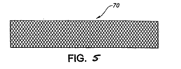
糸の縒り合わせも又、例えば、図6から8に示されているように使用されて、図5に描かれているように、中空管状の縒り合わせ布地の一部70を形成する。図5に描かれているように、糸の縒り合わせは、少なくとも二つの糸のシステムの交錯を含んでいて、それらの糸の道筋は布地の送達方向に対して斜めであって、平坦なまたは管状の構造を形成する。有用な縒り合わせには、図6に示されるように1/1の交差の繰り返しを持つダイアモンド縒り、図7に示されるように2/2の交差の繰り返しを持つ通常の縒り、或いは図8に示されているように3/3の交差の繰り返しを持つヘラクレス縒りが含まれるが、これらに限定されるものではない。その上、三軸性の縒り合わせも又使用されることがある。三軸性の縒り合わせは、図示されてはいないが、典型的に、布地部分の縦方向或いは軸方向に走る少なくとも一本の縒り糸を持ち、糸の動きを制限する。軸或いは縦方向の縒り糸は、他の縒り糸とは交錯したり、または巻き合ったりしないが、縒り合わせ構造内で異なったセットの縒り糸の間にトラップされる。加えて、相互に組み合った三次元の縒り合わせ構造、或いは多重層の縒り合わせ構造も又有用である。多重層の縒り合わせ構造は、その構造が複数の異なった別個の層を持つ縒り合わせによって形成された構造として定義されている。これらの層は、互いに組み合っている縒り糸または粘着性の薄層、縫い合わせ等によって結合されてもよい。
Yarn twisting is also used, for example, as shown in FIGS. 6-8 to form a
一般に、縒り合わせ構造は、縒り合わせ構造の縦軸に対して約54.5°から約90°の縒り合わせ角度、望ましくは約54.5°から約75°の角度を持って形成される。縒り合わせの縒り糸は、約54.5°の縒り合わせ角度で平衡に達しようとする傾向があり、この角度は圧力下にある管状の血管に対する中立の角度である。このようにして、縒り合わせ角度が中立の角度より大きな場合、例えば、血流のために圧力が内部から働く場合、縒り糸は切れて縒り合わせ角度を低下して、それによって縒り合わせ構造を延長または伸張して中立角度に到達しようとする傾向がある。 Generally, the twisting structure is formed with a twisting angle of about 54.5 ° to about 90 °, preferably about 54.5 ° to about 75 °, relative to the longitudinal axis of the twisting structure. The twisted yarn tends to reach equilibrium at a twist angle of about 54.5 °, which is the neutral angle for the tubular vessel under pressure. In this way, if the twisting angle is greater than the neutral angle, for example, if the pressure works from the inside due to blood flow, the twisting thread will break and reduce the twisting angle, thereby extending the twisting structure Or they tend to stretch and try to reach a neutral angle.
加えて、図9及び10に示されているように、編まれた(ニットの)布地部品100を使用してもよい。編み方には、一つの縒り糸システムを縦目及び横目と呼ばれるループの縦列(カラム)と横列にそれぞれループをからませて、布地が織機から縦目方向で出てくることが含まれる。ジャージーウエフトニットのような編み(ニットの)布地のパターンの例が図10に図示されているが、これに限定されるものではない。トリコットまたはダブルトリコットのような縦糸編みパターンも又望ましい。
In addition, as shown in FIGS. 9 and 10, a
織り糸の線密度(長さ当りの重量)を表す織り糸のデニールは、移植片の耐久性と柔軟性を考慮して選ばれることが望ましい。本発明で使用される織り糸は、約1から約1000の、より望ましくは約10から約100の、さらにより望ましくは約20から約60のデニールを持ってもよい。 The denier of the yarn representing the linear density (weight per length) of the yarn is preferably selected in consideration of the durability and flexibility of the graft. The yarns used in the present invention may have a denier of from about 1 to about 1000, more desirably from about 10 to about 100, and even more desirably from about 20 to about 60.
布地層の使用は、このような層が提供する柔軟性、耐久性及び強度が増大するために有利である。例えば、PETは編み、織り、縒り合わせ、又は不織技法によって管状の布地に作り上げられて耐久性のある、思い通りになる強化外層30を形成する。本発明の三層系における外層30を形成するためにこのような素材を使用すると、容易に体に組み込まれる強化され、しかも柔軟な移植片10が提供されて有利である。
The use of fabric layers is advantageous because of the increased flexibility, durability and strength that such layers provide. For example, PET is made into a tubular fabric by knitting, weaving, interlacing, or non-woven techniques to form a durable, desired reinforcing
一旦、布地外層30が形成されると、それは心棒上に配置され、熱固定されて一般に円形の横断面を持つチューブになる。熱固定に先立ち、布地は継ぎ目のない管状の移植片に形成され、もし、それがポリエステルのような熱可塑性素材から構成されているならば、熱固定される。熱固定は布地層を、190°Fから400°Fのような適度の温度にすることによって達成してもよい。
Once the
内層40は、生体適合性のポリマー素材、好ましくは発泡ポリテトラフルオロエチレン(ePTFE)から作り上げられる。発泡PTFEは、例えば、Goreに対する米国特許第3,953,566号に教示のCD123微粉末PTFEレジン(ICI Americas)から当分野では既知の何らかの方法を用いて構成されてもよく、その開示は、本明細書に参照して組み込まれている。
特に望ましい形態においては、内層40は、発泡ポリテトラフルオロエチレン(ePTFE)から作られたチューブに形成される。ペースト押出しによってePTFEチューブを作る方法及び押出し物の発泡法は、当分野では周知のことである。発泡PTFEは、特徴的な節及び節を互いに連結するフィブリル(微細繊維)から構成されている。節とフィブリル(微細繊維)間の間隙は、上記ePTFEの母材全体に渡って存在する小孔を形成している。発泡PTFEの血管移植片は、大部分、その生体適合性及び取扱い上の特性のために少なからぬ支持を受けている。
In a particularly desirable form, the
本発明のAV(動静脈)移植片の中間層50は、望ましくは、生体適合性のゴム性ポリマー、又は他の生体適合性の非ゴム性素材、発泡ポリマー、及び止血に貢献する他の素材から作られる。加えて、何らかの薬物又は生体治療用試薬をこの層に被覆或いは組み込んでもよい。適切な薬物或いは生体治療用試薬の例には、これらに限定されるわけではないが、止血剤、抗生剤、抗がん剤、細胞周期調節剤、それらの同族体、誘導体、断片、薬剤塩及びそれらの組合せが含まれる。血栓形成阻害剤を上記内層40に付加して移植片の開通性を増大してもよい。有用な血栓形成阻害剤には、例えば、ヘパリン、ヘパラン硫酸、ヒルジン、コンドロイチン硫酸、デルマタン硫酸、ケラチン硫酸、ウロキナーゼ及びストレプトキナーゼを含む血栓溶解剤、それらの同族体、類似体、断片、誘導体及びそれらの製剤塩が含まれてもよい。
The AV (arteriovenous) graft
有用な抗生物質には、例えば、ペニシリン、セファロスポリン、バンコマイシン、アミノグリコシド、キノロン、ポリミクシン、エリスロマイシン、テトラサイクリン、クロラムフェニコール、クリンダマイシン、リンコマイシン、スルフォンアミド、それらの同族体、類似体、断片、誘導体、薬剤塩、及びそれらの組合せが含まれてもよい。 Useful antibiotics include, for example, penicillin, cephalosporin, vancomycin, aminoglycoside, quinolone, polymycin, erythromycin, tetracycline, chloramphenicol, clindamycin, lincomycin, sulfonamide, their homologues, analogs, Fragments, derivatives, pharmaceutical salts, and combinations thereof may be included.
有用な抗がん剤には、例えば、パクリタクセル、ドセタクセル、メクロレサミン、クロラムブシル、シクロフォスファミド、メルファラン及びイフォスファミドを含むアルキル化剤、メトトレキセート、6−メルカプトプリン、5−フルオロウラシル及びシタラビンを含む抗代謝剤、ビンブラスチン、ビンクリスチン及びエトポシドを含む植物アルカロイド、ドクソムビシン、ダウノマイシン、ブレオマイシン、及びマイトマイシンを含む抗生物質、カルムスチン及びロムスチンを含むニトロソ尿素、シスプラチンを含む無機イオン、インターフェロンを含む生物応答修飾剤、アスパラギナーゼを含む酵素、及びタモキシフェン及びフルタミドを含むホルモン、それらの同族体、類似体、断片、誘導体、製剤塩、及びそれらの組合せが含まれてもよい。 Useful anticancer agents include, for example, alkylating agents including paclitaxel, docetaxel, mechloresamine, chlorambucil, cyclophosphamide, melphalan and ifosfamide, antimetabolites including methotrexate, 6-mercaptopurine, 5-fluorouracil and cytarabine , Plant alkaloids including vinblastine, vincristine and etoposide, antibiotics including doxumubicin, daunomycin, bleomycin and mitomycin, nitrosoureas including carmustine and lomustine, inorganic ions including cisplatin, biological response modifiers including interferon, including asparaginase Enzymes and hormones including tamoxifen and flutamide, their homologues, analogs, fragments, derivatives, pharmaceutical salts, and combinations thereof It may be.
有用な抗ウイルス剤には、例えば、アマンタディン、リマンタディン、リバビリン、イドクサーリディン、ビダラビン、トリフルリディン、アシクロバー、ガンシクロバー、ジドブディン、フォスカーネット、インターフェロン、それらの同族体、類似体、断片、誘導体、製剤塩、及びそれらの組合せが含まれてもよい。他の有用な抗微生物剤には、金属銀、酸化銀及び燐酸銀のような銀含有物質が含まれてもよい。 Useful antiviral agents include, for example, amantadine, rimantadine, ribavirin, idoxerlidin, vidarabine, trifluridin, acyclobar, ganciclobar, zidobudin, foscarnet, interferon, their homologues, analogs, fragments, derivatives , Pharmaceutical salts, and combinations thereof. Other useful antimicrobial agents may include silver-containing materials such as metallic silver, silver oxide and silver phosphate.
本明細書においては、ゴム性ポリマーは、室温において低応力で少なくともその元の長さの約2倍に伸びることが出来、またその応力の解除に際し、力でもって、そのほぼ元の長さに戻るポリマーとして定義されている。中間層50用としてゴム性ポリマーを選ぶ場合、折れ曲りの低い直径が望ましいが、これはゴム性中間層の厚さと弾性率に対してバランスを取るべきであり、その目的は、許容出来る取扱いの特徴を維持しながら、アクセス部位を通して重大な漏血を防止するに必要な最小限の厚さを選択することにある。中間層50に適切な生体適合性ゴム性ポリマーには、コポリマー(共重合体)には限定されないが、ブロックポリマー、シリコンエラストマー、ポリウレタンエラストマー、ポリウレタン‐カーボネート或いはそれらの組合せを含んでもよく、層の好ましい厚さは約0.01mmから10mm、より望ましくは約1mmから約3mmである。シリコンが中間層として使用される場合は、望ましい厚さは約0.5mmから0.75mmの範囲である。
もう一つの態様において、生体適合性ポリマー層50は生分解性である。中間層50に有用な望ましい生分解性素材にはトリメチレンカーボネート、ポリエチレングリコール、ポリプロピレングリコール、ポリラクチド/ポリグリコリドポリマー、コラーゲン及びアルギネートが含まれるが、これらに限定はされない。
As used herein, a rubbery polymer can stretch at least about twice its original length with low stress at room temperature, and when released from its stress, it can be brought to its original length with force. Defined as returning polymer. When choosing a rubbery polymer for the
In another embodiment, the
一旦、三層が作り上げられると、複合AV移植片10は当分野において既知の何れかの望ましい方法によって形成され得る。例えば、中間層50から形成されたチューブが内層40から形成されたチューブ上に同心的に配置されることが出来、又外層の布地層30が続いて同心的に中間層の上に配置されて移植片10を形成することが出来る。別法として、内層40を心棒上に配置して、その心棒を型枠内に懸垂することが出来る。シリコンラバーの中間層50は、例えば、液状のシリコンラバーを上記型枠内にポンプで汲み入れ、上記液状のシリコンラバーを硬化して固体のラバーチューブを形成し、このようにして形成されている中間層50を内層40の周りに挿入することが出来る。外層30は次いで内層40の周りに配置されることになる。
Once the three layers are created, the
内層40は約4mmから8mmの内径を持つことが出来、5mmから7mmが好ましい内径であり、又約0.01mmから約2.0mmの厚さを持つことが出来、最も望ましくは約0.25mmから約0.75mmである。中間層50は、約0.01mmから約2mm、好ましくは約0.1mmから約1mmの厚さを持つことが出来る。外層チューブは0.5から3mm、最も好ましくは約1から2mmの壁厚を持つことが出来る。内層及び外層チューブの壁厚は同じであっても異なっていてもよい。
内層40から形成される内側チューブの長さは移植片の特定の適用及びチューブが埋め込まれる患者内の部位に左右される。その結果、内部チューブは長さが約100mmから500mmの間で変動することが出来、約250−450mmが、ループ状の前腕移植片に対する最も好ましい長さの範囲である。外側チューブの長さは内側チューブの長さに等しいか又は小さく、10mmから500mmまで長さが変動することが出来、約250−450mmが前腕移植片に対する好ましい長さである。中間層50は二つの管状層の間に配置され、両層以上に伸展することはない。
The length of the inner tube formed from the
別法として、内層40から形成される内側チューブの長さは、外層30から形成される外側チューブの長さに等しいか或いは小さく、長さが10mmから500mmまで変動することが出来、約250−450mmが前腕移植片に対する好ましい長さである。外層及び/或いは中間層が、移植片10の両端まで全面的に伸展することを防止することによって、医療関係者は移植片10の末端に吻合を行うことが出来、同移植片は従来のePTFE移植片と同じ触感特性を発揮することになる。
Alternatively, the length of the inner tube formed from the
[実施例1] 編みカバーを持つePTFE移植片の増大された縫合線維持強度
4種類のePTFE移植片が編みカバーを持つePTFE移植片と比較され、編みカバーが結果として縫合線の維持強度の増大となるか否かが決定された。縫合線の維持力とは、試料の人工器官から縫合線を引き離すのに必要な力、或いは人工器官の壁の不作動を引き起こすに必要な力を意味する。
Example 1 Increased Suture Line Maintenance Strength of an ePTFE Graft with a Knitted Cover Four types of ePTFE grafts are compared to an ePTFE graft with a knitted cover, and the knitted cover results in increased suture maintenance strength. It was decided whether or not. Suture retention force means the force required to pull the suture away from the sample prosthesis or the force required to cause the prosthesis wall to become inoperable.
Exxcel TM 軟移植片(6mm SW, Boston Scientific, Boston, MA),the Exxcel TM 移植片(6mm SW Boston Scientific, Boston,MA),インプラ(6mm SW, Droitwich, UK)及びGore 移植片(6mm SW,Gore Enterprises Holdings,Inc,Newark,DE)が編みカバーを有する移植片との比較に使用された。縫合線維持強度が、移植片のそれぞれについて下記のように縦操作及び斜め操作を用いて検討された。 Exxcel ™ soft graft (6mm SW, Boston Scientific, Boston, MA), the Exxcel ™ graft (6mm SW Boston Scientific, Boston, MA), implant (6mm SW, mmWrG) Gore Enterprises Holdings, Inc, Newark, DE) was used for comparison with grafts with knitted covers. Suture line maintenance strength was examined for each of the grafts using longitudinal and diagonal operations as described below.
縦操作
各人工器官を長軸に直角に切れ目を入れた(cut normal to the long axis)。縫合線を人工器官の一つの壁を通して引張った人工器官の末端から2mmのところに入れて半ループを形成した。縫合線を一分間に150mmの速度で引っ張った。人工器官を通して縫合線を引っ張るのに要する力或いは人工器官の壁の不全(崩壊)を引き起こすのに要する力が記録された(グラムで測定)。すべてのテストは医療器具推進協会の必要条件に従って行われた。
Longitudinal operation Each prosthesis was cut perpendicular to the long axis (cut normal to the long axis). A suture was placed 2 mm from the end of the prosthesis pulled through one wall of the prosthesis to form a half loop. The suture was pulled at a speed of 150 mm per minute. The force required to pull the suture through the prosthesis or the force required to cause failure (collapse) of the prosthetic wall was recorded (measured in grams). All tests were conducted according to the requirements of the Medical Device Promotion Association.
斜め操作
人工器官を長軸に対して45度で切れ目を入れた。縫合線を切断部の基部(ヒール、かかと)に入れた。人工器官を通して縫合線を引っ張る力或いは人工器官の壁の不全(崩壊)を引き起こすに要する力を各試料人工器官に対してグラムで記録した。
Diagonal operation The prosthesis was cut at 45 degrees to the long axis. A suture was placed in the base of the cut (heel, heel). The force pulling the suture through the prosthesis or the force required to cause failure (collapse) of the prosthetic wall was recorded in grams for each sample prosthesis.
両操作の結果が表1に記載されている。
これらの結果は、試料5において使用されている編みカバーのような、本発明に従う布地のカバーを有する移植片が、斜め又は縦操作を用いる場合、人工器官の縫合線維持強度を有意に改善することを確認するものである。 These results show that an implant having a fabric cover according to the present invention, such as the knitted cover used in Sample 5, significantly improves the suture maintenance strength of the prosthesis when using diagonal or longitudinal manipulation. It is to confirm that.
[実施例2] 反復穿刺によって測定された編み外カバーを有するePTFE移植片の耐久性
加えて、上記の移植片5個の耐久性について反復穿刺テストを用いて検討した。このテストの意図は、透析使用を模擬して反復穿刺した後、人工器官の強度を決定することにある。試料は反復穿刺され、次いで、加圧破裂強度を検査された。
[Example 2] Durability of an ePTFE graft having an outer knitted cover measured by repeated puncture In addition, the durability of the above-mentioned five grafts was examined using a repeated puncture test. The intent of this test is to determine the strength of the prosthesis after repeated punctures simulating dialysis use. Samples were repeatedly punctured and then examined for pressure burst strength.
16ゲージの透析針を用い、試料人工器官を、人工器官の外表面面積の1平方センチメートル当り8、16及び24回穿刺した。これらの数値は、ほぼ6,12及び18ヶ月の臨床使用に相当するものである。これは、30cm長の人工器官の外表面面積の3分の1に、週に6回の穿刺を想定したものである。 Using a 16 gauge dialysis needle, the sample prosthesis was punctured 8, 16, and 24 times per square centimeter of the outer surface area of the prosthesis. These numbers correspond to approximately 6, 12 and 18 months of clinical use. This assumes six punctures per week in one third of the outer surface area of a 30 cm long prosthesis.
反復穿刺の後、試料人工器官は、その破裂が起こるまで、人工器官を直接液体で満たすか、或いは、その内部にバルーンを設置し、バルーンを液体で正確に測った圧力変化速度で満たすことによって膨張させた。このテストの結果は表2に示されている。
表2からの結果は、本発明に従い外側に編みカバーを有する接触片が、反復穿刺操作によって測定される場合、人工器官の耐久性を有意に増大することを明らかに示している。 The results from Table 2 clearly show that contact pieces having a knitted cover on the outside according to the present invention significantly increase the durability of the prosthesis when measured by repeated puncture operations.
本明細書に好ましい態様を述べてきたが、当然のことながら、本発明の企図する範囲から逸脱することなくそれらの態様に種々の改変がなされてもよい。従って、本明細書に記載の好ましい態様は、本文書に付帯の特許請求の範囲に述べられている当発明の真の範囲を限定するよりもむしろ説明のためであることを意図するものである。 While preferred embodiments have been described herein, it will be appreciated that various modifications may be made to these embodiments without departing from the intended scope of the invention. Accordingly, the preferred embodiments described herein are intended to be illustrative rather than limiting the true scope of the invention as set forth in the claims appended hereto. .
Claims (20)
Applications Claiming Priority (2)
| Application Number | Priority Date | Filing Date | Title |
|---|---|---|---|
| US10/422,118 US7452374B2 (en) | 2003-04-24 | 2003-04-24 | AV grafts with rapid post-operative self-sealing capabilities |
| PCT/US2004/012404 WO2004096307A1 (en) | 2003-04-24 | 2004-04-22 | Av grafts with rapid post-operative self-sealing capabilities |
Publications (1)
| Publication Number | Publication Date |
|---|---|
| JP2006524117A true JP2006524117A (en) | 2006-10-26 |
Family
ID=33298810
Family Applications (1)
| Application Number | Title | Priority Date | Filing Date |
|---|---|---|---|
| JP2006513212A Pending JP2006524117A (en) | 2003-04-24 | 2004-04-22 | Arteriovenous grafts with the ability to seal themselves quickly after surgery |
Country Status (5)
| Country | Link |
|---|---|
| US (1) | US7452374B2 (en) |
| EP (1) | EP1631332A1 (en) |
| JP (1) | JP2006524117A (en) |
| CA (1) | CA2525489A1 (en) |
| WO (1) | WO2004096307A1 (en) |
Cited By (1)
| Publication number | Priority date | Publication date | Assignee | Title |
|---|---|---|---|---|
| JP2018519893A (en) * | 2015-06-05 | 2018-07-26 | ダブリュ.エル.ゴア アンド アソシエイツ,インコーポレイティドW.L. Gore & Associates, Incorporated | Tapered hypobleedable implantable prosthesis |
Families Citing this family (66)
| Publication number | Priority date | Publication date | Assignee | Title |
|---|---|---|---|---|
| US6102884A (en) | 1997-02-07 | 2000-08-15 | Squitieri; Rafael | Squitieri hemodialysis and vascular access systems |
| US7998188B2 (en) | 2003-04-28 | 2011-08-16 | Kips Bay Medical, Inc. | Compliant blood vessel graft |
| US20050131520A1 (en) * | 2003-04-28 | 2005-06-16 | Zilla Peter P. | Compliant blood vessel graft |
| US8057537B2 (en) * | 2003-04-28 | 2011-11-15 | Kips Bay Medical, Inc. | Compliant venous graft |
| US7762977B2 (en) | 2003-10-08 | 2010-07-27 | Hemosphere, Inc. | Device and method for vascular access |
| US7794490B2 (en) * | 2004-06-22 | 2010-09-14 | Boston Scientific Scimed, Inc. | Implantable medical devices with antimicrobial and biodegradable matrices |
| WO2006026725A2 (en) | 2004-08-31 | 2006-03-09 | C.R. Bard, Inc. | Self-sealing ptfe graft with kink resistance |
| US8029563B2 (en) | 2004-11-29 | 2011-10-04 | Gore Enterprise Holdings, Inc. | Implantable devices with reduced needle puncture site leakage |
| EP1838242A2 (en) * | 2005-01-21 | 2007-10-03 | Gen 4, LLC | Modular stent graft employing bifurcated graft and leg locking stent elements |
| WO2006080008A2 (en) * | 2005-01-25 | 2006-08-03 | Nicast Ltd. | Artificial vascular prosthesis |
| JP4527156B2 (en) * | 2005-02-14 | 2010-08-18 | ヴァスキュテック リミテッド | Artificial blood vessel |
| US7833263B2 (en) * | 2005-04-01 | 2010-11-16 | Boston Scientific Scimed, Inc. | Hybrid vascular graft reinforcement |
| GB0511431D0 (en) * | 2005-06-04 | 2005-07-13 | Vascutek Ltd | Graft |
| US20110076315A1 (en) * | 2005-06-08 | 2011-03-31 | C.R Bard, Inc. | Grafts and Stents Having Inorganic Bio-Compatible Calcium Salt |
| US8066758B2 (en) | 2005-06-17 | 2011-11-29 | C. R. Bard, Inc. | Vascular graft with kink resistance after clamping |
| EP1945138A4 (en) | 2005-11-09 | 2010-02-10 | Bard Inc C R | Grafts and stent grafts having a radiopaque marker |
| US8163002B2 (en) * | 2005-11-14 | 2012-04-24 | Vascular Devices Llc | Self-sealing vascular graft |
| US20070167901A1 (en) * | 2005-11-17 | 2007-07-19 | Herrig Judson A | Self-sealing residual compressive stress graft for dialysis |
| US8048255B2 (en) * | 2006-01-27 | 2011-11-01 | Medtronic, Inc. | Heatset annuloplasty suture guide |
| US20070203564A1 (en) * | 2006-02-28 | 2007-08-30 | Boston Scientific Scimed, Inc. | Biodegradable implants having accelerated biodegradation properties in vivo |
| US9198749B2 (en) | 2006-10-12 | 2015-12-01 | C. R. Bard, Inc. | Vascular grafts with multiple channels and methods for making |
| JP5973121B2 (en) | 2007-01-30 | 2016-08-23 | ユニバーシティ オブ ピッツバーグ オブ ザ コモンウェルス システム オブ ハイヤー エデュケイション | Biodegradable wrapping and use thereof |
| US8066755B2 (en) | 2007-09-26 | 2011-11-29 | Trivascular, Inc. | System and method of pivoted stent deployment |
| US8663309B2 (en) | 2007-09-26 | 2014-03-04 | Trivascular, Inc. | Asymmetric stent apparatus and method |
| US8226701B2 (en) | 2007-09-26 | 2012-07-24 | Trivascular, Inc. | Stent and delivery system for deployment thereof |
| CA2701096A1 (en) | 2007-10-04 | 2009-04-09 | Trivascular, Inc. | Modular vascular graft for low profile percutaneous delivery |
| US8083789B2 (en) | 2007-11-16 | 2011-12-27 | Trivascular, Inc. | Securement assembly and method for expandable endovascular device |
| US8328861B2 (en) | 2007-11-16 | 2012-12-11 | Trivascular, Inc. | Delivery system and method for bifurcated graft |
| US20110295181A1 (en) | 2008-03-05 | 2011-12-01 | Hemosphere, Inc. | Implantable and removable customizable body conduit |
| US8079973B2 (en) * | 2008-03-05 | 2011-12-20 | Hemosphere Inc. | Vascular access system |
| US9468515B2 (en) * | 2009-07-01 | 2016-10-18 | Correx, Inc. | Method and apparatus for effecting a percutaneous aortic valve bypass |
| US9622849B2 (en) | 2009-10-28 | 2017-04-18 | University of Pittsburgh—of the Commonwealth System of Higher Education | Bioerodible wraps and uses therefor |
| AU2010339931B2 (en) | 2009-12-16 | 2016-01-14 | Neograft Technologies, Inc. | Graft devices and methods of use |
| CA2785989A1 (en) | 2009-12-31 | 2011-07-07 | Neograft Technologies, Inc. | Graft devices and methods of fabrication |
| WO2011112755A2 (en) | 2010-03-09 | 2011-09-15 | Solinas Medical Inc. | Self-closing devices and methods for making and using them |
| US8696738B2 (en) | 2010-05-20 | 2014-04-15 | Maquet Cardiovascular Llc | Composite prosthesis with external polymeric support structure and methods of manufacturing the same |
| EP2595695B1 (en) | 2010-07-19 | 2019-02-06 | Neograft Technologies, Inc. | Graft devices and methods of use |
| FR2971971B1 (en) * | 2011-02-24 | 2014-07-11 | Zodiac Automotive Division | DRESSING AND DRESSING MATERIAL BASED ON HYDROCOLLOID FIBERS AND SILICONE GEL |
| EP2686033B1 (en) | 2011-03-16 | 2015-05-06 | Duke University | Arteriovenous graft for hemodialysis with puncture-resistant posterior and side walls |
| WO2013016349A2 (en) | 2011-07-25 | 2013-01-31 | Neograft Technologies, Inc. | Vessel treatment methods and devices for use in a graft device |
| WO2013036643A2 (en) | 2011-09-06 | 2013-03-14 | Hemosphere, Inc. | Vascular access system with connector |
| US9155610B2 (en) | 2011-12-13 | 2015-10-13 | Neograft Technologies, Inc. | System and atraumatic mandrel for creating graft devices |
| US8992595B2 (en) | 2012-04-04 | 2015-03-31 | Trivascular, Inc. | Durable stent graft with tapered struts and stable delivery methods and devices |
| US9498363B2 (en) | 2012-04-06 | 2016-11-22 | Trivascular, Inc. | Delivery catheter for endovascular device |
| US9622892B2 (en) | 2012-04-26 | 2017-04-18 | Cook Medical Technologies Llc | Longitudinally reinforced sheath |
| EP2983625B1 (en) * | 2013-04-13 | 2024-02-14 | Solinas Medical, Inc. | Self-closing devices and apparatus and methods for making and delivering them |
| US9814560B2 (en) | 2013-12-05 | 2017-11-14 | W. L. Gore & Associates, Inc. | Tapered implantable device and methods for making such devices |
| US10682453B2 (en) | 2013-12-20 | 2020-06-16 | Merit Medical Systems, Inc. | Vascular access system with reinforcement member |
| EP3075893B1 (en) * | 2015-04-02 | 2018-09-12 | Karl Mayer Textilmaschinenfabrik GmbH | Knitwear and method for manufacturing knitwear |
| JP7222881B2 (en) | 2016-04-25 | 2023-02-15 | ソリナス メディカル インコーポレイテッド | Self-sealing tubular grafts, patches, methods of making and using same |
| WO2018089625A2 (en) | 2016-11-10 | 2018-05-17 | Merit Medical Systems, Inc. | Anchor device for vascular anastomosis |
| WO2018132573A1 (en) | 2017-01-12 | 2018-07-19 | Merit Medical Systems, Inc. | Methods and systems for selection and use of connectors between conduits |
| US11590010B2 (en) | 2017-01-25 | 2023-02-28 | Merit Medical Systems, Inc. | Methods and systems for facilitating laminar flow between conduits |
| ES2991874T3 (en) | 2017-03-06 | 2024-12-05 | Merit Medical Systems Inc | Systems and methods for removing clots from vascular access sets |
| EP3600150B1 (en) | 2017-03-24 | 2023-05-17 | Merit Medical Systems, Inc. | Subcutaneous vascular assemblies for improving blood flow |
| IL269709B2 (en) | 2017-03-31 | 2024-03-01 | Innavasc Medical Inc | Device and method for inserting a graft tube in a vascular approach |
| WO2019014444A2 (en) | 2017-07-14 | 2019-01-17 | Merit Medical Systems, Inc. | Releasable conduit connectors |
| EP3655086A4 (en) | 2017-07-20 | 2021-04-07 | Merit Medical Systems, Inc. | METHODS AND SYSTEMS FOR COUPLING PIPES |
| GB201717885D0 (en) * | 2017-10-31 | 2017-12-13 | Hothouse Medical Ltd | Prothesis and method of manufacture |
| WO2019089569A1 (en) | 2017-10-31 | 2019-05-09 | Merit Medical Systems, Inc. | Subcutaneous vascular assemblies for improving blood flow and related devices and methods |
| US11027046B2 (en) | 2017-10-31 | 2021-06-08 | Hothouse Medical Limited | Textile products having selectively applied sealant or coating and method of manufacture |
| WO2019195353A1 (en) * | 2018-04-04 | 2019-10-10 | Sainess Marius | Low profile self-sealing access port |
| CN108517614A (en) * | 2018-04-13 | 2018-09-11 | 相里海霞 | A kind of seaweed fiber fabric |
| US11925781B2 (en) | 2018-10-30 | 2024-03-12 | InnAVasc Medical, Inc. | Apparatus and method for cannulation of vascular access vessel |
| AU2024238188A1 (en) * | 2023-03-22 | 2025-06-12 | Ascense Medical Gmbh | A composite compliant vascular graft |
| EP4494600B1 (en) * | 2023-07-19 | 2026-01-21 | Hector Daniel Barone | Vascular access prosthesis for hemodialysis |
Citations (5)
| Publication number | Priority date | Publication date | Assignee | Title |
|---|---|---|---|---|
| US4619641A (en) * | 1984-11-13 | 1986-10-28 | Mount Sinai School Of Medicine Of The City University Of New York | Coaxial double lumen anteriovenous grafts |
| EP0492481A1 (en) * | 1990-12-27 | 1992-07-01 | Corvita Corporation | Mesh composite graft |
| JP2002522155A (en) * | 1998-08-14 | 2002-07-23 | ボストン・サイエンティフィク・サイムド・インコーポレーテッド | Stent / graft / membrane and manufacturing method thereof |
| JP2003511196A (en) * | 1999-10-15 | 2003-03-25 | エドワーズ ライフサイエンシーズ コーポレイション | Stackable self-sealing vascular access graft |
| JP2004538090A (en) * | 2001-07-23 | 2004-12-24 | ノボバスキュラー インコーポレーテッド | Nitrogen oxide releasing ePTFE coated medical device sandwich |
Family Cites Families (57)
| Publication number | Priority date | Publication date | Assignee | Title |
|---|---|---|---|---|
| GB571657A (en) | 1942-09-01 | 1945-09-04 | Courtaulds Ltd | Improvements in and relating to the manufacture of alginate threads |
| GB567641A (en) | 1942-09-01 | 1945-02-26 | Courtaulds Ltd | Improvements in and relating to the manufacture of alginate threads |
| GB568177A (en) | 1943-02-19 | 1945-03-22 | Courtaulds Ltd | Improvements in and relating to the manufacture of threads, filaments, films and thelike from alginates |
| GB624987A (en) | 1947-07-22 | 1949-06-20 | Courtaulds Ltd | Improvements in and relating to the manufacture of alginate threads |
| US3479670A (en) | 1966-10-19 | 1969-11-25 | Ethicon Inc | Tubular prosthetic implant having helical thermoplastic wrapping therearound |
| CA962021A (en) | 1970-05-21 | 1975-02-04 | Robert W. Gore | Porous products and process therefor |
| GB1527592A (en) | 1974-08-05 | 1978-10-04 | Ici Ltd | Wound dressing |
| US4047252A (en) | 1976-01-29 | 1977-09-13 | Meadox Medicals, Inc. | Double-velour synthetic vascular graft |
| JPS6037733B2 (en) | 1978-10-12 | 1985-08-28 | 住友電気工業株式会社 | Tubular organ prosthesis material and its manufacturing method |
| US4550447A (en) | 1983-08-03 | 1985-11-05 | Shiley Incorporated | Vascular graft prosthesis |
| US4718907A (en) | 1985-06-20 | 1988-01-12 | Atrium Medical Corporation | Vascular prosthesis having fluorinated coating with varying F/C ratio |
| US4652263A (en) | 1985-06-20 | 1987-03-24 | Atrium Medical Corporation | Elasticization of microporous woven tubes |
| US5061276A (en) | 1987-04-28 | 1991-10-29 | Baxter International Inc. | Multi-layered poly(tetrafluoroethylene)/elastomer materials useful for in vivo implantation |
| US4892539A (en) | 1988-02-08 | 1990-01-09 | D-R Medical Systems, Inc. | Vascular graft |
| US5178630A (en) | 1990-08-28 | 1993-01-12 | Meadox Medicals, Inc. | Ravel-resistant, self-supporting woven graft |
| SE9102448D0 (en) | 1990-08-28 | 1991-08-26 | Meadox Medicals Inc | RAVEL RESISTANT, SELF-SUPPORTING WOVEN GRAFT |
| US5163951A (en) | 1990-12-27 | 1992-11-17 | Corvita Corporation | Mesh composite graft |
| US5192310A (en) | 1991-09-16 | 1993-03-09 | Atrium Medical Corporation | Self-sealing implantable vascular graft |
| US5411550A (en) | 1991-09-16 | 1995-05-02 | Atrium Medical Corporation | Implantable prosthetic device for the delivery of a bioactive material |
| US5366504A (en) | 1992-05-20 | 1994-11-22 | Boston Scientific Corporation | Tubular medical prosthesis |
| US5866217A (en) | 1991-11-04 | 1999-02-02 | Possis Medical, Inc. | Silicone composite vascular graft |
| AU676831B2 (en) | 1992-03-13 | 1997-03-27 | Atrium Medical Corporation | Controlled porosity expanded polytetrafluoroethylene products and fabrication |
| US5456711A (en) | 1992-05-15 | 1995-10-10 | Intervascular Inc. | Warp knitted carotid patch having finished selvedged edges |
| US5562725A (en) | 1992-09-14 | 1996-10-08 | Meadox Medicals Inc. | Radially self-expanding implantable intraluminal device |
| US5628782A (en) | 1992-12-11 | 1997-05-13 | W. L. Gore & Associates, Inc. | Method of making a prosthetic vascular graft |
| US5716395A (en) * | 1992-12-11 | 1998-02-10 | W.L. Gore & Associates, Inc. | Prosthetic vascular graft |
| GB9306812D0 (en) | 1993-04-01 | 1993-05-26 | Vascutek Ltd | Textile prostheses |
| US5913894A (en) | 1994-12-05 | 1999-06-22 | Meadox Medicals, Inc. | Solid woven tubular prosthesis |
| US5370682A (en) | 1993-04-26 | 1994-12-06 | Meadox Medicals, Inc. | Solid woven tubular prosthesis |
| AU8012394A (en) | 1993-10-01 | 1995-05-01 | Emory University | Self-expanding intraluminal composite prosthesis |
| US5723004A (en) | 1993-10-21 | 1998-03-03 | Corvita Corporation | Expandable supportive endoluminal grafts |
| US5527353A (en) | 1993-12-02 | 1996-06-18 | Meadox Medicals, Inc. | Implantable tubular prosthesis |
| US5741332A (en) | 1995-01-23 | 1998-04-21 | Meadox Medicals, Inc. | Three-dimensional braided soft tissue prosthesis |
| US5591226A (en) | 1995-01-23 | 1997-01-07 | Schneider (Usa) Inc. | Percutaneous stent-graft and method for delivery thereof |
| US5904967A (en) | 1995-04-27 | 1999-05-18 | Terumo Kabushiki Kaisha | Puncture resistant medical material |
| EP0830110B2 (en) | 1995-06-07 | 2010-08-04 | Edwards Lifesciences Corporation | Externally supported tape reinforced vascular graft |
| US5769882A (en) * | 1995-09-08 | 1998-06-23 | Medtronic, Inc. | Methods and apparatus for conformably sealing prostheses within body lumens |
| US6428571B1 (en) * | 1996-01-22 | 2002-08-06 | Scimed Life Systems, Inc. | Self-sealing PTFE vascular graft and manufacturing methods |
| US5800512A (en) | 1996-01-22 | 1998-09-01 | Meadox Medicals, Inc. | PTFE vascular graft |
| US5728103A (en) | 1996-08-23 | 1998-03-17 | Applied Medical Technology, Inc. | Implantable subcutaneous access device and method of using same |
| US5879320A (en) | 1996-12-23 | 1999-03-09 | Cazenave; Craig Richard | Implantable vascular device |
| US5957974A (en) | 1997-01-23 | 1999-09-28 | Schneider (Usa) Inc | Stent graft with braided polymeric sleeve |
| US6102884A (en) | 1997-02-07 | 2000-08-15 | Squitieri; Rafael | Squitieri hemodialysis and vascular access systems |
| DE19720115C2 (en) | 1997-05-14 | 1999-05-20 | Jomed Implantate Gmbh | Stent graft |
| US5931865A (en) | 1997-11-24 | 1999-08-03 | Gore Enterprise Holdings, Inc. | Multiple-layered leak resistant tube |
| WO1999026559A1 (en) | 1997-11-25 | 1999-06-03 | Triad Vascular Systems, Inc. | Layered endovascular graft |
| US6056970A (en) * | 1998-05-07 | 2000-05-02 | Genzyme Corporation | Compositions comprising hemostatic compounds and bioabsorbable polymers |
| US6261257B1 (en) | 1998-05-26 | 2001-07-17 | Renan P. Uflacker | Dialysis graft system with self-sealing access ports |
| US6261255B1 (en) | 1998-11-06 | 2001-07-17 | Ronald Jay Mullis | Apparatus for vascular access for chronic hemodialysis |
| US6440166B1 (en) | 1999-02-16 | 2002-08-27 | Omprakash S. Kolluri | Multilayer and multifunction vascular graft |
| US6333029B1 (en) * | 1999-06-30 | 2001-12-25 | Ethicon, Inc. | Porous tissue scaffoldings for the repair of regeneration of tissue |
| US6361556B1 (en) | 2000-04-27 | 2002-03-26 | Endovascular Tech Inc | System and method for endovascular aneurysm repair in conjuction with vascular stabilization |
| US6547820B1 (en) * | 2000-10-03 | 2003-04-15 | Scimed Life Systems, Inc. | High profile fabric graft for arteriovenous access |
| US20020084178A1 (en) * | 2000-12-19 | 2002-07-04 | Nicast Corporation Ltd. | Method and apparatus for manufacturing polymer fiber shells via electrospinning |
| JP4401165B2 (en) * | 2001-06-11 | 2010-01-20 | ボストン サイエンティフィック リミテッド | Composite ePTFE / fiber prosthesis |
| US7828833B2 (en) * | 2001-06-11 | 2010-11-09 | Boston Scientific Scimed, Inc. | Composite ePTFE/textile prosthesis |
| US6926735B2 (en) * | 2002-12-23 | 2005-08-09 | Scimed Life Systems, Inc. | Multi-lumen vascular grafts having improved self-sealing properties |
-
2003
- 2003-04-24 US US10/422,118 patent/US7452374B2/en not_active Expired - Fee Related
-
2004
- 2004-04-22 CA CA002525489A patent/CA2525489A1/en not_active Abandoned
- 2004-04-22 WO PCT/US2004/012404 patent/WO2004096307A1/en not_active Ceased
- 2004-04-22 EP EP04760324A patent/EP1631332A1/en not_active Withdrawn
- 2004-04-22 JP JP2006513212A patent/JP2006524117A/en active Pending
Patent Citations (5)
| Publication number | Priority date | Publication date | Assignee | Title |
|---|---|---|---|---|
| US4619641A (en) * | 1984-11-13 | 1986-10-28 | Mount Sinai School Of Medicine Of The City University Of New York | Coaxial double lumen anteriovenous grafts |
| EP0492481A1 (en) * | 1990-12-27 | 1992-07-01 | Corvita Corporation | Mesh composite graft |
| JP2002522155A (en) * | 1998-08-14 | 2002-07-23 | ボストン・サイエンティフィク・サイムド・インコーポレーテッド | Stent / graft / membrane and manufacturing method thereof |
| JP2003511196A (en) * | 1999-10-15 | 2003-03-25 | エドワーズ ライフサイエンシーズ コーポレイション | Stackable self-sealing vascular access graft |
| JP2004538090A (en) * | 2001-07-23 | 2004-12-24 | ノボバスキュラー インコーポレーテッド | Nitrogen oxide releasing ePTFE coated medical device sandwich |
Cited By (4)
| Publication number | Priority date | Publication date | Assignee | Title |
|---|---|---|---|---|
| JP2018519893A (en) * | 2015-06-05 | 2018-07-26 | ダブリュ.エル.ゴア アンド アソシエイツ,インコーポレイティドW.L. Gore & Associates, Incorporated | Tapered hypobleedable implantable prosthesis |
| JP2020110612A (en) * | 2015-06-05 | 2020-07-27 | ダブリュ.エル.ゴア アンド アソシエイツ,インコーポレイティドW.L. Gore & Associates, Incorporated | Tapered low hemorrhagic implantable prosthesis |
| JP7021275B2 (en) | 2015-06-05 | 2022-02-16 | ダブリュ.エル.ゴア アンド アソシエイツ,インコーポレイティド | Tapered hypobleeding implantable prosthesis |
| US12521257B2 (en) | 2015-06-05 | 2026-01-13 | W. L. Gore & Associates, Inc. | Low bleed implantable prosthesis with a taper |
Also Published As
| Publication number | Publication date |
|---|---|
| WO2004096307A1 (en) | 2004-11-11 |
| US20040215337A1 (en) | 2004-10-28 |
| US7452374B2 (en) | 2008-11-18 |
| CA2525489A1 (en) | 2004-11-11 |
| EP1631332A1 (en) | 2006-03-08 |
Similar Documents
| Publication | Publication Date | Title |
|---|---|---|
| JP2006524117A (en) | Arteriovenous grafts with the ability to seal themselves quickly after surgery | |
| JP2939337B2 (en) | Three-dimensional braided soft tissue prosthesis | |
| US5700287A (en) | Prosthetic vascular graft with deflectably secured fibers | |
| EP1796587B1 (en) | Composite vascular graft with antimicrobial and biodegradable matrices and an outer fabric layer | |
| TWI766853B (en) | Warp knitted fabrics and medical materials | |
| US5910168A (en) | Prosthetic vascular graft | |
| US5320100A (en) | Implantable prosthetic device having integral patency diagnostic indicia | |
| AU676666B2 (en) | Controlled porosity implantable primary lumen device | |
| JP2006511282A (en) | Multi-lumen vascular graft with improved self-sealing properties | |
| JP2004526472A (en) | High profile cloth graft for arteriovenous access | |
| KR20140132366A (en) | Improved biocompatible surfaces and devices incorporating such surfaces | |
| RU2670970C1 (en) | Vascular prosthesis | |
| JP2020536625A (en) | Flexible hollow cavity composite | |
| US20210059807A1 (en) | Strong, flexible, and thrombus-free woven nanotextile based vascular grafts, and method of production thereof | |
| JP3591868B2 (en) | Artificial prosthesis | |
| JP3766755B2 (en) | In vivo indwelling tube | |
| JPH04250167A (en) | Medical prosthesis material | |
| Mankodi | Application of textile materials in cardiovascular implants | |
| Planck | General Aspects in the use of Medical Textiles for Implantation | |
| EP4497412A1 (en) | Aortic implant with proximal anchoring layer | |
| RU2670671C2 (en) | Vascular prosthesis |
Legal Events
| Date | Code | Title | Description |
|---|---|---|---|
| A521 | Request for written amendment filed |
Free format text: JAPANESE INTERMEDIATE CODE: A821 Effective date: 20060202 |
|
| A711 | Notification of change in applicant |
Free format text: JAPANESE INTERMEDIATE CODE: A711 Effective date: 20060202 |
|
| A521 | Request for written amendment filed |
Free format text: JAPANESE INTERMEDIATE CODE: A523 Effective date: 20060615 |
|
| A521 | Request for written amendment filed |
Free format text: JAPANESE INTERMEDIATE CODE: A821 Effective date: 20060616 |
|
| A621 | Written request for application examination |
Free format text: JAPANESE INTERMEDIATE CODE: A621 Effective date: 20070411 |
|
| A621 | Written request for application examination |
Free format text: JAPANESE INTERMEDIATE CODE: A621 Effective date: 20070411 |
|
| A711 | Notification of change in applicant |
Free format text: JAPANESE INTERMEDIATE CODE: A711 Effective date: 20080326 |
|
| A521 | Request for written amendment filed |
Free format text: JAPANESE INTERMEDIATE CODE: A821 Effective date: 20080326 |
|
| A131 | Notification of reasons for refusal |
Free format text: JAPANESE INTERMEDIATE CODE: A131 Effective date: 20100914 |
|
| A601 | Written request for extension of time |
Free format text: JAPANESE INTERMEDIATE CODE: A601 Effective date: 20101214 |
|
| A602 | Written permission of extension of time |
Free format text: JAPANESE INTERMEDIATE CODE: A602 Effective date: 20101221 |
|
| A601 | Written request for extension of time |
Free format text: JAPANESE INTERMEDIATE CODE: A601 Effective date: 20110113 |
|
| A602 | Written permission of extension of time |
Free format text: JAPANESE INTERMEDIATE CODE: A602 Effective date: 20110120 |
|
| A601 | Written request for extension of time |
Free format text: JAPANESE INTERMEDIATE CODE: A601 Effective date: 20110214 |
|
| A602 | Written permission of extension of time |
Free format text: JAPANESE INTERMEDIATE CODE: A602 Effective date: 20110221 |
|
| A02 | Decision of refusal |
Free format text: JAPANESE INTERMEDIATE CODE: A02 Effective date: 20110705 |