JP2006351346A - Redox flow battery system - Google Patents
Redox flow battery system Download PDFInfo
- Publication number
- JP2006351346A JP2006351346A JP2005175776A JP2005175776A JP2006351346A JP 2006351346 A JP2006351346 A JP 2006351346A JP 2005175776 A JP2005175776 A JP 2005175776A JP 2005175776 A JP2005175776 A JP 2005175776A JP 2006351346 A JP2006351346 A JP 2006351346A
- Authority
- JP
- Japan
- Prior art keywords
- cell
- electrolyte
- main cell
- monitor
- supplied
- Prior art date
- Legal status (The legal status is an assumption and is not a legal conclusion. Google has not performed a legal analysis and makes no representation as to the accuracy of the status listed.)
- Pending
Links
- 239000003792 electrolyte Substances 0.000 claims abstract description 203
- 238000000034 method Methods 0.000 claims abstract description 19
- 239000008151 electrolyte solution Substances 0.000 claims description 62
- 238000006243 chemical reaction Methods 0.000 claims description 52
- 230000005856 abnormality Effects 0.000 claims description 25
- 229910001456 vanadium ion Inorganic materials 0.000 claims description 23
- 239000000243 solution Substances 0.000 claims description 19
- 238000005259 measurement Methods 0.000 claims description 17
- 229940021013 electrolyte solution Drugs 0.000 description 34
- 150000002500 ions Chemical class 0.000 description 30
- 230000007423 decrease Effects 0.000 description 8
- 238000007599 discharging Methods 0.000 description 8
- 229910052720 vanadium Inorganic materials 0.000 description 8
- OKTJSMMVPCPJKN-UHFFFAOYSA-N Carbon Chemical compound [C] OKTJSMMVPCPJKN-UHFFFAOYSA-N 0.000 description 5
- BZHJMEDXRYGGRV-UHFFFAOYSA-N Vinyl chloride Chemical compound ClC=C BZHJMEDXRYGGRV-UHFFFAOYSA-N 0.000 description 5
- 229910052799 carbon Inorganic materials 0.000 description 5
- 239000007788 liquid Substances 0.000 description 5
- LEONUFNNVUYDNQ-UHFFFAOYSA-N vanadium atom Chemical compound [V] LEONUFNNVUYDNQ-UHFFFAOYSA-N 0.000 description 5
- 230000002159 abnormal effect Effects 0.000 description 4
- 238000010586 diagram Methods 0.000 description 4
- 230000008054 signal transmission Effects 0.000 description 4
- 230000003247 decreasing effect Effects 0.000 description 3
- 238000001514 detection method Methods 0.000 description 3
- 238000005868 electrolysis reaction Methods 0.000 description 2
- 239000011810 insulating material Substances 0.000 description 2
- 239000003014 ion exchange membrane Substances 0.000 description 2
- 238000012423 maintenance Methods 0.000 description 2
- 238000011017 operating method Methods 0.000 description 2
- 230000002093 peripheral effect Effects 0.000 description 2
- 229920003023 plastic Polymers 0.000 description 2
- 238000012545 processing Methods 0.000 description 2
- 239000011347 resin Substances 0.000 description 2
- 229920005989 resin Polymers 0.000 description 2
- 230000005540 biological transmission Effects 0.000 description 1
- 239000000470 constituent Substances 0.000 description 1
- 238000010276 construction Methods 0.000 description 1
- 230000006866 deterioration Effects 0.000 description 1
- 239000000463 material Substances 0.000 description 1
- 238000010248 power generation Methods 0.000 description 1
- 238000012360 testing method Methods 0.000 description 1
Images


Classifications
-
- Y—GENERAL TAGGING OF NEW TECHNOLOGICAL DEVELOPMENTS; GENERAL TAGGING OF CROSS-SECTIONAL TECHNOLOGIES SPANNING OVER SEVERAL SECTIONS OF THE IPC; TECHNICAL SUBJECTS COVERED BY FORMER USPC CROSS-REFERENCE ART COLLECTIONS [XRACs] AND DIGESTS
- Y02—TECHNOLOGIES OR APPLICATIONS FOR MITIGATION OR ADAPTATION AGAINST CLIMATE CHANGE
- Y02E—REDUCTION OF GREENHOUSE GAS [GHG] EMISSIONS, RELATED TO ENERGY GENERATION, TRANSMISSION OR DISTRIBUTION
- Y02E60/00—Enabling technologies; Technologies with a potential or indirect contribution to GHG emissions mitigation
- Y02E60/30—Hydrogen technology
- Y02E60/50—Fuel cells
Landscapes
- Fuel Cell (AREA)
Abstract
【課題】 隔膜などのセルの内部構成部材において破損の有無をより的確に確認することができるレドックスフロー電池システム、及びこのシステムの運転方法を提供する。
【解決手段】 正極及び負極電解液が循環供給され、外部電力系統との間で充放電を行う主セル1と、この主セル1に接続されるモニタセル2pとを具えるレドックスフロー電池システムである。主セル1には、供給側輸送路12,13を介して正極、負極電解液が供給され、主セル1からは、排出側輸送路14,15を介して正極、負極電解液が排出される。モニタセル2pは、輸送路12から分岐された供給側分岐路20を介して主セル1に供給される正極電解液が供給され、輸送路14から分岐された排出側分岐路21を介して主セル1から排出された正極電解液が供給される。このモニタセル2pのセル電圧を測定し、電圧が低下した場合、内部構成部材に破損有りと判定する。
【選択図】 図1PROBLEM TO BE SOLVED: To provide a redox flow battery system capable of more accurately confirming whether or not an internal component of a cell such as a diaphragm is damaged, and an operation method of the system.
SOLUTION: A redox flow battery system comprising a main cell 1 in which positive and negative electrode electrolytes are circulated and charged / discharged with an external power system, and a monitor cell 2p connected to the main cell 1. . The main cell 1 is supplied with the positive electrode and the negative electrode electrolyte via the supply side transport paths 12 and 13, and the main cell 1 is discharged with the positive electrode and the negative electrode electrolyte via the discharge side transport paths 14 and 15. . The monitor cell 2p is supplied with the positive electrolyte supplied to the main cell 1 via the supply-side branch path 20 branched from the transport path 12, and the main cell via the discharge-side branch path 21 branched from the transport path 14. The positive electrode electrolyte discharged from 1 is supplied. The cell voltage of the monitor cell 2p is measured, and when the voltage drops, it is determined that the internal structural member is damaged.
[Selection] Figure 1
Description
本発明は、セルに電解液を供給して、外部電力系統との間で充放電を行うレドックスフロー電池システム、及びこのシステムの運転方法に関するものである。特に、セルを構成する構成部材のうち、外観から確認することが難しい内部構成部材において破損の有無をより的確に確認することができるレドックスフロー電池システム、及びこのシステムの運転方法に関する。 The present invention relates to a redox flow battery system in which an electrolytic solution is supplied to a cell to charge and discharge with an external power system, and an operation method of this system. In particular, the present invention relates to a redox flow battery system capable of more accurately confirming the presence or absence of breakage in internal structural members that are difficult to confirm from the exterior among the structural members constituting the cell, and an operating method of this system.
従来、負荷平準化用途や瞬低・停電対策用途などに、レドックスフロー電池を利用することが提案されている。レドックスフロー電池とは、セルに電池反応を起こす電解液を供給して充放電を行う二次電池であり、電解液としてバナジウムイオンを含む溶液を用いたバナジウムレドックスフロー電池が知られている。図4は、バナジウムレドックスフロー電池システムの動作原理を説明する説明図である。セル100は、隔膜101により分離された正極セル102と負極セル103とを具え、各極セル102,103はそれぞれ、正極電極104,負極電極105を内蔵している。各極セル102,103にはそれぞれ、タンク106,107に貯留される正極電解液、負極電解液が供給側輸送路108,109を介して供給され、各極セル102,103から排出された正極電解液、負極電解液はそれぞれ、排出側輸送路110,111を介してタンク106,107に戻される。供給側輸送路108,109にはそれぞれ、ポンプ112,113が配置され、ポンプ112,113を用いて、上述のようにタンク→供給側輸送路→セル→排出側輸送路→タンクという経路で電解液の循環を行う。セル100は、交流/直流変換器を介して発電所や需要家などの外部電力系統に接続され、発電所などを充電電力源として充電を行い、需要家などを放電対象として放電を行う。
Conventionally, it has been proposed to use a redox flow battery for load leveling applications, voltage sag and power failure countermeasure applications. A redox flow battery is a secondary battery that charges and discharges by supplying an electrolytic solution that causes a battery reaction to the cell, and a vanadium redox flow battery using a solution containing vanadium ions as the electrolytic solution is known. FIG. 4 is an explanatory view illustrating the operating principle of the vanadium redox flow battery system. The
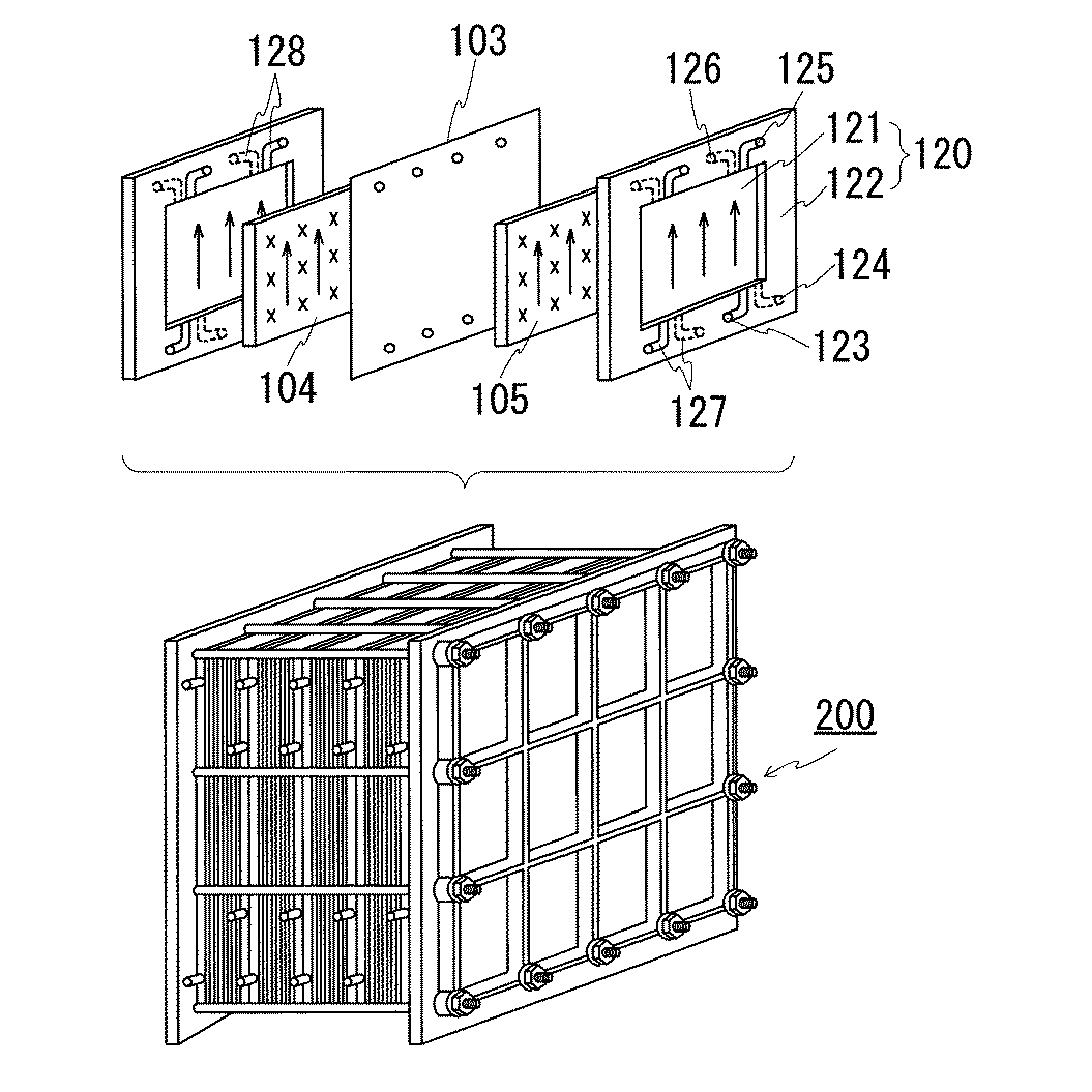
上記のようなレドックスフロー電池では、通常、複数のセルを積層させたセルスタック200と呼ばれる構成が利用される。図5は、セルスタックの概略構成図である。上記セルとしてセルフレーム120を用いた構成が知られている。セルフレーム120は、一面に正極電極104が接するように配置され、他面に負極電極105が接するように配置される双極板121と、その外周に形成されるフレーム枠122とを具える。フレーム枠122には、各極電極104,105に各極電解液を供給する給液用マニホールド123,124と、各極電極104,105からの電解液を排出する排液用マニホールド125,126とが形成され、これらマニホールド123,124,125,126は、複数のセルフレーム120を積層することで電解液の流路を構成し、供給側輸送路(図4参照)、排出側輸送路(同)に接続される。また、フレーム枠122においてマニホールド123,124,125,126と双極板121との間にはそれぞれ、電解液が流通されるスリット127,128が設けられている。セルスタック200は、セルフレーム120,正極電極104,隔膜103,負極電極105,セルフレーム120,…と順に繰り返し積層されて構成される。
In the redox flow battery as described above, a configuration called a
その他、レドックスフロー電池システムでは、セルの電圧を測定する電圧計、充放電時の電流値を測定する電流計、電解液の輸送圧力を測定する圧力計、電解液の温度を測定する温度計などの計測機器、これら計測機器を制御する制御装置などを具えることが多い。作業者又は制御装置は、これら計測機器の測定結果によりシステムの状態を把握し、電圧や電流、圧力、温度などが所定値となるように制御したり、メンテナンスを行ったりしている。また、レドックスフロー電池システムとして、外部電力系統との間で充放電を行うセルとは別にモニタセルを具えるものがあり、このモニタセルにて電圧などを検出し、この検出結果を利用して、運転を制御することなどが行われている。特許文献1には、交流/直流変換器に接続されない補助セル(モニタセル)を主セルと一体に具えたレドックスフロー電池システムが開示されており、このシステムでは、補助セルにて回路電圧を測定し、この回路電圧に基づいて主セルの充電停止や放電停止を決定することで、主セルの出力容量の安定を図っている。特許文献2,3には、主セルと電解液を共通する検出用セル(モニタセル)を主セルと別個に具えたレドックスフロー電池システムが開示されており、特許文献2に記載のシステムでは、検出用セルにて一定時間低電流で放電して、この放電電圧変化の傾きにより主セルの電池容量を検出し、電池容量の低下の原因が調べられるようにしている。特許文献3に記載のシステムでは、モニタセルの電極を分析することで、主セルの電極の劣化状態を把握できるようにしている。
In addition, in a redox flow battery system, a voltmeter that measures the voltage of a cell, an ammeter that measures the current value during charge and discharge, a pressure gauge that measures the transport pressure of the electrolyte, a thermometer that measures the temperature of the electrolyte, etc. In many cases, the measuring instrument and a control device for controlling the measuring instrument are provided. The operator or the control device grasps the state of the system based on the measurement results of these measuring devices, and controls the voltage, current, pressure, temperature, and the like to be predetermined values and performs maintenance. In addition, some redox flow battery systems include a monitor cell in addition to a cell that charges and discharges with an external power system. The monitor cell detects voltage and uses this detection result for operation. And so on.
上述のように従来のレドックスフロー電池システムでは、セルやモニタセルにて電圧を測定するなどして、この測定結果に基づき、運転の制御やメンテナンスなどが行われている。しかし、従来のレドックスフロー電池システムでは、隔膜や双極板といったセルの内部構成部材が破損されているか否かをより確実に把握することができない、という問題がある。 As described above, in the conventional redox flow battery system, voltage is measured by a cell or a monitor cell, and operation control or maintenance is performed based on the measurement result. However, in the conventional redox flow battery system, there is a problem that it is not possible to more reliably grasp whether or not the internal components of the cell such as the diaphragm and the bipolar plate are damaged.
隔膜や双極板は、フレーム枠などと比較して軟質な材料で形成されていることが多く、破れたりすることがある。これら隔膜や双極板が破損すると、セル内で正負極の電解液が混合され、自己放電が生じたり、セル内の温度が過度に上昇するなどの不具合が生じてしまう。従って、隔膜や双極板の破損の有無は、なるべく早期に発見できることが望まれる。しかし、隔膜や双極板は、フレーム枠間やフレーム枠の外周縁よりも内周側に配置されるため、これらの破損は、セル(セルスタック)の外観から目視にて確認することが困難である。 The diaphragm and the bipolar plate are often made of a softer material than the frame or the like, and may be torn. When these diaphragms and bipolar plates are damaged, positive and negative electrode electrolytes are mixed in the cell, causing problems such as self-discharge and excessive increase in the temperature in the cell. Therefore, it is desirable that the presence or absence of damage to the diaphragm or the bipolar plate can be detected as early as possible. However, since the diaphragm and bipolar plate are arranged between the frame frames and on the inner peripheral side of the outer peripheral edge of the frame frame, it is difficult to visually check the damage from the appearance of the cell (cell stack). is there.
一方、上記のように隔膜や双極板が破損すると、電解液の混合による温度の上昇や自己放電によるセル電圧の低下などの変化が生じる。従って、従来のシステムでも、電解液の温度やセル電圧などにより隔膜や双極板の破損を確認できないこともない。しかし、電解液の温度上昇やセル電圧の低下は、隔膜や双極板の破損以外の原因でも生じるため、これらの事象では、破損の有無を正確に判断しにくい。 On the other hand, when the diaphragm or the bipolar plate is damaged as described above, changes such as an increase in temperature due to mixing of the electrolyte and a decrease in cell voltage due to self-discharge occur. Therefore, even in the conventional system, it is not possible to confirm the breakage of the diaphragm or the bipolar plate due to the temperature of the electrolyte or the cell voltage. However, since the rise in the temperature of the electrolyte and the decrease in the cell voltage are caused by causes other than the breakage of the diaphragm and the bipolar plate, it is difficult to accurately determine the presence or absence of breakage in these events.
また、従来のレドックスフロー電池システムにおいて主セルと別にモニタセルを具える場合、モニタセルには、主セルと同じ正極電解液及び負極電解液の双方が供給される。即ち、主セルに供給される正極電解液をモニタセルにおいても正極電解液として供給され、主セルに供給される負極電解液をモニタセルにおいても負極電解液として供給される。従って、このように主セルと同じように正極電解液及び負極電解液が循環供給されるモニタセルでは、やはり隔膜や双極板の破損を的確に認識することが難しい。 Further, when the conventional redox flow battery system includes a monitor cell separately from the main cell, both the positive electrode electrolyte and the negative electrode electrolyte that are the same as the main cell are supplied to the monitor cell. That is, the positive electrode electrolyte supplied to the main cell is also supplied as the positive electrode electrolyte in the monitor cell, and the negative electrode electrolyte supplied to the main cell is also supplied as the negative electrode electrolyte in the monitor cell. Therefore, in the monitor cell in which the positive electrode electrolyte and the negative electrode electrolyte are circulated and supplied in the same manner as the main cell, it is still difficult to accurately recognize the breakage of the diaphragm and the bipolar plate.
そこで、本発明の主目的は、セルの内部構成部材の状態をより的確に確認することができるレドックスフロー電池システムを提供することにある。また、本発明の他の目的は、このレドックスフロー電池システムを用いて、セルを構成する内部構成部材の破損の有無を調べるのに適したレドックスフロー電池システムの運転方法を提供することにある。 Then, the main objective of this invention is to provide the redox flow battery system which can confirm the state of the internal structural member of a cell more exactly. Another object of the present invention is to provide a method for operating a redox flow battery system suitable for examining the presence / absence of breakage of internal components constituting the cell using the redox flow battery system.
本発明者は、セルの構成部材のうち隔膜や双極板などといった外観から確認しにくい内部構成部材の状態、具体的には破損の有無をより的確に確認するべく種々検討した。その結果、隔膜などの破損により、セル内にて正負の電解液が混合したり自己放電したりすると、自己放電を含む電池反応が行われた後にセルから排出される充電状態又は放電状態の電解液のイオン濃度が所定濃度から変化する、特に、充電状態のイオン濃度が所定濃度よりも低くなることに着目した。レドックスフロー電池システムでは、充電電解液のイオン濃度と、セルに供給する電解液の流量と、電解液の充放電電流値を電解液の流量で除した(充放電電流値/流量)いわゆる変換率とを予め設定し、イオン濃度や流量、変換率が設定範囲となるように制御することが一般的に行われている。レドックスフロー電池システムを構築する構成部材に異常が生じたり、構成部材が経年劣化したりしていない状態(例えば、システム構築初期など)では、上記設定範囲を十分に維持することができ、良好な状態で充放電を行うことができる。従って、上記異常などが生じていない状態の場合、タンクからセルに供給される電解液は、セル内にて電池反応を行い、設定された変換率に基づき一定範囲内の充放電イオン濃度に変化した状態でセルから排出される。即ち、タンクからセルに供給される電池反応を行っていない電解液のイオン濃度と、セルにて電池反応が行われた後にセルから排出された電解液のイオン濃度との差が設定範囲に維持される。しかし、特に、隔膜や双極板が破損するといった異常が生じた場合、上述のように自己放電により、セルから排出された電解液のイオン濃度が変化する。そこで、本発明者は、イオン濃度の変化を調べれば、隔膜や双極板の状態をより的確に確認することができると考え、イオン濃度の変化を検出することを検討した。そして、セルに供給される電池反応を行う前の電解液とセルから排出された電池反応を行った後の電解液とが供給されるモニタセルを構築した場合、上記イオン濃度の変化は、このモニタセルのセル電圧におおよそ比例するとの知見を得た。 The present inventor has made various studies in order to more accurately confirm the state of internal structural members that are difficult to confirm from the appearance, such as a diaphragm and a bipolar plate, among the structural members of the cell, specifically, the presence or absence of breakage. As a result, when the positive and negative electrolytes are mixed or self-discharged in the cell due to damage to the diaphragm or the like, the charged or discharged electrolysis discharged from the cell after the battery reaction including self-discharge is performed It was noted that the ion concentration of the liquid changes from a predetermined concentration, in particular, the ion concentration in the charged state is lower than the predetermined concentration. In the redox flow battery system, the ion concentration of the charging electrolyte, the flow rate of the electrolyte supplied to the cell, and the charge / discharge current value of the electrolyte divided by the flow rate of the electrolyte (charge / discharge current value / flow rate), so-called conversion rate Are generally controlled so that the ion concentration, flow rate, and conversion rate fall within a set range. In a state where the components constituting the redox flow battery system are not abnormal or have not deteriorated over time (for example, at the initial stage of system construction), the above setting range can be sufficiently maintained and good. Charging / discharging can be performed in a state. Therefore, in the state where the above abnormality does not occur, the electrolyte supplied from the tank to the cell undergoes a battery reaction in the cell and changes to a charge / discharge ion concentration within a certain range based on the set conversion rate. In this state, it is discharged from the cell. That is, the difference between the ionic concentration of the electrolyte that is not performing the battery reaction supplied from the tank to the cell and the ionic concentration of the electrolytic solution that is discharged from the cell after the battery reaction is maintained in the cell is maintained within the set range. Is done. However, particularly when an abnormality such as breakage of the diaphragm or the bipolar plate occurs, the ion concentration of the electrolyte discharged from the cell changes due to self-discharge as described above. Therefore, the present inventor considered that the state of the diaphragm and the bipolar plate can be more accurately confirmed by examining the change in the ion concentration, and studied to detect the change in the ion concentration. And when the monitor cell to which the electrolyte solution before performing the battery reaction supplied to the cell and the electrolyte solution after performing the battery reaction discharged from the cell is constructed, the change in the ion concentration is It was found that the cell voltage was roughly proportional to the cell voltage.
セルに供給されるセル内で電池反応が行われる前の電解液及びセル内で電池反応が行われた後にセルから排出された電解液が供給されるモニタセルを考える。
気体定数:R(J/K・mol)≒8.3
絶対温度:T(K)
ファラデー定数:F(c/mol)≒9.6×104
全イオン濃度(充電+放電):n0(mol/リットル)
セル内で電池反応が行われる前の充電電解液のイオン濃度:n(mol/リットル)
セル内で電池反応が行われる前の充電電解液のイオン濃度とセル内で電池反応が行われた後の充電電解液のイオン濃度との差:Δn(mol/リットル)
とする。このとき、放電電解液のイオン濃度は、n0-n(mol/リットル)、電池反応後の充電電解液のイオン濃度は、n+Δnと表わされる。
充電電解液のイオン濃度:n(mol/リットル)の標準起電力をE(n)、充電電解液のイオン濃度:n+Δn(mol/リットル)の標準起電力をE(n+Δn)、n=0.5×n0のときの標準起電力をE0とすると、ネルンストの式から、E(n),E(n+Δn)は以下の式で表わされる。そして、モニタセルの電圧ΔEは、ΔE=E(n+Δn)-E(n)で表わされる。
Let us consider an electrolyte solution before the battery reaction is performed in the cell supplied to the cell and a monitor cell to which the electrolyte solution discharged from the cell after the battery reaction is performed in the cell.
Gas constant: R (J / K ・ mol) ≒ 8.3
Absolute temperature: T (K)
Faraday constant: F (c / mol) ≒ 9.6 × 10 4
Total ion concentration (charge + discharge): n 0 (mol / liter)
Ion concentration of the charging electrolyte before battery reaction takes place in the cell: n (mol / liter)
Difference between ion concentration of charging electrolyte before battery reaction in cell and ion concentration of charging electrolyte after battery reaction in cell: Δn (mol / liter)
And At this time, the ion concentration of the discharge electrolyte is expressed as n 0 -n (mol / liter), and the ion concentration of the charge electrolyte after the battery reaction is expressed as n + Δn.
Ion concentration of the charging electrolyte: n (mol / liter) standard electromotive force E (n), Ion concentration of the charging electrolyte: n + Δn (mol / liter) standard electromotive force E (n + Δn), Assuming that the standard electromotive force when n = 0.5 × n 0 is E 0 , E (n) and E (n + Δn) are expressed by the following equations from the Nernst equation. The voltage ΔE of the monitor cell is expressed by ΔE = E (n + Δn) −E (n).
上記式において(R・T)/Fは定数であるから(T=300Kとするとき、約0.258)、この近似式より、セル電圧ΔEは、イオン濃度の差分Δnにほぼ比例するといえる。そこで、本発明者は、主セルに供給される電池反応が行われる前の電解液を一方の極の電解液とし、電池反応が行われた後に主セルから排出された電解液を他方の極の電解液として供給されるモニタセル、即ち、これら電解液が正負極の電解液として機能されるモニタセルを構築し、このモニタセルのセル電圧を測定して、主セルに供給される充電電解液のイオン濃度とセルから排出された充電電解液のイオン濃度との差Δn(=I0/(F・q)、充電電流値:I0(A)、電解液の流量:q(リットル/sec))と測定したセル電圧ΔEとの関係を調べた。ここでは、主セルに供給する充電電解液のイオン濃度(n)と、上記差分Δnとから変換率(χ=Δn/n)を求めて、セル電圧と変換率との関係を調べた。その結果、図3のグラフに示すように、セル電圧ΔEと変換率χとがほぼ比例関係にある、即ち、セル電圧ΔEと差分Δnとがほぼ比例関係にあることが確認された。従って、上記モニタセルを構築し、このモニタセルのセル電圧の変化(増減)を確認することで、イオン濃度の変化を判断することができ、この結果から隔膜や双極板の状態をより的確に判断することができる。より具体的には、隔膜や双極板に破損が生じた場合、イオン濃度が低下するため、セル電圧が低下する。従って、セル電圧が低下した場合、隔膜や双極板に破損が生じていると判断することができる。この知見に基づき、本発明は、セルの内部構成部材の状態をより直接的に把握することができるモニタセルを具えることを規定する。具体的には、本発明は、電解液が循環供給され、外部電力系統との間で充放電を行う主セルと、この主セルに接続されるモニタセルとを具えるレドックスフロー電池システムである。そして、本発明の最も特徴とするところは、上記モニタセルに循環供給する電解液として、主セルにて電池反応が行われる前の供給側電解液と、主セルにて電池反応が行われた後の排出側電解液とを用いるところにある。以下、本発明をより詳しく説明する。 In the above equation, (R · T) / F is a constant (about 0.258 when T = 300K). From this approximation, it can be said that the cell voltage ΔE is substantially proportional to the difference Δn in ion concentration. Therefore, the present inventor uses the electrolyte before the battery reaction to be supplied to the main cell as the electrolyte of one electrode, and the electrolyte discharged from the main cell after the battery reaction as the other electrode. The monitor cell supplied as the electrolyte solution, that is, the monitor cell in which these electrolyte solutions function as the positive and negative electrolyte solutions, the cell voltage of this monitor cell is measured, and the ions of the charged electrolyte solution supplied to the main cell Δn (= I 0 / (F · q), charging current value: I 0 (A), electrolyte flow rate: q (liter / sec)) between the concentration and the ionic concentration of the charging electrolyte discharged from the cell) And the measured cell voltage ΔE were examined. Here, the conversion rate (χ = Δn / n) was obtained from the ion concentration (n) of the charging electrolyte supplied to the main cell and the difference Δn, and the relationship between the cell voltage and the conversion rate was examined. As a result, as shown in the graph of FIG. 3, it was confirmed that the cell voltage ΔE and the conversion rate χ are substantially proportional, that is, the cell voltage ΔE and the difference Δn are substantially proportional. Therefore, by constructing the monitor cell and confirming the change (increase / decrease) in the cell voltage of the monitor cell, it is possible to determine the change in the ion concentration, and from this result, more accurately determine the state of the diaphragm and the bipolar plate be able to. More specifically, when the diaphragm or the bipolar plate is damaged, the ion concentration is lowered, so that the cell voltage is lowered. Therefore, when the cell voltage decreases, it can be determined that the diaphragm or the bipolar plate is damaged. Based on this knowledge, the present invention provides that a monitor cell is provided that can more directly grasp the state of the internal components of the cell. Specifically, the present invention is a redox flow battery system including a main cell that is circulated and supplied with an electrolytic solution and charges and discharges with an external power system, and a monitor cell connected to the main cell. The most characteristic feature of the present invention is that, as an electrolytic solution that is circulated and supplied to the monitor cell, a supply-side electrolytic solution before the battery reaction is performed in the main cell and a battery reaction that is performed in the main cell The discharge side electrolyte solution is used. Hereinafter, the present invention will be described in more detail.
レドックスフロー電池システムの代表的な構成としては、セルと、セルに供給される又はセルから排出される電解液を貯留するタンクと、セルとタンクとの間を連結する電解液の輸送路と、セルに電解液を循環するために輸送路に設けられるポンプとを具える構成が挙げられる。セルには、交流/直流変換器が接続され、この交流/直流変換器を介して外部電力系統が接続される。外部電力系統としては、充電時、セルに電力を供給する充電電力源となる発電所などの発電設備や、放電時、セルの放電対象となる需要家などの外部負荷といったものが挙げられる。このような構成を本発明レドックスフロー電池システムの基本的構成として利用してもよい。また、本発明システムにおいて利用する電解液は、1.起電力が高く、2.エネルギー密度が大きく、3.電解液が単一元素系であるため正極電解液と負極電解液とが混合しても充電によって再生することができるといった多くの利点を有しているバナジウムイオン溶液が好適である。 As a typical configuration of the redox flow battery system, a cell, a tank for storing an electrolyte supplied to the cell or discharged from the cell, an electrolyte transportation path connecting between the cell and the tank, The structure provided with the pump provided in a conveyance path in order to circulate electrolyte solution to a cell is mentioned. An AC / DC converter is connected to the cell, and an external power system is connected via the AC / DC converter. Examples of the external power system include a power generation facility such as a power plant that serves as a charging power source that supplies power to the cell during charging, and an external load such as a consumer that is subject to discharge of the cell during discharge. Such a configuration may be used as a basic configuration of the redox flow battery system of the present invention. In addition, the electrolytic solution used in the system of the present invention is 1. Electromotive force is high, 2. Energy density is large, 3. Since the electrolytic solution is a single element system, the positive electrode electrolyte and the negative electrode electrolyte are mixed. A vanadium ion solution having many advantages such that it can be regenerated by charging is also preferred.
セルは、イオンが通過可能な隔膜により分離される正極セルと負極セルとを具える構成が代表的である。正極セル及び負極セルはそれぞれ、正極電極、負極電極を内蔵する。このようなセルは、一面に正極電極、他面に負極電極が接触配置される双極板と、この双極板の外周に設けられるフレーム枠とを具えるセルフレームを用いて構成することができる。具体的には、順に、セルフレーム、正極電極、隔膜、負極電極、セルフレームを積層させることでセルが構成される。このとき、セルフレーム(双極板)の一面と正極電極と隔膜の一面とで正極セルが構成され、隔膜の他面と負極電極とセルフレーム(双極板)の他面とで負極セルが構成される。 The cell typically includes a positive electrode cell and a negative electrode cell separated by a diaphragm through which ions can pass. Each of the positive electrode cell and the negative electrode cell incorporates a positive electrode and a negative electrode. Such a cell can be configured by using a cell frame including a bipolar plate having a positive electrode on one surface and a negative electrode on the other surface and a frame frame provided on the outer periphery of the bipolar plate. Specifically, a cell is configured by sequentially stacking a cell frame, a positive electrode, a diaphragm, a negative electrode, and a cell frame. At this time, a positive electrode cell is composed of one surface of the cell frame (bipolar plate), the positive electrode and one surface of the diaphragm, and a negative electrode cell is composed of the other surface of the diaphragm, the negative electrode and the other surface of the cell frame (bipolar plate). The
隔膜は、イオンが透過できるイオン交換膜を利用するとよい。各極電極は、例えば、カーボンフェルト製のものが挙げられる。双極板は、例えば、プラスチックカーボン製のものが挙げられる。フレーム枠は、電解液が接触しても短絡などの事故が生じないように絶縁材料、例えば、塩化ビニルなどの樹脂製のものが挙げられる。また、フレーム枠は、各極電解液を貯留するタンクから各電極に各極電解液を供給する供給用マニホールドと、各電極から各極電解液を排出する排出用マニホールドと、供給用マニホールドを通過した電解液を電極に輸送し易いように、かつ電極から排出用マニホールドに電解液を輸送し易いように、マニホールドと双極板との間に設けられたスリットとを具えるものが挙げられる。電解液の輸送路は、電解液が接触しても短絡などの事故が生じないように絶縁材料、例えば、塩化ビニルなどの樹脂にて形成されたパイプ(配管)などを利用して形成するとよい。 The diaphragm may be an ion exchange membrane that can transmit ions. Examples of each electrode include those made of carbon felt. Examples of the bipolar plate include those made of plastic carbon. The frame frame is made of an insulating material, for example, a resin such as vinyl chloride so that an accident such as a short circuit does not occur even when the electrolytic solution contacts. The frame frame passes through a supply manifold for supplying each electrode electrolyte from a tank for storing each electrode electrolyte to each electrode, a discharge manifold for discharging each electrode electrolyte from each electrode, and a supply manifold. In order to facilitate the transportation of the electrolytic solution to the electrode and to facilitate the transportation of the electrolytic solution from the electrode to the discharge manifold, there may be mentioned one provided with a slit provided between the manifold and the bipolar plate. The electrolytic solution transport path should be formed using a pipe (pipe) made of an insulating material, for example, a resin such as vinyl chloride, so that an accident such as a short circuit does not occur even when the electrolytic solution contacts. .
そして、本発明レドックスフロー電池システムでは、利用目的の異なる2種類のセル、具体的には、主セルとモニタセルとを具える。主セルは、交流/直流変換器を介して、充電電力源となる発電所など及び放電対象となる需要家などと接続され、充放電を行うのに用いられる電池本体を構成するセルである。このような主セルは、上記構成のセルを一つ具える単セル構造としてもよいし、上記構成のセルを複数積層した積層体(セルスタック)を構築して利用してもよい。通常、主セルは、セルスタックで利用されることが多い。 The redox flow battery system of the present invention includes two types of cells having different purposes of use, specifically, a main cell and a monitor cell. The main cell is a cell that constitutes a battery body that is connected to a power plant that is a charging power source and a consumer that is a discharge target through an AC / DC converter, and is used for charging and discharging. Such a main cell may have a single cell structure including one cell having the above-described configuration, or may be used by constructing a stacked body (cell stack) in which a plurality of cells having the above-described configuration are stacked. Usually, the main cell is often used in a cell stack.
一方、モニタセルは、主セルと同様に上記構成のセルからなり、主セルの状態を確認するのに用いられる検査用セルであり、主セルのように交流/直流変換器に接続されて外部電力系統を対象として充放電を行うために用いられない。特に、本発明では、モニタセルにて隔膜や双極板といった主セルの内部構成部材の健全性をより的確に確認するべく、モニタセルに供給する電解液を主セルと異ならせる。 On the other hand, the monitor cell is composed of cells having the above-described configuration, similar to the main cell, and is a test cell used to check the state of the main cell. Like the main cell, the monitor cell is connected to an AC / DC converter and connected to external power. It is not used to charge and discharge the system. In particular, in the present invention, the electrolyte supplied to the monitor cell is different from that of the main cell in order to more accurately confirm the soundness of the internal components of the main cell such as the diaphragm and the bipolar plate in the monitor cell.
具体的には、電解液としてバナジウムイオン溶液を用いる場合、主セルには、一般的に用いられている正極電解液及び負極電解液を供給する。バナジウムイオン溶液を用いた正極電解液としては、5価のバナジウムイオン(V5+)のイオン濃度が高い5価のバナジウムイオン溶液、負極電解液としては、2価のバナジウムイオン(V2+)のイオン濃度が高い2価のバナジウムイオン溶液が一般に用いられる。従って、主セルには、5価のバナジウムイオン溶液を正極電解液として供給し、2価のバナジウムイオン溶液を負極電解液として供給する。 Specifically, when a vanadium ion solution is used as the electrolytic solution, a commonly used positive electrode electrolyte and negative electrode electrolyte are supplied to the main cell. As a positive electrode electrolyte using a vanadium ion solution, a pentavalent vanadium ion solution having a high ion concentration of pentavalent vanadium ions (V 5+ ), and as a negative electrode electrolyte, divalent vanadium ions (V 2+ ) Generally, a divalent vanadium ion solution having a high ion concentration is used. Therefore, a pentavalent vanadium ion solution is supplied to the main cell as a positive electrode electrolyte, and a divalent vanadium ion solution is supplied as a negative electrode electrolyte.
これに対し、本発明システムにおけるモニタセルには、主セルと同様にバナジウムイオン溶液を用いるが、いずれか一極の電解液のみを用いて、この電解液を正極及び負極として機能させる。従来のレドックスフロー電池システムにおいてモニタセルを具える場合、主セルで正極電解液及び負極電解液として用いられている電解液をモニタセルにおいてもそのまま供給させている。即ち、従来のシステムにおけるモニタセルは、電解液の流通形態をも主セルと同様の構成としており、主セルで正極電解液として用いられている電解液をモニタセルに対しても正極電解液として供給し、主セルで負極電解液として用いられている電解液をモニタセルに対しても負極電解液として供給する。これに対し、本発明システムにおけるモニタセルは、主セルにおけるいずれか一極の電解液を正極側電解液、負極側電解液として供給させる構成とする。具体的には、本発明システムにおけるモニタセルは、タンクから主セルに供給される一極の電解液において、主セルにて電池反応が行われる前の供給側電解液と、主セルにて電池反応が行われた後に主セルから排出された排出側電解液とを正極側電解液、負極側電解液として供給させる。例えば、主セルに供給する両極電解液としてバナジウムイオン溶液を用いており、そのうちいわゆる一般的な正極電解液(5価のバナジウムイオン溶液)を本発明システムにおけるモニタセルに供給する電解液とし、この電解液によりモニタセルで電池を形成することができる。この場合、主セルにより電池反応が行われていない供給側電解液は、5価のバナジウムイオン(V5+)のイオン濃度が高いためモニタセルにおいて正極の電解液として機能し、主セルにて電池反応が行われた後、主セルから排出された排出側電解液は、5価のバナジウムイオン(V5+)のイオン濃度が主セルに供給する前と比較して低下しているためモニタセルにおいて負極の電解液として機能する。また、主セルに供給する両極電解液としてバナジウムイオン溶液を用いており、そのうちいわゆる一般的な負極電解液(2価のバナジウムイオン溶液)を本発明システムにおけるモニタセルに供給する電解液とし、この電解液によりモニタセルで電池を形成することもできる。この場合、主セルにより電池反応が行われていない供給側電解液は、2価のバナジウムイオン(V2+)のイオン濃度が高いためモニタセルにおいて負極の電解液として機能し、主セルにて電池反応が行われた後、主セルから排出された排出側電解液は、2価のバナジウムイオン(V2+)のイオン濃度が供給前と比較して低下しているためモニタセルにおいて正極の電解液として機能する。 On the other hand, a vanadium ion solution is used for the monitor cell in the system of the present invention as in the main cell, but only one of the electrolytes is used, and this electrolyte functions as a positive electrode and a negative electrode. When the monitor cell is provided in the conventional redox flow battery system, the electrolyte used as the positive electrode electrolyte and the negative electrode electrolyte in the main cell is also supplied as it is in the monitor cell. In other words, the monitor cell in the conventional system has the same configuration as the main cell in the flow mode of the electrolyte solution, and supplies the electrolyte solution used as the cathode electrolyte solution in the main cell to the monitor cell as the cathode electrolyte solution. The electrolyte used as the negative electrode electrolyte in the main cell is also supplied to the monitor cell as the negative electrode electrolyte. On the other hand, the monitor cell in the system of the present invention is configured to supply any one electrolyte solution in the main cell as the positive electrode side electrolyte solution and the negative electrode side electrolyte solution. Specifically, the monitor cell in the system of the present invention is a unipolar electrolyte supplied from the tank to the main cell, and the supply-side electrolyte before the battery reaction is performed in the main cell and the battery reaction in the main cell. The discharge-side electrolyte discharged from the main cell after the above is supplied as a positive-electrode-side electrolyte and a negative-electrode-side electrolyte. For example, a vanadium ion solution is used as a bipolar electrolyte supplied to the main cell, and a so-called general positive electrode electrolyte (pentavalent vanadium ion solution) is used as an electrolyte supplied to the monitor cell in the system of the present invention. A battery can be formed in the monitor cell by the liquid. In this case, the supply-side electrolyte solution in which the battery reaction is not performed by the main cell has a high ion concentration of pentavalent vanadium ions (V 5+ ), and thus functions as a positive electrode electrolyte in the monitor cell. After the reaction is performed, the discharge side electrolyte discharged from the main cell has a lower concentration of pentavalent vanadium ions (V 5+ ) than before being supplied to the main cell. Functions as a negative electrode electrolyte. In addition, a vanadium ion solution is used as a bipolar electrolyte supplied to the main cell, of which a so-called general negative electrode electrolyte (a divalent vanadium ion solution) is used as an electrolyte supplied to the monitor cell in the system of the present invention. It is also possible to form a battery in the monitor cell with the liquid. In this case, the supply-side electrolyte in which the battery reaction is not performed by the main cell has a high ion concentration of divalent vanadium ions (V 2+ ), and thus functions as a negative electrode electrolyte in the monitor cell. After the reaction is performed, the electrolyte on the discharge side discharged from the main cell has an electrolyte concentration of the positive electrode in the monitor cell because the ion concentration of divalent vanadium ions (V 2+ ) is lower than before supply. Function as.
本発明は、上述のように主セルにおいて一極の電解液として利用される電解液にて正極として機能する電解液及び負極として機能する電解液をつくり、モニタセルに供給する構成である。供給側電解液をモニタセルに供給するには、タンクと主セル間に配置される供給側の輸送路を分岐して、主セルに供給する電解液のうち、一部の電解液がモニタセルに供給されるように構成することが挙げられる。排出側電解液をモニタセルに供給するには、タンクと主セル間に配置される排出側の輸送路を分岐して、主セルから排出された電解液のうち、一部の電解液がモニタセルに供給されるように構成することが挙げられる。モニタセルに接続される電解液の輸送分岐路に別途ポンプを具えて、モニタセルにおける電解液の循環を補助するようにしてもよい。また、輸送分岐路にバルブを設け、電解液の輸送圧力を調整するようにしてもよい。具体的には、バルブの閉める量を多くすることで、輸送圧力を大きくしたり、バルブを開ける量を多くすることで、輸送圧力を小さくする。このようなバルブの開閉により、セルを通過する前の輸送圧力と、セルを通過後の輸送圧力とが同等になるように調整することができる。 As described above, the present invention has a configuration in which an electrolytic solution that functions as a positive electrode and an electrolytic solution that functions as a negative electrode are prepared and supplied to a monitor cell by using an electrolytic solution that is used as a monopolar electrolytic solution in a main cell. In order to supply the supply-side electrolyte to the monitor cell, the supply-side transport path arranged between the tank and the main cell is branched, and some of the electrolyte supplied to the main cell is supplied to the monitor cell. It is mentioned that it is configured as described above. To supply the discharge-side electrolyte to the monitor cell, branch the discharge-side transport path arranged between the tank and the main cell, and some of the electrolyte discharged from the main cell will enter the monitor cell. It is mentioned that it is configured to be supplied. A separate pump may be provided in the electrolyte transport branch connected to the monitor cell to assist the circulation of the electrolyte in the monitor cell. Further, a valve may be provided in the transport branch path to adjust the transport pressure of the electrolytic solution. Specifically, the transportation pressure is reduced by increasing the amount of closing the valve or increasing the transportation pressure or increasing the amount of opening the valve. By opening and closing such a valve, the transport pressure before passing through the cell and the transport pressure after passing through the cell can be adjusted to be equal.
このようなモニタセルは、単セル構造としてもよいし、セルスタックとしてもよい。モニタセルを単セル構造とする場合、後述するモニタセルのセル電圧(起電力)が小さすぎて測定しにくいことがある。このとき、モニタセルは、セルスタックとすることが好ましい。また、モニタセルは、セル電圧が測定できればよく、モニタセルをセルスタックとする場合、積層させるセル数は、主セルよりも少なくしてもよいし、同じセル数とする場合や単セル構造とする場合、主セルよりも小さくしてもよい。 Such a monitor cell may have a single cell structure or a cell stack. When the monitor cell has a single cell structure, the cell voltage (electromotive force) of the monitor cell described later may be too small to measure. At this time, the monitor cell is preferably a cell stack. The monitor cell only needs to be able to measure the cell voltage. When the monitor cell is a cell stack, the number of stacked cells may be less than that of the main cell, the same number of cells, or the single cell structure. It may be smaller than the main cell.
本発明においてモニタセルは、一つの主セルに対し、一つ設けてもよいし、二つ設けてもよい。モニタセルを一つ設ける場合、供給側電解液、排出側電解液に用いる電解液は、主セルに供給される正極電解液、負極電解液のいずれを用いてもよい。モニタセルを二つ設ける場合、一方のモニタセル(第一モニタセル)に用いる供給側電解液、排出側電解液としてそれぞれ、主セルに供給される正極電解液、主セルから排出される正極電解液を用い、他方のモニタセル(第二モニタセル)に用いる供給側電解液、排出側電解液としてそれぞれ、主セルに供給される負極電解液、主セルから排出される負極電解液を用いるとよい。 In the present invention, one monitor cell or two monitor cells may be provided for one main cell. When one monitor cell is provided, any of the positive electrode electrolyte and the negative electrode electrolyte supplied to the main cell may be used as the electrolyte used for the supply side electrolyte solution and the discharge side electrolyte solution. When two monitor cells are provided, the positive electrolyte supplied to the main cell and the positive electrolyte discharged from the main cell are used as the supply-side electrolyte and the discharge-side electrolyte used in one monitor cell (first monitor cell), respectively. The negative electrode electrolyte supplied to the main cell and the negative electrode electrolyte discharged from the main cell may be used as the supply side electrolyte and the discharge side electrolyte used for the other monitor cell (second monitor cell), respectively.
上述のようなモニタセルを少なくとも一つ具える本発明システムを構築し、更に、モニタセルのセル電圧を測定する電圧測定手段を具えてセル電圧を測定することで、この測定結果により主セルの隔膜や双極板の破損の有無をより的確に判断することができる。また、モニタセルを二つ具える本発明システムを構築した場合、主セルに供給する正極電解液、負極電解液に関する情報、例えば、各極における電位上昇度などを別個に得られることになる。この情報は、例えば、主セルに供給する正極電解液と負極電解液との間における流量のバランスの調整に利用することができる。 By constructing the system of the present invention comprising at least one monitor cell as described above, and further comprising a voltage measuring means for measuring the cell voltage of the monitor cell to measure the cell voltage, the measurement results indicate that the main cell diaphragm and The presence or absence of damage to the bipolar plate can be determined more accurately. Further, when the present invention system including two monitor cells is constructed, information on the positive electrode electrolyte and the negative electrode electrolyte supplied to the main cell, for example, the degree of increase in potential at each electrode can be obtained separately. This information can be used, for example, for adjusting the flow rate balance between the positive electrode electrolyte and the negative electrode electrolyte supplied to the main cell.
上記モニタセルを具える本発明システムにて、隔膜や双極板といった主セルの内部構成部材の健全性を調べるにあたり、コンピュータを用いると、簡単に確認することができる。具体的には、記憶、演算、判定、信号の伝送(受信、送信)などの種々の処理を行うことが可能なコンピュータを具え、このコンピュータに以下のステップを有するプログラムを予め入力しておいて以下のステップを行わせることが挙げられる。コンピュータの他、コンピュータのような記憶手段、演算手段、判定手段、信号受信手段、信号送信手段などの種々の処理手段を行えるシーケンサ(プログラマブル・ロジック・コントローラ)などの処理制御装置を利用してもよい。
1. モニタセルに取り付けた電圧測定手段により、モニタセルの電圧を測定するステップ
2. コンピュータに具える比較手段により、測定した電圧と予め設定した設定値とを比較するステップ
3. コンピュータに具える判定手段により、測定電圧と設定値との比較結果に基づき、内部構成部材の異常を判定するステップ
In the system of the present invention including the monitor cell, when checking the soundness of the internal components of the main cell such as the diaphragm and the bipolar plate, it can be easily confirmed by using a computer. Specifically, a computer capable of performing various processes such as storage, calculation, determination, signal transmission (reception and transmission), and a program having the following steps are input in advance to the computer. The following steps may be performed. In addition to a computer, a processing control device such as a sequencer (programmable logic controller) that can perform various processing means such as storage means, computing means, determination means, signal reception means, signal transmission means such as a computer may be used. Good.
1. Step of measuring the voltage of the monitor cell with the voltage measurement means attached to the monitor cell
2. A step of comparing the measured voltage with a preset value by means of comparison provided in the computer
3. A step of determining an abnormality of the internal component based on a comparison result between the measured voltage and the set value by a determination means included in the computer
上記第一ステップを行うにあたり、モニタセルには、電圧の測定手段を取り付けておく。この測定手段とコンピュータとは、測定結果(電気信号)を伝送する配線を介して連結させておく。また、コンピュータには、測定手段からの電気信号が信号受信手段に入力されるようにしておく。 In performing the first step, a voltage measuring means is attached to the monitor cell. The measuring means and the computer are connected via a wiring for transmitting a measurement result (electric signal). Further, the computer is configured so that an electrical signal from the measuring means is input to the signal receiving means.
上記第二ステップを行うにあたり、コンピュータの記憶手段には、予め設定値を入力しておき、コンピュータの比較手段は、記憶手段から呼び出した設定値と信号受信手段が取得した信号(測定電圧)とを比較するようにしておく。 In performing the second step, a setting value is input in advance to the storage means of the computer, and the comparison means of the computer uses the setting value called from the storage means and the signal (measurement voltage) acquired by the signal receiving means. Compare them.
上記第三ステップを行うにあたり、判定手段は、測定電圧が設定値よりも小さいとき、内部構成部材に異常があると判定し、測定電圧が設定値以上のとき、内部構成部材に異常がないと判定するようにしておく。判定結果は、例えば、コンピュータに具える表示手段(モニタ)にて表示されるようにしておき、作業者は、この判定結果を確認することで、内部構成部材の状態を確認することができるようにしてもよい。また、内部構成部材に異常ありと判定された場合、コンピュータは、警告音を出したり、コンピュータに具える表示手段(モニタ)に警告表示を出したりするなどして、内部構成部材の異常を作業者に伝えるようにしてもよい。このような警告を行うことで、作業者は、内部構成部材の異常をより早期に、確実に把握することができる。内部構成部材に異常があった場合、主セルの充放電を停止し、或いは、主セルが充放電を行っていない待機中などで、主セルを構成する隔膜やセルフレームを交換するとよい。 In performing the third step, the determination means determines that there is an abnormality in the internal component when the measurement voltage is smaller than the set value, and there is no abnormality in the internal component when the measurement voltage is equal to or greater than the set value. Make a decision. The determination result is displayed on, for example, a display means (monitor) included in the computer, and the operator can confirm the state of the internal component by confirming the determination result. It may be. In addition, if it is determined that there is an abnormality in the internal component, the computer will work out the abnormality of the internal component by making a warning sound or displaying a warning on the display means (monitor) included in the computer. You may make it tell to a person. By giving such a warning, the operator can surely grasp the abnormality of the internal component member earlier. When there is an abnormality in the internal components, charging / discharging of the main cell may be stopped, or the diaphragm or cell frame constituting the main cell may be replaced while the main cell is not charging / discharging.
モニタセルを二つ具える本発明システムの場合、コンピュータに、両モニタセルから得られた二つのセル電圧に基づき判定を行うようにするとよい。例えば、両セル電圧が設定値以上の場合、内部構成部材に異常がないと判定するとよい。いずれか一方のセル電圧が設定値より小さい場合、内部構成部材に異常が生じていることが考えられるが、主セルに供給される一方の極の電解液の流量が他方の極の電解液の流量よりも大きくなっている、即ち、主セルに供給される電解液の流量にアンバランスが生じていることも考えられる。電解液の流量が大き過ぎると、セルで十分な電池反応を行うことができず、その結果、モニタセルのセル電圧が所定範囲とならないことがある。そこで、内部構成部材の異常か、流量のアンバランスかを調べるべく、いずれか一方のセル電圧が設定値より小さい場合、その判定後、流量の調整を行い、その後、セル電圧を測定して、再度判定を行うことが好ましい。そして、再度行った判定の結果、両セル電圧が設定値以上の場合、内部構成部材に異常なしと判定し、いずれか一方のセル電圧が設定値より小さい場合、内部構成部材に異常ありと判定するとよい。 In the case of the system of the present invention having two monitor cells, it is preferable to make a determination based on two cell voltages obtained from both monitor cells. For example, when both cell voltages are equal to or higher than a set value, it may be determined that there is no abnormality in the internal components. If any one of the cell voltages is smaller than the set value, there may be an abnormality in the internal component, but the flow rate of the electrolyte solution supplied to the main cell is the same as that of the electrolyte solution of the other electrode. It is also conceivable that the flow rate is larger than the flow rate, that is, the flow rate of the electrolyte supplied to the main cell is unbalanced. When the flow rate of the electrolytic solution is too large, a sufficient battery reaction cannot be performed in the cell, and as a result, the cell voltage of the monitor cell may not be within a predetermined range. Therefore, in order to check whether the internal component member is abnormal or the flow rate is unbalanced, if any one of the cell voltages is smaller than the set value, the flow rate is adjusted after the determination, and then the cell voltage is measured, It is preferable to perform the determination again. As a result of the determination performed again, if both cell voltages are equal to or higher than the set value, it is determined that there is no abnormality in the internal component, and if any one of the cell voltages is smaller than the set value, it is determined that the internal component is abnormal. Good.
両セル電圧が設定値より小さい場合、内部構成部材に異常が生じていると考えられる。従って、異常ありとの判定を行ってもよいが、主セルに供給される両極の電解液の流量が共に大き過ぎることで、モニタセルのセル電圧が所定範囲とならないことも考えられる。そこで、上記と同様に両セル電圧が設定値より小さい場合も、判定後に流量の調整を行い、その後、再度判定を行うことが好ましい。そして、再度行った判定の結果、両セル電圧が設定値以上の場合、内部構成部材に異常なしと判定し、両セル電圧が設定値より小さい場合、内部構成部材に異常ありと判定するとよい。 When both cell voltages are smaller than the set value, it is considered that an abnormality has occurred in the internal component. Therefore, it may be determined that there is an abnormality, but it is also conceivable that the cell voltage of the monitor cell does not fall within a predetermined range because the flow rates of the electrolytes in both electrodes supplied to the main cell are both too large. Therefore, it is preferable to adjust the flow rate after the determination, and then perform the determination again after the determination, even when both the cell voltages are smaller than the set value as described above. As a result of the determination performed again, if both cell voltages are equal to or higher than the set value, it is determined that there is no abnormality in the internal component member, and if both cell voltages are smaller than the set value, it is preferable to determine that the internal component member is abnormal.
上記構成を具える本発明レドックスフロー電池システムは、主セルを解体することなく、外観から目視で確認しにくい隔膜や双極板といった主セルの内部構成部材の状態をより的確に確認することができる。また、このようなレドックスフロー電池システムに本発明運転方法を適用することで、内部構成部材の破損の有無を簡単に、より確実に確認することができる。 The redox flow battery system of the present invention having the above configuration can more accurately confirm the state of internal components of the main cell such as a diaphragm and a bipolar plate that are difficult to visually confirm from the outside without disassembling the main cell. . Further, by applying the operation method of the present invention to such a redox flow battery system, it is possible to easily and more surely confirm whether or not the internal structural member is damaged.
以下、本発明の実施の形態を説明する。
図1は、本発明レドックスフロー電池システムの概略構成図である。このレドックスフロー電池システムは、主セル1と、主セル1に供給/排出される正極電解液を貯留する正極電解液タンク10と、主セル1に供給/排出される負極電解液を貯留する負極電解液タンク11と、主セルと各タンク10,11間を連結して電解液を輸送する供給側輸送路12,13及び排出側輸送路14,15と、主セル1に電解液を循環供給するために供給側輸送路12,13に配置されるポンプ16,17とを具える。
Embodiments of the present invention will be described below.
FIG. 1 is a schematic configuration diagram of a redox flow battery system of the present invention. This redox flow battery system includes a
本例において主セル1は、レドックスフロー電池用のセルを複数積層させた積層体(セルスタック)を用いた。セルの具体的な構成は、図4,5に示すものと同様であり、プラスチックカーボン製の双極板とこの双極板の外周に設けられる塩化ビニル製のフレーム枠とからなるセルフレーム、カーボンフェルト製の正極電極、イオン交換膜からなる隔膜、カーボンフェルト製の負極電極、上記と同様のセルフレームを順に積層させて形成している。フレーム枠には、電解液を電極に供給する供給用マニホールド、電極から電解液を排出する排出用マニホールド、双極板とマニホールド間に設けられるスリットとを具える。輸送路12〜15は、塩化ビニル製のパイプにて形成している。また、本例では、正極電解液として5価のバナジウムイオン(V5+)溶液、負極電解液として2価のバナジウムイオン(V2+)溶液を用いた。主セル1は、交流/直流変換器(図4参照)が接続され、この交流/直流変換器を介して、発電所などの充電電力源や需要家などの放電対象といった外部電力系統が接続され、これら外部電力系統に対して充放電を行う。
In this example, the
上記レドックスフロー電池システムには、主セル1以外にモニタセル2p,2nを具える。そして、これらモニタセル2p,2nは、従来のシステムと異なり、主セル1で正極電解液として用いられている5価のバナジウムイオン溶液、主セル1で負極電解液として用いられている2価のバナジウムイオン溶液を主セル1と同様に正極電解液、負極電解液としない。モニタセル2pは、主セル1で正極電解液として利用される電解液のみが供給されて電池を形成し、モニタセル2nには、主セル1で負極電解液として利用される電解液のみが供給されて電池を形成する。より具体的には、モニタセル2p(第一モニタセル)は、主セル1にて電池反応が行われる前の正極電解液(供給側電解液)と、主セル1にて電池反応が行われた後に主セル1から排出された正極電解液(排出側電解液)とが供給される構成である。モニタセル2n(第二モニタセル)は、主セル1にて電池反応が行われる前の負極電解液(供給側電解液)と、主セル1にて電池反応が行われた後に主セル1から排出された負極電解液(排出側電解液)とが供給される構成である。このようにモニタセル2p,2nはそれぞれ、主セル1に供給されるいずれか一極の電解液のみが供給される構成である。モニタセル2pでは、タンク10から供給されて主セル1にて電池反応が行われる前の正極電解液を正極側電解液とし、主セル1にて電池反応が行われた後の正極電解液を負極側電解液として電池を形成する。モニタセル2nでは、タンク11から供給されて主セル1にて電池反応が行われる前の負極電解液を負極側電解液とし、主セル1にて電池反応が行われた後の負極電解液を正極側電解液として電池を形成する。
The redox flow battery system includes
モニタセル2p,2nの基本的構成は、主セル1と同様であり、主セル1とセルの積層数のみが異なる。本例では、モニタセル2p,2nの積層数を主セル1の積層数よりも少なくしている。また、タンク10から供給側輸送路12を経て主セル1に供給される正極電解液、即ち、主セル1において電池反応を行っていない正極電解液がモニタセル2pの正極側に供給されるように供給側輸送路12に分岐路(供給側分岐路20)を設けている。主セル1から排出側輸送路14を経てタンク10に排出される正極電解液、即ち、主セル1において電池反応が行われた正極電解液がモニタセル2pの負極側に供給されるように排出側輸送路14に分岐路(排出側分岐路21)を設けている。また、排出側輸送路14には、モニタセル2pから排出される電解液がタンク10に戻されるように排出路22が接続される。同様に、タンク11から供給側輸送路13を経て主セル1に供給される負極電解液、即ち、主セル1において電池反応を行っていない負極電解液がモニタセル2nの負極側に供給されるように供給側輸送路13に分岐路(供給側分岐路23)を設けている。主セル1から排出側輸送路15を経てタンク11に排出される負極電解液、即ち、主セル1において電池反応が行われた負極電解液がモニタセル2nの正極側に供給されるように排出側輸送路15に分岐路(排出側分岐路24)を設けている。また、排出側輸送路15には、モニタセル2nから排出される電解液がタンク11に戻されるように排出路25が接続される。供給側分岐路20,23、排出側分岐路21,24、排出路22,25は、塩化ビニル製のパイプにて形成した。本例では、モニタセル2n,2pに対する電解液の循環供給がより確実に行われるように、排出側分岐路21,24にポンプ26,27を設けたが、このポンプは配置しなくてもよいし、このポンプの代わりにバルブを設け、バルブの開閉量により、輸送圧力を調整できるようにしてもよい。また、供給側分岐路20,23にポンプを設けてもよいし、ポンプの代わりにバルブを設けてもよい。
The basic configuration of the
これらモニタセル2n,2pには、セル電圧を測定できるように電圧測定手段30,31を接続させている。この電圧測定手段30,31には、記憶、演算、判定、信号の伝送などの種々の処理が可能なコンピュータ40を配線にて接続させ、電圧測定手段30,31からの測定結果(電気信号)をコンピュータ40に伝送させる構成である。このコンピュータ40は、後述するプログラムに基づき、伝送されたセル電圧(測定結果)を用いて内部構成部材の健全性の判断を行う。本例においてコンピュータ40は、記憶手段、演算手段、判定手段、信号受信手段、信号送信手段、表示手段(モニタ)41を具える市販のものを用いた。また、本例では、ポンプ16,17,26,27もコンピュータ40に接続させており、これらポンプ16,17,26,27の制御(流量調整)をコンピュータ40にて行う構成である。従って、コンピュータ40は、上記の他、制御手段やタイマ手段、命令手段を具えるものを用いた。
These monitor
このように主セルにて電池反応が行われる前の電解液と主セルにて電池反応が行われた後の電解液とが供給されるモニタセルを具える本発明レドックスフロー電池システムは、このモニタセルのセル電圧を測定し、このセル電圧により、隔膜や双極板といったセルの内部構成部材の状態をより的確に確認することができる。即ち、本発明システムでは、主セルを解体することなく、外観から確認しにくい主セルの内部構成部材の健全性を確認することができる。特に、コンピュータを用いることで、上記内部構成部材の破損の有無を簡単に確認することができる。 As described above, the redox flow battery system of the present invention including the monitor cell to which the electrolytic solution before the battery reaction is performed in the main cell and the electrolytic solution after the battery reaction is performed in the main cell is the monitor cell. The cell voltage can be measured, and the state of the internal components of the cell such as the diaphragm and the bipolar plate can be confirmed more accurately by this cell voltage. That is, in the system of the present invention, it is possible to confirm the soundness of the internal components of the main cell that are difficult to confirm from the appearance without disassembling the main cell. In particular, by using a computer, it is possible to easily check whether or not the internal structural member is damaged.
本発明レドックスフロー電池システムにおいて、内部構成部材の破損の有無を判定する手順を具体的に説明する。図2は、本発明レドックスフロー電池システムの運転方法の操作手順を示すフローチャートである。なお、本例では、主セルが充放電を行う通常運転中においてモニタセルのセル電圧を常時測定し、コンピュータに入力させる構成とした。 In the redox flow battery system of the present invention, the procedure for determining the presence or absence of damage to the internal components will be specifically described. FIG. 2 is a flowchart showing an operation procedure of the operation method of the redox flow battery system of the present invention. In this example, the cell voltage of the monitor cell is constantly measured during normal operation in which the main cell charges and discharges and is input to the computer.
本発明運転方法では、まず、各モニタセルに具える電圧測定手段により、正極電解液が供給されるモニタセル2p(図1参照)のセル電圧Vp、負極電解液が供給されるモニタセル2n(図1参照)のセル電圧Vnを測定し、測定結果(電気信号)がコンピュータの信号受信手段に入力されるようにする(ステップS1)。コンピュータの記憶手段は、取得したセル電圧Vp,Vnを一時的に保存しておく。また、記憶手段には、モニタセルのセル電圧の設定値Xを予め入力しておく。設定値Xは、主セルにおいて設定した充電電解液のイオン濃度、充電電流値、電解液の流量、変換率などに基づき適宜決定するとよい。
In the operation method of the present invention, first, the cell voltage V p of the
次に、コンピュータの比較手段は、記憶手段に保存されている設定値Xを呼び出し、セル電圧Vp,Vnと設定値Xとの大小関係を比較する(ステップS2)。具体的には、比較手段は、セル電圧Vp,Vnが設定値Xよりも小さいか、即ち、Vp<XかつVn<Xであるかを調べる。 Next, the comparison means of the computer calls the set value X stored in the storage means, and compares the magnitude relationship between the cell voltages V p and V n and the set value X (step S2). Specifically, the comparison unit checks whether the cell voltages V p and V n are smaller than the set value X, that is, whether V p <X and V n <X.
Vp<XかつVn<Xの場合、即ち、両セル電圧が設定値よりも小さくなっている場合、異常ありと判定してもよいが、両セル電圧が設定値よりも小さくなった原因として、以下の二つ考えられる。一つは、双極板や隔膜に破損が生じたことで、主セルに供給される正極電解液と負極電解液とが相互に混合したり、自己放電が起こることで変換率が小さくなりセル電圧が低下したと考えられる。もう一つは、主セルに供給される正極電解液及び負極電解液の双方の流量が大きく、主セルにて十分な電池反応が行われていないことにより、セル電圧が低下したと考えられる。そこで、本例では、セル電圧の低下原因が、内部構成部材の破損によるものか、電解液の流量によるものかを判断するべく、両極の電解液の流量調整を行う(ステップS3)。具体的には、コンピュータの制御手段は、主セルに供給される正極電解液及び負極電解液の循環に用いられる両ポンプに調整命令を出し、主セルに供給する両電解液の流量を小さくするようにする。そして、所定時間経過後、モニタセル2p,2nのセル電圧Vp',Vn'を測定し、測定結果(電気信号)がコンピュータの信号受信手段に入力されるようにする(ステップS4)。なお、流量を小さくする度合い、流量調整後に再度セル電圧を測定するまでの時間は、予め設定しておき、コンピュータに入力しておく。コンピュータは、記憶手段から流量調整度合いを呼び出し、ポンプに命令するようにしておく。また、コンピュータは、内蔵するタイマ手段により、流量調整後の時間をカウントし、所定時間後、セル電圧を取得するようにしておく。これら流量の調整度合いや時間に関することは、後述するステップS11〜S13についても同様である。
If V p <X and V n <X, that is, if both cell voltages are lower than the set value, it may be determined that there is an abnormality, but the cause of both cell voltages being lower than the set value The following two can be considered. One is that the bipolar plate and the diaphragm are damaged, and the positive and negative electrolytes supplied to the main cell are mixed with each other or self-discharge occurs, resulting in a low conversion rate and cell voltage. Is thought to have declined. The other is considered to be that the cell voltage was lowered because the flow rates of both the positive and negative electrode electrolytes supplied to the main cell were large, and sufficient battery reaction was not performed in the main cell. Therefore, in this example, the flow rate of the electrolyte solution in both electrodes is adjusted in order to determine whether the cause of the decrease in the cell voltage is due to damage to the internal components or the flow rate of the electrolyte solution (step S3). Specifically, the control means of the computer issues an adjustment command to both pumps used to circulate the positive and negative electrolytes supplied to the main cell, and reduces the flow rates of both electrolytes supplied to the main cell. Like that. Then, after a predetermined time has elapsed, the cell voltages V p ′ and V n ′ of the
次に、コンピュータの比較手段は、記憶手段に保存されている設定値Xを呼び出し、得られたセル電圧Vp',Vn'と設定値Xとの大小関係を比較する(ステップS5)。具体的には、比較手段は、Vp'≧XかつVn'≧Xであるか調べる。そして、この結果から、判定手段は、セル電圧が設定値よりも小さくなった原因を判別する。Vp'≧XかつVn'≧Xの場合、即ち、電解液流量の改善によりセル電圧が所定範囲を満たすようになった場合、ステップS1で取得した両セル電圧が設定値よりも小さくなったのは、主セルにおいて電解液の流量が適正でなかったためであると推測される。即ち、主セルの内部構成部材が破損するなどの不具合が生じていないと推測される。そこで、この場合、判定手段は、異常なしと判定する(ステップS6)。判定後、コンピュータは、電圧の取得から判定までの手順を繰り返し行うようにしておく。一方、Vp'≧XかつVn'≧Xでない場合、Vp'<XかつVn'<X,Vp'<XかつVn'≧X,Vp'≧XかつVn'<Xのいずれかとなる。このとき、主セルに対し電解液の流量の改善を行っても、少なくとも一方のモニタセルのセル電圧が設定値よりも小さくなっていることから、主セルの内部構成部材が破損するなどの不具合が生じていると推測される。そこで、この場合、判定手段は、異常ありと判定する(ステップS7)。本例では、コンピュータのモニタに判定結果が表示される構成としており、モニタを目視することで、作業者は、容易に判定結果を確認することができる。また、異常ありとの判定がなされた場合、隔膜や双極板を交換することが望まれる。そこで、主セルが充放電を行わない待機中に、或いは主セルの充放電を停止させて、主セルを分解し、隔膜や双極板の交換を行うとよい。 Next, the comparison means of the computer calls the set value X stored in the storage means, and compares the magnitude relationship between the obtained cell voltages V p ′, V n ′ and the set value X (step S5). Specifically, the comparison means checks whether V p ′ ≧ X and V n ′ ≧ X. From this result, the determination means determines the cause of the cell voltage becoming lower than the set value. When V p ′ ≧ X and V n ′ ≧ X, that is, when the cell voltage reaches a predetermined range by improving the electrolyte flow rate, both cell voltages acquired in step S1 become smaller than the set value. This is presumably because the flow rate of the electrolyte in the main cell was not appropriate. That is, it is presumed that there is no problem such as damage to the internal components of the main cell. Therefore, in this case, the determination unit determines that there is no abnormality (step S6). After the determination, the computer repeats the procedure from the voltage acquisition to the determination. On the other hand, when V p '≧ X and V n ' ≧ X, V p '<X and V n '<X, V p '<X and V n ' ≧ X, V p '≧ X and V n '< One of X. At this time, even if the flow rate of the electrolyte is improved with respect to the main cell, the cell voltage of at least one of the monitor cells is smaller than the set value. Presumed to have occurred. Therefore, in this case, the determination unit determines that there is an abnormality (step S7). In this example, the determination result is displayed on the monitor of the computer, and the operator can easily confirm the determination result by viewing the monitor. In addition, when it is determined that there is an abnormality, it is desirable to replace the diaphragm or the bipolar plate. Therefore, it is preferable to disassemble the main cell and replace the diaphragm and the bipolar plate while waiting for the main cell not to charge / discharge, or by stopping the charge / discharge of the main cell.
一方、Vp<XかつVn<Xでない場合、異常なしと判定して、電圧の取得から判定までの手順を繰り返し行うようにしてもよいが、本例では、Vp<XかつVn<Xでない、1. Vp<XかつVn≧X、2. Vp≧XかつVn<X、3. Vp≧XかつVn≧Xの3つの場合に分けて処理を行う構成とした。そこで、コンピュータの判定手段は、Vp<XかつVn<Xでない場合、Vp<XかつVn≧X、Vp≧XかつVn<X、Vp≧XかつVn≧Xのいずれの場合に該当するかを判定する。具体的には、判定手段は、Vp≧XかつVn≧Xであるかを判定する(ステップS8)。 On the other hand, if V p <X and V n <X, it is determined that there is no abnormality, and the procedure from voltage acquisition to determination may be repeated, but in this example, V p <X and V n <Not X, 1. V p <X and V n ≧ X, 2. V p ≧ X and V n <X, 3. V p ≧ X and V n ≧ X It was. Therefore, when V p <X and V n <X, V p <X and V n ≧ X, V p ≧ X and V n <X, V p ≧ X and V n ≧ X are determined. Determine which case applies. Specifically, the determination unit determines whether V p ≧ X and V n ≧ X (step S8).
Vp≧XかつVn≧Xの場合、主セルに供給される正極電解液と負極電解液とが混合したり、自己放電が起こるなどの異常が生じておらず、主セルは、良好な状態にあると考えられる。即ち、双極板や隔膜に破損が生じていないと考えられる。また、主セルに供給される正極電解液及び負極電解液はいずれも、適正な流量であると考えられる。そこで、判定手段は、異常なしと判定する(ステップS9)。この場合、コンピュータは、電圧の取得から判定までの手順を繰り返し行う。 When V p ≧ X and V n ≧ X, there is no abnormality such as mixing of the positive electrode electrolyte and negative electrode electrolyte supplied to the main cell or occurrence of self-discharge, and the main cell is good. It is considered to be in a state. That is, it is considered that the bipolar plate and the diaphragm are not damaged. Further, it is considered that both the positive electrode electrolyte and the negative electrode electrolyte supplied to the main cell have an appropriate flow rate. Therefore, the determination means determines that there is no abnormality (step S9). In this case, the computer repeats the procedure from voltage acquisition to determination.
一方、Vp≧XかつVn≧Xでない場合、Vp<XかつVn≧X、Vp≧XかつVn<Xのいずれかである。そこで、コンピュータの判定手段は、Vp<X、Vn<Xのいずれに該当するかを判定する。本例において判定手段は、Vp<Xであるかを判定する(ステップS10)。Vp<X(かつVn≧X)の場合、モニタセル2pのセル電圧Vpが小さくなった原因として、以下の二つが考えられる。一つは、双極板や隔膜に破損が生じたことで、主セルに供給される負極電解液が正極電解液に混合する、即ち、負極側から正極側に電解液が混合されることで、セル電圧が低下したと考えられる。もう一つは、主セルに供給される正極電解液の流量が大きく、主セルにて十分な電池反応が行われていないことにより、主セルにおける正極電解液が供給されるモニタセル2pのセル電圧が低下したと考えられる。そこで、本例では、セル電圧の低下原因が、内部構成部材の破損によるものか、主セルにおける正極電解液の流量によるものかを判断するべく、主セルに供給される正極電解液の流量調整を行う(ステップS11)。具体的には、コンピュータの制御手段は、主セルに供給される正極電解液の循環に用いられるポンプに調整命令を出し、主セルに供給する正極電解液の流量を小さくするようにする。
On the other hand, when V p ≧ X and V n ≧ X, either V p <X and V n ≧ X, or V p ≧ X and V n <X. Therefore, the determination means of the computer determines whether V p <X or V n <X. In this example, the determination unit determines whether V p <X (step S10). When V p <X (and V n ≧ X), there are two possible causes for the cell voltage V p of the
一方、Vn<X(かつVp≧X)の場合、モニタセル2nのセル電圧Vnが小さくなった原因も、上記と同様に二つが考えられる。即ち、一つは、双極板や隔膜に破損が生じたことで、主セルに供給される正極電解液が負極電解液に混合する、即ち、正極側から負極側に電解液が混合されることで、もう一つは、主セルに供給される負極電解液の流量が大きく、主セルにて十分な電池反応が行われないことで、主セルにおける負極電解液が供給されるモニタセル2nのセル電圧が低下したと考えられる。そこで、本例では、上記と同様にセル電圧の低下原因が、内部構成部材の破損によるものか、主セルにおける負極電解液の流量によるものかを判断するべく、主セルに供給される負極電解液の流量調整を行う(ステップS12)。具体的には、コンピュータの制御手段は、主セルに供給される負極電解液の循環に用いられるポンプに調整命令を出し、主セルに供給する負極電解液の流量を小さくするようにする。
On the other hand, in the case of V n <X (and V p ≧ X), there are two possible causes for the cell voltage V n of the
正極電解液の流量調整又は負極電解液の流量調整を行い、所定時間経過後、モニタセル2p,2nのセル電圧Vp",Vn"を測定し、測定結果(電気信号)がコンピュータの信号受信手段に入力されるようにする(ステップS13)。次に、コンピュータの比較手段は、記憶手段に保存されている設定値Xを呼び出し、得られたセル電圧Vp",Vn"と設定値Xとの大小関係を比較する(ステップS14)。具体的には、比較手段は、Vp"≧XかつVn"≧Xであるか調べる。そして、この結果から、判定手段は、モニタセル2p又はモニタセル2nのセル電圧が設定値よりも小さくなった原因を判別する。Vp"≧XかつVn"≧Xの場合、即ち、電解液流量の改善によりセル電圧が所定範囲を満たすようになった場合、ステップS1で取得したセル電圧Vp又はVnが設定値よりも小さくなったのは、主セルにおいて正極電解液又は負極電解液の流量が適正でなかったためであると推測される。即ち、主セルの内部構成部材が破損するなどの不具合が生じていないと推測される。そこで、この場合、判定手段は、異常なしと判定する(ステップS15)。判定後、コンピュータは、電圧の取得から判定までの手順を繰り返し行うようにしておく。一方、Vp"≧XかつVn"≧Xでない場合、Vp"<XかつVn"≧X又はVp"≧XかつVn"<Xとなる。即ち、主セルに対し正極電解液又は負極電解液の流量の改善を行っても、モニタセルのセル電圧が設定値よりも小さくなっていることから、主セルの内部構成部材が破損するなどの不具合が生じていると推測される。そこで、この場合、判定手段は、異常ありと判定する(ステップS16)。このとき、上記と同様に主セルを分解し、隔膜や双極板の交換を行うとよい。
Adjust the positive electrode electrolyte flow rate or negative electrode electrolyte flow rate, measure the cell voltages V p ", V n " of the
このように二つのモニタセルを具えることで、セルの内部構成部材の状態を把握するだけでなく、主セルに供給する正極電解液の流量と負極電解液の流量とのアンバランスを低減し、主セルをより良好な状態に制御することができる。また、このような制御により、セル構成部材の破損などの不具合を生じにくくすることができる。 By providing two monitor cells in this way, not only the state of the internal components of the cell is grasped, but also the unbalance between the flow rate of the positive electrode electrolyte supplied to the main cell and the flow rate of the negative electrode electrolyte is reduced, The main cell can be controlled to a better state. In addition, such control can make it difficult to cause problems such as breakage of cell constituent members.
なお、本例では、二つのモニタセルを具える構成としたが、一つだけでも、セルの内部構成部材の状態を十分把握することができる。 In addition, in this example, although it was set as the structure provided with two monitor cells, the state of the internal structural member of a cell can fully be grasped | ascertained only by one.
本発明レドックスフロー電池システムは、負荷平準化用途や瞬低・停電用途において好適に利用することができる。また、本発明レドックスフロー電池システムの運転方法は、上記システムの運転に適しており、本発明運転方法を適用することで、セルの内部構成部材の状態をより的確に把握することができる。 The redox flow battery system of the present invention can be suitably used in load leveling applications and voltage sag / blackout applications. In addition, the operation method of the redox flow battery system of the present invention is suitable for the operation of the above system, and by applying the operation method of the present invention, the state of the internal components of the cell can be grasped more accurately.
1 主セル 2p,2n モニタセル
10 正極電解液タンク 11 負極電解液タンク 12,13 供給側輸送路
14,15 排出側輸送路 16,17,26,27 ポンプ
20,23 供給側分岐路 21,24 排出側分岐路 22,25 排出路
30,31 電圧測定手段 40 コンピュータ 41 モニタ
100 セル 101 隔膜 102 正極セル 103 負極セル 104 正極電極
105 負極電極 106 正極電解液タンク 107 負極電解液タンク
108,109 供給側輸送路 110,111 排出側輸送路 112,113 ポンプ
120 セルフレーム 121 双極板 122 フレーム枠
123,124 給液用マニホールド 125,126 排液用マニホールド
127,128 スリット 200 セルスタック
1
10
14,15 Discharge
20,23 Supply
30,31 Voltage measurement means 40
100
105
108,109 Supply side transport path 110,111 Discharge side transport path 112,113 Pump
120
123,124 Supply manifold 125,126 Drain manifold
127,128
Claims (4)
前記主セルに接続されるモニタセルとを具え、
前記モニタセルには、主セルにて電池反応が行われる前の供給側電解液と、主セルにて電池反応が行われた後の排出側電解液とが循環供給されることを特徴とするレドックスフロー電池システム。 A main cell in which electrolyte is circulated and charged / discharged with an external power system;
A monitor cell connected to the main cell;
The monitor cell is circulated and supplied with a supply-side electrolyte before the battery reaction is performed in the main cell and a discharge-side electrolyte after the battery reaction is performed in the main cell. Flow battery system.
主セルに用いられる正極電解液からなる供給側電解液及び排出側電解液が循環供給される第一モニタセルと、
主セルに用いられる負極電解液からなる供給側電解液及び排出側電解液が循環供給される第二モニタセルとを具えることを特徴とする請求項1に記載のレドックスフロー電池システム。 The main cell is circulated and supplied with a positive electrode electrolyte and a negative electrode electrolyte,
A first monitor cell in which a supply side electrolyte solution and a discharge side electrolyte solution made of a positive electrode electrolyte used for the main cell are circulated and supplied;
2. The redox flow battery system according to claim 1, comprising a supply-side electrolyte solution made of a negative electrode electrolyte used for the main cell and a second monitor cell to which the discharge-side electrolyte solution is circulated and supplied.
コンピュータに以下のステップを行わせて、主セルを構成する内部構成部材の破損の有無を確認することを特徴とするレドックスフロー電池システムの運転方法。
1. モニタセルに取り付けた電圧測定手段により、モニタセルの電圧を測定するステップ
2. コンピュータに具える比較手段により、測定した電圧と予め設定された設定値とを比較するステップ
3. コンピュータに具える判定手段により、測定電圧と設定値との比較結果に基づき、内部構成部材の異常を判定するステップ A method of operating the redox flow battery system according to claim 1,
A method for operating a redox flow battery system, comprising: causing a computer to perform the following steps to check whether or not an internal component member constituting a main cell is damaged.
1. Step of measuring the voltage of the monitor cell with the voltage measurement means attached to the monitor cell
2. A step of comparing the measured voltage with a preset value by means of comparison means provided in the computer
3. A step of determining an abnormality of the internal component based on a comparison result between the measured voltage and the set value by a determination means included in the computer
Priority Applications (1)
| Application Number | Priority Date | Filing Date | Title |
|---|---|---|---|
| JP2005175776A JP2006351346A (en) | 2005-06-15 | 2005-06-15 | Redox flow battery system |
Applications Claiming Priority (1)
| Application Number | Priority Date | Filing Date | Title |
|---|---|---|---|
| JP2005175776A JP2006351346A (en) | 2005-06-15 | 2005-06-15 | Redox flow battery system |
Publications (1)
| Publication Number | Publication Date |
|---|---|
| JP2006351346A true JP2006351346A (en) | 2006-12-28 |
Family
ID=37646978
Family Applications (1)
| Application Number | Title | Priority Date | Filing Date |
|---|---|---|---|
| JP2005175776A Pending JP2006351346A (en) | 2005-06-15 | 2005-06-15 | Redox flow battery system |
Country Status (1)
| Country | Link |
|---|---|
| JP (1) | JP2006351346A (en) |
Cited By (39)
| Publication number | Priority date | Publication date | Assignee | Title |
|---|---|---|---|---|
| US7855005B2 (en) | 2007-02-12 | 2010-12-21 | Deeya Energy, Inc. | Apparatus and methods of determination of state of charge in a redox flow battery |
| US7919204B2 (en) | 2008-10-10 | 2011-04-05 | Deeya Energy, Inc. | Thermal control of a flow cell battery |
| US7927731B2 (en) | 2008-07-01 | 2011-04-19 | Deeya Energy, Inc. | Redox flow cell |
| US8231993B2 (en) | 2008-10-10 | 2012-07-31 | Deeya Energy, Inc. | Flexible multi-walled tubing assembly |
| US8230736B2 (en) | 2008-10-10 | 2012-07-31 | Deeya Energy, Inc. | Level sensor for conductive liquids |
| US8236463B2 (en) | 2008-10-10 | 2012-08-07 | Deeya Energy, Inc. | Magnetic current collector |
| US8264202B2 (en) | 2008-10-10 | 2012-09-11 | Deeya Energy, Inc. | Method and apparatus for determining state of charge of a battery using an open-circuit voltage |
| US8338008B2 (en) | 2009-05-28 | 2012-12-25 | Deeya Energy, Inc. | Electrolyte compositions |
| US8349477B2 (en) | 2009-05-28 | 2013-01-08 | Deeya Energy, Inc. | Optical leak detection sensor |
| US8394529B2 (en) | 2009-05-28 | 2013-03-12 | Deeya Energy, Inc. | Preparation of flow cell battery electrolytes from raw materials |
| WO2012135473A3 (en) * | 2011-03-29 | 2013-03-14 | Enervault Corporation | Monitoring electrolyte concentrations in redox flow battery systems |
| JP2013206566A (en) * | 2012-03-27 | 2013-10-07 | Sumitomo Electric Ind Ltd | Heat exchanger for redox flow battery, and redox flow battery |
| US8551299B2 (en) | 2009-05-29 | 2013-10-08 | Deeya Energy, Inc. | Methods of producing hydrochloric acid from hydrogen gas and chlorine gas |
| US8587255B2 (en) | 2009-05-28 | 2013-11-19 | Deeya Energy, Inc. | Control system for a flow cell battery |
| US8587150B2 (en) | 2008-02-28 | 2013-11-19 | Deeya Energy, Inc. | Method and modular system for charging a battery |
| US8723489B2 (en) | 2009-05-28 | 2014-05-13 | Deeya Energy, Inc. | Bi-directional buck-boost circuit |
| US8785023B2 (en) | 2008-07-07 | 2014-07-22 | Enervault Corparation | Cascade redox flow battery systems |
| WO2014162326A1 (en) * | 2013-03-30 | 2014-10-09 | Leシステム株式会社 | Redox flow battery and method for operating same |
| US8877365B2 (en) | 2009-05-28 | 2014-11-04 | Deeya Energy, Inc. | Redox flow cell rebalancing |
| US8883297B2 (en) | 2008-10-10 | 2014-11-11 | Imergy Power Systems, Inc. | Methods for bonding porous flexible membranes using solvent |
| US8906529B2 (en) | 2008-07-07 | 2014-12-09 | Enervault Corporation | Redox flow battery system for distributed energy storage |
| US8916281B2 (en) | 2011-03-29 | 2014-12-23 | Enervault Corporation | Rebalancing electrolytes in redox flow battery systems |
| US8951665B2 (en) | 2010-03-10 | 2015-02-10 | Imergy Power Systems, Inc. | Methods for the preparation of electrolytes for chromium-iron redox flow batteries |
| KR101494188B1 (en) | 2013-11-21 | 2015-02-23 | 한국에너지기술연구원 | Measuring cell, measuring apparatus and redox flow battery using the same |
| WO2015122390A1 (en) * | 2014-02-17 | 2015-08-20 | 住友電気工業株式会社 | Redox flow battery system and method for operating redox flow battery |
| JP2015153754A (en) * | 2014-02-12 | 2015-08-24 | オーシーアイ カンパニー リミテッドOCI Company Ltd. | Redox flow battery evaluation method and apparatus |
| KR101558683B1 (en) | 2013-11-29 | 2015-10-07 | 오씨아이 주식회사 | Method and apparatus for analyzing electrolyte of redox flow battery |
| US9281535B2 (en) | 2010-08-12 | 2016-03-08 | Imergy Power Systems, Inc. | System dongle |
| CN105794021A (en) * | 2013-10-16 | 2016-07-20 | 洛克希德马丁尖端能量存储有限公司 | Method and apparatus for measuring transient state-of-charge using inlet/outlet potentials |
| JP2016524789A (en) * | 2013-05-16 | 2016-08-18 | ハイドラレドックス テクノロジーズ ホールディングス リミテッド | Estimating the charge state of the positive electrolyte solution in a working redox flow battery cell without a reference electrode |
| JP2016540347A (en) * | 2013-11-15 | 2016-12-22 | ロッキード・マーティン・アドバンスト・エナジー・ストレージ・エルエルシーLockheed Martin Advanced Energy Storage, LLC | Method for determining state of charge of redox flow battery and method for calibration of reference electrode |
| KR101750600B1 (en) | 2014-08-26 | 2017-06-23 | 주식회사 엘지화학 | Apparatus For Measuring State Of Charging Of Flow Battery |
| US10153502B2 (en) | 2014-12-08 | 2018-12-11 | Lockheed Martin Energy, Llc | Electrochemical systems incorporating in situ spectroscopic determination of state of charge and methods directed to the same |
| US10833340B2 (en) | 2013-11-01 | 2020-11-10 | Lockheed Martin Energy, Llc | Apparatus and method for determining state of charge in a redox flow battery via limiting currents |
| US10903511B2 (en) | 2016-11-29 | 2021-01-26 | Lockheed Martin Energy, Llc | Flow batteries having adjustable circulation rate capabilities and methods associated therewith |
| WO2022219974A1 (en) * | 2021-04-15 | 2022-10-20 | 住友電気工業株式会社 | Redox flow battery system and method for operating redox flow battery system |
| CN116387566A (en) * | 2023-03-24 | 2023-07-04 | 江苏银奥智能科技有限公司 | A long-term energy storage system for water-based flow batteries |
| US11777128B1 (en) | 2022-05-09 | 2023-10-03 | Lockheed Martin Energy, Llc | Flow battery with a dynamic fluidic network |
| CN118099477A (en) * | 2024-04-22 | 2024-05-28 | 惠州市盛微电子有限公司 | A method and system for managing all-vanadium liquid flow battery |
-
2005
- 2005-06-15 JP JP2005175776A patent/JP2006351346A/en active Pending
Cited By (50)
| Publication number | Priority date | Publication date | Assignee | Title |
|---|---|---|---|---|
| US7855005B2 (en) | 2007-02-12 | 2010-12-21 | Deeya Energy, Inc. | Apparatus and methods of determination of state of charge in a redox flow battery |
| US8587150B2 (en) | 2008-02-28 | 2013-11-19 | Deeya Energy, Inc. | Method and modular system for charging a battery |
| US7927731B2 (en) | 2008-07-01 | 2011-04-19 | Deeya Energy, Inc. | Redox flow cell |
| US8906529B2 (en) | 2008-07-07 | 2014-12-09 | Enervault Corporation | Redox flow battery system for distributed energy storage |
| US8785023B2 (en) | 2008-07-07 | 2014-07-22 | Enervault Corparation | Cascade redox flow battery systems |
| US7919204B2 (en) | 2008-10-10 | 2011-04-05 | Deeya Energy, Inc. | Thermal control of a flow cell battery |
| US8231993B2 (en) | 2008-10-10 | 2012-07-31 | Deeya Energy, Inc. | Flexible multi-walled tubing assembly |
| US8230736B2 (en) | 2008-10-10 | 2012-07-31 | Deeya Energy, Inc. | Level sensor for conductive liquids |
| US8236463B2 (en) | 2008-10-10 | 2012-08-07 | Deeya Energy, Inc. | Magnetic current collector |
| US8264202B2 (en) | 2008-10-10 | 2012-09-11 | Deeya Energy, Inc. | Method and apparatus for determining state of charge of a battery using an open-circuit voltage |
| US8883297B2 (en) | 2008-10-10 | 2014-11-11 | Imergy Power Systems, Inc. | Methods for bonding porous flexible membranes using solvent |
| US9479056B2 (en) | 2009-05-28 | 2016-10-25 | Imergy Power Systems, Inc. | Buck-boost circuit with protection feature |
| US8587255B2 (en) | 2009-05-28 | 2013-11-19 | Deeya Energy, Inc. | Control system for a flow cell battery |
| US8723489B2 (en) | 2009-05-28 | 2014-05-13 | Deeya Energy, Inc. | Bi-directional buck-boost circuit |
| US9035617B2 (en) | 2009-05-28 | 2015-05-19 | Imergy Power Systems, Inc. | Control system for a flow cell battery |
| US8877365B2 (en) | 2009-05-28 | 2014-11-04 | Deeya Energy, Inc. | Redox flow cell rebalancing |
| US8394529B2 (en) | 2009-05-28 | 2013-03-12 | Deeya Energy, Inc. | Preparation of flow cell battery electrolytes from raw materials |
| US8349477B2 (en) | 2009-05-28 | 2013-01-08 | Deeya Energy, Inc. | Optical leak detection sensor |
| US8338008B2 (en) | 2009-05-28 | 2012-12-25 | Deeya Energy, Inc. | Electrolyte compositions |
| US8551299B2 (en) | 2009-05-29 | 2013-10-08 | Deeya Energy, Inc. | Methods of producing hydrochloric acid from hydrogen gas and chlorine gas |
| US8951665B2 (en) | 2010-03-10 | 2015-02-10 | Imergy Power Systems, Inc. | Methods for the preparation of electrolytes for chromium-iron redox flow batteries |
| US9281535B2 (en) | 2010-08-12 | 2016-03-08 | Imergy Power Systems, Inc. | System dongle |
| US8980484B2 (en) | 2011-03-29 | 2015-03-17 | Enervault Corporation | Monitoring electrolyte concentrations in redox flow battery systems |
| WO2012135473A3 (en) * | 2011-03-29 | 2013-03-14 | Enervault Corporation | Monitoring electrolyte concentrations in redox flow battery systems |
| US8916281B2 (en) | 2011-03-29 | 2014-12-23 | Enervault Corporation | Rebalancing electrolytes in redox flow battery systems |
| JP2013206566A (en) * | 2012-03-27 | 2013-10-07 | Sumitomo Electric Ind Ltd | Heat exchanger for redox flow battery, and redox flow battery |
| WO2014162326A1 (en) * | 2013-03-30 | 2014-10-09 | Leシステム株式会社 | Redox flow battery and method for operating same |
| JP2016524789A (en) * | 2013-05-16 | 2016-08-18 | ハイドラレドックス テクノロジーズ ホールディングス リミテッド | Estimating the charge state of the positive electrolyte solution in a working redox flow battery cell without a reference electrode |
| US10186726B2 (en) | 2013-10-16 | 2019-01-22 | Lockheed Martin Energy, Llc | Method and apparatus for measuring transient state-of-charge using inlet/outlet potentials |
| CN105794021A (en) * | 2013-10-16 | 2016-07-20 | 洛克希德马丁尖端能量存储有限公司 | Method and apparatus for measuring transient state-of-charge using inlet/outlet potentials |
| JP2016535395A (en) * | 2013-10-16 | 2016-11-10 | ロッキード・マーティン・アドバンスト・エナジー・ストレージ・エルエルシーLockheed Martin Advanced Energy Storage, LLC | Flow battery for operation, electrochemical stack, electrochemical system and method of using flow battery for operation |
| US11929528B2 (en) | 2013-11-01 | 2024-03-12 | Lockheed Martin Energy, Llc | Apparatus and method for determining state of charge in a redox flow battery via limiting currents |
| US10833340B2 (en) | 2013-11-01 | 2020-11-10 | Lockheed Martin Energy, Llc | Apparatus and method for determining state of charge in a redox flow battery via limiting currents |
| JP2016540347A (en) * | 2013-11-15 | 2016-12-22 | ロッキード・マーティン・アドバンスト・エナジー・ストレージ・エルエルシーLockheed Martin Advanced Energy Storage, LLC | Method for determining state of charge of redox flow battery and method for calibration of reference electrode |
| US10388978B2 (en) | 2013-11-15 | 2019-08-20 | Lockheed Martin Energy, Llc | Methods for determining state of charge and calibrating reference electrodes in a redox flow battery |
| JP2019160804A (en) * | 2013-11-15 | 2019-09-19 | ロッキード マーティン エナジー, エルエルシーLockheed Martin Energy, Llc | Method for determining charging state of redox flow battery and reference electrode calibration method |
| KR101494188B1 (en) | 2013-11-21 | 2015-02-23 | 한국에너지기술연구원 | Measuring cell, measuring apparatus and redox flow battery using the same |
| KR101558683B1 (en) | 2013-11-29 | 2015-10-07 | 오씨아이 주식회사 | Method and apparatus for analyzing electrolyte of redox flow battery |
| JP2015153754A (en) * | 2014-02-12 | 2015-08-24 | オーシーアイ カンパニー リミテッドOCI Company Ltd. | Redox flow battery evaluation method and apparatus |
| WO2015122390A1 (en) * | 2014-02-17 | 2015-08-20 | 住友電気工業株式会社 | Redox flow battery system and method for operating redox flow battery |
| JPWO2015122390A1 (en) * | 2014-02-17 | 2017-03-30 | 住友電気工業株式会社 | Redox flow battery system and operating method of redox flow battery |
| CN106030883A (en) * | 2014-02-17 | 2016-10-12 | 住友电气工业株式会社 | Redox flow battery system and method for operating redox flow battery |
| KR101750600B1 (en) | 2014-08-26 | 2017-06-23 | 주식회사 엘지화학 | Apparatus For Measuring State Of Charging Of Flow Battery |
| US10153502B2 (en) | 2014-12-08 | 2018-12-11 | Lockheed Martin Energy, Llc | Electrochemical systems incorporating in situ spectroscopic determination of state of charge and methods directed to the same |
| US10903511B2 (en) | 2016-11-29 | 2021-01-26 | Lockheed Martin Energy, Llc | Flow batteries having adjustable circulation rate capabilities and methods associated therewith |
| WO2022219974A1 (en) * | 2021-04-15 | 2022-10-20 | 住友電気工業株式会社 | Redox flow battery system and method for operating redox flow battery system |
| US11777128B1 (en) | 2022-05-09 | 2023-10-03 | Lockheed Martin Energy, Llc | Flow battery with a dynamic fluidic network |
| US11916272B2 (en) | 2022-05-09 | 2024-02-27 | Lockheed Martin Energy, Llc | Flow battery with a dynamic fluidic network |
| CN116387566A (en) * | 2023-03-24 | 2023-07-04 | 江苏银奥智能科技有限公司 | A long-term energy storage system for water-based flow batteries |
| CN118099477A (en) * | 2024-04-22 | 2024-05-28 | 惠州市盛微电子有限公司 | A method and system for managing all-vanadium liquid flow battery |
Similar Documents
| Publication | Publication Date | Title |
|---|---|---|
| JP2006351346A (en) | Redox flow battery system | |
| JP2009016217A (en) | Redox flow battery system and operation method thereof | |
| JP7275868B2 (en) | Water electrolysis device abnormality diagnosis program and water electrolysis system | |
| JP6549566B2 (en) | Flow cell for operation, electrochemical stack, electrochemical system and method of using flow cell for operation | |
| US7728552B2 (en) | Battery management system and method | |
| KR102219191B1 (en) | Redox flow battery system, monitoring method for redox flow battery and control method for redox flow battery | |
| CA2911377C (en) | Fuel cell system | |
| US11949134B2 (en) | Redox flow battery arrays and methods for state of charge balancing | |
| WO2020026655A1 (en) | Redox flow cell system | |
| CN107783054A (en) | The diagnostic device and diagnostic method of lithium rechargeable battery | |
| JP2006114360A (en) | Operation method of redox flow battery system | |
| TW201637271A (en) | Redox flow battery system, pump control unit, and redox flow battery operation method | |
| JP2008218097A (en) | Fuel cell system | |
| JP2015225787A (en) | Redox flow battery system and operating method of redox flow battery system | |
| JP2014137898A (en) | Redox flow battery system, control method of redox flow battery system, power generation system, and control method of power generation system | |
| CN115885402A (en) | Method for monitoring the state of a redox flow battery system | |
| JP2023543747A (en) | Battery diagnostic device and method | |
| JP2006147374A (en) | Operation method of vanadium redox flow battery system | |
| EP3361540A1 (en) | Fuel cell state determination method and state determination device | |
| JP2006040648A (en) | Operation method of redox flow battery system | |
| EP3214683A1 (en) | Fuel cell state estimation device, state estimation method, and fuel cell system | |
| JP2005340030A (en) | Operation method of redox flow battery system | |
| JP2020187939A (en) | Redox flow battery system and how to operate the redox flow battery | |
| JPWO2004034074A1 (en) | Battery management method and apparatus | |
| JP2007311210A (en) | Degradation state detection method of redox flow battery |