JP2006329108A - Exhaust gas purification filter - Google Patents
Exhaust gas purification filter Download PDFInfo
- Publication number
- JP2006329108A JP2006329108A JP2005155369A JP2005155369A JP2006329108A JP 2006329108 A JP2006329108 A JP 2006329108A JP 2005155369 A JP2005155369 A JP 2005155369A JP 2005155369 A JP2005155369 A JP 2005155369A JP 2006329108 A JP2006329108 A JP 2006329108A
- Authority
- JP
- Japan
- Prior art keywords
- exhaust gas
- sealed
- flow path
- gas purification
- purification filter
- Prior art date
- Legal status (The legal status is an assumption and is not a legal conclusion. Google has not performed a legal analysis and makes no representation as to the accuracy of the status listed.)
- Pending
Links
Images


Landscapes
- Processes For Solid Components From Exhaust (AREA)
- Filtering Materials (AREA)
- Filtering Of Dispersed Particles In Gases (AREA)
- Exhaust Gas Treatment By Means Of Catalyst (AREA)
Abstract
【課題】ウォールフロー型のパティキュレートフィルタにおいて、パティキュレートの捕集性能を高性能にすること、及び圧力損失の減少特にパティキュレート捕集時の圧力損失の減少を図ることを目的とするものである。
【解決手段】ハニカム構造の多孔質薄壁8により形成された入口側が目封じされた流路6と出口側が目封じされた流路6とを備え、入口側が目封じされていない流路6から流入して多孔質薄壁8を流通した排出ガスは、出口側が目封じされていない流路6を経て排出されるようにしたパティキュレートフィルタにおいて、多孔質薄壁8を波型に形成する。
【選択図】図3An object of the present invention is to improve the performance of collecting particulates in a wall flow type particulate filter and to reduce pressure loss, particularly pressure loss during particulate collection. is there.
SOLUTION: A flow path 6 formed by a porous thin wall 8 having a honeycomb structure and having a flow path 6 sealed at an inlet side and a flow path 6 sealed at an outlet side is provided from a flow path 6 where the inlet side is not sealed. The exhaust gas that flows in and flows through the porous thin wall 8 forms the porous thin wall 8 in a corrugated form in a particulate filter that is discharged through the flow path 6 whose outlet side is not sealed.
[Selection] Figure 3
Description
本発明は排ガス浄化フィルタに関する。 The present invention relates to an exhaust gas purification filter.
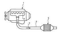
ディーゼルエンジンから排出されるパティキュレート(Particulate Matter:粒子状物質)は、炭素質から成る煤と、高沸点炭化水素成分から成るSOF分(Soluble Organic Fraction:可溶性有機成分)とを主成分とし、更に微量のサルフェート(ミスト状硫酸成分)を含んだ組成を成すものであるが、この種のパティキュレートの低減対策として、図4に示す如く、ディーゼルエンジン1から排気マニホールド2を介して排出された排出ガス3が流通する排気管4の中途部に、酸化触媒を一体的に担持して成る触媒再生型のパティキュレートフィルタ5を装備することが行なわれている。
Particulate matter (particulate matter) discharged from a diesel engine is mainly composed of soot composed of carbonaceous matter and SOF content (Soluble Organic Fraction) composed of high-boiling hydrocarbon components. Although it has a composition containing a small amount of sulfate (mist-like sulfuric acid component), as a measure for reducing this kind of particulates, as shown in FIG. 4, the exhaust discharged from the
このパティキュレートフィルタ5はウォールフローハニカム型で、特許文献1に開示されているものを図5に示すと、セラミックから成る多孔質のハニカム構造となっており、格子状に区画された各流路6の入口は交互にセラミックプラグ7により目封じされ、入口が目封じされていない流路6については、その出口がセラミックプラグ7により目封じされるようになっており、各流路6を区画する多孔質薄壁8を流通した排出ガス3のみが下流側へ排出されるようにしてある。
This
而して、パティキュレートはパティキュレートフィルタ5における多孔質薄壁8の内側表面に捕集され、排気温度の高い運転領域にて自己燃焼して除去されるか、或いは、必要に応じて装備された排気昇温手段による助勢を受けて燃焼除去されることになる。
上記パティキュレートフィルタ5では、多孔質薄壁8におけるパティキュレート捕集性能の向上、及び小型化、すなわち、パティキュレート未捕集時及びパティキュレート捕集時における排出ガス3の多孔質薄壁8に対する通気抵抗(圧力損失)の減少に関し、既に限界近くまで研究がなされ一応の成果のもとに製品化されている。
In the
しかし、ディーゼル車の更なる低公害化のためには、NOx後処理装置も併せて装備する必要があり、一方、車両では後処理装置搭載のためのスペースは限られていることなどから、パティキュレートフィルタ5の一層の小型化の必要性が高まっている。
However, in order to further reduce the pollution of diesel vehicles, it is necessary to equip a NOx aftertreatment device as well. On the other hand, the space for installing the aftertreatment device in a vehicle is limited. The need for further downsizing of the
本発明は、上述の実情に鑑み、ウォールフローハニカム型のパティキュレートフィルタにおいて、パティキュレートの捕集性能を高性能にすること、及び圧力損失の減少特にパティキュレート捕集時の圧力損失の減少を図ることを目的とするものである。 In view of the above-described circumstances, the present invention provides a high performance particulate trapping performance in a wall flow honeycomb type particulate filter, and a reduction in pressure loss, particularly a pressure loss during particulate collection. The purpose is to plan.
請求項1の発明は、ハニカム構造の多孔質壁により形成されて入口側が目封じされた流路と出口側が目封じされた流路とを備え、入口側が目封じされていない流路から流入して多孔質壁を流通した排出ガスは、出口側が目封じされていない流路を経て排出されるようにした排ガス浄化フィルタにおいて、前記多孔質壁を波型又は/及び凹凸形状に形成したものである。
The invention of
請求項2の排ガス浄化フィルタの多孔質壁は、コージライト製であり、請求項3の排ガス浄化フィルタの多孔質壁は、SiC製であり、請求項4の排ガス浄化フィルタの多孔質壁はチタン酸アルミ製であり、請求項5の排ガス浄化フィルタにおいては、排出ガスは内燃機関からの排出ガスである。
The porous wall of the exhaust gas purification filter of claim 2 is made of cordierite, the porous wall of the exhaust gas purification filter of
本発明の請求項1〜5記載の排ガス浄化フィルタによれば、下記のごとき種々の優れた効果を奏し得る。
I)多孔質壁を波型とすることにより、排ガス浄化フィルタの体積を大きくすることなく、濾過面積を増加することができ、多孔質壁の単位面積当たりのガス流量を減少させることができる。
II)パティキュレートの捕集量が、波型を設けない多孔質壁と同一の場合、波型を設けた多孔質壁では、捕集されたパティキュレートの堆積層の厚さを薄くすることができるため、圧力損失の低減が可能となる。
III)多孔質壁の単位面積に対するガス流量の減少により、ガス流速も低下するため、この点からもパティキュレートの捕集性能が向上すると共に、圧力損失も減少する。
IV)多孔質壁に波型を設けてあるため、熱応力を緩和することができ、その結果、多孔質壁に亀裂が発生することを有効に防止することができ、排ガス浄化フィルタの耐久信頼性が向上する。
According to the exhaust gas purification filter of the first to fifth aspects of the present invention, various excellent effects as described below can be obtained.
I) By making the porous wall corrugated, the filtration area can be increased without increasing the volume of the exhaust gas purification filter, and the gas flow rate per unit area of the porous wall can be reduced.
II) When the collected amount of the particulates is the same as that of the porous wall not provided with the corrugated shape, the thickness of the deposited layer of the collected particulates may be reduced in the porous wall provided with the corrugated shape. Therefore, the pressure loss can be reduced.
III) Since the gas flow rate is reduced due to the reduction of the gas flow rate relative to the unit area of the porous wall, the particulate collection performance is improved and the pressure loss is also reduced from this point.
IV) Since the corrugated shape is provided in the porous wall, it is possible to relieve the thermal stress, and as a result, it is possible to effectively prevent the porous wall from cracking, and the exhaust gas purification filter has a durable reliability. Improves.
以下、本発明の実施の形態を添付図面を参照して説明する。
図1〜図3は本発明を実施する形態の一例であり、図中、図4、図5と同一の符号を付した部分は同一物を表わし、基本的な構成は図5に示す従来のものと略同様である。
Embodiments of the present invention will be described below with reference to the accompanying drawings.
1 to 3 show an example of an embodiment of the present invention. In the figure, the same reference numerals as those in FIGS. 4 and 5 denote the same components, and the basic configuration is the conventional configuration shown in FIG. It is almost the same as that.
而して、本図示例の特徴とするところは、図3に拡大して示すように、多孔質薄壁8を波型とした点である。波型は図示例ではパティキュレートフィルタ5の径方向に形成してあるが、軸心方向に形成しても良い。
Thus, the feature of the illustrated example is that the porous
本図示例においては、ディーゼルエンジン1から排出された排出ガス3中のパティキュレートのパティキュレートフィルタ5における捕集、燃焼除去は図4、図5に示す従来の場合と同様に行なわれる。而して、本図示例のように、多孔質薄壁8を波型とすることにより、パティキュレートフィルタ5の体積を大きくすることなく、濾過面積を増加することができ、多孔質薄壁8の単位面積当たりのガス流量を減少させることができる。
In the illustrated example, particulates in the
又、パティキュレートフィルタ5におけるパティキュレートの捕集量が、多孔質薄壁8に波型を設ける場合と設けない場合で同一とすると、波型を設けた多孔質薄壁8では、捕集されたパティキュレートの堆積層の厚さを薄くすることができるため、圧力損失の低減が可能となり、更に、多孔質薄壁8の単位面積に対するガス流量の減少により、ガス流速も低下するため、この点からもパティキュレートの捕集性能が向上すると共に、圧力損失も減少する。
Further, if the amount of particulates collected by the
更に又、多孔質薄壁8に波型がない場合には、多量のパティキュレートが内部で局所的に急激な燃焼を行なうと、多孔質薄壁8に大きな熱応力が発生して当該多孔質薄壁8に亀裂が生じる虞があるが、本図示例のように、多孔質薄壁8に波型を設けると、多孔質薄壁8の波型方向への延び代が大きいため、波型方向への熱応力を緩和することができ、その結果、多孔質薄壁8に亀裂が発生することを有効に防止することができる。従って、パティキュレートフィルタ5の耐久信頼性が向上する。
Furthermore, when the porous
本図示例のパティキュレートフィルタ5は以下の場合に適用する。
I)コージライト製の一体型パティキュレートフィルタに適用する。製作は押し出し成形により行なう。波型の形状、ピッチは成形時の金型の形状、圧力、バインダの種類の調整により行なうことができる。コストの上昇は少ない。
II)SiC製の分割型パティキュレートフィルタに適用する。製作はI)の場合と同様にして行なうことができる。コストの上昇も少ない。
III)チタン酸アルミ製の一体型パティキュレートフィルタに適用する。製作はI)の場合と同様にして行なうことができる。波型の形状、ピッチは成形時の金型の形状、圧力、バインダの種類の調整により行なうことができる。コストの上昇も少ない。
The
I) Applicable to cordierite integrated particulate filter. Manufacture is performed by extrusion. The wave shape and pitch can be adjusted by adjusting the shape, pressure and binder type of the mold during molding. There is little increase in cost.
II) Applicable to a segmented particulate filter made of SiC. Manufacture can be performed in the same manner as in I). There is little increase in cost.
III) Applicable to an integral particulate filter made of aluminum titanate. Manufacture can be performed in the same manner as in I). The wave shape and pitch can be adjusted by adjusting the shape, pressure and binder type of the mold during molding. There is little increase in cost.
なお、本発明の排ガス浄化フィルタにおいては、多孔質薄壁を波型にする場合について説明したが、波型に限らず凹凸形状ならどのような形状にしても実施できること、波型と他の凹凸形状を組合せても実施可能なこと、その他、本発明の要旨を逸脱しない範囲内において種々変更を加え得ることは勿論である。 In the exhaust gas purification filter of the present invention, the case where the porous thin wall is corrugated has been described. However, the present invention is not limited to the corrugated shape, and can be implemented in any shape as long as it is concave and convex. Needless to say, the present invention can be implemented by combining shapes, and various modifications can be made without departing from the scope of the present invention.
1 ディーゼルエンジン(内燃機関)
3 排出ガス
5 パティキュレートフィルタ(排ガス浄化フィルタ)
6 流路
8 多孔質薄壁(多孔質壁)
1 Diesel engine (internal combustion engine)
3
6
Claims (5)
Priority Applications (1)
| Application Number | Priority Date | Filing Date | Title |
|---|---|---|---|
| JP2005155369A JP2006329108A (en) | 2005-05-27 | 2005-05-27 | Exhaust gas purification filter |
Applications Claiming Priority (1)
| Application Number | Priority Date | Filing Date | Title |
|---|---|---|---|
| JP2005155369A JP2006329108A (en) | 2005-05-27 | 2005-05-27 | Exhaust gas purification filter |
Publications (1)
| Publication Number | Publication Date |
|---|---|
| JP2006329108A true JP2006329108A (en) | 2006-12-07 |
Family
ID=37551047
Family Applications (1)
| Application Number | Title | Priority Date | Filing Date |
|---|---|---|---|
| JP2005155369A Pending JP2006329108A (en) | 2005-05-27 | 2005-05-27 | Exhaust gas purification filter |
Country Status (1)
| Country | Link |
|---|---|
| JP (1) | JP2006329108A (en) |
Cited By (5)
| Publication number | Priority date | Publication date | Assignee | Title |
|---|---|---|---|---|
| JP2010517743A (en) * | 2007-02-05 | 2010-05-27 | サン−ゴバン サントル ドゥ ルシェルシェ エ デトゥードゥ ユーロペン | Gas filtration structure with corrugated walls |
| JP2011523585A (en) * | 2008-05-09 | 2011-08-18 | エミテック ゲゼルシヤフト フユア エミツシオンス テクノロギー ミツト ベシユレンクテル ハフツング | Particle filter with hydrolytic coating |
| JP2012115745A (en) * | 2010-11-30 | 2012-06-21 | Ngk Insulators Ltd | Honeycomb structure |
| JP2012115744A (en) * | 2010-11-30 | 2012-06-21 | Ngk Insulators Ltd | Honeycomb structure |
| WO2017141609A1 (en) * | 2016-02-15 | 2017-08-24 | 株式会社村田製作所 | Filtration filter and filtration filter device |
-
2005
- 2005-05-27 JP JP2005155369A patent/JP2006329108A/en active Pending
Cited By (6)
| Publication number | Priority date | Publication date | Assignee | Title |
|---|---|---|---|---|
| JP2010517743A (en) * | 2007-02-05 | 2010-05-27 | サン−ゴバン サントル ドゥ ルシェルシェ エ デトゥードゥ ユーロペン | Gas filtration structure with corrugated walls |
| JP2011523585A (en) * | 2008-05-09 | 2011-08-18 | エミテック ゲゼルシヤフト フユア エミツシオンス テクノロギー ミツト ベシユレンクテル ハフツング | Particle filter with hydrolytic coating |
| JP2012115745A (en) * | 2010-11-30 | 2012-06-21 | Ngk Insulators Ltd | Honeycomb structure |
| JP2012115744A (en) * | 2010-11-30 | 2012-06-21 | Ngk Insulators Ltd | Honeycomb structure |
| WO2017141609A1 (en) * | 2016-02-15 | 2017-08-24 | 株式会社村田製作所 | Filtration filter and filtration filter device |
| US11052337B2 (en) | 2016-02-15 | 2021-07-06 | Murata Manufacturing Co., Ltd. | Filtration filter and filtration filter device |
Similar Documents
| Publication | Publication Date | Title |
|---|---|---|
| JP6140509B2 (en) | Wall flow type exhaust gas purification filter | |
| CN101801499B (en) | Tuning particulate filter performance through selective plugging and use of multiple particulate filters to reduce emissions and improve thermal robustness | |
| CN102625727B (en) | Particulate filters and methods of filtering particulate matter | |
| EP1371826A3 (en) | Filter catalyst for purifying exhaust gases | |
| CN1272089C (en) | Exhaust gas system | |
| CN1271318C (en) | Filtering body for filtering particles contained in internal combustion engine exhaust gases | |
| CN105899773B (en) | Modular system for a catalyst assembly and method for manufacturing a catalyst assembly | |
| US20180149066A1 (en) | Exhaust pipe structure for internal combustion engine | |
| CN106499478B (en) | Exhaust gas treatment device, method for raising temperature of catalyst, method for regenerating honeycomb structure, and method for removing ash | |
| JP2006329108A (en) | Exhaust gas purification filter | |
| CN209761531U (en) | Exhaust pipe assembly and automobile | |
| KR101261949B1 (en) | catalyst unit | |
| JP2006077591A (en) | Exhaust purification device | |
| JP2009007982A (en) | Exhaust gas purification device for internal combustion engine | |
| JP2006161629A (en) | Exhaust purification device | |
| KR20040105279A (en) | Diesel Particulate Filter for automobile | |
| JP6168304B2 (en) | Engine exhaust gas purification device | |
| JP2009115022A (en) | Exhaust purification device | |
| KR101745169B1 (en) | Muffler integrated type gasoline particulate filter | |
| CN214660441U (en) | Automobile purification silencer | |
| JP2009062875A (en) | Exhaust purification device | |
| KR100587136B1 (en) | Filter catalyst structure for diesel engine | |
| JP2005291062A (en) | Filter device, and exhaust emission control device provided with the same | |
| KR100636051B1 (en) | Particulate matter filter structure for diesel engine | |
| US20100139261A1 (en) | Exhaust Gas Filter System |