JP2006279555A - Signal regeneration apparatus and method - Google Patents
Signal regeneration apparatus and method Download PDFInfo
- Publication number
- JP2006279555A JP2006279555A JP2005095713A JP2005095713A JP2006279555A JP 2006279555 A JP2006279555 A JP 2006279555A JP 2005095713 A JP2005095713 A JP 2005095713A JP 2005095713 A JP2005095713 A JP 2005095713A JP 2006279555 A JP2006279555 A JP 2006279555A
- Authority
- JP
- Japan
- Prior art keywords
- sound source
- signal
- sound
- information
- sound image
- Prior art date
- Legal status (The legal status is an assumption and is not a legal conclusion. Google has not performed a legal analysis and makes no representation as to the accuracy of the status listed.)
- Pending
Links
- 238000000034 method Methods 0.000 title claims abstract description 29
- 230000008929 regeneration Effects 0.000 title abstract 4
- 238000011069 regeneration method Methods 0.000 title abstract 4
- 238000004364 calculation method Methods 0.000 claims abstract description 63
- 230000005236 sound signal Effects 0.000 claims description 61
- 230000015572 biosynthetic process Effects 0.000 claims description 30
- 238000004458 analytical method Methods 0.000 claims description 23
- 238000000605 extraction Methods 0.000 abstract description 35
- 230000008447 perception Effects 0.000 abstract description 6
- 238000012545 processing Methods 0.000 description 147
- 230000003287 optical effect Effects 0.000 description 24
- 230000008859 change Effects 0.000 description 11
- 239000000284 extract Substances 0.000 description 10
- 238000003786 synthesis reaction Methods 0.000 description 10
- 230000001755 vocal effect Effects 0.000 description 10
- 230000000875 corresponding effect Effects 0.000 description 9
- 238000010586 diagram Methods 0.000 description 9
- 238000000926 separation method Methods 0.000 description 9
- 230000003321 amplification Effects 0.000 description 7
- 230000004807 localization Effects 0.000 description 7
- 238000003199 nucleic acid amplification method Methods 0.000 description 7
- 230000002194 synthesizing effect Effects 0.000 description 7
- 230000001172 regenerating effect Effects 0.000 description 4
- 230000006870 function Effects 0.000 description 3
- 239000000203 mixture Substances 0.000 description 3
- ZYXYTGQFPZEUFX-UHFFFAOYSA-N benzpyrimoxan Chemical compound O1C(OCCC1)C=1C(=NC=NC=1)OCC1=CC=C(C=C1)C(F)(F)F ZYXYTGQFPZEUFX-UHFFFAOYSA-N 0.000 description 2
- 230000005540 biological transmission Effects 0.000 description 2
- 238000004891 communication Methods 0.000 description 2
- 230000000694 effects Effects 0.000 description 2
- 238000005516 engineering process Methods 0.000 description 2
- 230000007480 spreading Effects 0.000 description 2
- 230000001360 synchronised effect Effects 0.000 description 2
- 101000969688 Homo sapiens Macrophage-expressed gene 1 protein Proteins 0.000 description 1
- 102100021285 Macrophage-expressed gene 1 protein Human genes 0.000 description 1
- JDZPLYBLBIKFHJ-UHFFFAOYSA-N Sulfamoyldapsone Chemical compound C1=CC(N)=CC=C1S(=O)(=O)C1=CC=C(N)C=C1S(N)(=O)=O JDZPLYBLBIKFHJ-UHFFFAOYSA-N 0.000 description 1
- 230000002596 correlated effect Effects 0.000 description 1
- 230000007423 decrease Effects 0.000 description 1
- 238000001514 detection method Methods 0.000 description 1
- 238000011161 development Methods 0.000 description 1
- 238000012544 monitoring process Methods 0.000 description 1
- 238000004806 packaging method and process Methods 0.000 description 1
- 230000008569 process Effects 0.000 description 1
- 230000008707 rearrangement Effects 0.000 description 1
- 238000004350 spin decoupling difference spectroscopy Methods 0.000 description 1
- 230000002123 temporal effect Effects 0.000 description 1
Images


Landscapes
- Signal Processing For Digital Recording And Reproducing (AREA)
- Stereophonic System (AREA)
Abstract
Description
本発明は、信号再生装置及び信号再生方法に関し、特にマルチチャンネル方式と音場合成技術により音像を仮想音源位置に定位させる信号再生装置及び信号再生方法に関する。 The present invention relates to a signal reproduction device and a signal reproduction method, and more particularly to a signal reproduction device and a signal reproduction method for localizing a sound image to a virtual sound source position by a multi-channel method and a sound field synthesis technique.
大容量記憶媒体、ネットワークを介したダウンロード又はストリームによるコンテンツ配信等をはじめとする情報伝達形態の発達と再生機器性能の進化により、家庭でも高画質、高音質で映像コンテンツ及び音楽コンテンツが楽しめるようになった。 With the development of information transmission forms such as large-capacity storage media, content distribution by download or stream over the network, and the evolution of playback device performance, video content and music content can be enjoyed at home with high image quality and high sound quality. became.
ビデオデータ、音楽データ等の再生装置において臨場感や音質は、ユーザにとって善し悪しが比較的判断しやすい。例えば、ユーザがオーケストラ曲を聴くとき、仮想音場のなかで個々の楽器の位置が鮮明に感じられ、本物のオーケストラが眼前で演奏しているかのようなイメージが想起されることが好ましい。ユーザは、より現実味のある音声再生を望む傾向にあり、音を再生したときに音声或いは音楽を録音したときの音場が如何に忠実に再現できているかがユーザに機器特性の印象を与えてしまうことにもなるため、重要になっている。 In a playback device for video data, music data, etc., the sense of reality and sound quality are relatively easy for the user to judge. For example, when a user listens to orchestra music, it is preferable that the position of each instrument is clearly felt in the virtual sound field, and an image as if a real orchestra is playing in front of the eyes is recalled. Users tend to desire more realistic sound reproduction, and how the sound field when sound or music is recorded can be reproduced faithfully when the sound is reproduced. It becomes important because it will end up.
例えば、2チャンネルステレオでは、再生音場の音像が虚音像として最適な場所に定位するようにL信号とR信号からなる2チャンネルステレオ信号の各信号チャンネルのバランスを調整し2つのスピーカから出力している。しかし、2チャンネルステレオの場合、虚音像は、音像が鮮明でなく、受聴位置が左右スピーカの中央からずれると音像の定位位置が変化してしまうという欠点があった。そこで、少なくとも左右に設置した2つのスピーカの中央位置、すなわち受聴者の正面位置にはより鮮明な音像が定位し且つ受聴位置が左右にずれても音像が中央に留まっているようにするために、左右の2チャンネルスピーカの中央にセンタスピーカを加えた3チャンネルステレオ方式、更に背面スピーカを加えた5.1チャンネルステレオ方式が存在する。 For example, in 2-channel stereo, the balance of each signal channel of 2-channel stereo signal consisting of L signal and R signal is adjusted and output from two speakers so that the sound image of the reproduction sound field is localized at the optimum place as a virtual sound image. ing. However, in the case of 2-channel stereo, the virtual image has a drawback that the sound image is not clear and the localization position of the sound image changes when the listening position deviates from the center of the left and right speakers. Therefore, in order to ensure that a clearer sound image is localized at the center position of at least two speakers installed on the left and right sides, that is, the front position of the listener, and the sound image remains in the center even if the listening position is shifted left and right. There are a three-channel stereo system in which a center speaker is added to the center of left and right two-channel speakers, and a 5.1-channel stereo system in which a rear speaker is further added.
一方、従来一般的な2チャンネルステレオ信号は、3チャンネル、5.1チャンネルのような多チャンネルステレオ装置によっても再生できなければならない。そのために、2チャンネルステレオ信号からセンターチャンネルの信号や背面のLチャンネルと背面のRチャンネルの信号を生成することによって、2チャンネルステレオ信号を多チャンネル信号に変換できるようにした技術も公開されている(特許文献1参照)。 On the other hand, a conventional two-channel stereo signal must be able to be reproduced by a multi-channel stereo device such as a three-channel or 5.1-channel device. For this purpose, a technique has been disclosed that can convert a 2-channel stereo signal into a multi-channel signal by generating a center channel signal or a rear L channel signal and a rear R channel signal from a two-channel stereo signal. (See Patent Document 1).
また、より現実味のある音場を再現するための技術としては、このほかにも、音場合成技術を用いて点音源や平面波を合成することにより5.1チャンネルステレオ信号を再生する技術(非特許文献1参照)、音場合成技術の仮想音源の位置制御技術を利用して音像位置を任意に動かす技術が開示されている(非特許文献2参照)。更に、混合された音響信号から特定の信号を抽出する一般調和信号解析技術があげられる(非特許文献3参照)。 In addition to this, as a technique for reproducing a more realistic sound field, a technique for reproducing a 5.1 channel stereo signal by synthesizing a point sound source or a plane wave using a sound case forming technique (non-synthesizing) Patent Document 1), and a technique for arbitrarily moving a sound image position by using a virtual sound source position control technique of sound case formation technology is disclosed (see Non-Patent Document 2). Furthermore, there is a general harmonic signal analysis technique for extracting a specific signal from a mixed acoustic signal (see Non-Patent Document 3).
ところが、2チャンネルステレオ信号からセンターチャンネルの信号を合成する方法は、簡便ではあるが鮮明な音像を得られない。また、非特許文献3に説明されている一般調和信号解析技術により、従来の2チャンネルステレオ信号に含まれる音源の信号を抽出し、音源毎に独立した信号のチャンネルを作り出すには多くの信号処理が必要である。また生成されたチャンネルの信号処理の結果を検証し、処理条件を変えて再度信号処理をやり直すという繰り返し処理が必要になることもあるため、2チャンネルステレオ信号に対してリアルタイムで一般調和信号解析処理を実行し、検出結果を再合成して多チャンネルステレオ信号を生成しこれをリアルタイム再生することは困難であった。 However, although the method of synthesizing the center channel signal from the two-channel stereo signal is simple, a clear sound image cannot be obtained. In addition, the general harmonic signal analysis technique described in Non-Patent Document 3 extracts a sound source signal included in a conventional two-channel stereo signal, and produces many independent signal channels for each sound source. is required. In addition, it may be necessary to repeat the process of verifying the signal processing results of the generated channel and changing the processing conditions again, so that the general harmonic signal analysis processing is performed in real time on the 2-channel stereo signal. It was difficult to re-synthesize the detection results to generate a multi-channel stereo signal and reproduce it in real time.
そこで、本発明は、上述した従来の実情に鑑みて提案されたものであり、再現音場内の最適位置に鮮明な虚音像を定位することができる信号再生装置及びその方法を提供することを目的とする。 Therefore, the present invention has been proposed in view of the above-described conventional situation, and an object of the present invention is to provide a signal reproducing apparatus and method capable of localizing a clear virtual sound image at an optimal position in a reproduced sound field. And
上述した目的を達成するために、本発明に係る信号再生装置は、オーディオ信号が多重化された多チャンネルデータを再生する信号再生装置において、多チャンネルデータを取得する多チャンネルデータ取得手段と、多チャンネルデータから特定音像の音源情報と音像位置情報とを抽出する信号解析手段と、音源情報から音源信号を算出する音源信号算出手段と、抽出された特定音像の音像情報を変更し変更後の特定音像の音源信号を任意の仮想音源位置に配置する音場合成を行う音場合成手段とを備え、再現音場内の最適位置に鮮明な虚音像を定位する。 In order to achieve the above-described object, a signal reproduction apparatus according to the present invention includes a multi-channel data acquisition unit that acquires multi-channel data in a signal reproduction apparatus that reproduces multi-channel data in which audio signals are multiplexed, Signal analysis means for extracting sound source information and sound image position information of a specific sound image from channel data, sound source signal calculation means for calculating a sound source signal from sound source information, and specifying after changing the sound image information of the extracted specific sound image Sound field generating means for performing sound field generation in which a sound source signal of a sound image is arranged at an arbitrary virtual sound source position is provided, and a clear virtual sound image is localized at an optimum position in the reproduced sound field.
ここで、本発明に係る信号再生装置は、抽出された特定音像の音源情報と音像位置情報とにしたがって特定音像の仮想音源位置を算出する仮想音源位置算出手段を備え、この場合、音場合成手段は、音源信号算出手段において算出された音源信号を仮想音源算出手段で算出された仮想音源位置に配置する。 Here, the signal reproduction device according to the present invention includes virtual sound source position calculating means for calculating the virtual sound source position of the specific sound image according to the extracted sound source information and sound image position information of the specific sound image. The means places the sound source signal calculated by the sound source signal calculating means at the virtual sound source position calculated by the virtual sound source calculating means.
また、上述した目的を達成するために、本発明に係る信号再生方法は、オーディオ信号が多重化された多チャンネルデータを再生する信号再生方法において、多チャンネルデータを取得する多チャンネルデータ取得工程と、多チャンネルデータから特定音像の音源情報と音像位置情報を抽出する信号解析工程と、音源情報から音源信号を算出する音源信号算出工程と、抽出された特定音像の音像情報を変更し変更後の特定音像の音源信号を任意の仮想音源位置に配置する音場合成を行う音場合成工程とを有する。 In order to achieve the above-described object, a signal reproduction method according to the present invention includes a multichannel data acquisition step of acquiring multichannel data in a signal reproduction method of reproducing multichannel data in which audio signals are multiplexed. , A signal analysis step of extracting sound source information and sound image position information of a specific sound image from multi-channel data, a sound source signal calculation step of calculating a sound source signal from the sound source information, and changing the sound image information of the extracted specific sound image A sound case generation step for performing sound case formation in which a sound source signal of a specific sound image is arranged at an arbitrary virtual sound source position.
本発明に係る信号再生装置及び信号再生方法によれば、再現音場内の最適位置に鮮明な虚音像を定位させた音場合成が可能になる。また、オーディオ信号が多重化された多チャンネルデータから特定音像の音源情報及び音像位置情報を分離して用意することで、音場解析と音場合成処理に係る処理負荷が軽減できる。 According to the signal reproducing device and the signal reproducing method of the present invention, it is possible to generate a sound when a clear virtual sound image is localized at an optimum position in the reproduced sound field. Also, by separating and preparing sound source information and sound image position information of a specific sound image from multi-channel data in which audio signals are multiplexed, the processing load related to sound field analysis and sound case formation processing can be reduced.
本発明の具体例として示す信号再生装置は、マルチチャンネル方式で作成され、複数の音源情報を含む音楽データに対して、一般調和信号解析技術をはじめとする音源信号抽出と音場合成技術とを用いて、オーディオ信号から特定の音源信号を抽出し、この音源信号の音像を最適な仮想音源位置に定位させる信号処理を行う再生装置である。 A signal reproducing apparatus shown as a specific example of the present invention is a multi-channel method, and for music data including a plurality of sound source information, a sound source signal extraction including a general harmonic signal analysis technique and a sound case forming technique are performed. It is a playback device that performs signal processing to extract a specific sound source signal from an audio signal and localize the sound image of this sound source signal to an optimal virtual sound source position.
なお、本発明では、オーディオ信号が多重化されたデータとは、例えば、複数の楽器で演奏された音楽データ、“演奏”と“歌声”とが含まれる音楽データのように複数の音源が含まれるオーディオデータであって、リニアPCM(Linear Pulse Code Modulation)、ドルビーデジタル、DTS(Digital Theater Systems)、DVD−Audioフォーマット、DVD−Videoフォーマットに決められたオーディオデータを含むが、いわゆるMIDI(Musical Instrument Digital Interface)規格に準拠するデータのように、予めチャンネル毎(音源毎)に作成された複数パートのデータを合成(多重化)してできるオーディオデータは、本発明及び本発明の具体例では含まれない。 In the present invention, the data in which the audio signal is multiplexed includes, for example, a plurality of sound sources such as music data played by a plurality of musical instruments and music data including “performance” and “singing voice”. Audio data including audio data determined in linear PCM (Linear Pulse Code Modulation), Dolby Digital, DTS (Digital Theater Systems), DVD-Audio format, and DVD-Video format. Audio data that can be synthesized (multiplexed) with multiple parts of data created in advance for each channel (for each sound source), such as data that conforms to the Digital Interface) standard, is included in the present invention and specific examples of the present invention. I can't.
以下、本発明の第1の具体例として示す信号再生装置1について、図面を参照して詳細に説明する。信号再生装置1は、記録媒体から入力したオーディオデータを含むコンテンツデータを再生する再生装置である。
Hereinafter, a
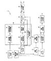
図1に示す信号再生装置1は、光ディスクを回転駆動し記録されたデータを読み出す光ディスク再生部11と、読み出したデータを圧縮されたオーディオデータ、ビデオデータ、字幕データ、その他のデータ等に分離する信号分離回路12とを備える。また、圧縮されたオーディオデータを復号するオーディオデコーダ13と、復号されたオーディオデータを再生するとともに仮想音源の位置情報に応じて音場合成するオーディオ信号処理回路14と、圧縮された字幕データを復号する字幕デコーダ15と、復号された字幕を再生する字幕再生回路16とを備えている。また、圧縮されたビデオデータを復号するビデオデコーダ17と、復号されたビデオデータを再生するビデオ信号再生回路18と、ビデオ信号に同期して字幕を合成する字幕合成回路19と、字幕が合成されたビデオ信号を外部に出力するビデオ信号出力回路20とを備える。
A
なお、オーディオデコーダ13からの出力とこれに対応する音源信号算出処理部26及びオーディオ信号再生処理部23への入力、並びに音が合成処理部27からの出力とこれに対応する多チャンネルアンプ21への入力、オーディオ信号出力回路22への入力及び出力は、チャンネル数に併せた信号線が用意されている。
The output from the
オーディオデータ及びビデオデータとしては、MPEG1、MPEG2、AVI、WMV、WMA等の各フォーマットが適用可能であるが、以下に説明する例では、光ディスクとしてDVD(Digital Versatile Disc)を使用する。この場合、ビデオデータはMPEG(Moving Picture Experts Group)によって標準化されたMPEG2であり、オーディオデータは、リニアPCM、ドルビーデジタル、DTS、SDDS等が適用される。 As audio data and video data, formats such as MPEG1, MPEG2, AVI, WMV, and WMA are applicable. In the example described below, a DVD (Digital Versatile Disc) is used as an optical disk. In this case, video data is MPEG2 standardized by the Moving Picture Experts Group (MPEG), and linear PCM, Dolby Digital, DTS, SDDS, etc. are applied as audio data.
オーディオ信号処理回路14は、オーディオデコーダ13で復号されたオーディオデータを再生するオーディオ信号再生処理部23と、光ディスク再生部11で再生された再生信号から音像情報を抽出する処理を行う音像情報抽出処理部24と、仮想音源位置を算出する仮想音源位置算出処理部25と、音像情報から音源信号を算出する音源信号算出処理部26と、音源信号と仮想音源位置に基づいて音場を合成する音場合成処理部27とを備える。
The audio
オーディオ信号再生処理部23は、オーディオデコーダ13で復号されたオーディオデータを再生し多チャンネルアンプ21に送る。
The audio signal
音像情報抽出処理部24は、光ディスク再生部11が読み出したデータから音像情報と音像位置情報とを抽出し、抽出した音像情報及び音像位置情報を仮想音源位置算出処理部25と音源信号算出処理部26に送る。音源情報としては、オーディオデータを構成する楽器、音声等があげられる。また、音像情報抽出処理部24は、一般調和信号解析により数種類の音源からの音が混在した音声波形から主要音源の時間変動に相関がある周波数成分を抽出する。例えば、音像情報抽出処理部24は、一般調和信号解析によって、目的の女声ボーカル信号を構成する周波数成分を分離することができる。また、例えば中央位置に定位させる音源信号の周波数成分を分離することができる。
The sound image information
仮想音源位置算出処理部25は、音像情報抽出処理部24で抽出された音像位置情報にしたがって音場を合成すべき音源位置を算出する。ここで、音場合成すべき音源位置とは、後段の音場合成処理部27の精度やスピーカ配置に応じた仮想音源の位置である。仮想音源位置算出処理部25は、例えば中央位置に音像定位する音源信号であれば、聴取点からこの音仮想源信号までの仮想音源距離を、後段の音場合成処理部27の精度やスピーカ配置に応じて計算して算出又は変更する。
The virtual sound source position
音源信号算出処理部26は、音像情報抽出処理部24で一般調和信号解析によって音源毎に分離されたオーディオデータに仮想音源位置算出処理部25で算出した音源位置に所定の音源を音像定位させるための制御パラメータを与える。図2〜図5には、オーディオデータから分離された周波数波形を示す。
The sound source signal
音源信号算出処理部26は、2チャンネルオーディオデータ、多チャンネルオーディオデータ等のオーディオデータから音像情報抽出処理部24及び仮想音源位置算出処理部25における解析結果に基づいて特定位置に音像定位する音源信号、パート毎に異なる音源信号を分離している。例えば、音源信号算出処理部26は、音像情報抽出処理部24で一般調和信号解析によって分離された目的の女声ボーカル信号を構成する周波数成分から女声ボーカルの音源信号を算出する。また、例えば中央位置に定位させる音源信号の周波数成分を分離することができる。音源信号算出処理部26は、算出した音源信号を音場合成処理部27に送る。
The sound source signal
また、音源信号算出処理部26は、分離した所定の周波数成分を広がり方向(水平方向)、又は奥行き方向に定位位置変更する制御パラメータを算出する。
The sound source signal
音源音像を広がり方向(水平方向)に定位位置変更するための制御パラメータの変更例として、音源信号算出処理部26は、例えば、観測点と仮想音源との方向に関して、後述する音場合成処理部27の精度が10°刻み程度の精度でしか音場合成できない場合には、音像方向8°刻みの音像位置変化を生じさせるパラメータを10°に再変換する。また、スピーカ配置上の制約で横方向に40°の範囲内にしか音像配置できない場合には、音像位置50°という音像位置変化を生じさせるパラメータは40°に再変換する。
As an example of changing the control parameter for changing the localization position of the sound source sound image in the spreading direction (horizontal direction), the sound source signal
また、観測点と仮想音源との距離である音像位置距離データについても同様である。一般的に、3メートル以上の遠方の音源に対しては人間の距離知覚の精度が低下することが知られている。そこで音源信号算出処理部26は、音源音像を奥行き方向に定位位置変更するための制御パラメータの変更例として、例えば、音像距離5メートル程度の距離変化を生じさせるパラメータを音源位置3メートル程度に音像定位させるパラメータに変換し、音像距離8メートル程度の距離変化を生じさせるパラメータを音源距離10メートルに再変換する。
The same applies to the sound image position distance data, which is the distance between the observation point and the virtual sound source. In general, it is known that the accuracy of human distance perception decreases for a sound source farther than 3 meters. Therefore, the sound source signal
また、音源信号算出処理部26は、分離された音源に基づいて新たな音源信号を作成することもできる。例えば、音像情報抽出処理部24によって分離された特定音源の音源信号を別の位置に定位させるパラメータを算出したり、特定音源と周波数が若干異なる音源信号を生じるための制御パラメータを算出したりする。これにより、ある音源に対していわゆるユニゾンする別の音源、或いはある音源とハーモニーを生じる別の音源の周波数成分を生成することができる。
The sound source signal
音場合成処理部27は、音源信号算出処理部26によって算出された音源信号を仮想音源位置算出処理部25で算出された仮想音源位置に配置する音場合成を行う。このとき、音場合成処理部27は、ピッチ変更、タイミング変更、エンベロープジェネレータのうち1又は組合せにより、抽出された音源信号を仮想音源位置に再配置する音場合成を行う。また、音場合成処理部27は、中央位置に音像定位する音源信号が取り除かれたインテンシティステレオ信号を通常のインテンシティステレオ再生し、分離した音源信号を中央位置に再配置する音場合成を行う。
The sound case
オーディオ信号出力回路22にオーディオ信号の出力手段の一例として平面アレイスピーカが使用される場合、音場合成処理部27は、中央位置から同心円状に広がる音波を出力するためのアレイスピーカ駆動用のデジタルフィルタ係数を算出し、目的のボーカル信号に畳み込み演算を行う。
When a planar array speaker is used as an example of an audio signal output means for the audio
図2〜図5は、音像情報抽出処理部24によって分離された周波数成分を示している。図2〜図5において横軸は時間であり、縦軸は信号レベルを表している。図2に示す周波数成分f1の信号レベルと図3に示す周波数成分f2の信号レベルは、互いに時間変動に強い相関があるため、音場合成処理部27は、f1とf2を同じ音源として音像定位する。また、音場合成処理部27は、同様に、図4に示す周波数成分f3と図5に示す周波数成分f4とを同じ音源として音像定位する。
2 to 5 show frequency components separated by the sound image information
音源信号算出処理部26は、元のオーディオ信号から一般調和信号解析によって分離された図2〜図5に示す周波数成分f1〜f4に対して、互いに時間変動に強い相関があるものを同じ音源とし、再生空間内における同一位置に定位させるための制御パラメータを与える。音場合成処理部27は、与えられた制御パラメータを抽出した周波数成分に、例えばf1とf2に重畳して再合成する。そして、この抽出した音源の周波数成分に所定の音源に、同じ音源として音像定位させるためのパラメータが与えられ、所定の楽器の周波数成分として再合成する。
The sound source signal
続く多チャンネルアンプ21は、アレイスピーカ用の多チャンネル信号を増幅するとともに、オーディオ信号のうち再合成されなかった音源信号を2チャンネル又は5.1チャンネルで再生するための増幅を行う。例えば、多チャンネルアンプ21は、上述のようにボーカル信号が音場の再合成をするために分離された場合、ボーカル信号をアレイスピーカ用に多チャンネルで増幅し、ボーカル信号成分が分離された後のオーディオ信号をLチャンネル信号、Rチャンネル信号の2チャンネルで増幅する。
The subsequent
上述した構成を有する信号再生装置1が光ディスクから読み出したコンテンツデータを再生する動作について説明する。
An operation of reproducing the content data read from the optical disc by the
光ディスク再生部11は、光ディスクを回転駆動しDVDに記録されたデータを読み出す。光ディスク再生部11によって読み出されたデータは、信号分離回路12において、圧縮されたオーディオデータ、圧縮されたビデオデータ、字幕データ、その他のデータ等に分離される。圧縮されたオーディオデータは、オーディオデコーダ13で復号された後、オーディオ信号処理回路14のオーディオ信号再生処理部23に送られる。オーディオ信号再生処理部23は、復号されたオーディオデータを再生し多チャンネルアンプ21に送る。
The optical disk reproducing unit 11 reads the data recorded on the DVD by rotating the optical disk. The data read by the optical disc reproducing unit 11 is separated into compressed audio data, compressed video data, caption data, other data, and the like by the
光ディスク再生部11によって読み出されたデータは、オーディオ信号処理回路14の音像情報抽出処理部24にも送られる。音像情報抽出処理部24は、一般調和信号解析によって、再生信号から音源毎の音像情報と音像位置情報とを抽出し、抽出した音像情報及び音像位置情報を仮想音源位置算出処理部25と音源信号算出処理部26に送る。仮想音源位置算出処理部25では、音像情報抽出処理部24で抽出された音像位置情報にしたがって音場を合成すべき音源位置が算出される。また、音源信号算出処理部26では、音像情報抽出処理部24で一般調和信号解析によって音源毎に分離されたオーディオデータに仮想音源位置算出処理部25で算出した音源位置に所定の音源を音像定位させるための制御パラメータが与えられる。
The data read by the optical disk reproducing unit 11 is also sent to the sound image information
音場合成処理部27は、音源信号算出処理部26によって算出された音源信号と制御パラメータに基づいて、仮想音源位置算出処理部25で算出された仮想音源位置に配置する音場合成を行う。このとき、音場合成処理部27は、ピッチ変更、タイミング変更、エンベロープジェネレータのうち1又は組合せにより、抽出された音源信号を仮想音源位置に再配置する音場合成を行う。音場合成処理部27において音場が再合成されたオーディオ信号は、多チャンネルアンプ21に送られる。多チャンネルアンプ21では、特定の音声信号、例えばボーカル信号成分が分離された場合、分離されたボーカル信号を多チャンネルで増幅し、ボーカル信号成分が分離された後のオーディオ信号をLチャンネル信号、Rチャンネル信号の2チャンネルで増幅する。
Based on the sound source signal calculated by the sound source signal
一方、ビデオデータと字幕データは、ビデオデコーダ17、字幕デコーダ15に送られ、続く字幕再生回路16或いはビデオ信号再生回路18で再生される。字幕信号とビデオ信号は、字幕合成回路19においてビデオ信号に同期して映像に字幕が合成される。音場が再合成されたオーディオ信号はオーディオ信号出力回路22から、字幕が合成されたビデオ信号はビデオ信号出力回路20から互いに同期され外部のスピーカシステム、表示装置等に出力される。
On the other hand, the video data and the caption data are sent to the
したがって、信号再生装置1は、音像情報抽出処理部24においてオーディオデータに含まれる音源毎の楽音を分離算出し、音源信号算出処理部26において聴取点に近い音源を聴取者の距離知覚が敏感な位置に変更し、遠くに定位される音像をより遠くに再配置するパラメータを算出し、仮想音源位置算出処理部25において算出された仮想音源位置に特定の音源信号を再合成し、再生される仮想音場を再構築することにより、視聴者の臨場感を高めることができる。上述した信号再生装置1は、本発明の基本的な構成を実現したものである。
Therefore, in the
以下では、本発明のほかの応用例について説明する。本発明の第2の具体例として信号再生装置2を図6に示す。図2に示す信号再生装置2は、音像毎の音源情報及び音像位置情報が多チャンネルのオーディオデータから独立して、例えば、楽曲、映画等といったコンテンツ毎にメタデータとして用意されていることが特徴である。そして、このメタデータは、コンテンツと対応づけるためにコンテンツを識別するための識別コードに対応して予め所定の領域に格納されている。ここで識別コードとは、所定のルールを用いてオーディオデータ等のコンテンツデータの一部から生成されたコンテンツ毎に固有な情報である。 In the following, other application examples of the present invention will be described. FIG. 6 shows a signal reproducing device 2 as a second specific example of the present invention. The signal reproduction apparatus 2 shown in FIG. 2 is characterized in that sound source information and sound image position information for each sound image are prepared as metadata for each content such as a song, a movie, etc., independently of multi-channel audio data. It is. This metadata is stored in advance in a predetermined area corresponding to an identification code for identifying the content to be associated with the content. Here, the identification code is information unique to each content generated from a part of content data such as audio data using a predetermined rule.
そのため、信号再生装置2は、オーディオデータから切り離されてコンテンツ毎に所定領域に格納された音源情報及び音像位置情報を読み出すために必要な識別コードを、この識別コードを光ディスクに格納したと同じ手順で生成する識別コード生成部28と、ここで生成された識別コードに対応するメタデータを光ディスクから検索する検索処理部29とを備えることを特徴としている。なお、図6に示す信号再生装置2において、図1に示した信号再生装置1と同様の機能を有する構成は、同一の番号を付けて詳細な説明を省略する。
For this reason, the signal reproduction apparatus 2 uses the same procedure as that for storing the identification code necessary for reading the sound source information and the sound image position information separated from the audio data and stored in a predetermined area for each content on the optical disc. And a
識別コード生成部28は、オーディオデータから切り離されてメタデータとして所定領域に格納された音源情報及び音像位置情報を読み出すために必要な識別コードを、多チャンネルデータの一部から生成する。識別コードとしては、TOCに記録されているトラック数、各トラックの演奏時間等のデータ、またこれらを組み合わせたデータのほか、多チャンネルデータそのものに対して所定の符号化を施して得られるデータ等があげられる。
The identification
検索処理部29は、識別コード生成部28で生成されたコンテンツを特定するための識別コードに応じて演奏対象となっている楽曲の識別コードを多重化されたデータから検索する。
The
上述した構成を有する信号再生装置2が光ディスクから読み出したコンテンツデータを再生する動作について説明する。 An operation of reproducing the content data read from the optical disc by the signal reproducing apparatus 2 having the above-described configuration will be described.
光ディスク再生部11によって読み出されたデータは、信号分離回路12において、圧縮されたオーディオデータ、圧縮されたビデオデータ、字幕データ、その他のデータ等に分離される。圧縮されたオーディオデータは、オーディオデコーダ13で復号された後、オーディオ信号処理回路14のオーディオ信号再生処理部23に送られる。オーディオ信号再生処理部23は、復号されたオーディオデータを再生し多チャンネルアンプ21に送る。
The data read by the optical disc reproducing unit 11 is separated into compressed audio data, compressed video data, caption data, other data, and the like by the
オーディオ信号処理回路14の識別コード生成部28は、光ディスク再生部11で読み出されたデータから作成時と同様のルールで識別コードを生成する。そして、検索処理部29は、生成された識別コードに応じて、演奏対象の楽曲の音源情報及び音像位置情報のデータを多重化されたデータから検索する。
The identification
信号再生装置2では、音像情報抽出処理部24は、検索処理部29が検索して得たメタデータから音源毎の音像情報と音像位置情報とを抽出し、抽出した音像情報及び音像位置情報を仮想音源位置算出処理部25と音源信号算出処理部26に送る。仮想音源位置算出処理部25では、音像情報抽出処理部24で抽出された音像位置情報にしたがって音場を合成すべき音源位置が算出される。また、音源信号算出処理部26では、音像情報抽出処理部24で音源毎に分離されたオーディオデータに仮想音源位置算出処理部25で算出した音源位置に所定の音源を音像定位させるための制御パラメータが与えられる。
In the signal reproduction device 2, the sound image information
音場合成処理部27は、音源信号算出処理部26によって算出された音源信号と制御パラメータに基づいて、仮想音源位置算出処理部25で算出された仮想音源位置に配置する音場合成を行う。このとき、音場合成処理部27は、ピッチ変更、タイミング変更、エンベロープジェネレータのうち1又は組合せにより、抽出された音源信号を仮想音源位置に再配置する音場合成を行う。音場合成処理部27において音場が再合成されたオーディオ信号は、多チャンネルアンプ21に送られ、分離された特定の音源信号を多チャンネルで増幅され、特定の音源信号成分が分離された後のオーディオ信号を2チャンネルで増幅される。字幕信号とビデオ信号は、字幕合成回路19においてビデオ信号に同期して映像に字幕が合成され、音場が再合成されたオーディオ信号はオーディオ信号出力回路22から、また字幕が合成されたビデオ信号はビデオ信号出力回路20から、互いに同期されて外部のスピーカシステム、表示装置等に出力される。
Based on the sound source signal calculated by the sound source signal
上述したように信号再生装置2は、音像毎の音源情報及び音像位置情報を多チャンネルのオーディオデータから独立してメタデータとして用意し、更にメタデータを識別コードに対応して予め所定の領域に格納したことにより、一般調和信号解析等による音源抽出処理にかかる演算量を低減することができる。また、音像情報抽出処理部24において音源毎の信号を分離し、音源信号算出処理部26において聴取点に近い音源を聴取者の距離知覚が敏感な位置に変更し、遠くに定位される音像をより遠くに再配置するパラメータを算出し、仮想音源位置算出処理部25において算出された仮想音源位置に特定の音源信号を再合成し、再生される仮想音場を再構築することにより、視聴者の臨場感を高めることができる。
As described above, the signal reproduction device 2 prepares sound source information and sound image position information for each sound image as metadata independent of multi-channel audio data, and further stores the metadata in a predetermined area corresponding to the identification code. By storing, it is possible to reduce the amount of calculation required for the sound source extraction processing by general harmonic signal analysis or the like. In addition, the sound image information
続いて、本発明の第3の具体例として信号再生装置3を図7に示す。図7では、図1及び図6に示す信号再生装置と同様の機能を有する構成に関しては同一の番号を付けて詳細な説明を省略する。図7に示す信号再生装置3は、上述した多チャンネルのオーディオデータが光ディスクのようないわゆるパッケージングメディアとして提供される場合でなく、ネットワークを介して送られる場合である。そして更に、信号再生装置3では、音像毎の音源情報及び音像位置情報が多チャンネルのオーディオデータから独立して、メタデータとして用意されており、多チャンネルデータとメタデータが混合されてネットワークを介して提供されることが特徴である。 Next, a signal reproducing device 3 is shown in FIG. 7 as a third specific example of the present invention. 7, components having the same functions as those of the signal reproduction device shown in FIGS. 1 and 6 are assigned the same reference numerals and detailed description thereof is omitted. The signal reproduction apparatus 3 shown in FIG. 7 is not the case where the above-described multi-channel audio data is provided as a so-called packaging medium such as an optical disc, but is a case where the multi-channel audio data is sent via a network. Further, in the signal reproduction device 3, sound source information and sound image position information for each sound image are prepared as metadata independently of multi-channel audio data, and the multi-channel data and metadata are mixed and transmitted via a network. It is characteristic that it is provided.
そのため、信号再生装置3は、光ディスク再生部11の代わりに、無線又は有線接続されるローカルエリアネットワーク、オリジナルネットワーク、いわゆるインターネット等のネットワークに接続するネットワークインターフェイス(以下、ネットワークI/Fという。)31と、ネットワークを介して送られたオーディオデータ等のコンテンツデータを一時的に記憶する受信バッファ32を備えている。ネットワークの通信プロトコルとしては、TCP/IPをはじめとする汎用プロトコルがあげられる。
Therefore, instead of the optical disc playback unit 11, the signal playback device 3 is a network interface (hereinafter referred to as a network I / F) 31 connected to a network such as a local area network, an original network, or a so-called Internet that is wirelessly or wiredly connected. And a
また、信号再生装置3は、コンテンツ毎に作成された音源情報及び音像位置情報のメタデータを読み出すために必要な識別コードをこのコンテンツの識別コードを送信するときと同じ手順で生成する識別コード生成部33と、ここで生成された識別コードに対応するメタデータをネットワークから受け取ったデータ中から検索する検索処理部34とを備えている。
Further, the signal reproduction device 3 generates an identification code necessary for reading the metadata of the sound source information and the sound image position information created for each content in the same procedure as when the identification code of this content is transmitted. And a
なお、図7に示す信号再生装置3において、ネットワークを介して伝送されるオーディオデータは、リアルタイム再生を可能とするストリームデータであってもよいし、いわゆるダウンロードのような一括伝送データであってもよい。また、信号再生装置3は、識別コード入力部35を備え、ユーザによって、識別コードが直接入力できてもよい。
In the signal reproduction device 3 shown in FIG. 7, the audio data transmitted via the network may be stream data that enables real-time reproduction, or may be batch transmission data such as so-called download. Good. Further, the signal reproduction device 3 may include an identification
上述した構成を有する信号再生装置3がネットワークを介して受信したコンテンツデータを再生する動作について説明する。 An operation of reproducing the content data received via the network by the signal reproduction device 3 having the above-described configuration will be described.
ネットワークI/F31で受け取ったデータは、受信バッファ32に一時的に記憶され、信号分離回路12において、圧縮されたオーディオデータ、圧縮されたビデオデータ、字幕データ、その他のデータ等に分離される。圧縮されたオーディオデータは、オーディオデコーダ13で復号された後、オーディオ信号処理回路14のオーディオ信号再生処理部23に送られる。オーディオ信号再生処理部23は、復号されたオーディオデータを再生し多チャンネルアンプ21に送る。
Data received by the network I /
オーディオ信号処理回路14の識別コード生成部33は、ネットワークI/F31で受け取ったデータから作成時と同様のルールで識別コードを生成する。そして、検索処理部34は、生成された識別コードに応じて、演奏対象の楽曲のメタデータを多重化されたデータから検索する。
The identification
信号再生装置3では、音像情報抽出処理部24は、検索処理部29が検索して得たメタデータから音源毎の音像情報と音像位置情報とを抽出し、抽出した音像情報及び音像位置情報を仮想音源位置算出処理部25と音源信号算出処理部26に送る。仮想音源位置算出処理部25では、音像情報抽出処理部24で抽出された音像位置情報にしたがって音場を合成すべき音源位置が算出される。また、音源信号算出処理部26では、音像情報抽出処理部24で音源毎に分離されたオーディオデータに仮想音源位置算出処理部25で算出した音源位置に所定の音源を音像定位させるための制御パラメータが与えられる。
In the signal reproduction device 3, the sound image information
音場合成処理部27は、音源信号算出処理部26によって算出された音源信号と制御パラメータに基づいて抽出された音源信号を仮想音源位置に再配置する音場合成を行う。音場合成処理部27において音場が再合成されたオーディオ信号は、多チャンネルアンプ21に送られ、分離された特定の音源信号を多チャンネルで増幅され、特定の音源信号成分が分離された後のオーディオ信号を2チャンネルで増幅される。字幕信号とビデオ信号は、字幕合成回路19においてビデオ信号に同期して映像に字幕が合成され、音場が再合成されたオーディオ信号はオーディオ信号出力回路22から、また字幕が合成されたビデオ信号はビデオ信号出力回路20から、互いに同期されて外部のスピーカシステム、表示装置等に出力される。
The sound case
上述したように信号再生装置3は、音像毎の音源情報及び音像位置情報を多チャンネルのオーディオデータから独立してメタデータとして用意し、更にメタデータを識別コードに対応して予め所定の領域に格納したことにより、一般調和信号解析等による音源抽出処理にかかる演算量を低減することができる。したがって、信号再生装置3は、音源毎の信号を分離し、聴取点に近い音源を聴取者の距離知覚が敏感な位置に変更し、遠くに定位される音像をより遠くに再配置するパラメータを算出し、仮想音源位置に特定の音源信号を再合成し、再生される仮想音場を再構築するという信号処理がネットワークを介して送信されるオーディオデータ等のコンテンツデータに対してもリアルタイムに可能になる。 As described above, the signal reproduction device 3 prepares sound source information and sound image position information for each sound image as metadata independent of multi-channel audio data, and further stores the metadata in a predetermined area in advance corresponding to the identification code. By storing, it is possible to reduce the amount of calculation required for the sound source extraction processing by general harmonic signal analysis or the like. Therefore, the signal reproduction device 3 separates the signal for each sound source, changes the sound source close to the listening point to a position where the distance perception of the listener is sensitive, and relocates the sound image localized far away. Signal processing that calculates, re-synthesizes a specific sound source signal at the virtual sound source position, and reconstructs the virtual sound field to be played back is also possible in real time for content data such as audio data transmitted over the network become.
次に、本発明の第4の具体例として信号再生装置4を図8に示す。図8に示す信号再生装置4は、多チャンネルのオーディオデータから独立して音像毎の音源情報及び音像位置情報がメタデータとして用意されているのは同一であるが、オーディオデータは光ディスクから、また音源情報及び音像位置情報はネットワークを介して信号再生装置4に送られることを特徴としている。 Next, a signal reproducing apparatus 4 is shown in FIG. 8 as a fourth specific example of the present invention. In the signal reproduction device 4 shown in FIG. 8, the sound source information and the sound image position information for each sound image are prepared as metadata independently from the multi-channel audio data, but the audio data is obtained from the optical disk or from the optical disk. The sound source information and the sound image position information are transmitted to the signal reproduction device 4 through a network.
そのため、信号再生装置4は、コンテンツ毎に作成された音源情報及び音像位置情報のメタデータを読み出すために必要な識別コードをこのコンテンツの識別コードを送信するときと同じ手順で生成する識別コード生成部36と、無線又は有線接続されるローカルエリアネットワーク又はオリジナルネットワーク、いわゆるインターネット等のネットワークに接続するネットワークインターフェイス(以下、ネットワークI/Fという。)36と、識別コード生成部36で生成された識別コードに対応するメタデータをネットワークから受け取ったデータ中から検索する検索処理部38とを備えている。信号再生装置4は、図8には図示していないがネットワークを介して送られたオーディオデータ等のコンテンツデータを一時的に記憶する受信バッファを備えている。ネットワークの通信プロトコルとしては、TCP/IPをはじめとする汎用プロトコルがあげられる。なお、図8に示すに示す信号再生装置4において、図1、図6及び図7に示す信号再生装置と同様の機能を有する構成に関しては同一の番号を付けて詳細な説明を省略する。
Therefore, the signal reproduction device 4 generates an identification code necessary for reading the metadata of the sound source information and the sound image position information created for each content in the same procedure as when the identification code of this content is transmitted. A network interface (hereinafter referred to as a network I / F) 36 connected to a network 36 such as a local area network or an original network that is wirelessly or wiredly connected, so-called Internet, and the identification generated by the identification code generator 36 And a
上述した構成を有する信号再生装置4が光ディスクから読み出したコンテンツデータを再生する動作について説明する。 An operation of reproducing the content data read from the optical disc by the signal reproducing device 4 having the above-described configuration will be described.
光ディスク再生部11で読み出されたデータは、信号分離回路12において、圧縮されたオーディオデータ、圧縮されたビデオデータ、字幕データ、その他のデータ等に分離される。圧縮されたオーディオデータは、オーディオデコーダ13で復号された後、オーディオ信号処理回路14のオーディオ信号再生処理部23に送られる。オーディオ信号再生処理部23は、復号されたオーディオデータを再生し多チャンネルアンプ21に送る。
The data read by the optical disk reproducing unit 11 is separated into compressed audio data, compressed video data, caption data, other data, and the like by the
オーディオ信号処理回路14の識別コード生成部36は、ネットワークI/F37で受け取った識別コードを検索処理部38に送る。検索処理部38は、生成された識別コードに応じて、演奏対象の楽曲のメタデータを多重化されたデータから検索する。
The identification code generation unit 36 of the audio
光ディスク再生部11から読み出されたデータは、信号分離回路12において、圧縮されたオーディオデータ、圧縮されたビデオデータ、字幕データ、その他のデータ等に分離される。圧縮されたオーディオデータは、オーディオデコーダ13で復号された後、オーディオ信号処理回路14のオーディオ信号再生処理部23に送られる。オーディオ信号再生処理部23は、復号されたオーディオデータを再生し多チャンネルアンプ21に送る。
The data read from the optical disk reproduction unit 11 is separated into compressed audio data, compressed video data, caption data, other data, and the like by the
信号再生装置4では、音像情報抽出処理部24は、検索処理部29が検索して得たメタデータから音源毎の音像情報と音像位置情報とを抽出し、抽出した音像情報及び音像位置情報を仮想音源位置算出処理部25と音源信号算出処理部26に送る。仮想音源位置算出処理部25では、音像情報抽出処理部24で抽出された音像位置情報にしたがって音場を合成すべき音源位置が算出される。また、音源信号算出処理部26では、音像情報抽出処理部24で音源毎に分離されたオーディオデータに仮想音源位置算出処理部25で算出した音源位置に所定の音源を音像定位させるための制御パラメータが与えられる。
In the signal reproduction device 4, the sound image information
音場合成処理部27は、音源信号算出処理部26によって算出された音源信号と制御パラメータに基づいて抽出された音源信号を仮想音源位置に再配置する音場合成を行う。音場合成処理部27において音場が再合成されたオーディオ信号は、多チャンネルアンプ21に送られ、分離された特定の音源信号を多チャンネルで増幅され、特定の音源信号成分が分離された後のオーディオ信号を2チャンネルで増幅される。字幕信号とビデオ信号は、字幕合成回路19においてビデオ信号に同期して映像に字幕が合成され、音場が再合成されたオーディオ信号はオーディオ信号出力回路22から、また字幕が合成されたビデオ信号はビデオ信号出力回路20から、互いに同期されて外部のスピーカシステム、表示装置等に出力される。
The sound case
上述したように信号再生装置4は、音像毎の音源情報及び音像位置情報を多チャンネルのオーディオデータから独立してメタデータとして用意して、これをネットワークから受け取る。そして、オーディオデータは光ディスクで提供されることにより、一般調和信号解析等による音源抽出処理にかかる演算量を低減することができる。したがって、信号再生装置4は、音源毎の信号を分離し、聴取点に近い音源を聴取者の距離知覚が敏感な位置に変更し、遠くに定位される音像をより遠くに再配置するパラメータを算出し、仮想音源位置に特定の音源信号を再合成し、再生される仮想音場を再構築するという信号処理がネットワークを介して送信されるオーディオデータ等のコンテンツデータに対してもリアルタイムに可能になる。 As described above, the signal reproduction device 4 prepares sound source information and sound image position information for each sound image as metadata independent of multi-channel audio data, and receives this from the network. Then, the audio data is provided on the optical disc, so that the amount of calculation required for the sound source extraction processing by general harmonic signal analysis or the like can be reduced. Therefore, the signal reproduction device 4 separates the signal for each sound source, changes the sound source close to the listening point to a position where the distance perception of the listener is sensitive, and relocates the sound image localized far away. Signal processing that calculates, re-synthesizes a specific sound source signal at the virtual sound source position, and reconstructs the virtual sound field to be played back is also possible in real time for content data such as audio data transmitted over the network become.
また例えば、信号再生装置4では、オーディオデータ等のコンテンツデータを提供する提供業者が過去に発売されたCD、DVD等のコンテンツについての音源情報及び音像位置情報が記述されたメタデータをWebページ上で提供するなどして旧来資産であるコンテンツに対しても仮想音場を再構築する信号処理を実行することにより視聴者の臨場感を高めることができる。 Also, for example, in the signal reproduction device 4, metadata describing sound source information and sound image position information about content such as CD and DVD released in the past by a provider who provides content data such as audio data is displayed on the Web page. It is possible to enhance the viewer's sense of presence by executing signal processing for reconstructing a virtual sound field even for content that is a legacy asset, for example, by providing it on the Internet.
図1、図6、図7、図8に示した信号再生装置の多チャンネルアンプ21及びオーディオ信号出力回路22の出力先として適用可能なスピーカシステムの具体例について説明する。
A specific example of a speaker system that can be applied as an output destination of the
図9に示すスピーカシステム50は、音波面再生用多チャンネル音響増幅回路51と、5.1チャンネル用多チャンネル音響増幅回路52と、音波面再生用スピーカ531、532、・・・、53nと、聴取者の正面スピーカ541、右前方スピーカ542、左前方スピーカ543、右後方スピーカ544、左後方スピーカ545、低音出力用サブウーファースピーカ546の6つのスピーカからなる5.1チャンネル用スピーカシステムとを備えている。
The speaker system 50 shown in FIG. 9 includes a sound channel reproduction multi-channel
スピーカシステム50は、図1、図6、図7、図8に示した信号再生装置における多チャンネルアンプ21及びオーディオ信号出力回路22を含んで構成されており、多チャンネルアンプ21は、音波面用多チャンネル音響増幅回路51及び5.1チャンネル用音響増幅回路52に相当する。したがって、音波面用多チャンネル音響増幅回路51、5.1チャンネル用音響増幅回路52には、音源信号算出処理部26によって算出された音源信号と制御パラメータに基づいて仮想音源位置算出処理部25で算出された仮想音源位置に再配置するための音場合成が行われたオーディオ信号が音場合成処理部27から送られるようになっている。
The speaker system 50 includes the
オーディオデータは、音波面用多チャンネル音響増幅回路51、5.1チャンネル用音響増幅回路52によってチャンネル毎に増幅され、音声出力デバイスとしてのスピーカから出力される。5.1チャンネルサラウンド方式の場合には、聴取者の正面、右前方、左前方、右後方、左後方、低音出力用サブウーファースピーカの6つのスピーカから出力される。また、音波面再生用スピーカ531〜53nからは、それぞれ異なる波面をもつ音が出力され、任意の位置に音像定位する波面合成が行われる。
The audio data is amplified for each channel by the sound wave front multi-channel
この平面アレイスピーカ50は、例えば、投写型プロジェクタ60と組み合わせて使用することにより、ユーザはより臨場感のある音場を得ることができる。投写型プロジェクタ60から出射された映像光は、音波面再生用スピーカ53前面聴者側に置かれたスクリーン61に投写される。スクリーン61の背後に配置されたスピーカシステムから音場合成処理部27で合成された合成音響信号が各スピーカから出力されると、上述した信号再生装置によって再合成された音場が構築される
For example, when the planar array speaker 50 is used in combination with the
1,2,3,4 信号再生装置、 11 光ディスク再生部、 12 信号分離回路、 13 オーディオデコーダ、 14 オーディオ信号処理回路、 15 字幕デコーダ、 16 字幕再生回路、 17 ビデオデコーダ、 18 ビデオ信号再生回路、 19 字幕合成回路、 20 ビデオ信号出力回路、 21 多チャンネルアンプ、 22 オーディオ信号出力回路、 23 オーディオ信号再生処理部、 24 音像情報抽出処理部、 25 仮想音源位置算出処理部、 26 音源信号算出処理部、 27 音場合成処理部、 28,33,36 識別コード生成部、 29,34,38 検索処理部、 31,37 ネットワークI/F、 32 受信バッファ、 35 識別コード入力部
1, 2, 3, 4 signal playback device, 11 optical disc playback unit, 12 signal separation circuit, 13 audio decoder, 14 audio signal processing circuit, 15 subtitle decoder, 16 subtitle playback circuit, 17 video decoder, 18 video signal playback circuit, 19 caption synthesis circuit, 20 video signal output circuit, 21 multi-channel amplifier, 22 audio signal output circuit, 23 audio signal reproduction processing unit, 24 sound image information extraction processing unit, 25 virtual sound source position calculation processing unit, 26 sound source signal
Claims (11)
上記多チャンネルデータを取得する多チャンネルデータ取得手段と、
上記多チャンネルデータから特定音像の音源情報と音像位置情報とを抽出する信号解析手段と、
上記音源情報から音源信号を算出する音源信号算出手段と、
上記抽出された特定音像の音源情報を変更し変更後の特定音像の音源信号を任意の仮想音源位置に配置する音場合成を行う音場合成手段と
を備えることを特徴とする信号再生装置。 In a signal reproducing apparatus for reproducing multi-channel data in which audio signals are multiplexed,
Multi-channel data acquisition means for acquiring the multi-channel data;
Signal analysis means for extracting sound source information and sound image position information of a specific sound image from the multi-channel data;
A sound source signal calculating means for calculating a sound source signal from the sound source information;
A signal reproduction apparatus comprising: sound case forming means for changing sound source information of the extracted specific sound image and arranging sound source signals of the changed specific sound image at an arbitrary virtual sound source position.
上記多チャンネルデータを取得する多チャンネルデータ取得工程と、
上記多チャンネルデータから特定音像の音源情報と音像位置情報を抽出する信号解析工程と、
上記音源情報から音源信号を算出する音源信号算出工程と、
上記抽出された特定音像の音像情報を変更し変更後の特定音像の音源信号を任意の仮想音源位置に配置する音場合成を行う音場合成工程と
を有することを特徴とする信号再生方法。 In a signal reproduction method for reproducing multi-channel data in which audio signals are multiplexed,
A multi-channel data acquisition step for acquiring the multi-channel data;
A signal analysis step of extracting sound source information and sound image position information of a specific sound image from the multi-channel data;
A sound source signal calculating step of calculating a sound source signal from the sound source information;
A signal reproduction method comprising: a sound case generating step for performing sound case formation in which the sound image information of the extracted specific sound image is changed and the sound source signal of the changed specific sound image is arranged at an arbitrary virtual sound source position.
上記音場合成工程では、上記音源信号算出工程で算出された音源信号を上記仮想音源位置に配置することを特徴とする請求項10記載の信号再生方法。 A virtual sound source position calculating step of calculating a virtual sound source position of the specific sound image according to the extracted sound image information of the specific sound image and the sound image position information;
11. The signal reproduction method according to claim 10, wherein, in the sound case generating step, the sound source signal calculated in the sound source signal calculating step is arranged at the virtual sound source position.
Priority Applications (1)
| Application Number | Priority Date | Filing Date | Title |
|---|---|---|---|
| JP2005095713A JP2006279555A (en) | 2005-03-29 | 2005-03-29 | Signal regeneration apparatus and method |
Applications Claiming Priority (1)
| Application Number | Priority Date | Filing Date | Title |
|---|---|---|---|
| JP2005095713A JP2006279555A (en) | 2005-03-29 | 2005-03-29 | Signal regeneration apparatus and method |
Publications (1)
| Publication Number | Publication Date |
|---|---|
| JP2006279555A true JP2006279555A (en) | 2006-10-12 |
Family
ID=37213826
Family Applications (1)
| Application Number | Title | Priority Date | Filing Date |
|---|---|---|---|
| JP2005095713A Pending JP2006279555A (en) | 2005-03-29 | 2005-03-29 | Signal regeneration apparatus and method |
Country Status (1)
| Country | Link |
|---|---|
| JP (1) | JP2006279555A (en) |
Cited By (2)
| Publication number | Priority date | Publication date | Assignee | Title |
|---|---|---|---|---|
| JP2015530043A (en) * | 2012-08-31 | 2015-10-08 | ドルビー ラボラトリーズ ライセンシング コーポレイション | Reflective and direct rendering of up-mixed content to individually specifiable drivers |
| CN115002401A (en) * | 2022-08-03 | 2022-09-02 | 广州迈聆信息科技有限公司 | Information processing method, electronic equipment, conference system and medium |
-
2005
- 2005-03-29 JP JP2005095713A patent/JP2006279555A/en active Pending
Cited By (3)
| Publication number | Priority date | Publication date | Assignee | Title |
|---|---|---|---|---|
| JP2015530043A (en) * | 2012-08-31 | 2015-10-08 | ドルビー ラボラトリーズ ライセンシング コーポレイション | Reflective and direct rendering of up-mixed content to individually specifiable drivers |
| CN115002401A (en) * | 2022-08-03 | 2022-09-02 | 广州迈聆信息科技有限公司 | Information processing method, electronic equipment, conference system and medium |
| CN115002401B (en) * | 2022-08-03 | 2023-02-10 | 广州迈聆信息科技有限公司 | Information processing method, electronic equipment, conference system and medium |
Similar Documents
| Publication | Publication Date | Title |
|---|---|---|
| JP6088444B2 (en) | 3D audio soundtrack encoding and decoding | |
| Rumsey | Spatial audio | |
| TW201010450A (en) | Apparatus and method for generating audio output signals using object based metadata | |
| RU2002126217A (en) | SYSTEM FOR APPLICATION OF THE SIGNAL OF PRIMARY AND SECONDARY AUDIO INFORMATION | |
| NO340421B1 (en) | Frequency-based coding of audio channels in parametric multi-channel coding system | |
| Davis | History of spatial coding | |
| JP2004048751A (en) | Method and apparatus for generating multi-channel stereophonic sound | |
| KR100739723B1 (en) | Method and apparatus for audio reproduction supporting audio thumbnail function | |
| US7773755B2 (en) | Reproduction apparatus and reproduction system | |
| KR102370672B1 (en) | Method and apparatus for providing audio data, method and apparatus for providing audio metadata, method and apparatus for playing audio data | |
| US10999678B2 (en) | Audio signal processing device and audio signal processing system | |
| JP5338053B2 (en) | Wavefront synthesis signal conversion apparatus and wavefront synthesis signal conversion method | |
| KR20060041735A (en) | Sound collection device, sound collection method, recording medium | |
| JP2005157278A (en) | Apparatus, method, and program for creating all-around acoustic field | |
| JP2007158527A (en) | Signal processing apparatus, signal processing method, reproducing apparatus, and recording apparatus | |
| WO2018150774A1 (en) | Voice signal processing device and voice signal processing system | |
| JP2006279555A (en) | Signal regeneration apparatus and method | |
| JP5743003B2 (en) | Wavefront synthesis signal conversion apparatus and wavefront synthesis signal conversion method | |
| JP5590169B2 (en) | Wavefront synthesis signal conversion apparatus and wavefront synthesis signal conversion method | |
| JP2008219562A (en) | Sound signal generating apparatus, sound field reproducing apparatus, sound signal generating method, and computer program | |
| JP2008282042A (en) | Reproduction device | |
| JP2008219563A (en) | Sound signal generating apparatus, sound field reproducing apparatus, sound signal generating method, and computer program | |
| KR102370348B1 (en) | Apparatus and method for providing the audio metadata, apparatus and method for providing the audio data, apparatus and method for playing the audio data | |
| JP2001100792A (en) | Encoding method, encoding device and communication system provided with the device | |
| CN1934640B (en) | Device and method for writing on an audio CD, and audio CD |
Legal Events
| Date | Code | Title | Description |
|---|---|---|---|
| A621 | Written request for application examination |
Free format text: JAPANESE INTERMEDIATE CODE: A621 Effective date: 20071116 |
|
| A977 | Report on retrieval |
Free format text: JAPANESE INTERMEDIATE CODE: A971007 Effective date: 20090625 |
|
| A131 | Notification of reasons for refusal |
Free format text: JAPANESE INTERMEDIATE CODE: A131 Effective date: 20090630 |
|
| A521 | Written amendment |
Free format text: JAPANESE INTERMEDIATE CODE: A523 Effective date: 20090831 |
|
| A02 | Decision of refusal |
Free format text: JAPANESE INTERMEDIATE CODE: A02 Effective date: 20100105 |