JP2006269364A - LED surface light source device - Google Patents
LED surface light source device Download PDFInfo
- Publication number
- JP2006269364A JP2006269364A JP2005089243A JP2005089243A JP2006269364A JP 2006269364 A JP2006269364 A JP 2006269364A JP 2005089243 A JP2005089243 A JP 2005089243A JP 2005089243 A JP2005089243 A JP 2005089243A JP 2006269364 A JP2006269364 A JP 2006269364A
- Authority
- JP
- Japan
- Prior art keywords
- light
- led
- light source
- guide plate
- light guide
- Prior art date
- Legal status (The legal status is an assumption and is not a legal conclusion. Google has not performed a legal analysis and makes no representation as to the accuracy of the status listed.)
- Pending
Links
- BQCADISMDOOEFD-UHFFFAOYSA-N Silver Chemical compound [Ag] BQCADISMDOOEFD-UHFFFAOYSA-N 0.000 description 3
- 239000003795 chemical substances by application Substances 0.000 description 3
- 238000009792 diffusion process Methods 0.000 description 3
- 229910052709 silver Inorganic materials 0.000 description 3
- 239000004332 silver Substances 0.000 description 3
- 238000005259 measurement Methods 0.000 description 2
- 238000000034 method Methods 0.000 description 2
- 229920003229 poly(methyl methacrylate) Polymers 0.000 description 2
- 239000004926 polymethyl methacrylate Substances 0.000 description 2
- 238000007740 vapor deposition Methods 0.000 description 2
- 238000005422 blasting Methods 0.000 description 1
- 238000005266 casting Methods 0.000 description 1
- 238000007796 conventional method Methods 0.000 description 1
- 238000013461 design Methods 0.000 description 1
- 238000005530 etching Methods 0.000 description 1
- 238000005286 illumination Methods 0.000 description 1
- 238000001746 injection moulding Methods 0.000 description 1
- 239000004973 liquid crystal related substance Substances 0.000 description 1
- 239000000463 material Substances 0.000 description 1
- 238000012986 modification Methods 0.000 description 1
- 230000004048 modification Effects 0.000 description 1
- 230000003287 optical effect Effects 0.000 description 1
- 230000001902 propagating effect Effects 0.000 description 1
- 239000011347 resin Substances 0.000 description 1
- 229920005989 resin Polymers 0.000 description 1
- 230000003746 surface roughness Effects 0.000 description 1
Images


Landscapes
- Planar Illumination Modules (AREA)
- Light Guides In General And Applications Therefor (AREA)
- Liquid Crystal (AREA)
Abstract
【課題】 コンパクトな構造のLED面光源装置を提供する。
【解決手段】 本発明のLED面光源装置1は、水平な上側出射面6aと傾斜した下側面6cとによって構成されたくさび形の断面を備え一列に連続配置された複数枚の導光板6と、各導光板の厚い側の端面に沿って配置される複数のLEDアレイ光源2と、各導光板の厚い側の端面と各LEDアレイ光源との間に配置され、各LEDアレイ光源を構成するLED光源から発せられた波長が異なる単色光を混合しながら各導光板の厚い側の端面に導く単色光混合部材4とを備え、単色光混合部材が、上側出射面に直交する方向に対して傾いて延びる傾斜部分4bを含み、LEDアレイ光源が導光板の厚い側の端面から上下方向にオフセットした位置に配置されていることを特徴とする。
【選択図】 図1PROBLEM TO BE SOLVED: To provide an LED surface light source device having a compact structure.
An LED surface light source device of the present invention includes a plurality of light guide plates having a wedge-shaped cross section formed by a horizontal upper emission surface and a slanted lower surface, and continuously arranged in a row. The plurality of LED array light sources 2 arranged along the thick side end face of each light guide plate, and arranged between the thick side end face of each light guide plate and each LED array light source, constitute each LED array light source A monochromatic light mixing member 4 that mixes monochromatic light emitted from an LED light source with different wavelengths and guides it to the end face on the thick side of each light guide plate, and the monochromatic light mixing member is in a direction perpendicular to the upper emission surface The LED array light source is disposed at a position offset in the vertical direction from the end surface on the thick side of the light guide plate.
[Selection] Figure 1
Description
本発明は、LED面光源装置に関し、詳細には、異なる波長の単色光を出射する複数のLED(発光ダイオード)からの単色光を混合し白色光として使用するLED面光源装置に関する。 The present invention relates to an LED surface light source device, and more particularly, to an LED surface light source device that mixes monochromatic light from a plurality of LEDs (light emitting diodes) that emit monochromatic light of different wavelengths and uses it as white light.
液晶パネル等のディスプレイパネルの照明用面光源装置として、光源に発光ダイオード(LED)を用いたLED面光源装置が知られている。このようなLED面光源装置には、赤(R)、緑(G)、青(B)の単色光を発する3種類のLEDをセットにして用い、各LEDから発せられる単色光をミキシングすることによって白色光を作り出すタイプ(以下、「RGB−LED面光源装置」と呼ぶ。)のものがある。 As a surface light source device for illumination of a display panel such as a liquid crystal panel, an LED surface light source device using a light emitting diode (LED) as a light source is known. In such an LED surface light source device, three types of LEDs that emit red (R), green (G), and blue (B) monochromatic light are used as a set, and the monochromatic light emitted from each LED is mixed. There is a type (hereinafter referred to as “RGB-LED surface light source device”) that produces white light.
このようなRGB−LED面光源装置としては、高出力のLEDを導光板の端面に対向させてアレイ状に配列してLEDからの光を導光板の端面に入射させるエッジライト方式、高出力のLEDを拡散板の直下に二次元に配列し拡散板によって光を拡散させる直下方式等がある。また、くさび形の導光板を一列に連続して配置し、その各くさび導光板の間に線状光源を配置した薄型の大型面光源も提案されている(例えば、特許文献1参照)。 As such an RGB-LED surface light source device, an edge light system in which high-power LEDs are arranged in an array facing the end face of the light guide plate and light from the LEDs is incident on the end face of the light guide plate, a high output There is a direct method in which LEDs are two-dimensionally arranged directly below a diffusion plate and light is diffused by the diffusion plate. There has also been proposed a thin large surface light source in which wedge-shaped light guide plates are continuously arranged in a line, and a linear light source is disposed between the wedge light guide plates (see, for example, Patent Document 1).
本発明は、このような従来技術に基づいてなされたものである。 The present invention has been made based on such a conventional technique.
RGB−LED面光源装置は、3種類の単色光をミキシングして白色光を得る面光源装置であるので、単色光をミキシングするために単色光源であるLEDの下流側に所定長のミキシング距離を確保する必要がある。 The RGB-LED surface light source device is a surface light source device that obtains white light by mixing three types of monochromatic light. Therefore, in order to mix monochromatic light, a predetermined mixing distance is provided downstream of the LED that is the monochromatic light source. It is necessary to secure.
このため、エッジライト方式では、ミキシング距離を確保するためLEDアレイ光源を導光板の端面ら外方に離して配置することが必要となり、ディスプレイの額縁の幅が広くなってしまうとともに、ディスプレイの中心まで光が届きにくくなり、比較的大型のディスプレイに適さないという問題が生じる。 For this reason, in the edge light system, it is necessary to dispose the LED array light source away from the end face of the light guide plate in order to ensure a mixing distance, which increases the width of the display frame and increases the center of the display. This makes it difficult for light to reach the surface, and is not suitable for relatively large displays.
一方、直下方式では、ミキシング距離を確保するためにLEDアレイ光源が拡散板から後方に離されて配置されるため、ディスプレイが厚くなってしまうという問題が生じている。チップタイプのLED中には、非常に小さなパッケージの中に封止されたものや、1つのパッケージの中に赤・青・緑のLEDが一括封止されたものが実存し、直列に繋いだ導光板の端面の一部から光入射可能であるが、許容される駆動電流が小さく実際の大型の面光源装置としては使用できない。大型の面光源に採用できるような高駆動電流タイプのLEDを使用し、十分なミキシング距離を確保することは難しい。 On the other hand, in the direct method, the LED array light source is disposed rearward from the diffuser plate in order to ensure a mixing distance, which causes a problem that the display becomes thick. Some chip-type LEDs are encapsulated in a very small package, or one in which red, blue, and green LEDs are encapsulated in one package, and are connected in series. Light can be incident from a part of the end face of the light guide plate, but the allowable drive current is small and cannot be used as an actual large surface light source device. It is difficult to secure a sufficient mixing distance using a high drive current type LED that can be used for a large surface light source.
本発明は、このような問題を解決するためになされたものであり、コンパクトな構造のLED面光源装置を提供することを目的とする。 The present invention has been made to solve such problems, and an object thereof is to provide an LED surface light source device having a compact structure.
本発明によれば、水平な上側出射面と傾斜した下側面とによって構成されたくさび形の断面を備え一列に連続配置された複数枚の導光板と、前記各導光板の厚い側の端面に沿って配置される複数のLEDアレイ光源と、前記各導光板の厚い側の端面と前記各LEDアレイ光源との間に配置され、前記各LEDアレイ光源を構成するLED光源から発せられた波長が異なる単色光を混合しながら前記各導光板の厚い側の端面に導く単色光混合部材とを備え、該単色光混合部材が、前記上側出射面に直交する方向に対して傾いて延びる傾斜部分を含み、前記LEDアレイ光源が前記導光板の厚い側の端面から上下方向にオフセットした位置に配置されていることを特徴とするLED面光源装置が提供される。 According to the present invention, a plurality of light guide plates having a wedge-shaped cross section constituted by a horizontal upper emission surface and an inclined lower side surface and continuously arranged in a row, and an end face on the thick side of each light guide plate A plurality of LED array light sources arranged along, a thick-side end face of each light guide plate and each LED array light source, and a wavelength emitted from the LED light sources constituting each LED array light source A monochromatic light mixing member that guides to the end face on the thick side of each of the light guide plates while mixing different monochromatic lights, and the monochromatic light mixing member has an inclined portion that is inclined with respect to a direction orthogonal to the upper emission surface. And an LED surface light source device characterized in that the LED array light source is disposed at a position offset in the vertical direction from the end surface on the thick side of the light guide plate.
このような構成によれば、単色光混合部材が傾斜部分を含んでいるので、LEDアレイ光源と導光板の厚い側の端面との距離より長いミキシング距離をとるので、LED面光源装置の厚さを抑制しつつ、長いミキシング距離を確保することができる。また、単色混合部材に拡散剤を均一分散させることによりミキシングを増進させることもできる。 According to such a configuration, since the monochromatic light mixing member includes the inclined portion, the mixing distance is longer than the distance between the LED array light source and the end face on the thick side of the light guide plate. A long mixing distance can be ensured while suppressing the above. Further, mixing can be promoted by uniformly dispersing the diffusing agent in the monochromatic mixing member.
本発明の他の好ましい態様によれば、前記LEDアレイ光源の各々は、赤色の単色光を発する赤色LEDと、緑色の単色光を発する緑色LEDと、青色の単色光を発する青色LEDと、を含む。 According to another preferred aspect of the present invention, each of the LED array light sources includes a red LED that emits red monochromatic light, a green LED that emits green monochromatic light, and a blue LED that emits blue monochromatic light. Including.
本発明の他の好ましい態様によれば、前記単色光混合部材が、前記LEDアレイ光源側に位置し前記導光板の上側出射面と直交する方向に延びる入射部分と、前記導光板側に位置し前記上側出射面に直交する方向に対して傾いて延びる傾斜部分を構成する出射部分とを、備えている。 According to another preferred aspect of the present invention, the monochromatic light mixing member is located on the LED array light source side and extends in a direction perpendicular to the upper light exit surface of the light guide plate, and is located on the light guide plate side. And an exit portion that constitutes an inclined portion that extends with an inclination with respect to a direction orthogonal to the upper exit surface.
本発明の他の好ましい態様によれば、前記傾斜部分は、一端が前記LEDアレイ光源に対向して配置され、他端が前記導光板の厚い側の端面に接続されている。 According to another preferable aspect of the present invention, one end of the inclined portion is arranged to face the LED array light source, and the other end is connected to an end face on the thick side of the light guide plate.
本発明の他の好ましい態様によれば、前記単色光混合部材が、前記LEDアレイ光源側に位置し前記導光板の上側出射面と平行に延びる入射部分と、前記導光板側に位置し前記上側出射面に直交する方向に対して傾いて延びる傾斜部分を構成する出射部分とを、備えている。 According to another preferred aspect of the present invention, the monochromatic light mixing member is located on the LED array light source side and extends in parallel with the upper exit surface of the light guide plate, and is located on the light guide plate side and the upper side. And an exit portion that constitutes an inclined portion that extends with an inclination with respect to a direction orthogonal to the exit surface.
本発明のLED面光源装置によれば、コンパクトな構造のLED面光源装置が提供される。 According to the LED surface light source device of the present invention, an LED surface light source device having a compact structure is provided.
以下、添付図面を参照して本発明のLED面光源装置の実施形態について説明する。
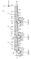
図1は、本発明の第1実施形態のLED面光源装置1の概略的な断面図である。図1に示すように、LED面光源装置1は、同一形態の複数の面光源装置ユニット1a,1b,1cが連続して配置された、いわゆるタンデム型の構成を備えている。
Hereinafter, embodiments of the LED surface light source device of the present invention will be described with reference to the accompanying drawings.
FIG. 1 is a schematic cross-sectional view of an LED surface light source device 1 according to a first embodiment of the present invention. As shown in FIG. 1, the LED surface light source device 1 has a so-called tandem configuration in which a plurality of surface light
各面光源装置ユニット1a,1b,1cは、1列に配置された上面出射タイプ(発光面に垂直な方向に光出射するタイプで、レンズをつけコリメートするものを含む)のLEDを用いたLEDアレイ光源2を備えている。また、各LED光源は、複数の赤色の単色光を発する赤色LED2a、緑色の単色光を発する緑色LED2b、青色の単色光を発する青色LED2cによって構成されている。従って、本実施例のLED面光源装置1は、RGB−LED面光源装置である。
Each surface light
各面光源装置ユニット1a,1b,1cは、さらに、単色光混合部材4と、導光板6とを備えている。単色光混合部材4は、LEDアレイ光源2を構成する赤色LED2a、緑色LED2b、青色LED2cからの波長が異なる単色光を混合しながら導光板6に導く機能を備えている。
Each surface light
導光板6は、水平に配置された上側出射面6aと、上側出射面6aに対して傾斜した下側面6bとを備えた「くさび形」の断面形状を有している。導光板6の厚い側の側端面6cは、上側出射面6aと直交する方向に対して傾斜し配置されている。単色混合部材4を介してこの厚い側の側端面6cに沿ってLEDアレイ光源2の列が配置されている。
導光板6の下側面6bには、図1のX方向に延びる三角柱のプリズムが並列配置されたプリズム部8が形成され、プリズム部8の下方には、銀蒸着反射或いは白色拡散反射板10が配置されている。
The
A
導光板6の上側出射面6aは、エッチングやブラスト処理等により、金型に微細な凹凸形状を有するマットに加工し、射出成形によりマット12を転写している。このマット12の平均的な傾斜角は2〜6°程度であり、その角度に対応するZ方向に延びる三角注プリズムを形成することでも可能である。マット12の上方には、プリズムシート14が配置されている。プリズムシート14は、下側面に、図1のZ方向に延びる三角柱のプリズムが並列配置されている。
The
本実施形態における導光体6の出射面6aに形成されるマット面は、平均傾斜角θaが0.5〜20度の範囲とすることが、出射面6a内での輝度の均斉度を図る点から好ましい。この平均傾斜角θaは、さらに好ましくは1〜15度の範囲であり、より好ましくは1.5〜12度の範囲である。これは、マット面の平均傾斜角θaが0.5度より小さくなると導光体6から出射する光量が少なくなり十分な輝度が得られなくなる傾向にあり、平均傾斜角θaが15度より大きくなると端面近傍で多量の光が出射して、出射面32内でのX方向における出射光の減衰が著しくなり、出射面6aでの輝度の均斉度が低下する傾向にあるためである。
このように導光体6の平均傾斜角θaを0.5〜20度とすることにより、出射面から出射する光の出射光光度分布(XZ面内)におけるピーク光の角度が光出射面の法線に対し50〜80度の範囲にあり、半値全幅が10〜40度であるような指向性の高い出射特性の光を導光体6から出射させることができ、その出射方向をプリズムシート14で効率的に偏向させることができ、高い輝度を有する面光源装置を提供することができる。
In the present embodiment, the mat surface formed on the
Thus, by setting the average inclination angle θa of the
ここで、平均傾斜角θaは、ISO4287/1−1984に従って、触針式表面粗さ計を用いて粗面形状を測定し、測定方向の座標をxとして、得られた傾斜関数f(x)から次の式(1)および式(2)
Δa=(1/L)∫0 L|(d/dx)f(x)|dx ・・・ (1)
θa=tan-1(Δa) ・・・ (2)
を用いて求めることができる。なお、Lは測定長さであり、Δaは平均傾斜角θaの正接である。
なお、このようなマット面に変えて上記平均傾斜角θaの範囲内であれば、Z方向に延びる多数のレンズ列を形成したレンズ面としてもよい。この場合、形成するレンズ列として、プリズム列、レンチキュラーレンズ列、V字状溝等が挙げられる。
また、導光体6の下面6bに形成されるプリズム列は、導光体6からの出射光のYZ面での指向性を制御するものであり、その頂角を85〜110度の範囲とすることが好ましい。これは、頂角をこの範囲とすることによって導光体6からの出射光を適度に集光させることができ、面状光源装置としての輝度の向上を図ることができるためであり、より好ましくは90〜100度の範囲である。
Here, the average inclination angle θa is measured in accordance with ISO 4287 / 1-1984 using a stylus type surface roughness meter, and the obtained inclination function f (x) is obtained by setting the coordinate in the measurement direction as x. To the following equations (1) and (2)
Δa = (1 / L) ∫ 0 L | (d / dx) f (x) | dx (1)
θa = tan −1 (Δa) (2)
Can be obtained using Note that L is the measurement length, and Δa is the tangent of the average inclination angle θa.
In addition, as long as it is in the range of the said average inclination | tilt angle (theta) a instead of such a mat surface, it is good also as a lens surface which formed many lens rows extended in a Z direction. In this case, examples of the lens array to be formed include a prism array, a lenticular lens array, and a V-shaped groove.
The prism row formed on the
本実施形態においては多数のプリズム列を形成したプリズム面としたが、プリズム列以外のレンチキュラーレンズ列、V字状溝等のレンズ列をX方向に延びるようにして形成したものでもよい。また、プリズム列等の頂部あるいは谷部を平坦あるいは曲面に形成してもよい。
さらに、本実施形態では、出射面6aにマット面を、下面6bにプリズム面を形成しているが、これとは逆に、出射面6aにプリズム面を形成し、下面6bをマット面とするものであってもよい。
In the present embodiment, the prism surface is formed with a large number of prism rows. However, lens rows other than the prism rows, such as lenticular lens rows and V-shaped grooves, may be formed so as to extend in the X direction. Moreover, you may form the top part or trough part, such as a prism row | line | column, in flat or a curved surface.
Further, in the present embodiment, a matte surface is formed on the
さらに、導光体6に微量の拡散剤を分散させたり、6b面にXZ平面内の導光板6の出射量を均一化するための機構として凹凸をつけ、さらに導光板6の上に拡散フィルムおよび上側面にZ方向に延びる三角柱のプリズムが並列配置されているプリズムシートを配置した形であっても良い。
Further, a minute amount of a diffusing agent is dispersed in the
単色光混合部材4は、LEDアレイ光源2側に位置し導光板6の上側出射面6aと直交する方向に延びる入射部分4aと、導光板6側に位置し導光板6の上側出射面6aに直交する方向に対して傾いて延びる傾斜部分(出射部分)4bとを備えている。
単色光混合部材4の入射部分4aの端面4cは、導光板6の上側出射面6aと平行に配置され、この端面4cに対向して、LEDアレイ光源2が配置されている。
単色光混合部材4の出射部分4bの端面4dは、導光板6の厚い側の端面6cと光学的に密着させられている。ここで、「光学的に密着」とは、光透過性を有する物体どうしがその間に空気層を形成することなく密着している状態をいう。
この結果、LEDアレイ光源2は、導光板6の厚い側の端面6cから上下方向にオフセットした位置に配置されている。
The monochromatic
The end surface 4c of the incident portion 4a of the monochromatic
The
As a result, the LED array
単色光混合部材4の側面4eには、反射材として銀蒸着反射フィルムまたは白色拡散反射フィルム16が配置されている。
On the
単色光混合部材4及び導光板6は、PMMA(ポリメチルメタクリレート)等の透明樹脂で形成されている。また、導光板6は、本実施形態では、上面6aの長さL=150mm、最大厚さd1=2.2mm、最小厚さd2=0.7mmに設定されているが、これに限定されるものではない。単色光混合部材4の4c面の幅は、LED光源のレンズ形状と単色光混合部材までの距離に依存するが、5.0mmに設定されている。
The monochromatic
単色光混合部材4および/または導光板6には拡散剤を含有させ、内部を透過する光を拡散させてミキシングを増進させる構成としてもよい。さらに、単色光混合部材4の入射部分4aの端面4cおよび出射部分4bの端面4dを、マットやプリズム状に加工した構成でもよい。
The monochromatic
次に、第1実施形態によるLED面光源装置1の作用について説明する。
図1に矢印で示すように各LED2a,2b,2cの発光部3から上方に向かって出射した単色光は、単色光混合部材4の入射部分4aの端面4cから単色光混合部材4に入射する。単色光混合部材4に入射した単色光は、反射フィルム16によって反射され単色光混合部材4内を伝搬しながらミキシングされて白色光となる。
Next, the operation of the LED surface light source device 1 according to the first embodiment will be described.
As indicated by arrows in FIG. 1, the monochromatic light emitted upward from the light emitting portion 3 of each
白色光は、単色光混合部材4の出射部分4bの端面4dから導光板6の厚い側の端面6cを通って導光板6に入射し、導光板6の内部を伝搬する。この白色光は、導光板6の下側6bに形成されたプリズム8やその下方に設けられた反射板10によって反射され、導光板6の上側出射面6a方向に偏向され、マット12の傾斜で臨界角を越えた光は、上側出射面6aから出射する。プリズムシート14によって、上側出射面6aに直交する方向に偏向される。
White light enters the
上述した本実施形態のLED面光源装置1によれば、単色光を混合(ミキシング)して白色光とする単色光混合部材が、導光板6の上側出射面6aに直交する方向に対して傾いて延びる傾斜部分(出射部分)4bを備えている。すなわち、単色光混合部材の一部が、面光源装置の厚さ方向に対して傾斜して配置されているので、LEDアレイ光源2が前記導光板の厚い側の端面から上下方向にオフセットした位置に配置でき、パッケージの大きな高出力LEDを使用し、白色を作るに十分な長いミキシング長を取ることが可能となる。従って、LED面光源装置の厚さを抑制することができる。
According to the LED surface light source device 1 of the present embodiment described above, the monochromatic light mixing member that mixes (mixes) monochromatic light into white light is inclined with respect to the direction orthogonal to the
また、各LED2a,2b,2cから発光された各単色光は、単色光混合部材4で効率よく混合させられて白色光となるので、色むらが少なく、純度の高い白色光を導光板6の上側出射面6aから全体から均一に出射させることができる。
Further, each monochromatic light emitted from each
つぎに、本発明の第2実施形態によるLED面光源装置を説明する。
図2は、本発明の第2実施形態のLED面光源装置20の構成を示す概略的な断面図である。図2に示されているように、第2実施形態のLED面光源装置20は、第1実施形態のLED面光源装置1と基本的には同一の構成を備えている。したがって、図2では、図1と同一の部分については同一の符号を付し、それらの説明は省略する。
Next, an LED surface light source device according to a second embodiment of the present invention will be described.
FIG. 2 is a schematic cross-sectional view showing the configuration of the LED surface
第2実施形態のLED面光源装置20と第1実施態様のLED面光源装置1との相違は、LEDアレイ光源2からの光の出射方向および単色光混合部材の形状である。
図2に示すように、LED面光源装置20では、第1実施形態のLED面光源装置1で使用した上面出射タイプ(発光面に垂直な方向に光出射するタイプで、レンズをつけコリメートするものを含む)のLEDを用いたLEDアレイ光源2に代えて、側方出射タイプのLED(発光面に水平な方向に光出射するタイプ)を用いたLEDアレイ光源22が使用されている。
The differences between the LED surface
As shown in FIG. 2, the LED surface
また、LED面光源装置20では、台形状の断面形状を有する単色光混合部材24が使用されている。LED面光源装置20では、単色光混合部材24が導光板6の上側出射面6aに直交する方向に対して傾斜して延びるように配置されている。また、台形状の単色光混合部材24は、下底24aがLEDアレイ光源22に対向して配置され、上底24bが導光板6の厚い側の端面6cに光学的に密着させられている。
In the LED surface
各LEDアレイ光源22は、赤色の単色光を発する赤色LED22a、緑色の単色光を発する緑色LED22b、青色の単色光を発する青色LED22cから構成されている。各LEDアレイ光源22の発光部23は、図2に矢印で示すように、側方に向けて(発光面に水平な方向に)単色光を出射するようなレンズ設計のLEDモジュールを使用している。
各LEDアレイ光源22は、導光板6の上側出射面6aに直交する方向に対して傾いて配置された単色光混合部材24の下底24bに、出射した単色光が略垂直方向から入射するように傾斜して配置されている(図2)。また、LEDアレイ光源22の背面および上面には反射板25が配置されている。
この結果、LEDアレイ光源22の列は、導光板6の厚い側の端面6cから上下方向にオフセットした位置に配置される。
Each LED array
Each LED array
As a result, the rows of the LED array
上述した本実施形態のLED面光源装置20によれば、単色光を混合(ミキシング)して白色光とする単色光混合部材が、導光板6の上側出射面6aに直交する方向に対して傾いて延びているので、LEDアレイ光源2が前記導光板の厚い側の端面から上下方向にオフセットした位置に配置でき、パッケージの大きな高出力LEDを使用し、白色を作るに十分な長いミキシング長を取ることが可能となる。従って、LED面光源装置の厚さを抑制することができる。
According to the LED surface
つぎに、本発明の第3実施形態によるLED面光源装置を説明する。
図3は、本発明の第3実施形態のLED面光源装置30の構成を示す概略的な断面図である。図3に示されているように、第3実施形態のLED面光源装置30は、第1のLED面光源装置1と基本的には同一の構成を備えている。したがって、図3では、図1と同一の部分については同一の符号を付し、それらの説明は省略する。
Next, an LED surface light source device according to a third embodiment of the present invention will be described.
FIG. 3 is a schematic cross-sectional view showing the configuration of the LED surface
第3実施形態のLED面光源装置30と第1実施態様のLED面光源装置1との相違は、LEDアレイ光源の方向と単色光混合部材の形状である。
図3に示すように、LED面光源装置20の単色光混合部材34は、LEDアレイ光源側に位置し導光板6の上側出射面6aと平行に延びる入射部分34aと、導光板6側に位置し上側出射面6aに直交する方向に対して傾いて延びる傾斜部分(出射部分)34bとを備えている。
The difference between the LED surface
As shown in FIG. 3, the monochromatic
また、LEDアレイ光源32としては、第1実施形態と同様の上面出射タイプ(発光面に垂直な方向に光出射するタイプで、レンズをつけコリメートするものを含む)LEDを用いたLEDアレイ光源32が使用されている。LEDアレイ光源32は、構成する各LEDの発光部33からLEDの上方に向かって出射した単色光が、上側出射面6aに直交する方向に延びる入射部分34の端面34cに垂直に入射するように、90度倒した状態に配置されている。さらに、単色光混合部材34は、導光板6の上側出射面6aに直交する方向に対して傾いて延びる傾斜部分(出射部分)34bを備えている。この結果、LEDアレイ光源32の列は、導光板6の厚い側の端面6cから上下方向にオフセットした位置に配置されている。
Further, as the LED array
すなわち、単色光混合部材の一部が、面光源装置の厚さ方向に対して傾斜して配置されているので、LEDアレイ光源2が前記導光板の厚い側の端面から上下方向にオフセットした位置に配置でき、パッケージの大きな高出力LEDを使用し、白色を作るに十分な長いミキシング長を取ることが可能となる。従って、LED面光源装置の厚さを抑制することができる。
That is, since a part of the monochromatic light mixing member is arranged to be inclined with respect to the thickness direction of the surface light source device, the position where the LED array
本発明の上記実施形態に限定されることなく、特許請求の範囲に記載された技術的思想の範囲内で種々の変更、変形が可能である。 The present invention is not limited to the above-described embodiment, and various changes and modifications can be made within the scope of the technical idea described in the claims.
1,20,30 LED面光源装置
2,22,32 LEDアレイ光源
4,24,34 単色光混合部材
6 導光板
8 プリズム
10 反射板
12 マット
14 プリズムシート
16 銀蒸着フィルムまたは白色拡散反射フィルム
25 LED光源反射板
DESCRIPTION OF
Claims (5)
前記各導光板の厚い側の端面に沿って配置される複数のLEDアレイ光源と、
前記各導光板の厚い側の端面と前記各LEDアレイ光源との間に配置され、前記各LEDアレイ光源を構成するLED光源から発せられた波長が異なる単色光を混合しながら前記各導光板の厚い側の端面に導く単色光混合部材とを備え、
該単色光混合部材が、前記上側出射面に直交する方向に対して傾いて延びる傾斜部分を含み、
前記LEDアレイ光源が前記導光板の厚い側の端面から上下方向にオフセットした位置に配置されている、
ことを特徴とするLED面光源装置。 A plurality of light guide plates continuously arranged in a line with a wedge-shaped cross section constituted by a horizontal upper emission surface and an inclined lower side surface;
A plurality of LED array light sources disposed along the end face on the thick side of each light guide plate;
The light guide plate is disposed between the end face on the thick side of each light guide plate and each LED array light source, and mixed with monochromatic light having different wavelengths emitted from the LED light sources constituting each LED array light source. A monochromatic light mixing member that leads to the end face on the thick side,
The monochromatic light mixing member includes an inclined portion extending inclined with respect to a direction orthogonal to the upper emission surface,
The LED array light source is disposed at a position offset in the vertical direction from the end face on the thick side of the light guide plate,
An LED surface light source device.
請求項1に記載のLED面光源装置。 The LED surface light source device according to claim 1, wherein each of the LED array light sources includes a red LED that emits red monochromatic light, a green LED that emits green monochromatic light, and a blue LED that emits blue monochromatic light. .
請求項1または2に記載のLED面光源装置。 The monochromatic light mixing member is located on the LED array light source side and extends in a direction perpendicular to the upper light emitting surface of the light guide plate, and the direction located on the light guide plate side and perpendicular to the upper light emitting surface An exit portion that constitutes an inclined portion extending in an inclined manner,
The LED surface light source device according to claim 1 or 2.
請求項1または2に記載のLED面光源装置。 One end of the inclined portion is arranged to face the LED array light source, and the other end is connected to the end surface on the thick side of the light guide plate.
The LED surface light source device according to claim 1 or 2.
請求項1または2に記載のLED面光源装置。 The monochromatic light mixing member is located on the LED array light source side and extends in parallel with the upper light exit surface of the light guide plate, and is inclined with respect to a direction located on the light guide plate side and perpendicular to the upper light exit surface. An exit portion constituting an extending inclined portion,
The LED surface light source device according to claim 1 or 2.
Priority Applications (1)
| Application Number | Priority Date | Filing Date | Title |
|---|---|---|---|
| JP2005089243A JP2006269364A (en) | 2005-03-25 | 2005-03-25 | LED surface light source device |
Applications Claiming Priority (1)
| Application Number | Priority Date | Filing Date | Title |
|---|---|---|---|
| JP2005089243A JP2006269364A (en) | 2005-03-25 | 2005-03-25 | LED surface light source device |
Publications (1)
| Publication Number | Publication Date |
|---|---|
| JP2006269364A true JP2006269364A (en) | 2006-10-05 |
Family
ID=37205081
Family Applications (1)
| Application Number | Title | Priority Date | Filing Date |
|---|---|---|---|
| JP2005089243A Pending JP2006269364A (en) | 2005-03-25 | 2005-03-25 | LED surface light source device |
Country Status (1)
| Country | Link |
|---|---|
| JP (1) | JP2006269364A (en) |
Cited By (28)
| Publication number | Priority date | Publication date | Assignee | Title |
|---|---|---|---|---|
| WO2008058575A1 (en) * | 2006-11-17 | 2008-05-22 | Osram Gesellschaft mit beschränkter Haftung | Modular surface lighting system |
| WO2008136349A1 (en) * | 2007-04-26 | 2008-11-13 | Sharp Kabushiki Kaisha | Light emitting element and liquid crystal display device |
| WO2009017006A1 (en) * | 2007-07-27 | 2009-02-05 | Sharp Kabushiki Kaisha | Chassis, illuminating device provided with the chassis, and display device |
| WO2009016910A1 (en) * | 2007-07-27 | 2009-02-05 | Sharp Kabushiki Kaisha | Lighting device and liquid crystal display |
| JP2009205827A (en) * | 2008-02-26 | 2009-09-10 | Ritsumeikan | Backlight device |
| JP2009218175A (en) * | 2008-03-12 | 2009-09-24 | Stanley Electric Co Ltd | Light guide plate, and surface light source lighting system |
| WO2010010742A1 (en) * | 2008-07-22 | 2010-01-28 | シャープ株式会社 | Lighting unit, lighting device, and liquid crystal display device |
| WO2010064473A1 (en) * | 2008-12-05 | 2010-06-10 | シャープ株式会社 | Illumination device, display device, and television reception device |
| JP2010161029A (en) * | 2009-01-09 | 2010-07-22 | Sharp Corp | Back light unit and liquid crystal display device equipped with this |
| CN101852395A (en) * | 2010-06-22 | 2010-10-06 | 上海向隆电子科技有限公司 | Light guide component |
| WO2011016610A1 (en) * | 2009-08-02 | 2011-02-10 | Lg Electronics Inc. | Backlight unit and display apparatus including the same |
| WO2011025106A1 (en) * | 2009-08-27 | 2011-03-03 | Lg Electronics Inc. | Backlight unit and display apparatus including the same |
| CN102004355A (en) * | 2009-08-31 | 2011-04-06 | 日立民用电子株式会社 | Liquid crystal display device |
| US8113704B2 (en) | 2008-05-27 | 2012-02-14 | Lg Electronics Inc. | Backlight unit having light guide plates |
| US8220981B2 (en) | 2008-05-27 | 2012-07-17 | Lg Electronics Inc. | Liquid crystal display having a plurality of modules |
| US8317387B2 (en) | 2009-06-15 | 2012-11-27 | Lg Electronics Inc. | Light emitting diode package, and backlight unit and display device using the same |
| JP2013026007A (en) * | 2011-07-20 | 2013-02-04 | Panasonic Corp | Lighting unit and lighting structure |
| CN102914814A (en) * | 2011-08-04 | 2013-02-06 | 富泰华工业(深圳)有限公司 | Light guide pillar and shell subassembly provided with light guide pillar |
| US8469575B2 (en) | 2007-05-20 | 2013-06-25 | 3M Innovative Properties Company | Backlight and display system using same |
| US8523419B2 (en) | 2007-05-20 | 2013-09-03 | 3M Innovative Properties Company | Thin hollow backlights with beneficial design characteristics |
| US8608363B2 (en) | 2007-05-20 | 2013-12-17 | 3M Innovative Properties Company | Recycling backlights with semi-specular components |
| US8674929B2 (en) | 2009-12-14 | 2014-03-18 | Lg Electronics Inc. | Optical assembly, backlight unit including the same, and display apparatus including the backlight unit |
| US8757858B2 (en) | 2008-06-04 | 2014-06-24 | 3M Innovative Properties Company | Hollow backlight with tilted light source |
| US8848132B2 (en) | 2008-02-07 | 2014-09-30 | 3M Innovative Properties Company | Hollow backlight with structured films |
| US8872992B2 (en) | 2009-06-23 | 2014-10-28 | Lg Innotek Co., Ltd. | Optical assembly, backlight unit including the same, and display apparatus including the backlight unit |
| US9028108B2 (en) | 2007-05-20 | 2015-05-12 | 3M Innovative Properties Company | Collimating light injectors for edge-lit backlights |
| US9541698B2 (en) | 2008-02-22 | 2017-01-10 | 3M Innovative Properties Company | Backlights having selected output light flux distributions and display systems using same |
| US20190235149A1 (en) * | 2016-12-23 | 2019-08-01 | Wuhan China Star Optoelectronics Technology Co., Ltd. | Light guide plate and liquid crystal module |
-
2005
- 2005-03-25 JP JP2005089243A patent/JP2006269364A/en active Pending
Cited By (40)
| Publication number | Priority date | Publication date | Assignee | Title |
|---|---|---|---|---|
| WO2008058575A1 (en) * | 2006-11-17 | 2008-05-22 | Osram Gesellschaft mit beschränkter Haftung | Modular surface lighting system |
| WO2008136349A1 (en) * | 2007-04-26 | 2008-11-13 | Sharp Kabushiki Kaisha | Light emitting element and liquid crystal display device |
| US8154689B2 (en) | 2007-04-26 | 2012-04-10 | Sharp Kabushiki Kaisha | Light emitting element and liquid crystal display apparatus |
| US8740442B2 (en) | 2007-05-20 | 2014-06-03 | 3M Innovative Properties Company | Backlight and display system using same |
| US8926159B2 (en) | 2007-05-20 | 2015-01-06 | 3M Innovative Properties Company | Thin hollow backlights with beneficial design characteristics |
| US8469575B2 (en) | 2007-05-20 | 2013-06-25 | 3M Innovative Properties Company | Backlight and display system using same |
| US8523419B2 (en) | 2007-05-20 | 2013-09-03 | 3M Innovative Properties Company | Thin hollow backlights with beneficial design characteristics |
| US9091408B2 (en) | 2007-05-20 | 2015-07-28 | 3M Innovative Properties Company | Recycling backlights with semi-specular components |
| US9028108B2 (en) | 2007-05-20 | 2015-05-12 | 3M Innovative Properties Company | Collimating light injectors for edge-lit backlights |
| US8608363B2 (en) | 2007-05-20 | 2013-12-17 | 3M Innovative Properties Company | Recycling backlights with semi-specular components |
| WO2009016910A1 (en) * | 2007-07-27 | 2009-02-05 | Sharp Kabushiki Kaisha | Lighting device and liquid crystal display |
| US7796209B2 (en) | 2007-07-27 | 2010-09-14 | Sharp Kabushiki Kaisha | Illumination device and liquid crystal display device |
| CN101668988B (en) * | 2007-07-27 | 2011-06-15 | 夏普株式会社 | Lighting device and liquid crystal display device |
| JP4838355B2 (en) * | 2007-07-27 | 2011-12-14 | シャープ株式会社 | Illumination device and liquid crystal display device |
| WO2009017006A1 (en) * | 2007-07-27 | 2009-02-05 | Sharp Kabushiki Kaisha | Chassis, illuminating device provided with the chassis, and display device |
| US8848132B2 (en) | 2008-02-07 | 2014-09-30 | 3M Innovative Properties Company | Hollow backlight with structured films |
| US9541698B2 (en) | 2008-02-22 | 2017-01-10 | 3M Innovative Properties Company | Backlights having selected output light flux distributions and display systems using same |
| JP2009205827A (en) * | 2008-02-26 | 2009-09-10 | Ritsumeikan | Backlight device |
| JP2009218175A (en) * | 2008-03-12 | 2009-09-24 | Stanley Electric Co Ltd | Light guide plate, and surface light source lighting system |
| US8220981B2 (en) | 2008-05-27 | 2012-07-17 | Lg Electronics Inc. | Liquid crystal display having a plurality of modules |
| US8189135B2 (en) | 2008-05-27 | 2012-05-29 | Lg Electronics Inc. | LED back-light unit and liquid crystal display device using the same |
| US8113704B2 (en) | 2008-05-27 | 2012-02-14 | Lg Electronics Inc. | Backlight unit having light guide plates |
| US8757858B2 (en) | 2008-06-04 | 2014-06-24 | 3M Innovative Properties Company | Hollow backlight with tilted light source |
| WO2010010742A1 (en) * | 2008-07-22 | 2010-01-28 | シャープ株式会社 | Lighting unit, lighting device, and liquid crystal display device |
| CN102239360A (en) * | 2008-12-05 | 2011-11-09 | 夏普株式会社 | Illumination device, display device, and television reception device |
| WO2010064473A1 (en) * | 2008-12-05 | 2010-06-10 | シャープ株式会社 | Illumination device, display device, and television reception device |
| JP2010161029A (en) * | 2009-01-09 | 2010-07-22 | Sharp Corp | Back light unit and liquid crystal display device equipped with this |
| US8317387B2 (en) | 2009-06-15 | 2012-11-27 | Lg Electronics Inc. | Light emitting diode package, and backlight unit and display device using the same |
| US8872992B2 (en) | 2009-06-23 | 2014-10-28 | Lg Innotek Co., Ltd. | Optical assembly, backlight unit including the same, and display apparatus including the backlight unit |
| US9262971B2 (en) | 2009-06-23 | 2016-02-16 | Lg Innotek Co., Ltd. | Optical assembly, backlight unit including the same, and display apparatus including the backlight unit |
| WO2011016610A1 (en) * | 2009-08-02 | 2011-02-10 | Lg Electronics Inc. | Backlight unit and display apparatus including the same |
| WO2011025106A1 (en) * | 2009-08-27 | 2011-03-03 | Lg Electronics Inc. | Backlight unit and display apparatus including the same |
| US8243231B2 (en) | 2009-08-27 | 2012-08-14 | Lg Electronics Inc. | Backlight unit and display apparatus including the same |
| CN102004355A (en) * | 2009-08-31 | 2011-04-06 | 日立民用电子株式会社 | Liquid crystal display device |
| US8674929B2 (en) | 2009-12-14 | 2014-03-18 | Lg Electronics Inc. | Optical assembly, backlight unit including the same, and display apparatus including the backlight unit |
| CN101852395A (en) * | 2010-06-22 | 2010-10-06 | 上海向隆电子科技有限公司 | Light guide component |
| JP2013026007A (en) * | 2011-07-20 | 2013-02-04 | Panasonic Corp | Lighting unit and lighting structure |
| CN102914814A (en) * | 2011-08-04 | 2013-02-06 | 富泰华工业(深圳)有限公司 | Light guide pillar and shell subassembly provided with light guide pillar |
| CN102914814B (en) * | 2011-08-04 | 2014-02-26 | 富泰华工业(深圳)有限公司 | Light guide column and housing assembly equipped with the light guide column |
| US20190235149A1 (en) * | 2016-12-23 | 2019-08-01 | Wuhan China Star Optoelectronics Technology Co., Ltd. | Light guide plate and liquid crystal module |
Similar Documents
| Publication | Publication Date | Title |
|---|---|---|
| JP2006269364A (en) | LED surface light source device | |
| JP5241068B2 (en) | Side light emitting device, backlight unit using the same as light source, and liquid crystal display device using the same | |
| CN100421000C (en) | Backlight unit and liquid crystal display using the backlight unit | |
| JP4902566B2 (en) | Surface illumination device and display device | |
| US8684588B2 (en) | Light guide elements for display device | |
| KR100644684B1 (en) | Straight Side Light Emitter, Backlight System and Liquid Crystal Display Apparatus | |
| JP5085864B2 (en) | Backlight system and liquid crystal display device employing the same | |
| JP5178460B2 (en) | Surface lighting device | |
| TWI408463B (en) | Light source module and illumination apparatus | |
| JP4854497B2 (en) | Liquid crystal display | |
| JP2006221922A (en) | LED surface light source device | |
| JP2012234675A (en) | Planar lighting device | |
| JP2004038108A (en) | Light guide plate and surface lighting device | |
| KR20140058837A (en) | Optical sheet and a backlight assembly having the same | |
| JP2020013714A (en) | Planar luminaire | |
| JP4774035B2 (en) | Surface light source and display device | |
| JP4702176B2 (en) | Backlight and liquid crystal display device | |
| WO2008047442A1 (en) | Surface light source device | |
| JP2008262766A (en) | Light guide plate, surface light source device, and liquid crystal display device | |
| JP4389529B2 (en) | Surface illumination device and light guide plate | |
| JP2008053009A (en) | Light guide plate, and surface light emitting device | |
| WO2006057282A1 (en) | Light guide plate for display device | |
| KR20030078529A (en) | Backlight unit | |
| JP2010067568A (en) | Light guide plate | |
| JP2008282688A (en) | Flat light emitting device |