[go: up one dir, main page]

JP2006255253A - Electric vacuum cleaner - Google Patents

Electric vacuum cleaner Download PDF

Info

Publication number
JP2006255253A
JP2006255253A JP2005078885A JP2005078885A JP2006255253A JP 2006255253 A JP2006255253 A JP 2006255253A JP 2005078885 A JP2005078885 A JP 2005078885A JP 2005078885 A JP2005078885 A JP 2005078885A JP 2006255253 A JP2006255253 A JP 2006255253A
Authority
JP
Japan
Prior art keywords
dust
dust collecting
unit
vacuum cleaner
filter
Prior art date
Legal status (The legal status is an assumption and is not a legal conclusion. Google has not performed a legal analysis and makes no representation as to the accuracy of the status listed.)
Withdrawn
Application number
JP2005078885A
Other languages
Japanese (ja)
Inventor
Hiroshi Mori
宏 森
Current Assignee (The listed assignees may be inaccurate. Google has not performed a legal analysis and makes no representation or warranty as to the accuracy of the list.)
Panasonic Holdings Corp
Original Assignee
Matsushita Electric Industrial Co Ltd
Priority date (The priority date is an assumption and is not a legal conclusion. Google has not performed a legal analysis and makes no representation as to the accuracy of the date listed.)
Filing date
Publication date
Application filed by Matsushita Electric Industrial Co Ltd filed Critical Matsushita Electric Industrial Co Ltd
Priority to JP2005078885A priority Critical patent/JP2006255253A/en
Publication of JP2006255253A publication Critical patent/JP2006255253A/en
Withdrawn legal-status Critical Current

Links

Images

Landscapes

  • Filters For Electric Vacuum Cleaners (AREA)

Abstract

【課題】フィルター面積が小さく、集塵性能がよい小型の電気掃除機を提供すること。
【解決手段】集塵部5に設けられた、吸引風と塵埃を分離する塵埃分離部10と、塵埃分離部10により分離された塵埃を捕集する塵埃捕集部18と、集塵部5の外郭に設けられた、塵埃分離部10と塵埃捕集部18を連通する突出部19と、集塵部5の外郭に設けられ、塵埃分離部10に含塵空気を送り込むための内部空洞の連結部A14、連結部B15と、塵埃分離部10の天面内側に設けられ吸引風を通過させるメッシュフィルター16とを備え、塵埃分離部10の天面内側と前記連結部A14、連結部B15の天面内側とを略一直線上に設けた。これにより、吸引風がメッシュフィルター16を掃くように流れ塵埃が付着することがないため、フィルター面積が小さく、集塵性能がよい小型の電気掃除機を提供できるようになる。
【選択図】図2
A small vacuum cleaner having a small filter area and good dust collection performance is provided.
SOLUTION: A dust separating unit 10 for separating suction air and dust, a dust collecting unit 18 for collecting dust separated by the dust separating unit 10, and a dust collecting unit 5 provided in the dust collecting unit 5. Provided in the outer shell of the dust separating portion 10 and the dust collecting portion 18, and the outer portion of the dust collecting portion 5 provided in the outer shell of the dust collecting portion 5. A connecting portion A14, a connecting portion B15, and a mesh filter 16 provided inside the top surface of the dust separating portion 10 for allowing suction air to pass; the top surface inside of the dust separating portion 10 and the connecting portions A14, The inside of the top surface was provided on a substantially straight line. As a result, since the suction air does not flow and dust adheres so as to sweep the mesh filter 16, a small vacuum cleaner having a small filter area and good dust collection performance can be provided.
[Selection] Figure 2

Description

本発明は、一般家庭、及び業務用で使われ塵埃を捕集する電気掃除機の集塵構造に関するものである。   The present invention relates to a dust collection structure for a vacuum cleaner that is used in general households and businesses and collects dust.

従来のこの種の電気掃除機は図12のように、有底の集塵室101を設け、内部に吸気する吸気口102を集塵室101の側壁に接線方向に向け設けている。集塵室101の上端開口部103を覆うように蓋体104を設け、この蓋体104に排気口105を設ける。また集塵室101の上端開口部103を覆うようにフィルター106を取り付けている。電動送風機107が運転すると、塵埃は吸込部108より吸引され、吸気口102より集塵室101内に吸気され、集塵室101内で遠心分離され、排気はフィルター106を通して排気口105より排出される(特許文献1参照)。
特開2001−104223号公報
As shown in FIG. 12, this type of conventional vacuum cleaner is provided with a dust collection chamber 101 with a bottom, and an intake port 102 for sucking air therein is provided on the side wall of the dust collection chamber 101 in a tangential direction. A lid 104 is provided so as to cover the upper end opening 103 of the dust collection chamber 101, and an exhaust port 105 is provided in the lid 104. A filter 106 is attached so as to cover the upper end opening 103 of the dust collection chamber 101. When the electric blower 107 is operated, dust is sucked in from the suction portion 108, sucked into the dust collecting chamber 101 from the suction port 102, centrifuged in the dust collecting chamber 101, and exhaust gas is discharged from the exhaust port 105 through the filter 106. (See Patent Document 1).
JP 2001-104223 A

しかしながら、上記従来の構成では、吸気口102より吸引した塵埃がフィルター106に付着、目詰まりを起こし、集塵室101に塵埃が十分吸引されないまま吸引力が低下するということがあった。またこの目詰まり対策の為、フィルター106の面積を大きくすることもあったが、集塵室101そのものが大きくなり電気掃除機そのものが大型化してしまうという課題があった。   However, in the above-described conventional configuration, dust sucked from the air inlet 102 may adhere to the filter 106 and be clogged, and the suction force may be reduced without the dust being sufficiently sucked into the dust collection chamber 101. In order to prevent this clogging, the area of the filter 106 may be increased. However, there is a problem that the dust collection chamber 101 itself becomes large and the electric vacuum cleaner itself increases in size.

本発明は上記課題を解決するもので、吸引力が急激に低下するのを防止することで集塵性能を向上させ、かつ小型化を実現した電気掃除機を提供することを目的とする。   This invention solves the said subject, and it aims at providing the vacuum cleaner which improved dust collection performance and realized miniaturization by preventing that a suction force falls rapidly.

上記従来の課題を解決するために本発明は、吸引風を発生させる電動送風機と、前記電動送風機と連通し塵埃を吸引する吸込具と、掃除機本体から着脱自在な集塵部と、前記集塵部の内部に設けられ吸引風と塵埃を分離する塵埃分離部と、前記集塵部の内部に設けられ前記塵埃分離部により分離された塵埃を捕集する塵埃捕集部と、前記集塵部の外郭に設けられ前記塵埃分離部と塵埃捕集部を連通する突出部と、前記集塵部の外郭に設けられ、内部空洞の連結部Bを介して下流側の前記塵埃分離部に含塵空気を吸引するための内部空洞の連結部Aと、前記塵埃分離部の天面内側に設けられ吸引風を通過させるメッシュフィルターとを備え、前記塵埃分離部の天面内側と前記連結部A、Bの天面内側とを略一直線上に設けた電気掃除機としたもので、吸引風がメッシュフィルターAを掃くように流れ、塵埃がメッシュフィルターに付着することなく塵埃を分離できるため、フィルター面積の小さく集塵性能がよい小型の電気掃除機を提供することが出来る。   In order to solve the above-described conventional problems, the present invention includes an electric blower that generates suction air, a suction tool that communicates with the electric blower and sucks dust, a dust collection unit that is detachable from a cleaner body, and the dust collection unit. A dust separation part provided inside the dust part for separating suction air and dust; a dust collection part provided inside the dust collection part for collecting the dust separated by the dust separation part; and the dust collection part Provided in the outer shell of the dust collecting portion and the protruding portion communicating the dust collecting portion and the dust collecting portion, and provided in the outer shell of the dust collecting portion and included in the dust separating portion on the downstream side via the connecting portion B of the internal cavity. An internal cavity connecting portion A for sucking dust air; and a mesh filter provided inside the top surface of the dust separating portion and allowing suction air to pass therethrough; and the top surface inside of the dust separating portion and the connecting portion A A vacuum cleaner provided with the inside of the top surface of B in a substantially straight line In, suction air flows to be swept mesh filter A, since the dust can be separated dust without adhering to the mesh filter, it is possible to provide a vacuum cleaner of small dust collecting performance is good small filter area.

本発明によれば、フィルター面積が小さくても吸引力が急激に低下することを防止でき、集塵性能がよく、かつ、小型化を実現した電気掃除機を提供できる。   ADVANTAGE OF THE INVENTION According to this invention, even if a filter area is small, it can prevent that attraction | suction force falls rapidly, can provide the vacuum cleaner which realized dust collection performance and implement | achieved size reduction.

第1の発明は、吸引風を発生させる電動送風機と、前記電動送風機と連通し塵埃を吸引する吸込具と、掃除機本体から着脱自在な集塵部と、前記集塵部の内部に設けられ吸引風と塵埃を分離する塵埃分離部と、前記集塵部の内部に設けられ前記塵埃分離部により分離された塵埃を捕集する塵埃捕集部と、前記集塵部の外郭に設けられ前記塵埃分離部と塵埃捕集部を連通する突出部と、前記集塵部の外郭に設けられ、内部空洞の連結部Bを介して下流側の前記塵埃分離部に含塵空気を吸引するための内部空洞の連結部Aと、前記塵埃分離部の天面内側に設けられ吸引風を通過させるメッシュフィルターとを備え、前記塵埃分離部の天面内側と前記連結部A、Bの天面内側とを略一直線上に設けたことで、吸引風がメッシュフィルターを掃くように流れ塵埃がメッシュフィルターに付着することなく分離され、フィルター面積が小さくても集塵性能がよく、かつ、小型化の電気掃除機を提供する。   1st invention is provided in the inside of the electric blower which generates a suction | inhalation wind, the suction tool which communicates with the said electric blower, and attracts | sucks dust, a detachable dust collection part from the cleaner body, and the said dust collection part A dust separation unit that separates suction air and dust, a dust collection unit that is provided inside the dust collection unit and collects the dust separated by the dust separation unit, and an outer shell of the dust collection unit A protrusion that communicates the dust separating part and the dust collecting part, and an outer part of the dust collecting part, for sucking dust-containing air to the dust separating part on the downstream side via the connecting part B of the internal cavity A connecting portion A of an internal cavity; and a mesh filter provided inside the top surface of the dust separating portion and allowing suction air to pass therethrough; and a top surface inside of the dust separating portion and a top surface inside of the connecting portions A and B; So that the suction air sweeps the mesh filter. Flow dust is separated without adhering to the mesh filter, a small filter area may dust collecting performance even and provides a vacuum cleaner of compact.

第2の発明は、第1の発明の塵埃分離部と塵埃捕集部とを仕切る塵埃分離部底面に設けられたバイパス用の孔Aと、前記孔Aと対向して前記塵埃分離部の天面に設けられたバイパス用の孔Bと、前記塵埃分離部の上方に設けられたスポンジフィルターとを備え、前記孔A、穴Bを介して、前記塵埃捕集部と前記スポンジフィルターとを連通させたことにより、塵埃捕集部から塵埃分離部に流れる気流をつくり、塵埃捕集部内にたまる塵埃を圧縮して集塵量を増やすことができ集塵性能を向上することができる。   According to a second aspect of the present invention, there is provided a bypass hole A provided on a bottom surface of the dust separation part for partitioning the dust separation part and the dust collection part of the first invention, and a top of the dust separation part facing the hole A. A bypass hole B provided on the surface and a sponge filter provided above the dust separation part, and the dust collection part and the sponge filter communicate with each other through the hole A and hole B. By doing so, an airflow flowing from the dust collecting part to the dust separating part is created, and the amount of collected dust can be increased by compressing the dust accumulated in the dust collecting part, thereby improving the dust collecting performance.

第3の発明は、第2の発明の塵埃分離部の孔Aの下面に、ネット部材を着脱自在に設けたことにより、孔Aが詰まり難くし、吸引力が持続する電気掃除機を提供することができる。   According to a third aspect of the present invention, there is provided a vacuum cleaner in which the hole A is hardly clogged and the suction force is maintained by providing a net member detachably on the lower surface of the hole A of the dust separation portion of the second aspect of the invention. be able to.

以下、本発明の実施の形態について、図面を参照しながら説明する。なお、この実施の形態によりこの発明が限定されるものではない。   Hereinafter, embodiments of the present invention will be described with reference to the drawings. Note that the present invention is not limited to the embodiments.

(実施の形態1)
本発明の第1の実施の形態について、図1〜図4を用いて説明する。
(Embodiment 1)
A first embodiment of the present invention will be described with reference to FIGS.

図1は、本発明の電気掃除機の正面図である。本発明の電気掃除機は、下部に床面の塵埃を吸引する吸込具1、吸引風を発する電動送風機2を内蔵した掃除機本体3、掃除機本体3の上部に掃除機本体3を持ち運びする際の把手部4、掃除機本体3より着脱でき塵埃を捕集する集塵部5、この集塵部5と前記吸込具1を連通する吸引通路で、把手部4にセットされたホース6、掃除機本体3の上方に設けられ操作するときに握るハンドル7から構成されている。また、前記掃除機本体3には、電動送風機2が発する排気を排出する排出穴(図示せず)が設けられている。   FIG. 1 is a front view of the electric vacuum cleaner of the present invention. The vacuum cleaner of the present invention carries a vacuum cleaner body 3 having a suction tool 1 that sucks dust on the floor at the bottom, an electric blower 2 that emits suction air, and a vacuum cleaner body 3 above the vacuum cleaner body 3. Gripping part 4, dust collecting part 5 that can be detached from the vacuum cleaner main body 3 and collects dust, a suction passage that communicates the dust collecting part 5 and the suction tool 1, and a hose 6 set in the gripping part 4, The handle 7 is provided above the cleaner body 3 and grips when operating. Further, the cleaner body 3 is provided with a discharge hole (not shown) for discharging the exhaust generated by the electric blower 2.

ホース6は一端を掃除機本体3に固定されており、他端が着脱自在になっている。本体スイッチ8はハンドル7についている。また、電源コード9は掃除機本体3の後方からでている。   One end of the hose 6 is fixed to the cleaner body 3, and the other end is detachable. The main body switch 8 is attached to the handle 7. Further, the power cord 9 comes out from the rear of the cleaner body 3.

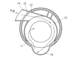
図2〜図4は、電気掃除機の集塵部5の構成を説明する集塵部5の要部断面図である。塵埃分離部10はフィルターケース11と隔壁12からなり、隔壁12は集塵部下部部材13の掃除機本体3のホース6の固定部につながる連結部A14に連結部B15はつながっている。また、フィルターケース11の中央部下面にはメッシュフィルター16が取り付けてあり、内部にスポンジフィルター17を備えている。メッシュフィルター16は連結部A14、および、連結部B15の内部上面と同じ高さにある。また、フィルターケース11と隔壁12は左右方向に回転させて取り付け取り外しができるようになっている。   2-4 is principal part sectional drawing of the dust collection part 5 explaining the structure of the dust collection part 5 of a vacuum cleaner. The dust separation unit 10 includes a filter case 11 and a partition wall 12. The partition wall 12 is connected to a connection portion A14 connected to the fixing portion of the hose 6 of the cleaner body 3 of the dust collection unit lower member 13. Further, a mesh filter 16 is attached to the lower surface of the central portion of the filter case 11, and a sponge filter 17 is provided inside. The mesh filter 16 is at the same height as the inner upper surface of the connecting portion A14 and the connecting portion B15. The filter case 11 and the partition wall 12 can be attached and detached by rotating in the left-right direction.

また、集塵部下部部材13と隔壁12とで囲まれた部分が塵埃捕集部18であり、塵埃分離部10で分離された塵埃がたまるようになっている。また、突出部19は集塵部下部部材13に構成され、塵埃捕集部18と塵埃分離部10をつなぐようにしている。   Further, a portion surrounded by the dust collecting portion lower member 13 and the partition wall 12 is a dust collecting portion 18, and the dust separated by the dust separating portion 10 is accumulated. Further, the protruding portion 19 is configured in the dust collecting portion lower member 13 so as to connect the dust collecting portion 18 and the dust separating portion 10.

フィルターケース11はパッキン20を有しており、このパッキン20で集塵蓋21とのタイト、集塵部下部部材13とのタイトを行っている。また、フィルターケース11と集塵蓋21、集塵蓋21と集塵部下部部材13は左右方向に回転させて取り付け取り外しができるようになっている。このため、フィルターケース11と集塵蓋21、フィルターケース11と隔壁12、集塵蓋21と集塵部下部部材13を取り付け取り外しする方向はすべて同じ方向になっている。このときの、保持力は集塵部下部部材13と集塵蓋21の保持力が最も軽く、隔壁12とフィルターケース11の保持力、フィルターケース11と集塵蓋21の保持力が最も高くなっていて、取り付けているのに他の部分が外れたりしないように取り付け、取り外しは同じ方向にしてある。   The filter case 11 has a packing 20, and tightness with the dust collection lid 21 and tightness with the dust collection portion lower member 13 is performed with this packing 20. Further, the filter case 11 and the dust collecting lid 21, and the dust collecting lid 21 and the dust collecting portion lower member 13 can be attached and detached by rotating in the left-right direction. For this reason, the filter case 11 and the dust collecting lid 21, the filter case 11 and the partition wall 12, and the dust collecting lid 21 and the dust collecting portion lower member 13 are attached and removed in the same direction. At this time, the holding force of the dust collecting portion lower member 13 and the dust collecting lid 21 is lightest, the holding force of the partition wall 12 and the filter case 11 and the holding force of the filter case 11 and the dust collecting lid 21 are the highest. It is attached so that other parts do not come off while it is attached, and removal is in the same direction.

また、集塵部下部部材13の連結部A14は、吸込具1よりホース5を介して塵埃を含んだ気流が流入するため、略半円形断面として気流流速を増加させている。   Moreover, since the airflow containing dust flows in through the hose 5 from the suction tool 1 to the connecting portion A14 of the dust collecting portion lower member 13, the airflow velocity is increased as a substantially semicircular cross section.

以上のように構成された電気掃除機において図1、図2を用いて、その動作を説明する。   The operation of the vacuum cleaner configured as described above will be described with reference to FIGS.

掃除機本体3の電源コード9をコンセントに差しハンドル7に設けられた本体スイッチ8を操作して、掃除機本体3を運転する。電動送風機2の吸引力で、吸込具1から床面の塵埃を吸込み、集塵部5に塵埃を捕獲する。吸込具1から吸込まれた塵埃は、掃除機本体3のホース6の固定部を通り、連結部A14、隔壁12の連結部B15を通過し、遠心力で内壁A22に沿って流れ、隔壁12と集塵部5の突出部19とでつくられた通路から塵埃捕集部18に入る。突出部19により塵埃分離部10と塵埃捕集部18はつながっており、この突出部19に沿って塵埃は塵埃捕集部18に落ちる。この時、気流は隔壁12上で突出部19の下方に行かず塵埃のみを落下させる。この気流は隔壁12の内壁A22をさらに回り、次の気流に合流する、あるいは、上方のメッシュフィルター16を通過し、スポンジフィルター17を通過し、電動送風機2に行く。   The main body switch 8 provided on the handle 7 is operated by connecting the power cord 9 of the cleaner body 3 to an outlet and the cleaner body 3 is operated. The suction force of the electric blower 2 sucks the dust on the floor surface from the suction tool 1 and captures the dust in the dust collecting part 5. The dust sucked from the suction tool 1 passes through the fixing part of the hose 6 of the cleaner body 3, passes through the connecting part A 14 and the connecting part B 15 of the partition wall 12, flows along the inner wall A 22 by centrifugal force, The dust collecting unit 18 is entered from a passage formed by the protrusion 19 of the dust collecting unit 5. The dust separating unit 10 and the dust collecting unit 18 are connected by the projecting part 19, and the dust falls on the dust collecting unit 18 along the projecting part 19. At this time, the airflow does not go below the projecting portion 19 on the partition wall 12 and only dust is dropped. This airflow further travels around the inner wall A22 of the partition wall 12 and merges with the next airflow, or passes through the upper mesh filter 16, passes through the sponge filter 17, and goes to the electric blower 2.

塵埃が塵埃捕集部18に溜まり、内部の塵埃を捨てる場合にはフィルターケース11、隔壁12が取り付いた集塵蓋21を外し、塵埃捕集部18の塵埃を捨てることができる。   When dust collects in the dust collecting part 18 and the internal dust is discarded, the dust collecting lid 21 to which the filter case 11 and the partition wall 12 are attached can be removed, and the dust in the dust collecting part 18 can be discarded.

また、内部のスポンジフィルター17をお手入れするためには、隔壁12をフィルターケース11から外し、また、フィルターケース11を集塵蓋21から外してお手入れを行う。取り付け、取り外しは爪嵌合等にて行う。   In order to clean the internal sponge filter 17, the partition wall 12 is removed from the filter case 11, and the filter case 11 is removed from the dust collection lid 21 for cleaning. Attachment and removal are performed by nail fitting.

ここで、効果を説明すると、通常はこのメッシュフィルター16に対して連結部A14、連結部B15が同じ高さにしており、気流に混じった塵埃がメッシュフィルター16の表面を流れることにより、メッシュフィルター16に塵埃が引っかかったとしても次にくる塵埃により引っかかった塵埃を除去するセルフクリーニングを行わせている。メッシュフィルター16に対して、連結部A14、連結部B15が同一高さでなく隙間があると気流がメッシュフィルターA16に対して塵埃が付着するように流れ、塵埃がとれず、すぐに吸引力が低下する。また、メッシュフィルター16の材料を金属の蒸着品を使うことにより、塵埃を滑りやすくすることができる。   Here, the effect will be described. Usually, the connecting portion A14 and the connecting portion B15 are at the same height with respect to the mesh filter 16, and the dust mixed with the airflow flows on the surface of the mesh filter 16, thereby the mesh filter. Even if the dust is caught on 16, the self-cleaning is performed to remove the dust caught by the next coming dust. If the connecting part A14 and the connecting part B15 are not at the same height and there is a gap with respect to the mesh filter 16, the airflow flows so that the dust adheres to the mesh filter A16, the dust cannot be removed, and the suction force is immediately descend. Moreover, dust can be made easy to slip by using a metal vapor-deposited material for the mesh filter 16.

また、連結部A14、連結部B15の形状を絞ることにより流入する気流の風速を増しより、塵埃がメッシュフィルター16につかないようにしている。   Further, by reducing the shape of the connecting portion A14 and the connecting portion B15, the wind speed of the inflowing air flow is increased so that the dust does not stick to the mesh filter 16.

また、塵埃は気流により突出部19に持っていかれ、穴形状によっては、気流は突出部19に入り込むが、塵埃のみ集塵捕集部18に入れ、気流はこの突出部19から出てくる。この場合、塵埃には圧縮がかからずに堆積するのみである。   Also, dust is brought to the protruding portion 19 by an air flow, and depending on the hole shape, the air flow enters the protruding portion 19, but only dust is put into the dust collecting portion 18, and the air flow comes out of the protruding portion 19. In this case, dust is deposited without being compressed.

(実施の形態2)
本発明の第2の実施の形態について図1、および図5〜図7を基に説明する。なお、上記実施の形態と同一部分については同一符号を付してその説明を省略する。
(Embodiment 2)
A second embodiment of the present invention will be described with reference to FIG. 1 and FIGS. The same parts as those in the above embodiment are denoted by the same reference numerals, and the description thereof is omitted.

隔壁12の塵埃分離部10に使われていない側にバイパス用の孔A23が設けられ、メッシュフィルターB24がついている。また、フィルターケース11も同様に塵埃分離部10に使われていない側にバイパス用の孔A23と同じバイパス用の孔B25設けられており、メッシュフィルターC26がついている。   A bypass hole A23 is provided on the side of the partition wall 12 that is not used for the dust separator 10, and a mesh filter B24 is provided. Similarly, the filter case 11 is provided with a bypass hole B25, which is the same as the bypass hole A23, on the side not used for the dust separator 10, and has a mesh filter C26.

以上のように構成された電気掃除機において図1、および図5〜図7を用いて、その動作を説明する。   The operation of the electric vacuum cleaner configured as described above will be described with reference to FIGS. 1 and 5 to 7.

掃除機本体3の電源コード9をコンセントに差しハンドル7に設けられた本体スイッチ8を操作して、掃除機本体3を運転する。電動送風機2の吸引力で、吸込具1から床面の塵埃を吸込み、集塵部5に塵埃を捕獲する。吸込具1から吸込まれた塵埃は、掃除機本体3のホース6の固定部を通り、連結部A14、隔壁12の連結部B15を通過し、遠心力で内壁A22に沿って流れ、隔壁12と集塵部5の突出部19とでつくられた通路から塵埃捕集部18に入る。突出部19により塵埃分離部10と塵埃捕集部18はつながっており、この突出部19に沿って塵埃は塵埃捕集部18に落ちる。この時、集塵捕集部18が円筒形状であれば、塵埃は、気流により回転しながら落下し、集塵捕集部18の底部でも気流により回転する。回転している気流は底面中心から上方に上がるが、重い塵埃は集塵捕集部18の底部に残し、気流だけが隔壁12のバイパス用の孔A23からさらに上方に上がり、フィルターケース11に設けられたバイパス用の孔B25を通りスポンジフィルター17を通過して掃除機本体3内の電動送風機2に気流をもどす。また、気流は塵埃を塵埃分離部10で隔壁12に沿って塵埃捕獲部18に行かせるものと、フィルターケース11に設けられたメッシュフィルター16から上方に抜け、スポンジフィルター17を通り電動送風機2に行くものがある。   The main body switch 8 provided on the handle 7 is operated by connecting the power cord 9 of the cleaner body 3 to an outlet and the cleaner body 3 is operated. The suction force of the electric blower 2 sucks the dust on the floor surface from the suction tool 1 and captures the dust in the dust collecting part 5. The dust sucked from the suction tool 1 passes through the fixing part of the hose 6 of the cleaner body 3, passes through the connecting part A 14 and the connecting part B 15 of the partition wall 12, flows along the inner wall A 22 by centrifugal force, The dust collecting unit 18 is entered from a passage formed by the protrusion 19 of the dust collecting unit 5. The dust separating unit 10 and the dust collecting unit 18 are connected by the projecting part 19, and the dust falls on the dust collecting unit 18 along the projecting part 19. At this time, if the dust collection part 18 is cylindrical, the dust falls while rotating by the air current, and also rotates by the air current at the bottom of the dust collection part 18. The rotating airflow rises upward from the center of the bottom surface, but heavy dust remains at the bottom of the dust collecting portion 18, and only the airflow rises further upward from the bypass hole A23 of the partition wall 12 and is provided in the filter case 11. The air flow is returned to the electric blower 2 in the cleaner body 3 through the bypass hole B25 and the sponge filter 17. In addition, the air flow allows dust to go to the dust trap 18 along the partition wall 12 in the dust separator 10, and escapes upward from the mesh filter 16 provided in the filter case 11, passes through the sponge filter 17, and enters the electric blower 2. There is something to go.

ここで、効果を説明すると、塵埃分離部10内から突出部19を通じて塵埃捕集部18、バイパス用の孔A23、バイパス用の孔B25を通る気流をつくり、塵埃捕集部18に入る塵埃を圧縮して塵埃をたくさん入れることができる。   Here, the effect will be described. From the inside of the dust separating part 10 through the protruding part 19, an air flow passing through the dust collecting part 18, the bypass hole A 23 and the bypass hole B 25 is created, and the dust entering the dust collecting part 18 is removed. Compress and put a lot of dust.

(実施の形態3)
本発明の第3の実施の形態について図1と図8をもとに説明する。なお、上記実施の形態と同一部分については同一符号を付してその説明を省略する。
(Embodiment 3)
A third embodiment of the present invention will be described with reference to FIGS. The same parts as those in the above embodiment are denoted by the same reference numerals, and the description thereof is omitted.

隔壁12の下部に着脱自在なネット部材27が設けられている。   A detachable net member 27 is provided below the partition wall 12.

以上のように構成された電気掃除機において図1と図8を用いて、その動作を説明する。   The operation of the vacuum cleaner configured as described above will be described with reference to FIGS. 1 and 8.

掃除機本体3の電源コード9をコンセントに差しハンドル7に設けられた本体スイッチ8を操作して、掃除機本体3を運転する。電動送風機2の吸引力で、吸込具1から床面の塵埃を吸込み、集塵部5に塵埃を捕獲する。吸込具1から吸込まれた塵埃は、掃除機本体3のホース6の固定部を通り、連結部A14、隔壁12の連結部B15を通過し、遠心力で内壁A22に沿って流れ、隔壁12と集塵部5の突出部19とでつくられた通路から塵埃捕集部18に入る。突出部19により塵埃分離部10と塵埃捕集部18はつながっており、この突出部19に沿って塵埃は塵埃捕集部18に落ちる。この時、集塵捕集部18が円筒形状であれば、塵埃は、気流により回転しながら落下し、集塵捕集部18の底部でも気流により回転する。回転している気流は底面中心から上方に上がるが、重い塵埃は集塵捕集部18の底部に残し、気流だけが隔壁12の下部に設けられた着脱自在なネット部材27を通り、バイパス用の孔A23からさらに上方に上がり、フィルターケース11に設けられたバイパス用の孔B25を通りスポンジフィルター17を通過して掃除機本体3内の電動送風機2に気流をもどす。また、気流は塵埃を塵埃分離部10で隔壁12に沿って塵埃捕獲部18に行かせるものと、フィルターケース11に設けられたメッシュフィルター16から上方に抜け、スポンジフィルター17を通り電動送風機2に行くものがある。   The main body switch 8 provided on the handle 7 is operated by connecting the power cord 9 of the cleaner body 3 to an outlet and the cleaner body 3 is operated. The suction force of the electric blower 2 sucks the dust on the floor surface from the suction tool 1 and captures the dust in the dust collecting part 5. The dust sucked from the suction tool 1 passes through the fixing part of the hose 6 of the cleaner body 3, passes through the connecting part A 14 and the connecting part B 15 of the partition wall 12, flows along the inner wall A 22 by centrifugal force, The dust collecting unit 18 is entered from a passage formed by the protrusion 19 of the dust collecting unit 5. The dust separating unit 10 and the dust collecting unit 18 are connected by the projecting part 19, and the dust falls on the dust collecting unit 18 along the projecting part 19. At this time, if the dust collection part 18 is cylindrical, the dust falls while rotating by the air current, and also rotates by the air current at the bottom of the dust collection part 18. The rotating airflow rises upward from the center of the bottom surface, but heavy dust remains at the bottom of the dust collecting portion 18, and only the airflow passes through the removable net member 27 provided at the lower part of the partition wall 12 and is used for bypassing. The air flow is returned to the electric blower 2 in the cleaner body 3 through the bypass hole B25 provided in the filter case 11 and through the sponge filter 17. In addition, the air flow allows dust to go to the dust trap 18 along the partition wall 12 in the dust separator 10, and escapes upward from the mesh filter 16 provided in the filter case 11, passes through the sponge filter 17, and enters the electric blower 2. There is something to go.

ここで、効果を説明すると、塵埃分離部10内から突出部19を通じて塵埃捕集部18、バイパス用の孔A23、バイパス用の孔B25を通る気流をつくり、バイパス用の孔A23が目詰まりするのを、ネット面積の広い着脱自在なネット部材27を設けたことにより、塵埃をここで止め、バイパス用の孔A23が目詰まりしにくくし、吸引力が落ちにくくし、さらに、塵埃捕集部18に入る塵埃を圧縮して塵埃をたくさん入れることができる。   Here, the effect will be described. From the inside of the dust separator 10 through the protrusion 19, an air flow passing through the dust collecting part 18, the bypass hole A 23 and the bypass hole B 25 is created, and the bypass hole A 23 is clogged. By providing a detachable net member 27 having a large net area, the dust is stopped here, the bypass hole A23 is less likely to be clogged, the suction force is less likely to drop, and the dust collecting portion The dust entering 18 can be compressed to put a lot of dust.

(実施の形態4)
本発明の第4の実施の形態について図1、図8、及び図9をもとに説明する。なお、上記実施の形態と同一部分については同一符号を付してその説明を省略する。
(Embodiment 4)
A fourth embodiment of the present invention will be described with reference to FIGS. 1, 8, and 9. FIG. The same parts as those in the above embodiment are denoted by the same reference numerals, and the description thereof is omitted.

隔壁12の突出部19につながる部分にリブ28を設けられている。   A rib 28 is provided at a portion connected to the protruding portion 19 of the partition wall 12.

以上のように構成された電気掃除機において図1、図8、及び図9を用いて、その動作を説明する。   The operation of the vacuum cleaner configured as described above will be described with reference to FIGS. 1, 8, and 9.

掃除機本体3の電源コード9をコンセントに差しハンドル7に設けられた本体スイッチ8を操作して、掃除機本体3を運転する。電動送風機2の吸引力で、吸込具1から床面の塵埃を吸込み、集塵部5に塵埃を捕獲する。吸込具1から吸込まれた塵埃は、掃除機本体3のホース6の固定部を通り、連結部A14、隔壁12の連結部B15を通過し、遠心力で内壁A22に沿って流れ、隔壁12とリブ28が設けられた間から集塵部5の突出部19とでつくられた通路に塵埃が運ばれる。突出部19により塵埃分離部10と塵埃捕集部18はつながっており、この突出部19に沿って塵埃は塵埃捕集部18に落ちる。この時、集塵捕集部18が円筒形状であれば、塵埃は、気流により回転しながら落下し、集塵捕集部18の底部でも気流により回転する。回転している気流は底面中心から上方に上がるが、重い塵埃は集塵捕集部18の底部に残し、気流だけが隔壁12の下部に設けられた着脱自在なネット部材27を通り、バイパス用の孔A23からさらに上方に上がり、フィルターケース11に設けられたバイパス用の孔B25を通りスポンジフィルター17を通過して掃除機本体3内の電動送風機2に気流をもどす。また、気流は塵埃を塵埃分離部10で隔壁12に沿って塵埃捕獲部18に行かせるものと、フィルターケース11に設けられたメッシュフィルター16から上方に抜け、スポンジフィルター17を通り電動送風機2に行くものがある。   The main body switch 8 provided on the handle 7 is operated by connecting the power cord 9 of the cleaner body 3 to an outlet and the cleaner body 3 is operated. The suction force of the electric blower 2 sucks the dust on the floor surface from the suction tool 1 and captures the dust in the dust collecting part 5. The dust sucked from the suction tool 1 passes through the fixing part of the hose 6 of the cleaner body 3, passes through the connecting part A 14 and the connecting part B 15 of the partition wall 12, flows along the inner wall A 22 by centrifugal force, Dust is carried to the passage formed by the protruding portion 19 of the dust collecting portion 5 from the time when the rib 28 is provided. The dust separating unit 10 and the dust collecting unit 18 are connected by the projecting part 19, and the dust falls on the dust collecting unit 18 along the projecting part 19. At this time, if the dust collection part 18 is cylindrical, the dust falls while rotating by the air current, and also rotates by the air current at the bottom of the dust collection part 18. The rotating airflow rises upward from the center of the bottom surface, but heavy dust remains at the bottom of the dust collecting portion 18, and only the airflow passes through the removable net member 27 provided at the lower part of the partition wall 12 and is used for bypassing. The air flow is returned to the electric blower 2 in the cleaner body 3 through the bypass hole B25 provided in the filter case 11 and through the sponge filter 17. In addition, the air flow allows dust to go to the dust trap 18 along the partition wall 12 in the dust separator 10, and escapes upward from the mesh filter 16 provided in the filter case 11, passes through the sponge filter 17, and enters the electric blower 2. There is something to go.

ここで、効果を説明すると、塵埃分離部10内から突出部19に塵埃を流し込むのに、リブ28を設けることにより、突出部19に流れ込む気流だけにすることができ、大きな塵埃でも、塵埃捕獲部18に流し込むことができ、塵埃をたくさん入れることができる。
リブ28がない場合は、突出部19に流れ込むのと塵埃分離部10内で旋回、次の気流に合流するものがあり大きな塵埃が塵埃捕獲部18に入らず、塵埃分離部10内に止まってしまうことがあった。
Here, the effect will be described. In order to flow dust from the dust separating part 10 into the protruding part 19, by providing the ribs 28, only the airflow flowing into the protruding part 19 can be obtained, and even large dust can be captured. It can be poured into the part 18 and a lot of dust can be put in.
When there is no rib 28, there is a thing that flows into the protrusion 19, turns in the dust separator 10, and merges with the next air flow, and large dust does not enter the dust trap 18 but stops in the dust separator 10. There was a case.

(実施の形態5)
本発明の第5の実施の形態について図1、図8、及び図10をもとに説明する。なお、上記実施の形態と同一部分については同一符号を付してその説明を省略する。
(Embodiment 5)
A fifth embodiment of the present invention will be described with reference to FIGS. 1, 8, and 10. FIG. The same parts as those in the above embodiment are denoted by the same reference numerals, and the description thereof is omitted.

塵埃分離部10の突出部19につながる部分を突出部19につながる略逆R形状部29にしたことである。   That is, the part connected to the protruding part 19 of the dust separation part 10 is changed to a substantially inverted R-shaped part 29 connected to the protruding part 19.

以上のように構成された電気掃除機において図1、図8、及び図10を用いて、その動作を説明する。   The operation of the vacuum cleaner configured as described above will be described with reference to FIGS. 1, 8, and 10.

掃除機本体3の電源コード9をコンセントに差しハンドル7に設けられた本体スイッチ8を操作して、掃除機本体3を運転する。電動送風機2の吸引力で、吸込具1から床面の塵埃を吸込み、集塵部5に塵埃を捕獲する。吸込具1から吸込まれた塵埃は、掃除機本体3のホース6の固定部を通り、連結部A14、隔壁12の連結部B15を通過し、遠心力で内壁A22に沿って流れ、隔壁12と集塵部5の突出部19とでつくられた通路に塵埃が運ばれる。この時突出部19につながる隔壁12の形状を略逆R形状部29にしている。突出部19により塵埃分離部10と塵埃捕集部18はつながっており、この突出部19に沿って塵埃は塵埃捕集部18に落ちる。この時、集塵捕集部18が円筒形状であれば、塵埃は、気流により回転しながら落下し、集塵捕集部18の底部でも気流により回転する。回転している気流は底面中心から上方に上がるが、重い塵埃は集塵捕集部18の底部に残し、気流だけが隔壁12の下部に設けられた着脱自在なネット部材27を通り、バイパス用の孔A23からさらに上方に上がり、フィルターケース11に設けられたバイパス用の孔B25を通りスポンジフィルター17を通過して掃除機本体3内の電動送風機2に気流をもどす。また、気流は塵埃を塵埃分離部10で隔壁12に沿って塵埃捕獲部18に行かせるものと、フィルターケース11に設けられたメッシュフィルター16から上方に抜け、スポンジフィルター17を通り電動送風機2に行くものがある。   The main body switch 8 provided on the handle 7 is operated by connecting the power cord 9 of the cleaner body 3 to an outlet and the cleaner body 3 is operated. The suction force of the electric blower 2 sucks the dust on the floor surface from the suction tool 1 and captures the dust in the dust collecting part 5. The dust sucked from the suction tool 1 passes through the fixing part of the hose 6 of the cleaner body 3, passes through the connecting part A 14 and the connecting part B 15 of the partition wall 12, flows along the inner wall A 22 by centrifugal force, Dust is carried to the passage formed by the protruding portion 19 of the dust collecting portion 5. At this time, the shape of the partition wall 12 connected to the protruding portion 19 is a substantially inverted R-shaped portion 29. The dust separating unit 10 and the dust collecting unit 18 are connected by the projecting part 19, and the dust falls on the dust collecting unit 18 along the projecting part 19. At this time, if the dust collection part 18 is cylindrical, the dust falls while rotating by the air current, and also rotates by the air current at the bottom of the dust collection part 18. The rotating airflow rises upward from the center of the bottom surface, but heavy dust remains at the bottom of the dust collecting portion 18, and only the airflow passes through the removable net member 27 provided at the lower part of the partition wall 12 and is used for bypassing. The air flow is returned to the electric blower 2 in the cleaner body 3 through the bypass hole B25 provided in the filter case 11 and through the sponge filter 17. In addition, the air flow allows dust to go to the dust trap 18 along the partition wall 12 in the dust separator 10, and escapes upward from the mesh filter 16 provided in the filter case 11, passes through the sponge filter 17, and enters the electric blower 2. There is something to go.

ここで、効果を説明すると、塵埃分離部10内から突出部19に塵埃を流し込むのに、突出部19につながる隔壁12の形状を略逆R形状部29にしているため、角、エッジがなく気流の流れを乱すことなく、大きな塵埃を有効的に塵埃捕集部18に送り込むことができる。   Here, the effect will be described. Since the shape of the partition wall 12 connected to the protruding portion 19 is a substantially inverted R-shaped portion 29 in order to flow dust from the dust separating portion 10 into the protruding portion 19, there is no corner or edge. Large dust can be effectively fed into the dust collecting portion 18 without disturbing the flow of the airflow.

(実施の形態6)
本発明の第6の実施の形態について図1、図11をもとに説明する。なお、上記実施の形態と同一部分については同一符号を付してその説明を省略する。
(Embodiment 6)
A sixth embodiment of the present invention will be described with reference to FIGS. The same parts as those in the above embodiment are denoted by the same reference numerals, and the description thereof is omitted.

塵埃分離部10の突出部19につながる部分に、塵埃捕集部18につながるR形状部30にしたことである。   This is because the R-shaped portion 30 connected to the dust collecting portion 18 is formed in the portion connected to the protruding portion 19 of the dust separating portion 10.

以上のように構成された電気掃除機において図1、図11を用いて、その動作を説明する。   The operation of the vacuum cleaner configured as described above will be described with reference to FIGS.

掃除機本体3の電源コード9をコンセントに差しハンドル7に設けられた本体スイッチ8を操作して、掃除機本体3を運転する。電動送風機2の吸引力で、吸込具1から床面の塵埃を吸込み、集塵部5に塵埃を捕獲する。吸込具1から吸込まれた塵埃は、掃除機本体3のホース6の固定部を通り、連結部A14、隔壁12の連結部B15を通過し、遠心力で内壁A22に沿って流れ、隔壁12と集塵部5の突出部19とでつくられた通路に塵埃が運ばれる。この時突出部19につながる隔壁12の形状を塵埃捕集部18につながるR形状部30にしており、塵埃が突出部19の内部に運びこまれ易くしている。この時、集塵捕集部18が円筒形状であれば、塵埃は、気流により回転しながら落下し、集塵捕集部18の底部でも気流により回転する。回転している気流は底面中心から上方に上がるが、重い塵埃は集塵捕集部18の底部に残し、気流だけが隔壁12の下部に設けられた着脱自在なネット部材27を通り、バイパス用の孔A23からさらに上方に上がり、フィルターケース11に設けられたバイパス用の孔B25を通りスポンジフィルター17を通過して掃除機本体3内の電動送風機2に気流をもどす。また、気流は塵埃を塵埃分離部10で隔壁12に沿って塵埃捕獲部18に行かせるものと、フィルターケース11に設けられたメッシュフィルター16から上方に抜け、スポンジフィルター17を通り電動送風機2に行くものがある。   The main body switch 8 provided on the handle 7 is operated by connecting the power cord 9 of the cleaner body 3 to an outlet and the cleaner body 3 is operated. The suction force of the electric blower 2 sucks the dust on the floor surface from the suction tool 1 and captures the dust in the dust collecting part 5. The dust sucked from the suction tool 1 passes through the fixing part of the hose 6 of the cleaner body 3, passes through the connecting part A 14 and the connecting part B 15 of the partition wall 12, flows along the inner wall A 22 by centrifugal force, Dust is carried to the passage formed by the protruding portion 19 of the dust collecting portion 5. At this time, the shape of the partition wall 12 connected to the protruding portion 19 is changed to an R-shaped portion 30 connected to the dust collecting portion 18 so that dust is easily carried into the protruding portion 19. At this time, if the dust collection part 18 is cylindrical, the dust falls while rotating by the air current, and also rotates by the air current at the bottom of the dust collection part 18. The rotating airflow rises upward from the center of the bottom surface, but heavy dust remains at the bottom of the dust collecting portion 18, and only the airflow passes through the removable net member 27 provided at the lower part of the partition wall 12 and is used for bypassing. The air flow is returned to the electric blower 2 in the cleaner body 3 through the bypass hole B25 provided in the filter case 11 and through the sponge filter 17. In addition, the air flow allows dust to go to the dust trap 18 along the partition wall 12 in the dust separator 10, and escapes upward from the mesh filter 16 provided in the filter case 11, passes through the sponge filter 17, and enters the electric blower 2. There is something to go.

ここで、効果を説明すると、塵埃分離部10内から突出部19に塵埃を流し込むのに、突出部19につながる隔壁12の形状を塵埃捕集部18につながるR形状部30にしているため、塵埃が突出部19の内部に運ぶ気流をスムーズなRで導き、整流するため塵埃が、突出部19に入りやすくなっている。   Here, the effect will be described. Since the shape of the partition wall 12 connected to the protruding portion 19 is changed to the R-shaped portion 30 connected to the dust collecting portion 18 in order to flow dust from the dust separating portion 10 into the protruding portion 19, Since the airflow that the dust carries into the protrusion 19 is guided with smooth R and rectifies, the dust easily enters the protrusion 19.

(実施の形態7)
本発明の第7の実施の形態について図1、図8をもとに説明する。なお、上記実施の形態と同一部分については同一符号を付してその説明を省略する。
(Embodiment 7)
A seventh embodiment of the present invention will be described with reference to FIGS. The same parts as those in the above embodiment are denoted by the same reference numerals, and the description thereof is omitted.

塵埃分離部10の隔壁12の材料を透明部材にしたことである。   The material of the partition wall 12 of the dust separation unit 10 is a transparent member.

以上のように構成された電気掃除機において図1、図8を用いて、その動作を説明する。   The operation of the vacuum cleaner configured as described above will be described with reference to FIGS.

掃除機本体3の電源コード9をコンセントに差しハンドル7に設けられた本体スイッチ8を操作して、掃除機本体3を運転する。電動送風機2の吸引力で、吸込具1から床面の塵埃を吸込み、集塵部5に塵埃を捕獲する。吸込具1から吸込まれた塵埃は、掃除機本体3のホース6の固定部を通り、連結部A14、隔壁12の連結部B15を通過し、遠心力で内壁A22に沿って流れ、隔壁12と集塵部5の突出部19とでつくられた通路に塵埃が運ばれる。突出部19により塵埃分離部10と塵埃捕集部18はつながっており、この突出部19に沿って塵埃は塵埃捕集部18に落ちる。この時、集塵捕集部18が円筒形状であれば、塵埃は、気流により回転しながら落下し、集塵捕集部18の底部でも気流により回転する。回転している気流は底面中心から上方に上がるが、重い塵埃は集塵捕集部18の底部に残し、気流だけが隔壁12の下部に設けられた着脱自在なネット部材27を通り、バイパス用の孔A23からさらに上方に上がり、フィルターケース11に設けられたバイパス用の孔B25を通りスポンジフィルター17を通過して掃除機本体3内の電動送風機2に気流をもどす。また、気流は塵埃を塵埃分離部10で隔壁12に沿って塵埃捕獲部18に行かせるものと、フィルターケース11に設けられたメッシュフィルター16から上方に抜け、スポンジフィルター17を通り電動送風機2に行くものがある。   The main body switch 8 provided on the handle 7 is operated by connecting the power cord 9 of the cleaner body 3 to an outlet and the cleaner body 3 is operated. The suction force of the electric blower 2 sucks dust on the floor surface from the suction tool 1 and captures the dust in the dust collecting part 5. The dust sucked from the suction tool 1 passes through the fixing part of the hose 6 of the cleaner body 3, passes through the connecting part A 14 and the connecting part B 15 of the partition wall 12, flows along the inner wall A 22 by centrifugal force, Dust is carried to the passage formed by the protruding portion 19 of the dust collecting portion 5. The dust separating unit 10 and the dust collecting unit 18 are connected by the projecting part 19, and the dust falls on the dust collecting unit 18 along the projecting part 19. At this time, if the dust collection part 18 is cylindrical, the dust falls while rotating by the air current, and also rotates by the air current at the bottom of the dust collection part 18. The rotating airflow rises upward from the center of the bottom surface, but heavy dust remains at the bottom of the dust collecting portion 18, and only the airflow passes through the removable net member 27 provided at the lower part of the partition wall 12 for bypassing. The air flow is returned to the electric blower 2 in the cleaner body 3 through the bypass hole B25 provided in the filter case 11 and through the sponge filter 17. In addition, the air flow allows dust to go to the dust catcher 18 along the partition wall 12 in the dust separator 10, and escapes upward from the mesh filter 16 provided in the filter case 11, and passes through the sponge filter 17 to the electric blower 2. There is something to go.

ここで、効果を説明すると、通常集塵部5は透明部材で出来ているが、塵埃分離部10内から突出部19に塵埃を流し込むところは大きな塵埃が引っかかりやすいため、引っかかったのがすぐにわかるように塵埃分離部10を透明部材にしてよりわかりやすいようにしたことである。   Here, the effect will be explained. Normally, the dust collecting part 5 is made of a transparent member. However, when dust is poured from the dust separating part 10 into the projecting part 19, large dust is easily caught. As can be seen, the dust separator 10 is made transparent so that it can be easily understood.

以上のように、本発明にかかる電気掃除機は、塵埃の捕獲性能を高くし、集塵部のお手入れをし易くし、実用性でも極めて有用なものである。   As described above, the vacuum cleaner according to the present invention has high dust capturing performance, facilitates cleaning of the dust collecting portion, and is extremely useful in practical use.

本発明の実施の形態1〜7における電気掃除機のイメージ図The image figure of the vacuum cleaner in Embodiment 1-7 of this invention 本発明の実施の形態1における電気掃除機の集塵部の縦断面図The longitudinal cross-sectional view of the dust collection part of the vacuum cleaner in Embodiment 1 of this invention 同、電気掃除機の隔壁の要部断面図Sectional view of the main part of the partition of the vacuum cleaner 同、電気掃除機の隔壁の他の要部断面図The other main part sectional drawing of the partition of the vacuum cleaner 本発明の実施の形態2における電気掃除機の集塵部の縦断面図The longitudinal cross-sectional view of the dust collection part of the vacuum cleaner in Embodiment 2 of this invention 同、電気掃除機の隔壁の要部断面図Sectional view of the main part of the partition of the vacuum cleaner 同、電気掃除機の隔壁の他の要部断面図The other main part sectional drawing of the partition of the vacuum cleaner 本発明の実施の形態3〜5における電気掃除機の集塵部の縦断面図The longitudinal cross-sectional view of the dust collection part of the vacuum cleaner in Embodiment 3-5 of this invention 本発明の実施の形態4における電気掃除機の隔壁の要部断面図Sectional drawing of the principal part of the partition of the vacuum cleaner in Embodiment 4 of this invention 本発明の実施の形態5における電気掃除機の隔壁の他の要部断面図Sectional drawing of the other principal part of the partition of the vacuum cleaner in Embodiment 5 of this invention 本発明の実施の形態6における電気掃除機の集塵部の縦断面図The longitudinal cross-sectional view of the dust collection part of the vacuum cleaner in Embodiment 6 of this invention 従来の電気掃除機を示すイメージ図Image diagram showing a conventional vacuum cleaner

符号の説明Explanation of symbols

1 吸込具
2 電動送風機
5 集塵部
10 塵埃分離部
14 連結部A(連結部)
15 連結部B(連結部)
16 メッシュフィルター
17 スポンジフィルター
18 塵埃捕集部
19 突出部
23 バイパス用の孔A
25 バイパス用の孔B
27 着脱自在なネット部材
28 リブ
29 略逆R形状部
30 R形状部
DESCRIPTION OF SYMBOLS 1 Suction tool 2 Electric blower 5 Dust collection part 10 Dust separation part 14 Connection part A (connection part)
15 Connection B (Connection)
16 Mesh filter 17 Sponge filter 18 Dust collecting part 19 Protruding part 23 Bypass hole A
25 Bypass hole B
27 Removable net member 28 Rib 29 Substantially R-shaped part 30 R-shaped part

Claims (3)

吸引風を発生させる電動送風機と、前記電動送風機と連通し塵埃を吸引する吸込具と、掃除機本体から着脱自在な集塵部と、前記集塵部の内部に設けられ吸引風と塵埃を分離する塵埃分離部と、前記集塵部の内部に設けられ前記塵埃分離部により分離された塵埃を捕集する塵埃捕集部と、前記集塵部の外郭に設けられ前記塵埃分離部と塵埃捕集部を連通する突出部と、前記集塵部の外郭に設けられ、内部空洞の連結部Bを介して下流側の前記塵埃分離部に含塵空気を吸引するための内部空洞の連結部Aと、前記塵埃分離部の天面内側に設けられ吸引風を通過させるメッシュフィルターとを備え、前記塵埃分離部の天面内側と前記連結部A、Bの天面内側とを略一直線上に設けた電気掃除機。 An electric blower that generates suction air, a suction tool that communicates with the electric air blower, sucks dust, a dust collector that is detachable from the main body of the vacuum cleaner, and a suction wind and dust that are provided inside the dust collector. A dust separating unit, a dust collecting unit provided inside the dust collecting unit for collecting the dust separated by the dust separating unit, and a dust collecting unit and a dust collecting unit provided outside the dust collecting unit. A projecting portion that communicates with the collecting portion, and an inner cavity connecting portion A that is provided on the outer periphery of the dust collecting portion and sucks dust-containing air to the dust separating portion on the downstream side via the inner cavity connecting portion B. And a mesh filter that is provided inside the top surface of the dust separation unit and allows suction air to pass therethrough, and the top surface inside of the dust separation unit and the top surface inside of the connecting portions A and B are provided in a substantially straight line. Electric vacuum cleaner. 塵埃分離部と塵埃捕集部とを仕切る塵埃分離部底面に設けられたバイパス用の孔Aと、前記孔Aと対向して前記塵埃分離部の天面に設けられたバイパス用の孔Bと、前記塵埃分離部の上方に設けられたスポンジフィルターとを備え、前記孔A、穴Bを介して、前記塵埃捕集部と前記スポンジフィルターとを連通させた請求項1記載の電気掃除機。 A bypass hole A provided on the bottom surface of the dust separation part that partitions the dust separation part and the dust collection part, and a bypass hole B provided on the top surface of the dust separation part so as to face the hole A A vacuum cleaner according to claim 1, further comprising a sponge filter provided above the dust separation unit, wherein the dust collection unit and the sponge filter are communicated with each other through the hole A and the hole B. 塵埃分離部の孔Aの下面に、ネット部材を着脱自在に設けた請求項2記載の電気掃除機。 The electric vacuum cleaner according to claim 2, wherein a net member is detachably provided on the lower surface of the hole A of the dust separation portion.
JP2005078885A 2005-03-18 2005-03-18 Electric vacuum cleaner Withdrawn JP2006255253A (en)

Priority Applications (1)

Application Number Priority Date Filing Date Title
JP2005078885A JP2006255253A (en) 2005-03-18 2005-03-18 Electric vacuum cleaner

Applications Claiming Priority (1)

Application Number Priority Date Filing Date Title
JP2005078885A JP2006255253A (en) 2005-03-18 2005-03-18 Electric vacuum cleaner

Publications (1)

Publication Number Publication Date
JP2006255253A true JP2006255253A (en) 2006-09-28

Family

ID=37095085

Family Applications (1)

Application Number Title Priority Date Filing Date
JP2005078885A Withdrawn JP2006255253A (en) 2005-03-18 2005-03-18 Electric vacuum cleaner

Country Status (1)

Country Link
JP (1) JP2006255253A (en)

Cited By (4)

* Cited by examiner, † Cited by third party
Publication number Priority date Publication date Assignee Title
JP2016027916A (en) * 2015-11-20 2016-02-25 シャープ株式会社 Dust collector, and self-propelled vacuum cleaner having the same
US11517166B2 (en) 2017-08-11 2022-12-06 Dyson Technology Limited Dirt separator for a vacuum cleaner
US11766157B2 (en) 2017-08-11 2023-09-26 Dyson Technology Limited Dirt separator for a vacuum cleaner
US11963652B2 (en) 2017-08-11 2024-04-23 Dyson Technology Limited Handheld vacuum cleaner

Similar Documents

Publication Publication Date Title
JP3699679B2 (en) Vacuum cleaner
KR100934726B1 (en) cleaner
JP4947110B2 (en) Electric vacuum cleaner
JP2005305114A (en) Dust collector for vacuum cleaner
JP2007229470A (en) Dust separator and vacuum cleaner provided with the same
JP2003310502A (en) Electric vacuum cleaner
JP2008253376A (en) Centrifugal dust collector and vacuum cleaner provided with the same
CN209915880U (en) Dust collecting box and cleaning electric appliance
JP2005342304A (en) Cyclone type dust separater and a vacuum cleaner
CN2654030Y (en) Electric dust collector
JP5405351B2 (en) Dust separator and vacuum cleaner
JP2006255253A (en) Electric vacuum cleaner
CN100399971C (en) electric vacuum cleaner
JP2003290094A (en) Dust container for vacuum cleaner and vacuum cleaner having the same
CN101669790A (en) Electric vacuum cleaner
JP2006346141A (en) Electric vacuum cleaner
US7311742B2 (en) Vacuum cleaner
JP2010022575A (en) Vacuum cleaner
JP5405352B2 (en) Dust separator and vacuum cleaner
JP3821100B2 (en) Vacuum cleaner
JP2007282929A (en) Electric vacuum cleaner
JP4195982B2 (en) Vacuum cleaner
JP2013111333A (en) Cyclone type dust collector and vacuum cleaner utilizing the same
JP2011161003A (en) Vacuum cleaner
JP2006346140A (en) Electric vacuum cleaner

Legal Events

Date Code Title Description
A621 Written request for application examination

Free format text: JAPANESE INTERMEDIATE CODE: A621

Effective date: 20080305

RD01 Notification of change of attorney

Free format text: JAPANESE INTERMEDIATE CODE: A7421

Effective date: 20080414

A761 Written withdrawal of application

Free format text: JAPANESE INTERMEDIATE CODE: A761

Effective date: 20090330