JP2006209237A - Storage system, control method therefor, and virtualization apparatus - Google Patents
Storage system, control method therefor, and virtualization apparatus Download PDFInfo
- Publication number
- JP2006209237A JP2006209237A JP2005017210A JP2005017210A JP2006209237A JP 2006209237 A JP2006209237 A JP 2006209237A JP 2005017210 A JP2005017210 A JP 2005017210A JP 2005017210 A JP2005017210 A JP 2005017210A JP 2006209237 A JP2006209237 A JP 2006209237A
- Authority
- JP
- Japan
- Prior art keywords
- storage area
- storage
- data
- input
- virtualization
- Prior art date
- Legal status (The legal status is an assumption and is not a legal conclusion. Google has not performed a legal analysis and makes no representation as to the accuracy of the status listed.)
- Pending
Links
Images


Classifications
-
- G—PHYSICS
- G06—COMPUTING OR CALCULATING; COUNTING
- G06F—ELECTRIC DIGITAL DATA PROCESSING
- G06F3/00—Input arrangements for transferring data to be processed into a form capable of being handled by the computer; Output arrangements for transferring data from processing unit to output unit, e.g. interface arrangements
- G06F3/06—Digital input from, or digital output to, record carriers, e.g. RAID, emulated record carriers or networked record carriers
- G06F3/0601—Interfaces specially adapted for storage systems
- G06F3/0628—Interfaces specially adapted for storage systems making use of a particular technique
- G06F3/0662—Virtualisation aspects
- G06F3/0665—Virtualisation aspects at area level, e.g. provisioning of virtual or logical volumes
-
- G—PHYSICS
- G06—COMPUTING OR CALCULATING; COUNTING
- G06F—ELECTRIC DIGITAL DATA PROCESSING
- G06F16/00—Information retrieval; Database structures therefor; File system structures therefor
- G06F16/10—File systems; File servers
- G06F16/11—File system administration, e.g. details of archiving or snapshots
- G06F16/119—Details of migration of file systems
-
- G—PHYSICS
- G06—COMPUTING OR CALCULATING; COUNTING
- G06F—ELECTRIC DIGITAL DATA PROCESSING
- G06F16/00—Information retrieval; Database structures therefor; File system structures therefor
- G06F16/10—File systems; File servers
- G06F16/18—File system types
- G06F16/1805—Append-only file systems, e.g. using logs or journals to store data
- G06F16/181—Append-only file systems, e.g. using logs or journals to store data providing write once read many [WORM] semantics
-
- G—PHYSICS
- G06—COMPUTING OR CALCULATING; COUNTING
- G06F—ELECTRIC DIGITAL DATA PROCESSING
- G06F3/00—Input arrangements for transferring data to be processed into a form capable of being handled by the computer; Output arrangements for transferring data from processing unit to output unit, e.g. interface arrangements
- G06F3/06—Digital input from, or digital output to, record carriers, e.g. RAID, emulated record carriers or networked record carriers
- G06F3/0601—Interfaces specially adapted for storage systems
- G06F3/0602—Interfaces specially adapted for storage systems specifically adapted to achieve a particular effect
- G06F3/0604—Improving or facilitating administration, e.g. storage management
- G06F3/0605—Improving or facilitating administration, e.g. storage management by facilitating the interaction with a user or administrator
-
- G—PHYSICS
- G06—COMPUTING OR CALCULATING; COUNTING
- G06F—ELECTRIC DIGITAL DATA PROCESSING
- G06F3/00—Input arrangements for transferring data to be processed into a form capable of being handled by the computer; Output arrangements for transferring data from processing unit to output unit, e.g. interface arrangements
- G06F3/06—Digital input from, or digital output to, record carriers, e.g. RAID, emulated record carriers or networked record carriers
- G06F3/0601—Interfaces specially adapted for storage systems
- G06F3/0628—Interfaces specially adapted for storage systems making use of a particular technique
- G06F3/0646—Horizontal data movement in storage systems, i.e. moving data in between storage devices or systems
- G06F3/0647—Migration mechanisms
- G06F3/0649—Lifecycle management
-
- G—PHYSICS
- G06—COMPUTING OR CALCULATING; COUNTING
- G06F—ELECTRIC DIGITAL DATA PROCESSING
- G06F3/00—Input arrangements for transferring data to be processed into a form capable of being handled by the computer; Output arrangements for transferring data from processing unit to output unit, e.g. interface arrangements
- G06F3/06—Digital input from, or digital output to, record carriers, e.g. RAID, emulated record carriers or networked record carriers
- G06F3/0601—Interfaces specially adapted for storage systems
- G06F3/0668—Interfaces specially adapted for storage systems adopting a particular infrastructure
- G06F3/067—Distributed or networked storage systems, e.g. storage area networks [SAN], network attached storage [NAS]
Landscapes
- Engineering & Computer Science (AREA)
- Theoretical Computer Science (AREA)
- Physics & Mathematics (AREA)
- General Engineering & Computer Science (AREA)
- General Physics & Mathematics (AREA)
- Human Computer Interaction (AREA)
- Data Mining & Analysis (AREA)
- Databases & Information Systems (AREA)
- Information Retrieval, Db Structures And Fs Structures Therefor (AREA)
- Storage Device Security (AREA)
Abstract
【課題】
信頼性を向上させ得る記憶システム及びその制御方法並びに仮想化装置を提供することを目的とする。
【解決手段】
上位装置に対してストレージ装置が提供する記憶領域を仮想化する仮想化装置が、記憶領域又はデータごとに設定されるデータの入出力制限を一元管理し、一の記憶領域に記憶されたデータが他の記憶領域に移行されたときには、移行前の記憶領域又はデータに設定された入出力制限を移行後の記憶領域又はデータに設定するようにした。
【選択図】 図5
【Task】
An object of the present invention is to provide a storage system capable of improving reliability, a control method thereof, and a virtualization apparatus.
[Solution]
The virtualization device that virtualizes the storage area provided by the storage device to the host device centrally manages the input / output restrictions of the data set for each storage region or data, and the data stored in one storage region When migrated to another storage area, the input / output restriction set in the storage area or data before migration is set in the storage area or data after migration.
[Selection] Figure 5
Description
本発明は、記憶システム及びその制御方法並びに仮想化装置に関し、例えばアーカイブデータを長期間保存するような記憶システムに適用可能な技術である。 The present invention relates to a storage system, a control method therefor, and a virtualization apparatus, and is a technique applicable to, for example, a storage system that stores archive data for a long period of time.
近年、記憶システムの分野では、データライフサイクルマネージメント(DLCM:Data Lifecycle Management)という概念が提唱されている(例えば、特許文献1〜5参照)。この考えは、データの価値が時間を経るにつれて変化するという事実に着目して、データの効率的な保存管理を行うというものである。
In recent years, the concept of data lifecycle management (DLCM) has been proposed in the field of storage systems (see, for example,
例えば、価値が低下したデータを「1st tier(ファーストティア)」と呼ばれる高価なストレージ装置に記憶させておくのは記憶資源の浪費であるため、記憶デバイスの信頼性、応答性及び耐久性はファーストティアに劣る「2nd tier(セカンドティア)」と呼ばれる安価なストレージ装置を利用して、これに価値が低下した情報をアーカイブするということが行われている。 For example, storing data whose value has been reduced in an expensive storage device called “1st tier” is a waste of storage resources, so the reliability, responsiveness and durability of the storage device are fast. An inexpensive storage device called “2nd tier” (second tier), which is inferior to the tier, is used to archive information whose value is reduced.
アーカイブ化されるデータの中には、法律や社内規則等により一定期間の保存が義務付けられているものがある。データの種類によっても相違するが、中には数年〜数十年(場合によってはそれ以上)の期間保存しなければならないものもある。
ところで、アーカイブ化されるデータに求められる法的保存期間が長期に及ぶ場合、記憶システムの寿命との関係を考慮しなければならないという新たな問題が発生する。また、一般的にアーカイブとして使用されるストレージ装置では、高いレスポンス性能が要求されないために、寿命が2〜3年程度の安価なディスクドライブが記憶デバイスとして用いられる。このため法律や社内規則等によりデータを一定期間保存するような場合には、データの保存期間中にそのデータを記憶する記憶デバイスを交換しなければならない事態が発生することもあり得る。 By the way, when the legal retention period required for the data to be archived is long, a new problem arises that the relationship with the life of the storage system must be taken into account. In general, storage devices that are used as archives do not require high response performance. Therefore, inexpensive disk drives with a lifetime of about 2 to 3 years are used as storage devices. For this reason, in the case where data is stored for a certain period of time due to laws, company rules, or the like, a situation may arise in which the storage device for storing the data must be replaced during the data storage period.
従って本願発明の第1の目的は、データに要求される保存期間が記憶装置の装置寿命よりも長い場合であっても、データが上位装置からの要求に応じて、保存期間内であればいつでも提供することができるように、データをストレージ装置間で移行しながら保持する記憶システムを提供することにある。 Accordingly, the first object of the present invention is to provide data whenever the data is within the storage period in response to a request from the host device, even when the storage period required for the data is longer than the device life of the storage device. It is an object of the present invention to provide a storage system that holds data while migrating between storage devices so that the data can be provided.
また、このようなアーカイブデータにおいては、データの改ざんを防ぐために、そのデータが記録される論理的な領域(以下、これを論理ボリュームと呼ぶ)に読み出しのみの属性をもたせることが必要となる。このため論理ボリュームには、読み出しのみを許可するWORM(Write Once Read Many)設定がなされる。 Further, in such archive data, in order to prevent falsification of the data, it is necessary to give a read-only attribute to a logical area in which the data is recorded (hereinafter referred to as a logical volume). For this reason, the WORM (Write Once Read Many) setting that permits only reading is performed on the logical volume.
しかしながら、先に述べたようにストレージ装置の一部又は全部の故障や装置自身の寿命に由来して、データを移行しなければならないような状態が発生した場合には、このWORM設定もまたそのデータと共に引き継ぐ必要が生じる。データ移行先において改ざんされることを防ぐためである。また同時にそのデータが記憶される論理ボリュームのWORM属性(WORM設定の有無及び保存期間)も維持される必要がある。 However, as described above, if a situation occurs in which data must be migrated due to a failure of part or all of the storage device or the life of the device itself, this WORM setting is also Need to take over with data. This is to prevent tampering at the data migration destination. At the same time, it is necessary to maintain the WORM attribute (whether the WORM is set and the storage period) of the logical volume in which the data is stored.
従って、本願発明の第2の目的は、ストレージ装置間でデータの移行を必要とするような事態が生じた場合においても、データが有する属性やデータの保管領域が有する属性を承継することにある。ここでデータの属性とは、例えば、データに対する修正が許容されているかどうかや、そのデータの保存期間などを示す。保管領域が有する属性とは、例えば、その領域への書込みの許可、不許可等の情報の他、性能条件等がある。 Therefore, the second object of the present invention is to inherit the attributes of the data and the attributes of the data storage area even in the event that data migration is required between the storage devices. . Here, the data attribute indicates, for example, whether correction to the data is permitted, the storage period of the data, and the like. The attributes of the storage area include, for example, performance conditions and the like in addition to information such as permission or non-permission of writing to the area.
ところで、従来の記憶システムでは、各論理ボリュームのWORM属性をそれぞれマニュアルで設定するようになされているため、設定ミスやオペレータの悪意によって、データ移行先の論理ボリュームに移行元の論理ボリュームのWORM設定が正確に引き継がれず、WORM属性が維持されない事態が生ずる可能性がないとは言い得ない。そしてこのような事態が発生した場合、本来論理ボリュームのWORM設定により保護されるべきデータが、上書きなどによって改ざん又は消失する問題がある。 By the way, in the conventional storage system, since the WORM attribute of each logical volume is set manually, the WORM setting of the migration source logical volume is set in the data migration destination logical volume due to a setting mistake or an operator's malicious intention. It cannot be said that there is no possibility that the WORM attribute is not inherited and the WORM attribute is not maintained. When such a situation occurs, there is a problem that data that should originally be protected by the WORM setting of the logical volume is altered or lost by overwriting or the like.
さらに、例えばホスト装置にストレージ装置が直接接続された構成を有する記憶システムでは、WORM設定を有する論理ボリュームを格納するストレージ装置全体やストレージ装置の記憶デバイスを交換するに際してデータを他のストレージ装置に移行させた場合に、交換の前後でホスト装置から見た論理ボリュームの属性(ポートナンバ等)が変化してしまい、ホスト装置上で動くアプリケーションからそのデータの位置を確認することが困難となる問題がある。そしてこのように目的のデータへのアクセスができない状態は、データ消失と状態が同等である。 Furthermore, for example, in a storage system having a configuration in which the storage device is directly connected to the host device, the data is transferred to another storage device when the entire storage device that stores the logical volume having the WORM setting or the storage device of the storage device is replaced. In this case, the logical volume attribute (port number, etc.) seen from the host device changes before and after the exchange, making it difficult to confirm the position of the data from the application running on the host device. is there. The state where the target data cannot be accessed in this way is equivalent to the state of data loss.
従って、本願発明の第3の目的は、WORM設定により保護されるべきデータの改ざん又は消失を未然に防止して記憶システムの信頼性を向上させることができ、またストレージ装置や記憶デバイスの交換の前後でホスト装置から見た論理ボリュームの属性が変化することに起因する不具合を防止して、より一層と記憶システムの信頼性を向上させることにある。 Therefore, the third object of the present invention is to prevent the alteration or loss of data to be protected by the WORM setting, thereby improving the reliability of the storage system, and to replace the storage apparatus or storage device. The purpose is to prevent problems caused by changes in logical volume attributes seen from the host device before and after, and to further improve the reliability of the storage system.
前記目的を達成するため本発明は、記憶システムにおいて、それぞれ1又は複数の記憶領域を有する1又は複数のストレージ装置と、上位装置に対して各前記記憶領域を仮想化する仮想化装置とを備え、前記仮想化装置が、前記記憶領域ごと又は前記記憶領域に記憶されるデータごとに設定されるデータの入出力制限を一元管理し、一の前記記憶領域に記憶された前記データが他の前記記憶領域に移行されたときには、移行前の前記記憶領域又は前記データに設定された前記入出力制限を移行後の前記記憶領域又は前記データに設定するようにしたことを特徴とするものである。 In order to achieve the above object, the present invention comprises, in a storage system, one or more storage devices each having one or more storage regions, and a virtualization device that virtualizes each storage region with respect to a host device. The virtualization apparatus centrally manages data input / output restrictions set for each storage area or for each data stored in the storage area, and the data stored in one storage area is the other When transferred to a storage area, the input / output restriction set in the storage area or data before transfer is set in the storage area or data after transfer.
また本発明は、記憶システムの制御方法において、それぞれ1又は複数の記憶領域を有する1又は複数のストレージ装置を有する記憶システムの制御方法において、上位装置に対して各前記記憶領域を仮想化する仮想化装置を設け、当該仮想化装置により前記記憶領域ごと又は前記記憶領域に記憶されるデータごとに設定されるデータの入出力制限を一元管理する第1のステップと、一の前記記憶領域に記憶された前記データが他の前記記憶領域に移行されたときに、前記仮想化装置において、移行前の前記記憶領域又は前記データに設定された前記入出力制限を移行後の前記記憶領域又は前記データに設定する第2のステップとを備えることを特徴とするものである。 The present invention also provides a storage system control method for virtualizing each storage area with respect to a host device in a storage system control method having one or more storage devices each having one or more storage regions. A first step of centrally managing data input / output restrictions set for each storage area or for each data stored in the storage area by the virtualization apparatus, and storing in one storage area When the data that has been transferred is transferred to another storage area, in the virtualization apparatus, the storage area or the data that has been transferred to the storage area before the transfer or the input / output restriction set in the data And a second step of setting to.
さらに本発明は、仮想化装置において、上位装置に対して、それぞれ1又は複数の記憶領域を有する1又は複数のストレージ装置の各前記記憶領域を仮想化する仮想化装置において、前記記憶領域ごと又は前記記憶領域に記憶されるデータに設定されるデータの入出力制限を一元管理する入出力管理部を備え、前記入出力管理部は、一の前記記憶領域に記憶された前記データが他の前記記憶領域に移行されたときに、移行前の前記記憶領域又は前記データに設定された前記入出力制限を移行後の前記記憶領域又は前記データに設定することを特徴とするものである。 Further, the present invention provides a virtualization apparatus that virtualizes each storage area of one or more storage apparatuses each having one or more storage areas with respect to a host apparatus. An input / output management unit that centrally manages input / output restrictions of data set in data stored in the storage area, wherein the input / output management unit is configured such that the data stored in one storage area is the other When the data is transferred to the storage area, the input / output restriction set in the storage area or the data before the transfer is set in the storage area or the data after the transfer.
さらに本発明は、記憶システムにおいて、それぞれ1又は複数の記憶領域を有する1又は複数のストレージ装置と、上位装置に対して各前記記憶領域を仮想化し、仮想記憶領域として提供する仮想化装置とを備え、前記仮想化装置は、前記仮想記憶領域に対するデータの保存期間を含む入出力制限の設定を、前記仮想記憶領域を構成する前記記憶領域ごとに一元管理し、一の前記記憶領域に記憶された前記データが他の前記記憶領域に移行されたときに、移行前の前記記憶領域に対する前記入出力制限を、移行後の前記記憶領域に対する入出力制限の設定として管理することを特徴とするものである。 Furthermore, the present invention provides one or a plurality of storage apparatuses each having one or a plurality of storage areas in a storage system, and a virtualization apparatus that virtualizes each storage area to a higher-level apparatus and provides the virtual storage area as a virtual storage area. The virtualization apparatus centrally manages the input / output restriction setting including the data retention period for the virtual storage area for each of the storage areas constituting the virtual storage area, and is stored in the one storage area. When the data is transferred to another storage area, the input / output restriction for the storage area before the transfer is managed as an input / output restriction setting for the storage area after the transfer. It is.
さらに本発明は、それぞれ1又は複数の記憶領域を有する1又は複数のストレージ装置を有する記憶システムの制御方法において、上位装置に対して各前記記憶領域を仮想化し、仮想化記憶領域として提供する仮想化装置を設け、当該仮想化装置により、前記仮想記憶領域に対するデータの保存期間を含む入出力制限の設定を、前記仮想記憶領域を構成する前記記憶領域ごとに一元管理する第1のステップと、一の前記記憶領域に記憶された前記データが他の前記記憶領域に移行されたときに、移行前の前記記憶領域に対する前記入出力制限を、移行後の前記記憶領域に対する入出力制限の設定として管理する第2のステップとを備えることを特徴とするものである。 Furthermore, the present invention provides a storage system control method having one or more storage devices each having one or more storage regions, virtualizing each of the storage regions to a host device and providing the virtual storage region as a virtual storage region A first step of centrally managing an input / output restriction setting including a data storage period for the virtual storage area for each of the storage areas constituting the virtual storage area by the virtualization apparatus; When the data stored in one storage area is migrated to another storage area, the input / output restriction for the storage area before migration is set as the input / output restriction for the storage area after migration. And a second step of managing.
さらに本発明は、上位装置に対して、それぞれ1又は複数の記憶領域を有する1又は複数のストレージ装置の各前記記憶領域を仮想化し、仮想化記憶領域として提供する仮想化装置において、前記仮想記憶領域に対するデータの保存期間を含む入出力制限の設定を、前記仮想記憶領域を構成する前記記憶領域ごとに一元管理する入出力制限管理部を備え、前記入出力制限管理部は、一の前記記憶領域に記憶された前記データが他の前記記憶領域に移行されたときに、移行前の前記記憶領域に対する前記入出力制限を、移行後の前記記憶領域に対する入出力制限の設定として管理することを特徴とするものである。 Furthermore, the present invention provides a virtual device that virtualizes each storage area of one or a plurality of storage apparatuses each having one or a plurality of storage areas, and provides the virtual storage as a virtual storage area. An input / output restriction management unit that centrally manages an input / output restriction setting including a data storage period for the area for each of the storage areas constituting the virtual storage area; When the data stored in an area is migrated to another storage area, managing the input / output restriction on the storage area before the migration is set as an input / output restriction setting on the storage area after migration. It is a feature.
本発明によれば、例えばストレージ装置全体や一部の記憶デバイスを交換するに際して、データを一の記憶領域から他の記憶領域に移行させた場合においても、元の記憶領域に設定された入出力制限をデータ移行後の記憶領域に確実に引き継ぐことができる。従って、データをストレージ装置間で移行しながら保持すると共に、この際にデータが有する属性やデータの保管領域である記憶領域が有する属性を承継することができる。また入出力制限により保護されるべきデータの改ざん又は消失を未然に防止すると共に、上位装置から見た記憶領域の属性が変化することに起因する不具合を防止して記憶システムの信頼性を向上させることができる。 According to the present invention, for example, when exchanging the entire storage apparatus or some storage devices, the input / output set in the original storage area even when data is transferred from one storage area to another storage area. The restriction can be reliably transferred to the storage area after data migration. Therefore, the data can be retained while being transferred between the storage apparatuses, and at this time, the attributes of the data and the attributes of the storage area which is a data storage area can be inherited. In addition, tampering or erasure of data to be protected due to input / output restrictions is prevented in advance, and problems caused by changes in storage area attributes viewed from the host device are prevented, thereby improving the reliability of the storage system. be able to.
以下図面について、本発明の一実施の形態を詳述する。 Hereinafter, an embodiment of the present invention will be described in detail with reference to the drawings.
(1)本実施の形態による記憶システムの構成
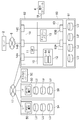
図1は、本実施の形態による記憶システム1の構成を示すものである。この記憶システム1は、サーバ2、仮想化装置3、管理コンソール4及び複数のストレージ装置5A〜5Cから構成される。
(1) Configuration of Storage System According to this Embodiment FIG. 1 shows the configuration of the
上位装置としてのサーバ2は、例えばCPU(Central Processing Unit)やメモリ等の情報処理資源を備えたコンピュータ装置であり、例えばパーソナルコンピュータや、ワークステーション、メインフレームなどから構成される。サーバ2は、例えばキーボード、スイッチやポインティングデバイス、マイクロフォン等の情報入力装置(図示せず)と、例えばモニタディスプレイやスピーカ等の情報出力装置(図示せず)とを備えている。
The
このサーバ2は、例えばSAN、LAN、インターネット、公衆回線又は専用回線などからなる上位側ネットワーク6を介して仮想化装置3と接続される。この上位側ネットワーク6を介したサーバ2及び仮想化装置3間の通信は、例えば上位側ネットワーク6がSANである場合にはファイバチャネルプロトコルに従って行われ、上位側ネットワーク6がLANである場合にはTCP/IP(Transmission Control Protocol/Internet Protocol)プロトコルに従って行われる。
This
仮想化装置3は、サーバに対して、接続された各ストレージ装置5A〜5Cが提供する後述の論理ボリュームLUを仮想化するための処理を行う。この仮想化装置3は、バス10を介して相互に接続されたマイクロプロセッサ11、制御メモリ12、キャッシュメモリ13並びに第1及び第2の外部インタフェース14,15を備える。マイクロプロセッサ11は、1又は複数のCPU(Central Processing Unit)から構成され、制御メモリ12が記憶する制御プログラムに基づいて、例えばサーバ3からストレージ装置5A〜5Cに対するデータ入出力要求が与えられたときに、これに応じたデータ入出力要求をストレージ装置群5内の対応するストレージ装置5A〜5Cに送信するなどの各種処理を実行する。この仮想化装置3は、通信回線に接続されるスイッチ装置の中で提供されることもある。
The
制御メモリ12は、マイクロプロセッサ11のワークエリアとして利用されたり、各種制御プログラムや各種データなどの記憶に用いられる。例えば後述のアドレス変換テーブル20や移行情報テーブル21も、通常はこの制御メモリ12に記憶される。キャッシュメモリ13は、サーバ2及びストレージ装置5A〜5C間のデータ転送時におけるデータの一時的な記憶のために用いられる。
The
第1の外部インタフェース14は、サーバ2との通信時におけるプロトコル制御を行うインタフェースである。第1の外部インタフェース14は、複数のポート14A〜14Cを備えており、いずれかのポート14Bを介して上位側ネットワーク6と接続される。各ポート14A〜14Cには、それぞれを上位側ネットワーク6上において識別するためのWWN(World Wide Name)やIP(Internet Protocol)アドレスなどのネットワークアドレスが付与される。
The first
第2の外部インタフェース15は、仮想化装置3に接続された各ストレージ装置5A,5Bとの通信時におけるプロトコル制御を行うインタフェースである。第2の外部インタフェース15は、第1のインタフェース14と同様に、複数のポート15A,15Bを備えており、いずれかのポート15Aを介して後述の下位側ネットワーク17と接続される。第2の外部インタフェース14の各ポート15A,15Bに対しても下位側ネットワーク17上において識別するためのWWNやIPアドレスなどのネットワークアドレスが付与される。
The second
管理コンソール4は、例えばパーソナルコンピュータ、ワークステーション、あるいは携帯情報端末等のコンピュータから構成され、LAN18を介して仮想化装置と接続されている。この管理コンソール4は、仮想化装置3に対して各種設定を行うためのGUI(Graphical User Interface)や各種情報を表示する表示装置と、オペレータが各種操作や各種設定入力を行うためのキーボードやマウス等の入力装置と、LAN18を介して仮想化装置3と通信を行うための通信装置とを備える。そして管理コンソール4は、入力装置を介して入力された各種指令に基づいて各種処理を実行する。例えば管理コンソール4は、仮想化装置3から必要な情報を収集して表示装置に表示させたり、表示装置に表示したGUIを用いて入力された各種設定事項を仮想化装置に送信する。
The
これらストレージ装置5A〜5Cは、それぞれSAN、LAN、インターネット、公衆回線又は専用回線などからなる下位側ネットワーク17を介して仮想化装置3と接続される。この下位側ネットワーク17を介して行われる仮想化装置3及びストレージ装置5A〜5C間の通信は、例えば下位側ネットワーク17がSANである場合にはファイバチャネルプロトコルに従って行われ、下位側ネットワーク17がLANである場合にはTCP/IPプロトコルに従って行われる。
These
このうちストレージ装置5A,5Bは、例えば図2に示すように、それぞれマイクロプロセッサ20、制御メモリ21、キャッシュメモリ22、複数の第1の外部インタフェース23A〜23C及び複数の第2の外部インタフェース24A,24Bからなるコントロール部25と、複数の記憶デバイス25Aからなる記憶デバイス群26とを備えて構成される。
Of these, as shown in FIG. 2, for example, the
マイクロプロセッサ20は、1又は複数のCPUから構成され、制御メモリ21に格納された制御プログラムに従って各種処理を実行する。制御メモリ21は、例えばマイクロプロセッサ20のワークエリアとして利用されたり、各種制御プログラムや各種データなどの記憶に用いられる。後述するWORM属性テーブルもこの制御メモリ21に記憶される。またキャッシュメモリ22は、仮想化装置3及び記憶デバイス群26間のデータ転送時におけるデータの一時的な記憶のために用いられる。
The
第1の外部インタフェース23A〜23Cは、仮想化装置3との通信時におけるプロトコル制御を行うインタフェースである。これら第1の外部インタフェース23A〜23Cは、それぞれポートを有しており、いずれかの第1の外部インタフェース23A〜23Cがこのポートを介して下位側ネットワーク17と接続される。
The first external interfaces 23 </ b> A to 23 </ b> C are interfaces that perform protocol control during communication with the
第2の外部インタフェースは、記憶デバイスとの通信時におけるプロトコル制御を行うインタフェースである。これら第2の外部インタフェース23A〜23Cは、それぞれポートを有しており、それぞれこのポートを介して記憶デバイス群26の各記憶デバイス26Aと接続される。
The second external interface is an interface that performs protocol control during communication with the storage device. Each of these second
各記憶デバイス26Aは、例えばSCSI(Small Computer System Interface)ディスク等の高価なディスクドライブ、又はSATA(Serial AT Attachment)ディスクや光ディスク等の安価なディスクデバイスから構成される。各記憶デバイス26Aは、冗長性をもたせるため、2本の制御ライン27A,27Bを介してコントロール部25と接続される。
Each
ストレージ装置5A,5Bにおいて、各記憶デバイス26Aはコントロール部25によりRAID方式で運用される。1又は複数の記憶デバイス26Aにより提供される物理的な記憶領域上に、1又は複数の論理的なボリューム(以下、これを論理ボリュームと呼ぶ)LU(図1)が設定される。そしてデータは、この論理ボリュームLUに記憶される。各論理ボリュームLUには、それぞれ固有の識別子(以下、これをLUN(Logical Unit Number)と呼ぶ))が付与される。なお、以下においては、論理ボリュームLUは、論理ユニットと対応してストレージ装置5A〜5Cに管理されるものとする。
In the
図3は、仮想装置3の制御メモリ12に記憶されるアドレス変換テーブル30を示している。図3は、仮想化装置3がサーバ2に提供するある1個の仮想的な論理ボリューム(以下、これを仮想論理ボリュームと呼ぶ)LUに対して仮想化装置3が制御するテーブルの例である。仮想化装置3は、サーバ2に提供する仮想論理ボリュームLUごとにアドレス変換テーブル30を記述しても良いし、アドレス変換テーブル30内で複数の仮想論理ボリュームLUを記述して制御しても良い。
FIG. 3 shows an address conversion table 30 stored in the
この記憶システム1の場合、サーバ2は、データの入出力の対象となる仮想論理ボリュームLUのLUN(以下、これを仮想LUNと呼ぶ)と、入出力すべきデータのデータ長とを指定したデータの入出力要求を、仮想化装置3に送信する。この入出力要求には、仮想論理ボリュームLUの実データを格納するために各ストレージ装置5A〜5Cがそれぞれ提供する記憶領域内のすべてのセクタにそれぞれ付与された通し番号(以下、これを仮想LBA(Logical Block Address)と呼ぶ)のうち、データの入出力の開始位置の仮想LBAも含まれる。仮想化装置3は、アドレス変換テーブル30を用いて、かかるデータ入出力要求に含まれる上述の仮想LUN及び仮想LBAを、実際にデータを読み書きする論理ボリュームLUのLUN及びデータ入出力の開始位置のLBAに変換し、変換後のデータ入出力要求を対応するストレージ装置5A〜5Cに送信する。アドレス変換テーブル30は、このようにホストであるサーバ2が認識している各仮想論理ボリュームLU内のアドレス(仮想LBA)と、現実に実際にデータが入出力される論理ボリュームLUの識別子(LUN)及びアドレス(LBA)とを対応付けたものである。
In the case of this
図3において、「上位側I/F」欄31内の「LBA」欄31Aには、ホストであるサーバ2が認識している仮想LBAが記述される。また「下位側I/F」欄32の「ストレージ名」欄32Aには、その仮想LBAが実際に割り当てられているストレージ装置5A〜5Cのストレージ名がそれぞれ記述され、「LUN」欄32Bには、当該ストレージ装置5A〜5Cが提供する各論理ボリュームLUのLUNがそれぞれ記述され、「LBA」欄32Cには、その論理ボリュームLUの始めのLBAから最後のLBAがそれぞれ記述される。
In FIG. 3, in the “LBA”
従って、この図3の例では、サーバ2が指定する「0〜999」までの仮想LBAは、「A」というストレージ名のストレージ装置5Aが提供するLUNが「0」の論理ボリュームLUに属しており、かかる仮想LBAはその「A」というストレージ装置5AのかかるLUNが「0」の論理ボリュームLUにおける「0〜999」のLBAと対応することが分かる。またサーバ2が指定する「1000〜10399」までの仮想LBAは、「B」というストレージ名のストレージ装置5Bが提供するLUNが「0」の論理ボリュームLUに属しており、かかる仮想LBAはその「B」というストレージ装置5BのかかるLUNが「0」の論理ボリュームLUにおける「0〜399」のLBAと対応することが分かる。
Therefore, in the example of FIG. 3, the virtual LBAs from “0” to “999” specified by the
このように仮想化装置3がサーバ2からのデータ入出力要求に含まれる仮想LUN及び仮想LBAを、実際にデータを入出力すべき論理ボリュームLUのLUN及び実際のデータ入出力の開始位置のLBAに変換して対応するストレージ装置5A〜5Cに送信することで、サーバ2に対して各ストレージ装置5A〜5Cが提供する論理ボリュームLUを仮想化することができ、これにより例えば寿命や故障などの理由によりストレージ装置5A〜5Cの記憶デバイス26Aやストレージ装置5A〜5C全体を交換するに際して、ある一の論理ボリュームLUに格納されたデータを他の論理ボリュームLUに移行した場合においても、ホストであるサーバ2にこれを意識させることなく、サーバ2が所望のデータを交換前と同じ仮想LUNや仮想LBAを指定してそのデータを入出力することができる。
As described above, the
なお、このアドレス変換テーブル30の内容は、管理コンソール4を用いてオペレータにより登録され、仮想化装置3と接続するストレージ装置5A〜5Cを増減したときや、後述のように寿命や故障などの理由によりストレージ装置5A〜5Cの一部の記憶デバイス26A又はストレージ装置5A〜5C全体を交換したときなどに変更される。
Note that the contents of the address conversion table 30 are registered by an operator using the
次に、この記憶システム1において、ストレージ装置5A〜5Cにデータを入出力する場合の動作について説明する。
Next, an operation when data is input / output to / from the
サーバ2は、必要時、対象とする仮想論理ボリュームLUの仮想LUNと、データの開始位置の仮想LBAと、データ長とを指定したストレージ装置5A〜5Cに対するデータ入出力要求を仮想化装置3に送信する。この際サーバ2は、かかるデータ入出力要求が書込み要求である場合には、この書込み要求と共に書込み対象のデータも仮想化装置3に送信する。そしてこの書込み対象のデータは、仮想化装置3のキャッシュメモリ13に一時記憶される。
When necessary, the
仮想化装置3は、サーバ2からのデータ入出力要求を受信すると、このデータ入出力要求に含まれるデータの入出力先アドレスとしての仮想LUN及び仮想LBAを、アドレス変換テーブル30を用いて、実際にデータを入出力する論理ボリュームLUのLUN及び入出力開始位置のLBAにそれぞれ変換し、変換後のデータ入出力要求を対応するストレージ装置に送信する。また仮想化装置3は、かかるサーバ2からのデータ入出力要求が書込み要求である場合には、キャッシュメモリ13に一時記憶している書込み対象のデータを対応するストレージ装置5A〜5Cに送信する。
When receiving the data input / output request from the
ストレージ装置5A〜5Cは、この仮想化装置3からのデータ入出力要求を受信すると、このデータ入出力要求が書込み要求である場合には、この書込み要求と共に送信されるデータを、指定された論理ボリュームLU内の指定されたLBAからブロック単位で書き込む。
When the
またストレージ装置5A〜5Cは、かかる仮想化装置3からのデータ入出力要求が読出し要求である場合には、対応するデータを指定された論理ボリュームLUの指定されたLBAを開始位置としてブロック単位で読み出してキャッシュメモリ22に順次記憶する。そしてストレージ装置5A〜5Cは、このキャッシュメモリ22に記憶したブロック単位のデータを読み出して仮想化装置3に転送する。なおこのデータの転送は、下位側ネットワーク17が例えばSANのときにはブロック単位又はブロック単位で行われ、下位側ネットワーク17が例えばLANのときにはファイル単位で行われる。この後このデータは、仮想化装置3を介してサーバ2に転送される。
Further, when the data input / output request from the
(2)記憶システムにおけるWORM属性情報維持機能
次に、この記憶システム1に搭載されたWORM属性情報維持機能について説明する。この記憶システム1では、ストレージ装置5A〜5Cが提供する、実際にデータを入出力する各論理ボリュームLUごとにWORM属性(WORM設定の有無及び保存期間)を設定することができ、この論理ボリュームLUごとのWORM属性を仮想化装置3が一元管理することを特徴としている。
(2) WORM Attribute Information Maintenance Function in Storage System Next, the WORM attribute information maintenance function installed in the
実際上、図3に示すように、仮想化装置3が保持する上述のアドレス変換テーブル30の「上位側I/F」欄31には、ストレージ装置5A〜5Cが提供する論理ボリュームLUごとに、その論理ボリュームLUのWORM属性を記述するための「WORM属性」欄31Bが設けられている。
In practice, as shown in FIG. 3, the “upper I / F”
この「WORM属性」欄31Bは、「ON/OFF」欄31BX及び「保存期間」欄31BYから構成されており、その論理ボリュームLUにWORM設定(読み出しのみでデータの上書きができない設定)がされている場合には対応する「ON/OFF」欄31BXに「1」、WORM設定がされていない場合にはその「ON/OFF」欄31BXに「0」が記述される。また、その論理ボリュームLUにWORM設定がされている場合には、その論理ボリュームLUに記憶されているデータの保存期間が「保存期間」欄31BYに記述される。なお、この図3では、保存期間を年単位としているが、月単位や週単位、日単位又は時間単位で設定できるようにしてもよい。
The “WORM attribute”
そして仮想化装置3は、サーバ2からストレージ装置5A〜5Cに対するデータ入出力要求としてデータを上書きするようなデータ書込み要求が与えられたときには、アドレス変換テーブル30を参照して、対象とする論理ボリュームLUにWORM設定がされているか否か(対応する「WORM属性」欄31Bの「ON/OFF」欄31BXに「1」が記述されているか否か)を判定する。そして仮想化装置3は、WORM設定がされていないときにはそのデータ書込み要求を受け入れ、WORM設定がされているときにはそのデータ書込み要求を拒否する旨をサーバ2に通知する。
When the
一方、仮想化装置3は、ある論理ボリュームLUに記憶されたデータを他の論理ボリュームLUに移行させる場合における移行元の論理ボリューム(以下、これを移行元論理ボリュームと呼ぶ)LUの位置(と、移行先の論理ボリューム(以下、これを移行先論理ボリュームと呼ぶ)LUの位置とを対応付ける図4に示すような移行情報テーブル40を制御メモリ12(図1)内に有している。
On the other hand, the
そして仮想化装置3には、例えばストレージ装置5A〜5Cの記憶デバイス26Aやストレージ装置5A〜5C自体を交換するに際して、ある論理ボリュームLUのデータを他の論理ボリュームLUに移行するような場合に、オペレータの操作により管理コンソール4(図1)から移行元論理ボリュームLUを有するストレージ装置5A〜5Cのストレージ名及びその移行元論理ボリュームLUのLUNと、移行先論理ボリュームLUを有するストレージ装置5A〜5Cのストレージ名及びその移行先論理ボリュームのLUNとが与えられる。なお、ここではストレージ装置5A〜5Cの名を記憶するが、ストレージ装置5A〜5Cを一義的に識別可能なものであれば、どのようなものを用いても良い。
For example, when the
この結果、これら移行元論理ボリュームLUを有するストレージ装置5A〜5Cのストレージ名及びその移行元論理ボリュームのLUNがそれぞれ移行情報テーブル40の「移行元アドレス」欄41内の「ストレージ名」欄41A及び「LUN」欄41Bに記述され、移行先論理ボリュームLUを有するストレージ装置5A〜5Cのストレージ名及びその移行先論理ボリュームLUのLUNがそれぞれ移行情報テーブル40の「移行先アドレス」欄42内の「ストレージ名」欄42A及び「LUN」欄42Bに記述される。
As a result, the storage names of the
そして仮想化装置3は、図5に示すように、この後移行情報テーブル40に登録された移行元論理ボリュームLUから移行先論理ボリュームLUへのデータの移行が開始されると、この移行情報テーブル40とアドレス変換テーブル30(図3)とに基づいて、アドレス変換テーブル30の「下側I/F」欄31における移行元論理ボリュームLUの「ストレージ名」欄32A及び「LUN」欄32Bの各内容を、移行情報テーブル40における移行先論理ボリュームLUの「ストレージ名」欄42A及び「LUN」欄42Bの内容に変更した図6に示すような新たなアドレス変換テーブル30を生成し、かかるデータ移行の完了後にはアドレス変換テーブル30を切り替えて、この新たなアドレス変換テーブル30を用いてストレージ装置5A〜5Cの仮想化処理を実行するようになされている。
Then, as shown in FIG. 5, the
この場合において、この新たなアドレス変換テーブル30は、上述のように「WORM属性情報」欄31Bの内容をいじることなく、「下位側I/F」の「ストレージ名」及び「LUN」のみを変更して生成されるために、そのデータを記憶していた移行元の論理ボリュームLUに設定されたWORM属性が正確に移行先の論理ボリュームLUに引き継がれることとなる。よって、一の論理ボリュームLUに記憶されているデータを他の論理ボリュームLUに移行させた場合における、そのデータに関するWORM属性の設定ミスや悪意による改変を確実に防止して、WORMによりガードすべきデータの改ざんや消失といった事故を未然に防止することができる。
In this case, the new address conversion table 30 changes only the “storage name” and “LUN” of the “lower I / F” without changing the contents of the “WORM attribute information”
なお、この記憶システム1では、各ストレージ装置5A〜5Cが、それぞれ仮想化装置3から所定のタイミングで与えられる、そのストレージ装置5A〜5Cが有する各論理ボリュームLUのWORM属性情報のみを抽出したWORM属性情報テーブル50を制御メモリ21(図2)に記憶保持するようになされている。各ストレージ装置5A〜5CがこのWORM属性情報テーブル50に従い、自身が有する論理ボリュームLUへの入出力制限を行うことで、仮想化装置3では制御し得ない下位側ネットワーク17への不正接続や、下位側ネットワーク17に接続されるイニシエータのエラーによるWORM設定された論理ボリュームLUに格納されたデータの不正更新を防ぐことができる。このように、これら各ストレージ装置5A〜5Cに記憶保持されたWORM属性情報テーブル50に基づいて、仮想化装置3を交換する場合においても、WORM属性情報を正確に維持できる。
In this
ここで図7は、このようなWORM属性情報維持機能に関する一連の処理の流れを示すタイミングチャートである。まずストレージ装置5A〜5Cが提供する各論理ボリュームLUに対するWORMの初期設定について説明する。かかる論理ボリュームLUに対するWORMの初期設定は、管理コンソール4を操作して仮想化装置3の制御メモリ12に記憶されたアドレス変換テーブル30の「WORM属性」欄31Bのうちの「ON/OFF」欄31BXに格納されるパラメータ値(0又は1)を指定することにより行う(SP1)。ただし、この時点での設定内容は未だ保留状態である。
Here, FIG. 7 is a timing chart showing a flow of a series of processes regarding such a WORM attribute information maintenance function. First, the initial setting of WORM for each logical volume LU provided by the
この後この設定に基づいて、仮想化装置3は、対応するストレージ装置5A〜5Cに対して対応する論理ボリュームLUをWORM設定すべき旨のガードコマンドを送信する(SP2)。ストレージ装置5A〜5Cは、このガードコマンドに基づいて、その論理ボリュームLUに対してWORM設定を行う。そしてストレージ装置5A〜5Cは、かかるWORM設定をした後に、その旨を仮想化装置3に通知する(SP3)。この段階で、仮想化装置3において、アドレス変換テーブル30における「WORM属性」欄31Bの「ON/OFF」欄31BXに格納されたパラメータが確定する。この後仮想化装置3は、このパラメータが確定したことを管理コンソール4に通知する(SP4)。
Thereafter, based on this setting, the
次に、仮想化装置3に接続されたストレージ装置5A〜5Cの記憶デバイス26Aを交換する場合について説明する。以下においては、図6のように、仮想化装置3に接続されたストレージ装置5Bが有するLUNが「a」の論理ボリュームLUに記憶されているWORM設定されたデータを、ストレージ装置5Cが有するLUNが「a´」の論理ボリュームLUにWORM属性情報を伴って移行させるものとする。
Next, a case where the
まずオペレータは、管理コンソール4に、移行対象のデータが存在するストレージ装置5Bのストレージ名及び論理ボリュームLUのLUN(「a」)を設定入力する。移行先のストレージ装置5Cのストレージ名及び論理ボリュームLUのLUN(「a´」)についても同様に管理コンソール4に設定入力する。そしてこの設定入力された情報が管理コンソール4から仮想化装置3に通知される(SP5)。また仮想化装置3は、この通知に基づいて、必要な情報を移行情報テーブル40の対応する欄に順次格納することによって、実際の移行情報テーブル40を生成する(SP6)。移行先論理ボリュームLUについては、このとき予約ロックされ、この後データ移行が完了するまではその他の用途には使用できない状態になる。
First, the operator sets and inputs to the
この後、オペレータからデータの移行開始指令が管理コンソール4に入力されると、これに応じたコマンド(以下、これを移行開始コマンドと呼ぶ)が仮想化装置3に与えられる(SP7)。このとき仮想化装置3は、そのときのアドレス変換テーブル30(以下、これを旧アドレス変換テーブルと呼ぶ)及び移行情報テーブル40に基づいて上述のようにして新たなアドレス変換テーブル(以下、これを新アドレス変換テーブルと呼ぶ)を生成する。従って、この新アドレス変換テーブル30では、そのデータに関するWORM属性情報が維持される。ただし、この時点では、新アドレス変換テーブル30はサスペンド状態で保持される。
Thereafter, when a data migration start command is input from the operator to the
また仮想化装置3は、かかる移行開始コマンドが管理コンソール4から与えられると、対応するストレージ装置5B,5Cを制御して、ストレージ装置5B,5Cのリモートコピー機能を利用したデータの移行を実行させる。ここで、リモートコピー機能とは、ストレージ装置5A〜5C間において、論理ボリュームLU単位である論理ボリュームLU(以下、適宜、これを正ボリュームと呼ぶ)の内容を、他の論理ボリュームLU(以下、適宜、これを副ボリュームと呼ぶ)にコピー(複写)する機能をいう。リモートコピーでは、通常、正ボリューム及び副ボリュームを対応付けるペア設定を行った後に正ボリュームから副ボリュームへのデータ移行を開始する。なお、リモートコピー機能については、特開2002-189570号公報において詳しく説明されている。
Further, when the migration start command is given from the
仮想化装置3は、このようなリモートコピー機能により正ボリュームから副ボリュームにデータを移行させるため、まず移行情報テーブル40を参照して、移行元論理ボリュームLU(LUNが「a」の論理ボリュームLU)を提供するストレージ装置5Bにコマンドを送信することにより当該移行元論理ボリュームLUをリモートコピーの正ボリュームに設定する(SP8)。また仮想化装置3は、これと併せて移行先論理ボリュームLU(LUNが「a´」の論理ボリュームLU)を提供するストレージ装置5Cにコマンドを送信することにより当該移行先論理ボリュームLUをリモートコピーの副ボリュームに設定する(SP9)。そして仮想化装置3は、このように移行元論理ボリュームLU及び移行先論理ボリュームLUをそれぞれリモートコピーの正ボリューム及び副ボリュームとしてペア設定し終えると、その旨を管理コンソール4に通知する(SP10)。
In order to migrate data from the primary volume to the secondary volume by using such a remote copy function, the
管理コンソール4は、この通知を受信すると、その後仮想化装置3に対してリモートコピーを開始すべき旨のコマンドを送信し(SP11)、仮想化装置3は、このコマンドを受信すると、正ボリューム側のストレージ装置5Bに開始指令を送信する(SP12)。かくしてこの開始指令に応動して、正ボリューム側のストレージ装置5B及び副ボリューム側のストレージ装置5C間において対象とするデータの移行が実行される(SP13)。
Upon receiving this notification, the
そしてこのデータの移行が完了すると、正ボリューム側のストレージ装置5Bから副ボリューム側のストレージ装置5Cに対して移行したデータをWORMによりガードすべき旨の通知がなされる(SP14)。また副ボリューム側のストレージ装置5Cでは、この通知に従って、かかる副ボリュームのWORM属性がWORM属性情報テーブル50に登録され(すなわちWORM属性情報テーブル50において、副ボリュームにWORM設定がなされ)、この後その旨が副ボリューム側のストレージ装置5Cから正ボリューム側のストレージ装置5Bに通知される(SP15)。
When this data migration is completed, a notification is sent that the migrated data should be guarded by WORM from the primary
ここで、通常のリモートコピーにおいて、正ボリュームへの更新が続いている場合には、ストレージ装置5A〜5Cがデータ移行中の正ボリュームの更新内容を監視し、正ボリューム及び副ボリュームが完全に同じ内容になるまでデータ移行が行われる。しなしながら、正ボリュームにWORM設定がされているときには、データの更新がなされず、従って、正ボリュームのデータを副ボリュームに移行し終えた段階でペア設定を解除できる。
Here, in the normal remote copy, when the update to the primary volume continues, the
そこで、正ボリューム側のストレージ装置5Bは、この通知を受信すると、正ボリューム及び副ボリュームのペア設定を解除した後、副ボリュームにWORM設定がなされた旨の通知を仮想化装置3に通知する(SP16)。また仮想化装置3は、この副ボリュームにWORM設定がなされた旨の通知を受信すると、アドレス変換テーブル30を新アドレス変換テーブル30に切り替えてこの新アドレス変換テーブル30を活性化させ(SP17)、さらにこの後データの移行が完了した旨を管理コンソール4に通知する(SP18)。
Accordingly, when the
ここで、一般的にリモートコピー処理では、副ボリュームは、リモートコピーを行っている最中は正ボリュームからのデータがコピーされている状態でありホストからの更新はなされない。コピーが完了し、ペア設定が解除されると、副ボリュームはホストからの更新等のアクセスが可能となる。本実施の形態では、データ移行が完了してから副ボリュームのWORM属性情報テーブル50に更新ガード設定がなされ、その後ペア設定が解除される。 Here, in general, in remote copy processing, the secondary volume is in a state where data from the primary volume is being copied during remote copy and is not updated from the host. When the copying is completed and the pair setting is released, the secondary volume can be accessed from the host such as update. In the present embodiment, after the data migration is completed, the update guard setting is made in the WORM attribute information table 50 of the secondary volume, and then the pair setting is released.
これは、データの移行前に副ボリュームに更新ガードをかけると、該副ボリュームに書き込みができない為データの移行ができず、さらに、ペア設定解除の後で、更新ガードが設定されると、ペア設定解除と更新ガード設定のなされる間に下位側ネットワーク17から副ボリュームへの不正更新がなされるおそれがあるためである。このように本実施の形態では副ボリュームへの下位側ネットワーク17からの不正アクセスを防ぎ、リモートコピー処理を実行することができる。なお、ペア設定中には、例えば、正ボリューム側のストレージ装置5Bからのみ、更新ガード設定要求を受け付けるなど、送信元の装置によって更新ガード設定要求を受け付けるか否かを決定可能にすれば、不正な送信元からの更新ガード設定要求によってデータ移行が妨げられる事態を回避することが可能になる。
This is because if an update guard is applied to a secondary volume before data migration, data cannot be migrated because data cannot be written to the secondary volume, and if update guard is set after pair setting cancellation, This is because an unauthorized update from the
因みに、仮想化装置3は、上述のようなデータ移行の一連の処理の中で、例えばリモートコピーを行わせる場合の正ボリューム及び副ボリュームの同期が失敗したときや、副ボリューム側のストレージ装置5Cにおいて移行されたデータに対するWORM切り替えに失敗したときなどには、データ移行が失敗した旨を管理コンソール4に通知する。この結果、このデータ移行処理がエラーで終了し、仮想化装置3におけるアドレス変換テーブル30の切り替えは行われない。
Incidentally, the
一方、図8は、データの移行処理中にサーバ2からそのデータに対するデータ読出し要求が与えられた場合の一連の処理の流れを示すタイミングチャートである。この場合、仮想化装置3は、サーバ2からかかるデータ読出し要求が与えられたときに(SP20)、アドレス変換テーブル30が未だ新アドレス変換テーブル30に切り替えられていない場合には、旧アドレス変換テーブル30に基づいて、データ読出し要求に含まれる対象とする論理ボリュームLUのLUN及び入出力開始位置の仮想LBAを正ボリューム(移行元論理ボリュームLU)側のLUN及びLBAにそれぞれ変換した後にこれを当該正ボリュームを有するストレージ装置5Bに送信することにより(SP21)、指定されたデータを正ボリュームから読み出させて(SP22)、これをサーバ2に転送する(SP23)。
On the other hand, FIG. 8 is a timing chart showing a flow of a series of processes when a data read request for the data is given from the
これに対して仮想化装置3は、サーバ2からかかるデータ読出し要求が与えられたときに(SP24)、アドレス変換テーブル30が新アドレス変換テーブル30に切り替えられている場合には、この新アドレス変換テーブル30に基づいて、データ読出し要求に含まれる対象とする論理ボリュームLUのLUN及び入出力開始の仮想LBAを副ボリューム(移行先論理ボリュームLU)側のLUN及びLBAにそれぞれ変換し、これを当該副ボリュームを有するストレージ装置5Cに送信することにより(SP25)、指定されたデータを副ボリュームから読み出させて(SP26)、これをサーバ2に転送する(SP27)。
On the other hand, when the
他方、図9は、データの移行処理中にサーバ2からそのデータに対するデータ書込み要求が与えられた場合の一連の処理の流れを示すタイミングチャートである。この場合、仮想化装置3は、サーバ2からかかるデータ書込み要求が与えられたときに(SP30)、アドレス変換テーブル30を参照し、そのデータが記憶された論理ボリュームLUに対する「WORM属性」欄31Bの「ON/OFF」欄31BXに「1」が記述されていることを確認すると、データ書込み要求を拒否する旨の通知をサーバ2に通知する。
On the other hand, FIG. 9 is a timing chart showing a flow of a series of processes when a data write request for the data is given from the
以上のように、この記憶システム1では、サーバ2及び各ストレージ装置5A〜5C間に、サーバ2に対して各ストレージ装置5A〜5Cが提供する各論理ボリュームLUを仮想化する仮想化装置3が配置されているため、ストレージ装置5A〜5Cの記憶デバイス26Aやストレージ装置5A〜5C全体を交換するに際して、一の論理ボリュームLUに格納されたデータを他の論理ボリュームLUに移行した場合においても、ホストであるサーバ2にこれを意識させることなく、サーバ2が所望のデータを交換前と同じ論理ボリュームLUを指定してそのデータを入出力するようにすることができる。
As described above, in this
またこの仮想化装置3が、各ストレージ装置5A〜5Cが提供する各論理ボリュームLUのWORM属性をも一元管理し、一の論理ボリュームLUに記憶されたデータが他の論理ボリュームLUに移行されたときには、元のアドレス変換テーブル30及び移行情報テーブル40を用いて、移行先の論理ボリュームLUのWORM属性を移行先の論理ボリュームLUに引き継ぐように、新たなアドレス変換テーブル30を生成するようにしているため、そのデータに関するWORM属性の設定ミスや悪意による改変を確実に防止して、WORMにより保護されるべきデータの改ざん又は消失を未然に防止することができる。
The
このように本実施の形態による記憶システム1は、WORM設定により保護されるべきデータの改変又は消失を未然に防止して記憶システムの信頼性を向上させることができ、またストレージ装置や記憶デバイスの交換の前後でホスト装置から見た論理ボリュームの属性が変化することに起因する不具合を防止して、より一層と高い信頼性を得ることができる。
As described above, the
(3)他の実施の形態
なお上述の実施の形態においては、本発明を、WORM設定を論理ボリュームLU単位で設定できる記憶システム1に適用する場合について述べたが、本発明はこれに限らず、WORM設定できる単位がストレージ装置5A〜5C単位(すなわち1つのストレージ装置5A〜5Cが提供する全記憶領域を単位とする)である記憶システムや、論理ボリュームLU以外の記憶領域の単位をWORM設定できる単位とする記憶システムにも広く適用することができる。
(3) Other Embodiments In the above-described embodiment, the case where the present invention is applied to the
また上述の実施の形態においては、データ移行を行ったときに移行元の論理ボリュームLUに設定されたWORM属性を移行先の論理ボリュームLUに引き継がせるようにした場合について述べたが、本発明はこれに限らず、例えばデータ移行元の論理ボリュームLUに設定されている他の入出力制限(例えばデータの読み出しを禁止する制限や他の制限)についてもこれと同様に移行元の論理ボリュームLUの設定を移行先の論理ボリュームLUに引き継がせることができる。 In the above-described embodiment, the case has been described in which the WORM attribute set in the migration source logical volume LU is transferred to the migration destination logical volume LU when data migration is performed. Not limited to this, for example, other input / output restrictions set in the data migration source logical volume LU (for example, restrictions prohibiting reading of data and other restrictions) are similarly applied to the migration source logical volume LU. The settings can be transferred to the migration destination logical volume LU.
さらに上述の実施の形態においては、仮想装置3において、論理ボリュームLUごとに設定されるWORM属性を一元管理する入出力管理部を、マイクロプロセッサ11及び制御メモリ12により構成するようにした場合について述べたが、本発明はこれに限らず、この他種々の構成を広く適用することができる。
Further, in the above-described embodiment, a description will be given of a case where the input / output management unit that centrally manages the WORM attribute set for each logical volume LU is configured by the
さらに上述の実施の形態においては、仮想装置3が記憶デバイスを有しない構成とするようにした場合について述べたが、本発明はこれに限らず、例えば図1との対応部分に同一符号を付した図10に示すように、仮想化装置60が1又は複数の記憶デバイス61を有する構成とするようにしても良い。この図10は、図1の仮想化装置3とほぼ同様に構成されたコントロール部62が、ディスクインタフェース部63の各ポート63A,63Bを介して各記憶デバイス61と接続されると共に、第1の外部インタフェース部14のいずれかのポート14Aを介して下位側ネットワーク17と接続された構成例を示したものである。なお、このように仮想化装置60を構築する場合には、サーバ2に対して当該仮想化装置60が提供する論理ボリュームLUをも仮想化等するために、これら論理ボリュームLUについてストレージ装置5A〜5Cの論理ボリュームLUと同様にアドレス変換テーブル64にLUNやWORM属性等の情報を登録する必要がある。
Furthermore, in the above-described embodiment, the case where the
さらに上述の実施の形態においては、仮想化装置3が、論理ボリュームLUごとに設定されるWORM設定を一元管理し、一の論理ボリュームLUに記憶されたデータが他の論理ボリュームLUに移行されたときには、移行前の論理ボリュームLUに設定されたWORM設定を移行後の論理ボリュームLUに設定するようにした場合について述べたが、本発明はこれに限らず、例えば、仮想化装置3においてデータごとにWORM設定できるように仮想化装置3を構築し、一の論理ボリュームLUに記憶されたデータが他の論理ボリュームLUに移行されたときには、移行前のデータに設定されたWORM設定を移行後のデータに設定するように仮想化装置3を構築するようにしても良い。
Further, in the above-described embodiment, the
本発明は、例えばアーカイブデータを長期間保存するような記憶システムのほか、種々の形態の記憶システムに広く適用することができる。 The present invention can be widely applied to various forms of storage systems in addition to storage systems that store archive data for a long period of time, for example.
1……記憶システム、2……サーバ、3,62……仮想化装置、4……管理コンソール、5A〜5C……ストレージ装置、11,20……マイクロプロセッサ、12,21……制御メモリ、26A,61……記憶デバイス、30,64……アドレス変換テーブル、40……移行情報テーブル、LU……論理ボリューム。
DESCRIPTION OF
Claims (18)
上位装置に対して各前記記憶領域を仮想化する仮想化装置と
を備え、
前記仮想化装置は、前記記憶領域ごと又は前記記憶領域に記憶されるデータごとに設定されるデータの入出力制限を一元管理し、一の前記記憶領域に記憶された前記データが他の前記記憶領域に移行されたときには、移行前の前記記憶領域又は前記データに設定された前記入出力制限を移行後の前記記憶領域又は前記データに設定する
ことを特徴とする記憶システム。 One or more storage devices each having one or more storage areas;
A virtualization device that virtualizes each storage area with respect to a host device,
The virtualization apparatus centrally manages input / output restrictions on data set for each storage area or for each data stored in the storage area, and the data stored in one storage area is stored in another storage The storage system is characterized in that, when migrated to an area, the input / output restriction set in the storage area or data before migration is set in the storage area or data after migration.
前記データの読み出しのみを可能とする制限である
ことを特徴とする請求項1に記載の記憶システム。 The input / output restrictions are:
The storage system according to claim 1, wherein the storage system is a restriction that allows only reading of the data.
前記データの保存期間を含む
ことを特徴とする請求項2に記載の記憶システム。 The input / output restrictions are:
The storage system according to claim 2, further comprising a storage period of the data.
前記上位装置が認識する前記記憶領域の仮想的なアドレスと、各前記記憶領域の現実のアドレスと、前記記憶領域に対する前記入出力制限の設定内容とをそれぞれ対応付けたアドレス変換テーブルを有し、当該アドレス変換テーブルを用いて前記上位装置からのデータ入出力要求のアドレスを変換するようにして、前記上位装置に対して各前記記憶領域を仮想化し、
前記一の記憶領域に記憶された前記データが前記他の記憶領域に移行されるときに、前記アドレス変換テーブルの当該一の記憶領域のアドレスを前記他の記憶領域のアドレスに変更した新たな前記アドレス変換テーブルを生成し、前記アドレス変換テーブルを当該新たなアドレス変換テーブルに切り替えるようにして、移行前の前記記憶領域に設定された前記入出力制限を移行後の前記記憶領域に設定する
ことを特徴とする請求項1に記載の記憶システム。 The virtualization device is
An address conversion table associating the virtual address of the storage area recognized by the host device, the actual address of each storage area, and the setting contents of the input / output restriction for the storage area; By using the address conversion table to convert the address of the data input / output request from the host device, each storage area is virtualized for the host device,
When the data stored in the one storage area is transferred to the other storage area, the address of the one storage area of the address conversion table is changed to the address of the other storage area. Generating an address translation table, switching the address translation table to the new address translation table, and setting the input / output restriction set in the storage area before migration to the storage area after migration. The storage system according to claim 1, characterized in that:
前記管理装置は、設定入力された前記一の記憶領域及び前記他の記憶領域を前記仮想化装置に通知し、
前記仮想化装置は、
前記管理装置からの前記通知に応じて、前記一の記憶領域及び前記他の記憶領域を対応付けた移行情報テーブルを生成し、
当該生成した前記移行情報テーブルと、元の前記アドレス変換テーブルとに基づいて、前記新たなアドレス変換テーブルを生成する
ことを特徴とする請求項4に記載の記憶システム。 A management device for an operator to set and input the one storage area and the other storage area;
The management device notifies the virtualization device of the one storage area and the other storage area that have been set and input,
The virtualization device is
In response to the notification from the management device, generate a migration information table that associates the one storage area with the other storage area,
The storage system according to claim 4, wherein the new address conversion table is generated based on the generated migration information table and the original address conversion table.
上位装置に対して各前記記憶領域を仮想化する仮想化装置を設け、当該仮想化装置により前記記憶領域ごと又は前記記憶領域に記憶されるデータごとに設定されるデータの入出力制限を一元管理する第1のステップと、
一の前記記憶領域に記憶された前記データが他の前記記憶領域に移行されたときに、前記仮想化装置において、移行前の前記記憶領域又は前記データに設定された前記入出力制限を移行後の前記記憶領域又は前記データに設定する第2のステップと
を備えることを特徴とする記憶システムの制御方法。 In a control method of a storage system having one or more storage devices each having one or more storage areas,
A virtualization device that virtualizes each storage area for a host device is provided, and centralized management of data input / output restrictions set for each storage area or each data stored in the storage area by the virtualization device A first step to:
When the data stored in one storage area is migrated to another storage area, the virtualization device has migrated the I / O restriction set in the storage area or data before migration. And a second step of setting the data in the storage area or the data.
前記データの読み出しのみを可能とする制限である
ことを特徴とする請求項6に記載の記憶システムの制御方法。 The input / output restrictions are:
The storage system control method according to claim 6, wherein the restriction is such that only reading of the data is possible.
前記データの保存期間を含む
ことを特徴とする請求項7に記載の記憶システムの制御方法。 The input / output restrictions are:
The storage system control method according to claim 7, further comprising a retention period of the data.
前記上位装置が認識する前記記憶領域の仮想的なアドレスと、各前記記憶領域の現実のアドレスと、前記記憶領域に対する前記入出力制限の設定内容とをそれぞれ対応付けたアドレス変換テーブルを有し、
前記第1のステップでは、
前記仮想化装置が、当該アドレス変換テーブルを用いて前記上位装置からのデータ入出力要求のアドレスを変換するようにして、前記上位装置に対して各前記記憶領域を仮想化し、
前記第2のステップでは、
前記仮想化装置は、前記一の記憶領域に記憶された前記データが前記他の記憶領域に移行されるときに、前記アドレス変換テーブルの当該一の記憶領域のアドレスを前記他の記憶領域のアドレスに変更した新たな前記アドレス変換テーブルを生成し、前記アドレス変換テーブルを当該新たなアドレス変換テーブルに切り替えるようにして、移行前の前記記憶領域に設定された前記入出力制限を移行後の前記記憶領域に設定する
ことを特徴とする請求項6に記載の記憶システムの制御方法。 The virtualization device is
An address conversion table associating the virtual address of the storage area recognized by the host device, the actual address of each storage area, and the setting contents of the input / output restriction for the storage area;
In the first step,
The virtualization device converts the address of the data input / output request from the host device using the address conversion table, virtualizes each storage area for the host device,
In the second step,
When the data stored in the one storage area is migrated to the other storage area, the virtualization apparatus sets the address of the one storage area of the address conversion table to the address of the other storage area. The new address conversion table changed to the above is generated, the address conversion table is switched to the new address conversion table, and the input / output restriction set in the storage area before the transfer is changed to the storage after the transfer. The storage system control method according to claim 6, wherein the storage system is set to an area.
前記第2のステップでは、
前記管理装置が、設定入力された前記一の記憶領域及び前記他の記憶領域を前記仮想化装置に通知し、
前記仮想化装置が、前記管理装置からの前記通知に応じて、前記一の記憶領域及び前記他の記憶領域を対応付けた移行情報テーブルを生成し、当該生成した前記移行情報テーブルと、元の前記アドレス変換テーブルとに基づいて、前記新たなアドレス変換テーブルを生成する
ことを特徴とする請求項9に記載の記憶システムの制御方法。 The storage system includes a management device for an operator to set and input the one storage area and the other storage area,
In the second step,
The management device notifies the virtualization device of the one storage area and the other storage area that have been set and input,
In response to the notification from the management apparatus, the virtualization apparatus generates a migration information table in which the one storage area and the other storage area are associated with each other. The storage system control method according to claim 9, wherein the new address conversion table is generated based on the address conversion table.
前記記憶領域ごと又は前記記憶領域に記憶されるデータごとに設定されるデータの入出力制限を一元管理する入出力制限管理部
を備え、
前記入出力制限管理部は、
一の前記記憶領域に記憶された前記データが他の前記記憶領域に移行されたときに、移行前の前記記憶領域又はデータに設定された前記入出力制限を移行後の前記記憶領域又は前記データに設定する
ことを特徴とする仮想化装置。 In a virtualization apparatus that virtualizes each storage area of one or a plurality of storage apparatuses each having one or a plurality of storage areas with respect to a host apparatus,
An input / output restriction management unit that centrally manages the input / output restrictions of data set for each storage area or for each data stored in the storage area,
The input / output restriction management unit
When the data stored in one storage area is transferred to another storage area, the storage area or the data after the input / output restriction set in the storage area or data before the transfer is transferred A virtualization device characterized by being set to
前記データの読み出しのみを可能とする制限である
ことを特徴とする請求項11に記載の仮想化装置。 The input / output restrictions are:
The virtualization apparatus according to claim 11, wherein the restriction is such that only reading of the data is possible.
前記データの保存期間を含む
ことを特徴とする請求項12に記載の仮想化装置。 The input / output restrictions are:
The virtualization apparatus according to claim 12, further comprising a storage period of the data.
前記上位装置が認識する前記記憶領域の仮想的なアドレスと、各前記記憶領域の現実のアドレスと、前記記憶領域に対する前記入出力制限の設定内容とをそれぞれ対応付けたアドレス変換テーブルを記憶するメモリ
を備え、
前記入出力管理制限部は、
当該アドレス変換テーブルを用いて前記上位装置からのデータ入出力要求のアドレスを変換するようにして、前記上位装置に対して各前記記憶領域を仮想化し、前記一の記憶領域に記憶された前記データが前記他の記憶領域に移行されるときに、前記アドレス変換テーブルの当該一の記憶領域のアドレスを前記他の記憶領域のアドレスに変更した新たな前記アドレス変換テーブルを生成し、前記アドレス変換テーブルを当該新たなアドレス変換テーブルに切り替えるようにして、移行前の前記記憶領域に設定された前記入出力制限を移行後の前記記憶領域に設定する
ことを特徴とする請求項11に記載の仮想化装置。 The input / output restriction management unit
Memory that stores an address conversion table in which the virtual address of the storage area recognized by the host device, the actual address of each storage area, and the setting contents of the input / output restriction for the storage area are associated with each other With
The input / output management restriction unit includes:
The data stored in the one storage area is virtualized by converting each storage area for the host apparatus by converting the address of the data input / output request from the host apparatus using the address conversion table. Is transferred to the other storage area, the address conversion table is generated by changing the address of the one storage area of the address conversion table to the address of the other storage area, and the address conversion table The virtualization according to claim 11, wherein the I / O restriction set in the storage area before migration is set in the storage area after migration by switching to the new address conversion table. apparatus.
外部装置から通知される、オペレータにより設定入力された前記一の記憶領域及び前記他の記憶領域を対応付けた移行情報テーブルを生成し、
当該生成した前記移行情報テーブルと、元の前記アドレス変換テーブルとに基づいて、前記新たなアドレス変換テーブルを生成する
ことを特徴とする請求項14に記載の仮想化装置。 The input / output restriction management unit
Generate a migration information table that is associated with the one storage area and the other storage area that are set and input by an operator, notified from an external device,
The virtualization apparatus according to claim 14, wherein the new address conversion table is generated based on the generated migration information table and the original address conversion table.
上位装置に対して各前記記憶領域を仮想化し、仮想記憶領域として提供する仮想化装置と
を備え、
前記仮想化装置は、前記仮想記憶領域に対するデータの保存期間を含む入出力制限の設定を、前記仮想記憶領域を構成する前記記憶領域ごとに一元管理し、一の前記記憶領域に記憶された前記データが他の前記記憶領域に移行されたときに、移行前の前記記憶領域に対する前記入出力制限を、移行後の前記記憶領域に対する入出力制限の設定として管理する
ことを特徴とする記憶システム。 One or more storage devices each having one or more storage areas;
A virtualization device that virtualizes each storage area to a host device and provides it as a virtual storage area,
The virtualization apparatus centrally manages the setting of the input / output restriction including the data storage period for the virtual storage area for each of the storage areas constituting the virtual storage area, and is stored in the one storage area When the data is migrated to another storage area, the input / output restriction for the storage area before the migration is managed as an input / output restriction setting for the storage area after the migration.
上位装置に対して各前記記憶領域を仮想化し、仮想化記憶領域として提供する仮想化装置を設け、当該仮想化装置により、前記仮想記憶領域に対するデータの保存期間を含む入出力制限の設定を、前記仮想記憶領域を構成する前記記憶領域ごとに一元管理する第1のステップと、
一の前記記憶領域に記憶された前記データが他の前記記憶領域に移行されたときに、移行前の前記記憶領域に対する前記入出力制限を、移行後の前記記憶領域に対する入出力制限の設定として管理する第2のステップと
を備えることを特徴とする記憶システムの制御方法。 In a control method of a storage system having one or more storage devices each having one or more storage areas,
A virtualization device that virtualizes each storage area with respect to a host device and provides it as a virtual storage region is provided. A first step of centrally managing each storage area constituting the virtual storage area;
When the data stored in one storage area is migrated to another storage area, the input / output restriction for the storage area before migration is set as the input / output restriction for the storage area after migration. And a second step of managing the storage system.
前記仮想記憶領域に対するデータの保存期間を含む入出力制限の設定を、前記仮想記憶領域を構成する前記記憶領域ごとに一元管理する入出力制限管理部
を備え、
前記入出力制限管理部は、
一の前記記憶領域に記憶された前記データが他の前記記憶領域に移行されたときに、移行前の前記記憶領域に対する前記入出力制限を、移行後の前記記憶領域に対する入出力制限の設定として管理する
ことを特徴とする仮想化装置。 In a virtualization apparatus that virtualizes each storage area of one or a plurality of storage apparatuses each having one or a plurality of storage areas, and provides the host apparatus as a virtual storage area,
An input / output restriction management unit that centrally manages the setting of the input / output restriction including the data storage period for the virtual storage area for each of the storage areas constituting the virtual storage area,
The input / output restriction management unit
When the data stored in one storage area is migrated to another storage area, the input / output restriction for the storage area before migration is set as the input / output restriction for the storage area after migration. A virtualization device characterized by management.
Priority Applications (2)
| Application Number | Priority Date | Filing Date | Title |
|---|---|---|---|
| JP2005017210A JP2006209237A (en) | 2005-01-25 | 2005-01-25 | Storage system, control method therefor, and virtualization apparatus |
| US11/101,511 US20060168415A1 (en) | 2005-01-25 | 2005-04-08 | Storage system, controlling method thereof, and virtualizing apparatus |
Applications Claiming Priority (1)
| Application Number | Priority Date | Filing Date | Title |
|---|---|---|---|
| JP2005017210A JP2006209237A (en) | 2005-01-25 | 2005-01-25 | Storage system, control method therefor, and virtualization apparatus |
Publications (1)
| Publication Number | Publication Date |
|---|---|
| JP2006209237A true JP2006209237A (en) | 2006-08-10 |
Family
ID=36698435
Family Applications (1)
| Application Number | Title | Priority Date | Filing Date |
|---|---|---|---|
| JP2005017210A Pending JP2006209237A (en) | 2005-01-25 | 2005-01-25 | Storage system, control method therefor, and virtualization apparatus |
Country Status (2)
| Country | Link |
|---|---|
| US (1) | US20060168415A1 (en) |
| JP (1) | JP2006209237A (en) |
Cited By (1)
| Publication number | Priority date | Publication date | Assignee | Title |
|---|---|---|---|---|
| US9104338B2 (en) | 2008-10-20 | 2015-08-11 | Nec Corporation | Network storage system, disk array device, host device, access control method, and data access method |
Families Citing this family (13)
| Publication number | Priority date | Publication date | Assignee | Title |
|---|---|---|---|---|
| JP4713951B2 (en) * | 2005-06-02 | 2011-06-29 | 株式会社日立製作所 | Virtual tape library system and virtual tape writing method |
| US8072987B1 (en) * | 2005-09-30 | 2011-12-06 | Emc Corporation | Full array non-disruptive data migration |
| US8107467B1 (en) * | 2005-09-30 | 2012-01-31 | Emc Corporation | Full array non-disruptive failover |
| US8589504B1 (en) | 2006-06-29 | 2013-11-19 | Emc Corporation | Full array non-disruptive management data migration |
| US7734889B1 (en) * | 2006-12-22 | 2010-06-08 | Emc Corporation | Methods and apparatus for distributing information to multiple nodes |
| JP2008250458A (en) * | 2007-03-29 | 2008-10-16 | Hitachi Ltd | Storage system and storage system management method |
| US9063895B1 (en) | 2007-06-29 | 2015-06-23 | Emc Corporation | System and method of non-disruptive data migration between heterogeneous storage arrays |
| US9098211B1 (en) | 2007-06-29 | 2015-08-04 | Emc Corporation | System and method of non-disruptive data migration between a full storage array and one or more virtual arrays |
| US7958166B2 (en) * | 2007-08-15 | 2011-06-07 | Emc Corporation | System and method for providing write-once-read-many (WORM) storage |
| US8676750B2 (en) * | 2010-02-22 | 2014-03-18 | International Business Machines Corporation | Efficient data synchronization in a distributed data recovery system |
| US9336139B2 (en) * | 2010-11-29 | 2016-05-10 | Cleversafe, Inc. | Selecting a memory for storage of an encoded data slice in a dispersed storage network |
| US11237727B2 (en) | 2015-10-05 | 2022-02-01 | Weka.IO Ltd. | Electronic storage system |
| CN110221768A (en) * | 2018-03-01 | 2019-09-10 | 浙江宇视科技有限公司 | Realize the method and system of storage resource WORM attribute |
Citations (9)
| Publication number | Priority date | Publication date | Assignee | Title |
|---|---|---|---|---|
| JPH06187215A (en) * | 1992-12-15 | 1994-07-08 | Fujitsu Ltd | File rewriting method by data logging method |
| JPH0721671A (en) * | 1993-06-29 | 1995-01-24 | Matsushita Electric Ind Co Ltd | Backup device |
| JPH08212122A (en) * | 1995-02-08 | 1996-08-20 | Fujitsu Ltd | File rewriting method |
| JP2003216518A (en) * | 2002-01-08 | 2003-07-31 | Hewlett Packard Co <Hp> | Method and apparatus for identifying digital image and for accessing digital image via network |
| JP2003296037A (en) * | 2002-04-05 | 2003-10-17 | Hitachi Ltd | Computer system |
| JP2003345522A (en) * | 2002-05-27 | 2003-12-05 | Hitachi Ltd | Data relocation method and apparatus |
| JP2004013367A (en) * | 2002-06-05 | 2004-01-15 | Hitachi Ltd | Data storage subsystem |
| JP2004094429A (en) * | 2002-08-30 | 2004-03-25 | Toshiba Corp | Disk array device and raid level changing method in the device |
| JP2004164193A (en) * | 2002-11-12 | 2004-06-10 | Hitachi Ltd | Hybrid storage and information processing apparatus using the same |
Family Cites Families (7)
| Publication number | Priority date | Publication date | Assignee | Title |
|---|---|---|---|---|
| US5018060A (en) * | 1989-01-26 | 1991-05-21 | Ibm Corporation | Allocating data storage space of peripheral data storage devices using implied allocation based on user parameters |
| US5813009A (en) * | 1995-07-28 | 1998-09-22 | Univirtual Corp. | Computer based records management system method |
| JP2001337790A (en) * | 2000-05-24 | 2001-12-07 | Hitachi Ltd | Storage system and hierarchical management control method |
| JP2005535008A (en) * | 2002-05-31 | 2005-11-17 | フジツウ アイティー ホールディングス,インコーポレイティド | Intelligent storage device management method and system |
| JP2004070403A (en) * | 2002-08-01 | 2004-03-04 | Hitachi Ltd | File storage volume control method |
| US7107416B2 (en) * | 2003-09-08 | 2006-09-12 | International Business Machines Corporation | Method, system, and program for implementing retention policies to archive records |
| US7039662B2 (en) * | 2004-02-24 | 2006-05-02 | Hitachi, Ltd. | Method and apparatus of media management on disk-subsystem |
-
2005
- 2005-01-25 JP JP2005017210A patent/JP2006209237A/en active Pending
- 2005-04-08 US US11/101,511 patent/US20060168415A1/en not_active Abandoned
Patent Citations (9)
| Publication number | Priority date | Publication date | Assignee | Title |
|---|---|---|---|---|
| JPH06187215A (en) * | 1992-12-15 | 1994-07-08 | Fujitsu Ltd | File rewriting method by data logging method |
| JPH0721671A (en) * | 1993-06-29 | 1995-01-24 | Matsushita Electric Ind Co Ltd | Backup device |
| JPH08212122A (en) * | 1995-02-08 | 1996-08-20 | Fujitsu Ltd | File rewriting method |
| JP2003216518A (en) * | 2002-01-08 | 2003-07-31 | Hewlett Packard Co <Hp> | Method and apparatus for identifying digital image and for accessing digital image via network |
| JP2003296037A (en) * | 2002-04-05 | 2003-10-17 | Hitachi Ltd | Computer system |
| JP2003345522A (en) * | 2002-05-27 | 2003-12-05 | Hitachi Ltd | Data relocation method and apparatus |
| JP2004013367A (en) * | 2002-06-05 | 2004-01-15 | Hitachi Ltd | Data storage subsystem |
| JP2004094429A (en) * | 2002-08-30 | 2004-03-25 | Toshiba Corp | Disk array device and raid level changing method in the device |
| JP2004164193A (en) * | 2002-11-12 | 2004-06-10 | Hitachi Ltd | Hybrid storage and information processing apparatus using the same |
Cited By (1)
| Publication number | Priority date | Publication date | Assignee | Title |
|---|---|---|---|---|
| US9104338B2 (en) | 2008-10-20 | 2015-08-11 | Nec Corporation | Network storage system, disk array device, host device, access control method, and data access method |
Also Published As
| Publication number | Publication date |
|---|---|
| US20060168415A1 (en) | 2006-07-27 |
Similar Documents
| Publication | Publication Date | Title |
|---|---|---|
| US8448167B2 (en) | Storage system, and remote copy control method therefor | |
| US7467275B2 (en) | Capacity expansion volume migration method | |
| US8639899B2 (en) | Storage apparatus and control method for redundant data management within tiers | |
| JP4814119B2 (en) | Computer system, storage management server, and data migration method | |
| JP5603941B2 (en) | Computer system and data migration method | |
| JP5113537B2 (en) | Computer system, management computer, and data management method | |
| JP6215483B2 (en) | Storage system management system | |
| JP2006209237A (en) | Storage system, control method therefor, and virtualization apparatus | |
| US20060155944A1 (en) | System and method for data migration and shredding | |
| JP2008108020A (en) | Computer system, data migration method, and storage management server | |
| US20080270698A1 (en) | Data migration including operation environment information of a host computer | |
| JP2010102479A (en) | Computer system, storage device, and data updating method | |
| JP2005276158A (en) | Storage system, computer system, or storage area attribute setting method | |
| JP4937863B2 (en) | Computer system, management computer, and data management method | |
| JP2009064160A (en) | Computer system, management computer, and data management method | |
| JP4837378B2 (en) | Storage device to prevent data tampering | |
| JP4857020B2 (en) | Storage system | |
| US7673096B2 (en) | Control apparatus for controlling virtual storage | |
| US20100082934A1 (en) | Computer system and storage system | |
| JP4691154B2 (en) | Data management apparatus, data management system, data management method, and data management program | |
| JP4713951B2 (en) | Virtual tape library system and virtual tape writing method | |
| JP6343716B2 (en) | Computer system and storage control method | |
| JP4421999B2 (en) | Storage apparatus, storage system, and data migration method for executing data migration with WORM function | |
| JP6247792B2 (en) | Storage apparatus and control method thereof | |
| WO2014087465A1 (en) | Storage device and storage device migration method |
Legal Events
| Date | Code | Title | Description |
|---|---|---|---|
| A621 | Written request for application examination |
Free format text: JAPANESE INTERMEDIATE CODE: A621 Effective date: 20071011 |
|
| RD04 | Notification of resignation of power of attorney |
Free format text: JAPANESE INTERMEDIATE CODE: A7424 Effective date: 20090217 |
|
| A131 | Notification of reasons for refusal |
Free format text: JAPANESE INTERMEDIATE CODE: A131 Effective date: 20100610 |
|
| A521 | Written amendment |
Free format text: JAPANESE INTERMEDIATE CODE: A523 Effective date: 20100803 |
|
| A02 | Decision of refusal |
Free format text: JAPANESE INTERMEDIATE CODE: A02 Effective date: 20101026 |