JP2006177214A - Electric compressor - Google Patents
Electric compressor Download PDFInfo
- Publication number
- JP2006177214A JP2006177214A JP2004369684A JP2004369684A JP2006177214A JP 2006177214 A JP2006177214 A JP 2006177214A JP 2004369684 A JP2004369684 A JP 2004369684A JP 2004369684 A JP2004369684 A JP 2004369684A JP 2006177214 A JP2006177214 A JP 2006177214A
- Authority
- JP
- Japan
- Prior art keywords
- electric compressor
- circuit board
- housing
- substrate
- print circuit
- Prior art date
- Legal status (The legal status is an assumption and is not a legal conclusion. Google has not performed a legal analysis and makes no representation as to the accuracy of the status listed.)
- Pending
Links
- 239000011521 glass Substances 0.000 claims abstract description 9
- 239000000463 material Substances 0.000 claims abstract description 9
- 239000000758 substrate Substances 0.000 claims description 37
- 239000003507 refrigerant Substances 0.000 claims description 24
- 238000004804 winding Methods 0.000 claims description 14
- 238000005057 refrigeration Methods 0.000 claims description 9
- 230000002093 peripheral effect Effects 0.000 claims description 8
- 239000003990 capacitor Substances 0.000 abstract description 19
- 238000001816 cooling Methods 0.000 abstract description 19
- 238000009499 grossing Methods 0.000 abstract description 19
- 230000000694 effects Effects 0.000 abstract description 6
- 239000002826 coolant Substances 0.000 abstract 1
- 239000002184 metal Substances 0.000 description 5
- 229910052751 metal Inorganic materials 0.000 description 5
- 239000004519 grease Substances 0.000 description 4
- 238000000034 method Methods 0.000 description 4
- 239000007788 liquid Substances 0.000 description 3
- 238000010438 heat treatment Methods 0.000 description 2
- 230000001965 increasing effect Effects 0.000 description 2
- RYGMFSIKBFXOCR-UHFFFAOYSA-N Copper Chemical compound [Cu] RYGMFSIKBFXOCR-UHFFFAOYSA-N 0.000 description 1
- 239000000919 ceramic Substances 0.000 description 1
- 238000007796 conventional method Methods 0.000 description 1
- 229910052802 copper Inorganic materials 0.000 description 1
- 239000010949 copper Substances 0.000 description 1
- 238000010586 diagram Methods 0.000 description 1
- 230000002708 enhancing effect Effects 0.000 description 1
- 238000012423 maintenance Methods 0.000 description 1
- 230000007257 malfunction Effects 0.000 description 1
- 238000013021 overheating Methods 0.000 description 1
- 238000012856 packing Methods 0.000 description 1
Images


Landscapes
- Compressor (AREA)
- Applications Or Details Of Rotary Compressors (AREA)
Abstract
Description
本発明は、車両用空調装置の冷凍サイクル等に用いられる電動圧縮機に関する。 The present invention relates to an electric compressor used in a refrigeration cycle of a vehicle air conditioner.
従来、車両用空調装置の冷凍サイクルを構成するシステムにおいて、電動圧縮機と、この電動圧縮機をインバータ駆動制御する制御装置は、個別に配置されている。制御装置は、内設されたインバータを構成するパワートランジスタや平滑コンデンサ等の発熱する素子(以下、これを発熱素子と適宜称する)を内蔵しており、これらの過熱による誤動作等を防止するため、発熱素子を冷却する必要がある。 Conventionally, in a system that constitutes a refrigeration cycle of a vehicle air conditioner, an electric compressor and a control device that performs inverter drive control of the electric compressor are individually arranged. The control device incorporates a heat-generating element (hereinafter referred to as a heat-generating element as appropriate) such as a power transistor or a smoothing capacitor that constitutes an internal inverter, and prevents malfunctions due to overheating. It is necessary to cool the heating element.
このため、パワートランジスタや平滑コンデンサ等の近傍に外気を強制導入することにより、これらパワートランジスタや平滑コンデンサ等を冷却する構成のものがあった。
例えば図9に示すように、電動圧縮機14とは別体とされた制御装置1においては、熱伝導性の良い金属基板2の一方の面に、セラミック系等の基板3を介してパワートランジスタ4を実装したインバータ部5、このインバータ部5の動作制御を行う制御部6、及び平滑コンデンサ7等が実装されている。
図9および図10に示すように、金属基板2の他方の面に接触して、冷却用外気を流通させる冷却風通路8を有した冷却手段9が装着されている。冷却手段9の冷却風通路8の一端には、冷却用外気の流入口10が、そして他端には吐出口11が形成されている。そして、流入口10には接続チューブ12を介して冷却ファン13が接続されている。このような冷却手段9において、冷却ファン13により導入された外気は流入口10から冷却風通路8を通過し、その過程で金属基板2からの熱を吸収して吐出口11から排出する。
For this reason, there has been a configuration in which these power transistors, smoothing capacitors, and the like are cooled by forcibly introducing outside air in the vicinity of the power transistors, smoothing capacitors, and the like.
For example, as shown in FIG. 9, in the control device 1 separated from the
As shown in FIGS. 9 and 10, a cooling means 9 having a cooling air passage 8 that is in contact with the other surface of the
このようにして、電動圧縮機14の駆動制御中に制御装置1のインバータ部5等から発生される熱は、制御装置1の金属基板2に伝導し、この金属基板2に密着装着された冷却手段9の冷却風通路8を通過する冷却用外気により吸熱される。これによって、制御装置1の温度上昇が抑えられ、銅損低減による効率アップを図ることができるようになっている。
In this way, heat generated from the inverter unit 5 or the like of the control device 1 during the drive control of the
また、パワートランジスタや平滑コンデンサ等の発熱素子を、電動圧縮機のハウジングの外側に実装し、ハウジング内を流れる冷却サイクル用の冷媒により、ハウジングを介して発熱素子の冷却を行おうというものも提案されている(例えば、特許文献1、2参照。)。 In addition, it is also proposed to mount heat generating elements such as power transistors and smoothing capacitors outside the housing of the electric compressor, and to cool the heat generating elements through the housing with a cooling cycle refrigerant flowing in the housing. (For example, refer to Patent Documents 1 and 2).
しかしながら、上記したような従来の技術においては、以下に示すような問題が存在する。
図9、図10に示したような技術では、冷却手段9および冷却ファン13等が必要になるため、部品点数および組立工数の増加、メンテナンス性の低下等の欠点がある。
However, the conventional techniques as described above have the following problems.
The techniques shown in FIGS. 9 and 10 require the cooling means 9, the
また、特許文献1、2に記載された技術では、発熱素子を実装したプリント基板を、電動圧縮機のハウジングに取り付ける場合、電動圧縮機の振動によりプリント基板が振動し、プリント配線が破損する等の欠点があった。
さらに、特許文献2に記載された技術では、インバータが絶縁部材を介して電動圧縮機のハウジングに保持されているため、インバータが冷却されにくいという問題もある。
In addition, in the techniques described in
Furthermore, in the technique described in
本発明は、このような技術的課題に基づいてなされたもので、部品点数および組立工数の削減、メンテナンス性の向上に加え、耐振動性の向上を図ることのできる電動圧縮機を提供することを目的とする。 The present invention has been made on the basis of such a technical problem, and provides an electric compressor capable of improving vibration resistance in addition to reducing the number of parts and the number of assembly steps and improving maintainability. With the goal.
かかる目的のもとになされた本発明は、冷凍サイクルを構成する電動圧縮機であって、電動圧縮機の外殻を形成するハウジングと、電動圧縮機を制御するための電気素子が実装された基板と、を備えており、基板の外周部が、ハウジングに固定された基板支持部によってハウジングの外側で支持され、さらに、この基板を、基板を覆うカバーと基板支持部とで挟み込む、というものである。このように、基板の外周部をカバーと基板支持部とで挟み込んで保持することで、基板に発生する振動を抑制することができる。
また、電動圧縮機を駆動させるための巻き線と基板とを電気的に接続し、電源から入力された電力を、基板を介して巻き線に供給するための中継端子をさらに備える場合、中継端子を、その一端をハウジングに固定し、この中継端子によって基板を支持するのが好ましい。このように基板を中継端子で補助的に支持することで、基板の振動抑制効果を一層高めることができる。
この場合、中継端子自体が十分に高い剛性を有しているのであれば、一端をハウジングに固定し、他端を基板に固定するのみでよいが、中継端子の外周面をガラス材によって覆い、このガラス材によって基板をハウジングで支持するようにするのが有効である。
このような電動圧縮機において、発熱素子である電気素子は、支持のための部材や基板等を介してハウジングに固定するのではなく、ハウジングの外周面に密着して設けるのが好ましい。これによって、ハウジング内を通る冷媒による冷却効果を、より効果的なものとすることができる。
The present invention based on such an object is an electric compressor constituting a refrigeration cycle, in which a housing forming an outer shell of the electric compressor and an electric element for controlling the electric compressor are mounted. A substrate, and an outer peripheral portion of the substrate is supported outside the housing by a substrate support portion fixed to the housing, and the substrate is sandwiched between a cover that covers the substrate and the substrate support portion. It is. Thus, the vibration which generate | occur | produces in a board | substrate can be suppressed by pinching and hold | maintaining the outer peripheral part of a board | substrate with a cover and a board | substrate support part.
In addition, when the winding for driving the electric compressor and the substrate are electrically connected, and further provided with a relay terminal for supplying power input from the power source to the winding via the substrate, the relay terminal It is preferable that one end is fixed to the housing and the substrate is supported by the relay terminal. As described above, the substrate is supplementarily supported by the relay terminal, so that the effect of suppressing the vibration of the substrate can be further enhanced.
In this case, if the relay terminal itself has sufficiently high rigidity, it is only necessary to fix one end to the housing and the other end to the substrate, but cover the outer peripheral surface of the relay terminal with a glass material, It is effective to support the substrate with the housing by this glass material.
In such an electric compressor, it is preferable that the electric element, which is a heat generating element, be provided in close contact with the outer peripheral surface of the housing, rather than being fixed to the housing via a support member, a substrate, or the like. Thereby, the cooling effect by the refrigerant passing through the housing can be made more effective.
本発明は、冷凍サイクルを構成する電動圧縮機であって、電動圧縮機の外殻を形成するハウジングと、電動圧縮機を制御するための電気素子が実装された基板と、電動圧縮機を駆動させるための巻き線と、巻き線と基板とを電気的に接続し、電源から入力された電力を、基板を介して巻き線に供給するとともに、一端がハウジングに固定されて基板を支持する中継端子と、を備えることを特徴とすることもできる。 The present invention relates to an electric compressor constituting a refrigeration cycle, and includes a housing forming an outer shell of the electric compressor, a board on which an electric element for controlling the electric compressor is mounted, and driving the electric compressor And a winding for electrically connecting the winding and the substrate, supplying electric power input from the power source to the winding through the substrate, and having one end fixed to the housing and supporting the substrate And a terminal.
本発明によれば、部品点数および組立工数の削減、メンテナンス性の向上に加え、耐振動性の向上を図ることが可能となる。 According to the present invention, it is possible to improve the vibration resistance in addition to the reduction of the number of parts and the number of assembly steps and the improvement of maintenance.
以下、添付図面に示す実施の形態に基づいてこの発明を詳細に説明する。
図1は、本実施の形態における車両用空調装置の冷凍サイクルについて説明するための図である。
この図1に示すように、車両用空調装置は、電動圧縮機40、凝縮器201、受液器202、膨張弁203、蒸発器204が冷媒配管で接続されることで閉回路が構成され、その系内を冷媒が循環することで冷凍サイクルを構成する。この冷凍サイクルにおいては、冷媒が電動圧縮機40で圧縮され、高温・高圧ガスとなる。高温・高圧化された冷媒は、凝縮器201で外気と熱交換して凝縮・液化し、受液器202を通り、膨張弁203で断熱膨張して低圧・低温・気液混合状態となる。その後、蒸発器204で車内空気と熱交換して蒸発・ガス化し、低温・低圧状態で電動圧縮機40に再度吸入されるようになっている。
Hereinafter, the present invention will be described in detail based on embodiments shown in the accompanying drawings.
FIG. 1 is a diagram for explaining a refrigeration cycle of a vehicle air conditioner in the present embodiment.
As shown in FIG. 1, the vehicle air conditioner has a closed circuit configured by connecting an
このような車両用空調装置を構成する電動圧縮機40について、以下説明する。
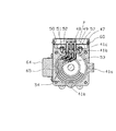
図2に示すように、電動圧縮機40は、筒形状を成す電動機ハウジング(ハウジング)41、中間ハウジング(ハウジング)42および圧縮機ハウジング(ハウジング)43により、密閉ハウジングが構成され、この密閉ハウジング内に、圧縮機部44、電動機部45、これらを連結する駆動シャフト46等が収納設置されている。
The
As shown in FIG. 2, the
電動機ハウジング41の側面には、冷媒吸入口41aと筒内側上下に冷媒通路41bが設けられ、中間ハウジング42には、複数の冷媒通路42aが設けられ、圧縮機ハウジング43には冷媒吐出口43aが設けられ、冷媒吸入口41a〜冷媒通路41b〜冷媒通路42a〜冷媒吐出口43aは、密閉ハウジング内で連通している。
A
さらに、電動機ハウジング41の上面にインバータ制御箱56が配設されている。このインバータ制御箱56は、電動機ハウジング41から伸びる構造体41cと、プリント基板(基板)57、上蓋(カバー)47等から構成されている。
図2および図3に示すように、構造体41cの中程には段部が形成され、プリント基板57はこの段部に設置され、上蓋47がその上から被せられている。この状態で、上蓋47の下端がプリント基板57の縁に当接するようになっており、この上蓋47は、構造体41cに小ねじ60で固定され、これによって上蓋47と構造体41cに挟まれたプリント基板57も固定されるようになっている。
Furthermore, an
As shown in FIGS. 2 and 3, a step portion is formed in the middle of the
プリント基板57には、パワートランジスタ(電気素子)58および多数の制御素子(電気素子)61が実装されている。そして、パワートランジスタ58は、その下面が、グリース59を介して電動機ハウジング41に密着するよう設けられている。
A power transistor (electric element) 58 and a number of control elements (electric elements) 61 are mounted on the printed
図4および図5に示すように、電動機ハウジング41の上部には、3本の端子(中継端子)48が、ガラス材49によって取付板50に溶着されている。この取付板50は、電動機ハウジング41にボルト51で固定され、パッキン52により密封されている。
3本の端子48の一端は、コネクタ53を介して3本の電線54に接続され、3本の電線54の他端は電動機巻き線55に接続されている。このとき、図5に示したように、3本の端子48は、プリント基板57に設けられた穴を貫通し、前記ガラス材49の上端がプリント基板57に当接してプリント基板57を支えるようになっている。また、図5および図6に示すように、プリント基板57には、3個の導電板62が半田付けされ、端子48に小ねじ63で固定されている。3個の導電板62はパワートランジスタ58の図示省略の出力端子に図示省略のプリント配線により接続されている。
As shown in FIGS. 4 and 5, three terminals (relay terminals) 48 are welded to the
One end of the three
図4および図7に示すように、電動機ハウジング41の側面には、平滑コンデンサ(電気素子)64がグリース65を介して電動機ハウジング41に密着設置されている。平滑コンデンサ64に設けられた2個の端子64aには、コネクタ66を介して2本の電線67の一端が接続され、2本の電線67の他端はインバータ制御箱56内の入力端子68に接続されている。
平滑コンデンサ64に設けられた2個の端子64aは、図示省略の電源からの動力線が接続可能な構造になっており、電動圧縮機40は、バッテリ等の電源から電動圧縮機40の平滑コンデンサ64に設けられた2個の端子64aに動力線が接続されて使用される。
As shown in FIGS. 4 and 7, a smoothing capacitor (electric element) 64 is closely attached to the
The two
また、図6および図7に示すように、前記のプリント基板57には2個の入力信号接続端子69が設置され、グロメット70を貫通して図示省略の車両用空調装置の制御装置からの入力信号線が接続可能な構造になっており、電動圧縮機40は、その入力信号線が接続されて使用される。
As shown in FIGS. 6 and 7, two input
このような構成により、電動圧縮機40では、バッテリ等の電源から平滑コンデンサ64に設けられた2個の端子64aに電力が供給されると、平滑コンデンサ64は電源電圧の変動を吸収し、安定化された電力を2本の電線67を通してインバータ制御箱56内の入力端子68を経由し、パワートランジスタ58へ供給する。また、図示省略の車両用空調装置の制御装置からの回転数指示信号が、プリント基板57に設置された2個の入力信号接続端子69に供給されると、回転数指示信号に対応した周波数の三相電力が、パワートランジスタ58から3本の端子48を経由して電動機巻き線55に供給される。これによって電動機部45で回転力が発生し、駆動シャフト46および圧縮機部44が回転して電動圧縮機40が運転される。
電動圧縮機40が運転されると、冷媒吸入口41aから入った低圧・低温冷媒ガスは、電動機ハウジング41と電動機部45の間の空間71a、筒内側上下に設けられた冷媒通路41b、空間71b、中間ハウジング42に設けられた複数の冷媒通路42aを順次通り、圧縮機部44で圧縮されて高圧・高温となり、圧縮機ハウジング43に設けられた冷媒吐出口43aから吐出される。
With such a configuration, in the
When the
このとき、低圧・低温冷媒ガスにより、電動機ハウジング41と電動機部45および中間ハウジング42等が冷却される。これにより、電動機ハウジング41に、グリース59を介して密着固定されているパワートランジスタ58、グリース65を介して密着固定されている平滑コンデンサ64も冷却される。
At this time, the
以上の作用により、電動機ハウジング41から伸びる構造体41cの中程に段を設けてプリント基板57を設置し、上蓋47をその上から被せて、プリント基板57を上蓋47と構造体41cに挟み込むようにしたので、プリント基板57が強固に固定され、プリント基板57の耐振性が向上する効果がある。
With the above operation, a step is provided in the middle of the
加えて、ガラス材49の上端がプリント基板57に当接してプリント基板57を支え、前記3本の端子48がプリント基板57に設けられた穴を貫通し、プリント基板57に半田付けされた3個の導電板62が端子48に小ねじ63で固定されることにより、プリント基板57の耐振性はさらに向上する効果がある。また3本の端子48が3個の導電板62に小ねじ63で固定される構成は、3本の端子48とプリント基板57の間の電線を不必要にしており、コスト低減の効果がある。
In addition, the upper end of the
さらに、電動圧縮機40が運転されることにより発熱するパワートランジスタ58、平滑コンデンサ64を、電動機ハウジング41に密着固定させたことによって、低圧・低温冷媒ガスによる冷却効果を高めて温度上昇を抑えることができる。これによって、パワートランジスタ58、平滑コンデンサ64をコンパクト化できる効果がある。
また、平滑コンデンサ64をプリント基板57内に配置しないことにより、プリント基板57内のレイアウトは自由度が広がる効果がある。
Further, the
Further, since the smoothing
なお、上記実施の形態では、電動圧縮機40の側面に平滑コンデンサ64を配設し、インバータ制御箱56、端子48等を上面に配設するようにしたが、これに限るものではなく、図8に示すように、電動圧縮機40の上面に平滑コンデンサ64を配設し、インバータ制御箱56、端子48等を側面に配設することも可能である。
これ以外にも、本発明の主旨を逸脱しない限り、上記実施の形態で挙げた構成を取捨選択したり、他の構成に適宜変更することが可能である。
In the above embodiment, the smoothing
In addition to this, as long as it does not depart from the gist of the present invention, the configuration described in the above embodiment can be selected or changed to another configuration as appropriate.
40…電動圧縮機、41c…構造体、41…電動機ハウジング(ハウジング)、42…中間ハウジング(ハウジング)、43…圧縮機ハウジング(ハウジング)、47…上蓋(カバー)、48…端子(中継端子)、49…ガラス材、50…取付板、55…電動機巻き線、57…プリント基板(基板)、58…パワートランジスタ(電気素子)、61…制御素子(電気素子)、64…平滑コンデンサ(電気素子)
DESCRIPTION OF
Claims (5)
前記電動圧縮機の外殻を形成するハウジングと、
前記電動圧縮機を制御するための電気素子が実装された基板と、
前記基板の外周部を前記ハウジングの外側で支持するため、前記ハウジングに固定された基板支持部と、
前記基板支持部に外周部を支持された前記基板を、前記基板支持部とで挟み込み、前記基板を覆うカバーと、
を備えることを特徴とする電動圧縮機。 An electric compressor constituting a refrigeration cycle,
A housing forming an outer shell of the electric compressor;
A board on which an electric element for controlling the electric compressor is mounted;
In order to support the outer peripheral portion of the substrate outside the housing, a substrate support portion fixed to the housing;
A cover that covers the substrate, sandwiching the substrate supported by the substrate support portion with an outer peripheral portion, and the substrate support portion;
An electric compressor comprising:
前記中継端子は、その一端が前記ハウジングに固定されて、前記基板を支持していることを特徴とする請求項1に記載の電動圧縮機。 A winding terminal for driving the electric compressor and the board are electrically connected, further comprising a relay terminal for supplying power input from a power source to the winding through the board,
The electric compressor according to claim 1, wherein one end of the relay terminal is fixed to the housing to support the substrate.
前記電動圧縮機の外殻を形成するハウジングと、
前記電動圧縮機を制御するための電気素子が実装された基板と、
前記電動圧縮機を駆動させるための巻き線と
前記巻き線と前記基板とを電気的に接続し、電源から入力された電力を、前記基板を介して前記巻き線に供給するとともに、一端が前記ハウジングに固定されて前記基板を支持する中継端子と、
を備えることを特徴とする電動圧縮機。 An electric compressor constituting a refrigeration cycle,
A housing forming an outer shell of the electric compressor;
A board on which an electric element for controlling the electric compressor is mounted;
A winding for driving the electric compressor, electrically connecting the winding and the substrate, supplying power input from a power source to the winding through the substrate, and one end of the winding A relay terminal fixed to the housing and supporting the substrate;
An electric compressor comprising:
Priority Applications (1)
| Application Number | Priority Date | Filing Date | Title |
|---|---|---|---|
| JP2004369684A JP2006177214A (en) | 2004-12-21 | 2004-12-21 | Electric compressor |
Applications Claiming Priority (1)
| Application Number | Priority Date | Filing Date | Title |
|---|---|---|---|
| JP2004369684A JP2006177214A (en) | 2004-12-21 | 2004-12-21 | Electric compressor |
Publications (1)
| Publication Number | Publication Date |
|---|---|
| JP2006177214A true JP2006177214A (en) | 2006-07-06 |
Family
ID=36731551
Family Applications (1)
| Application Number | Title | Priority Date | Filing Date |
|---|---|---|---|
| JP2004369684A Pending JP2006177214A (en) | 2004-12-21 | 2004-12-21 | Electric compressor |
Country Status (1)
| Country | Link |
|---|---|
| JP (1) | JP2006177214A (en) |
Cited By (16)
| Publication number | Priority date | Publication date | Assignee | Title |
|---|---|---|---|---|
| JP2008082279A (en) * | 2006-09-28 | 2008-04-10 | Denso Corp | Electric compressor |
| JP2008133729A (en) * | 2006-11-27 | 2008-06-12 | Toyota Industries Corp | Electric compressor |
| WO2009045496A1 (en) * | 2007-10-05 | 2009-04-09 | Emerson Climate Technologies, Inc. | Compressor assembly having electronics cooling system |
| JP2010163957A (en) * | 2009-01-15 | 2010-07-29 | Mitsubishi Heavy Ind Ltd | Inverter integrated electric compressor |
| WO2010131671A1 (en) | 2009-05-13 | 2010-11-18 | サンデン株式会社 | Inverter-integrated electric compressor |
| US7895003B2 (en) | 2007-10-05 | 2011-02-22 | Emerson Climate Technologies, Inc. | Vibration protection in a variable speed compressor |
| JP2012070543A (en) * | 2010-09-24 | 2012-04-05 | Panasonic Corp | Inverter-integrated type electric compressor |
| US8418483B2 (en) | 2007-10-08 | 2013-04-16 | Emerson Climate Technologies, Inc. | System and method for calculating parameters for a refrigeration system with a variable speed compressor |
| US8448459B2 (en) | 2007-10-08 | 2013-05-28 | Emerson Climate Technologies, Inc. | System and method for evaluating parameters for a refrigeration system with a variable speed compressor |
| US8459053B2 (en) | 2007-10-08 | 2013-06-11 | Emerson Climate Technologies, Inc. | Variable speed compressor protection system and method |
| US8539786B2 (en) | 2007-10-08 | 2013-09-24 | Emerson Climate Technologies, Inc. | System and method for monitoring overheat of a compressor |
| WO2014136571A1 (en) * | 2013-03-07 | 2014-09-12 | 三菱重工オートモーティブサーマルシステムズ株式会社 | Inverter-integrated electric compressor |
| US8950206B2 (en) | 2007-10-05 | 2015-02-10 | Emerson Climate Technologies, Inc. | Compressor assembly having electronics cooling system and method |
| US9541907B2 (en) | 2007-10-08 | 2017-01-10 | Emerson Climate Technologies, Inc. | System and method for calibrating parameters for a refrigeration system with a variable speed compressor |
| WO2021049273A1 (en) * | 2019-09-09 | 2021-03-18 | サンデン・アドバンストテクノロジー株式会社 | Horizontal electric compressor |
| US11206743B2 (en) | 2019-07-25 | 2021-12-21 | Emerson Climate Technolgies, Inc. | Electronics enclosure with heat-transfer element |
-
2004
- 2004-12-21 JP JP2004369684A patent/JP2006177214A/en active Pending
Cited By (34)
| Publication number | Priority date | Publication date | Assignee | Title |
|---|---|---|---|---|
| JP2008082279A (en) * | 2006-09-28 | 2008-04-10 | Denso Corp | Electric compressor |
| JP2008133729A (en) * | 2006-11-27 | 2008-06-12 | Toyota Industries Corp | Electric compressor |
| US8118564B2 (en) | 2006-11-27 | 2012-02-21 | Kabushiki Kaisha Toyota Jidoshokki | Motor-driven compressor |
| US8849613B2 (en) | 2007-10-05 | 2014-09-30 | Emerson Climate Technologies, Inc. | Vibration protection in a variable speed compressor |
| WO2009045496A1 (en) * | 2007-10-05 | 2009-04-09 | Emerson Climate Technologies, Inc. | Compressor assembly having electronics cooling system |
| US9683563B2 (en) | 2007-10-05 | 2017-06-20 | Emerson Climate Technologies, Inc. | Vibration protection in a variable speed compressor |
| US7895003B2 (en) | 2007-10-05 | 2011-02-22 | Emerson Climate Technologies, Inc. | Vibration protection in a variable speed compressor |
| KR101128776B1 (en) | 2007-10-05 | 2012-03-27 | 에머슨 클리메이트 테크놀로지즈 인코퍼레이티드 | Compressor assembly having electronics cooling system |
| US9021823B2 (en) | 2007-10-05 | 2015-05-05 | Emerson Climate Technologies, Inc. | Compressor assembly having electronics cooling system and method |
| CN101815869B (en) * | 2007-10-05 | 2013-03-06 | 艾默生环境优化技术有限公司 | Compressor assembly having electronics cooling system |
| US8950206B2 (en) | 2007-10-05 | 2015-02-10 | Emerson Climate Technologies, Inc. | Compressor assembly having electronics cooling system and method |
| US9541907B2 (en) | 2007-10-08 | 2017-01-10 | Emerson Climate Technologies, Inc. | System and method for calibrating parameters for a refrigeration system with a variable speed compressor |
| US9494354B2 (en) | 2007-10-08 | 2016-11-15 | Emerson Climate Technologies, Inc. | System and method for calculating parameters for a refrigeration system with a variable speed compressor |
| US8539786B2 (en) | 2007-10-08 | 2013-09-24 | Emerson Climate Technologies, Inc. | System and method for monitoring overheat of a compressor |
| US10962009B2 (en) | 2007-10-08 | 2021-03-30 | Emerson Climate Technologies, Inc. | Variable speed compressor protection system and method |
| US10077774B2 (en) | 2007-10-08 | 2018-09-18 | Emerson Climate Technologies, Inc. | Variable speed compressor protection system and method |
| US8448459B2 (en) | 2007-10-08 | 2013-05-28 | Emerson Climate Technologies, Inc. | System and method for evaluating parameters for a refrigeration system with a variable speed compressor |
| US8418483B2 (en) | 2007-10-08 | 2013-04-16 | Emerson Climate Technologies, Inc. | System and method for calculating parameters for a refrigeration system with a variable speed compressor |
| US9494158B2 (en) | 2007-10-08 | 2016-11-15 | Emerson Climate Technologies, Inc. | Variable speed compressor protection system and method |
| US9057549B2 (en) | 2007-10-08 | 2015-06-16 | Emerson Climate Technologies, Inc. | System and method for monitoring compressor floodback |
| US8459053B2 (en) | 2007-10-08 | 2013-06-11 | Emerson Climate Technologies, Inc. | Variable speed compressor protection system and method |
| US9476625B2 (en) | 2007-10-08 | 2016-10-25 | Emerson Climate Technologies, Inc. | System and method for monitoring compressor floodback |
| JP2010163957A (en) * | 2009-01-15 | 2010-07-29 | Mitsubishi Heavy Ind Ltd | Inverter integrated electric compressor |
| WO2010131671A1 (en) | 2009-05-13 | 2010-11-18 | サンデン株式会社 | Inverter-integrated electric compressor |
| JP2012070543A (en) * | 2010-09-24 | 2012-04-05 | Panasonic Corp | Inverter-integrated type electric compressor |
| CN105190033A (en) * | 2013-03-07 | 2015-12-23 | 三菱重工汽车空调系统株式会社 | Inverter-integrated electric compressor |
| CN105190033B (en) * | 2013-03-07 | 2017-09-01 | 三菱重工汽车空调系统株式会社 | Inverter integrated electric compressor |
| US9929618B2 (en) | 2013-03-07 | 2018-03-27 | Mitsubishi Heavy Industries Automotive Thermal Systems Co., Ltd. | Inverter-integrated electric compressor |
| JP2014173466A (en) * | 2013-03-07 | 2014-09-22 | Mitsubishi Heavy Industries Automotive Thermal Systems Co Ltd | Electric compressor integrated with inverter |
| WO2014136571A1 (en) * | 2013-03-07 | 2014-09-12 | 三菱重工オートモーティブサーマルシステムズ株式会社 | Inverter-integrated electric compressor |
| US11206743B2 (en) | 2019-07-25 | 2021-12-21 | Emerson Climate Technolgies, Inc. | Electronics enclosure with heat-transfer element |
| US11706899B2 (en) | 2019-07-25 | 2023-07-18 | Emerson Climate Technologies, Inc. | Electronics enclosure with heat-transfer element |
| WO2021049273A1 (en) * | 2019-09-09 | 2021-03-18 | サンデン・アドバンストテクノロジー株式会社 | Horizontal electric compressor |
| JP2021042687A (en) * | 2019-09-09 | 2021-03-18 | サンデン・アドバンストテクノロジー株式会社 | Horizontal electric compressor |
Similar Documents
| Publication | Publication Date | Title |
|---|---|---|
| JP4718862B2 (en) | Electric compressor | |
| JP2006177214A (en) | Electric compressor | |
| JP5472364B2 (en) | Refrigeration equipment | |
| JP5687027B2 (en) | Inverter-integrated electric compressor | |
| EP1832749B1 (en) | Air compressor | |
| EP1926361B1 (en) | Inverter attached to an electric compressor | |
| JP4200850B2 (en) | Electric compressor | |
| EP2354549B1 (en) | Inverter-integrated electric compressor and assembly method therefor | |
| JP4144465B2 (en) | Inverter-integrated electric compressor for vehicles | |
| JP5397497B2 (en) | Refrigeration equipment | |
| US10156239B2 (en) | Inverter-integrated electrical compressor | |
| JP5517652B2 (en) | Inverter-integrated electric compressor and assembly method thereof | |
| JP4200654B2 (en) | Electric refrigeration cycle equipment | |
| CN101282857A (en) | Freezers for trailers | |
| JPWO2008062598A1 (en) | Vacuum pump | |
| JP2007282309A (en) | Vehicle motor drive unit | |
| JP2006316754A5 (en) | ||
| JP2006316754A (en) | Vehicular motor-driven compressor | |
| US20100028173A1 (en) | Inverter-integrated electric compressor | |
| US11415151B2 (en) | Vacuum pump, and control device of vacuum pump | |
| JP2001136756A (en) | Motor drive device and semiconductor device cooling device | |
| JP2006316755A (en) | Vehicular motor-driven compressor | |
| CN115076779A (en) | Air conditioner and data processing equipment | |
| JP2010270760A (en) | Electric compressor for vehicle | |
| JP7630014B2 (en) | Composite Device |
Legal Events
| Date | Code | Title | Description |
|---|---|---|---|
| A621 | Written request for application examination |
Effective date: 20071105 Free format text: JAPANESE INTERMEDIATE CODE: A621 |
|
| A977 | Report on retrieval |
Free format text: JAPANESE INTERMEDIATE CODE: A971007 Effective date: 20090515 |
|
| A131 | Notification of reasons for refusal |
Free format text: JAPANESE INTERMEDIATE CODE: A131 Effective date: 20090603 |
|
| A02 | Decision of refusal |
Free format text: JAPANESE INTERMEDIATE CODE: A02 Effective date: 20091014 |