JP2006148334A - Image processing apparatus and recording system - Google Patents
Image processing apparatus and recording system Download PDFInfo
- Publication number
- JP2006148334A JP2006148334A JP2004333298A JP2004333298A JP2006148334A JP 2006148334 A JP2006148334 A JP 2006148334A JP 2004333298 A JP2004333298 A JP 2004333298A JP 2004333298 A JP2004333298 A JP 2004333298A JP 2006148334 A JP2006148334 A JP 2006148334A
- Authority
- JP
- Japan
- Prior art keywords
- value
- dot
- cyan
- magenta
- values
- Prior art date
- Legal status (The legal status is an assumption and is not a legal conclusion. Google has not performed a legal analysis and makes no representation as to the accuracy of the status listed.)
- Pending
Links
Images


Landscapes
- Ink Jet (AREA)
- Particle Formation And Scattering Control In Inkjet Printers (AREA)
- Color, Gradation (AREA)
- Image Processing (AREA)
- Facsimile Image Signal Circuits (AREA)
- Color Image Communication Systems (AREA)
Abstract
Description
本発明は画像処理方法および該方法を実現するための記録システムに関し、特に疑似階調処理によって各色の階調を表現するための量子化方法に関する。 The present invention relates to an image processing method and a recording system for realizing the method, and more particularly to a quantization method for expressing gradation of each color by pseudo gradation processing.
一般に、記録装置にてカラー画像を記録する場合、各画素に与えられた多値データ(例えば8bit 256階調)を、より低いレベルに変換する量子化処理が行われている。 例えばドットの記録・非記録という2値で濃度を表現する記録装置の場合には、量子化処理として、多値データを2値データにまで変換する誤差拡散法が一般的に知られている(非特許文献1参照。)。以下に、誤差拡散法を簡単に説明する。
In general, when a color image is recorded by a recording apparatus, a quantization process is performed to convert multi-value data (for example, 8-bit 256 gradations) given to each pixel to a lower level. For example, in the case of a recording apparatus that expresses density with binary values such as dot recording / non-recording, an error diffusion method that converts multi-value data into binary data is generally known as quantization processing ( (Refer
例えば、画像内の画素座標において、ある注目画素P(x,y)に与えられた濃度をV(x,y)、2値化のための閾値をTとする。この場合、V(x,y)がTより大きければ注目画素は記録(1:最高濃度)、Tより小さければ注目画素は非記録(0:最低濃度)と決定される。しかし、実際のV(x,y)は、最高濃度でも最低濃度でもない中間濃度の場合が殆どである。よって、入力された中間濃度V(x,y)と出力濃度(最高濃度または最低濃度0)との間には誤差E(x,y)が生じる。誤差拡散法では、この誤差E(x,y)を、注目画素の周辺画素すなわちP(x+1,y)、P(x−1,y+1)、P(x,y+1)、P(x+1,y+1)などに振り分ける。振り分け方は、特に規定されるものではないが、一般には経験的に求められた係数W0、W1、W2、W3に則って、重み付けしながら周囲に分配する。分配された値は、元々の多値データに加算され、新たなV(x,y)として閾値と比較される。 For example, in the pixel coordinates in the image, the density given to a certain pixel of interest P (x, y) is V (x, y), and the threshold for binarization is T. In this case, if V (x, y) is larger than T, the target pixel is determined to be recorded (1: highest density), and if V (x, y) is smaller than T, the target pixel is determined not to be recorded (0: lowest density). However, the actual V (x, y) is almost always an intermediate density that is neither the highest density nor the lowest density. Therefore, an error E (x, y) occurs between the input intermediate density V (x, y) and the output density (the highest density or the lowest density 0). In the error diffusion method, this error E (x, y) is converted into peripheral pixels of the target pixel, that is, P (x + 1, y), P (x-1, y + 1), P (x, y + 1), P (x + 1, y + 1). Sort to etc. The distribution method is not particularly defined, but is generally distributed to the surroundings while being weighted according to empirically obtained coefficients W0, W1, W2, and W3. The distributed value is added to the original multi-value data and compared with the threshold value as a new V (x, y).
誤差拡散法では、上記作業の繰り返しによって、全ての画素について記録或いは非記録が決定されていく。結果的に得られる画像は、注目画素周辺の平均濃度によって、元の画像の濃度が略実現されている。このような誤差拡散法によれば、比較的記録ドットの分散性にも優れ、滑らかな画像を得ることが出来る。 In the error diffusion method, recording or non-recording is determined for all pixels by repeating the above operation. In the resulting image, the density of the original image is substantially realized by the average density around the target pixel. According to such an error diffusion method, recording dots are relatively excellent in dispersibility, and a smooth image can be obtained.
また、誤差拡散法とは別に、特にドット配列の視認性を重視し、複数のドットが極力分散性の高い状態で配列するように、ブルーノイズ特性を有するマスクを用いた2値化法も提案されている(特許文献1参照)。いずれにしても、このように比較的分散性の高い状態が得られる2値化法を採用することにより、粒状感を低減し、滑らかで高画質な画像を出力することが可能となっていた。 In addition to the error diffusion method, a binarization method using a mask with blue noise characteristics is also proposed in order to place importance on the visibility of the dot arrangement and to arrange multiple dots in a highly dispersive state as much as possible. (See Patent Document 1). In any case, by adopting a binarization method that can obtain a state of relatively high dispersibility in this way, it has been possible to reduce graininess and output a smooth and high-quality image. .
ところで、複数色のインクでフルカラーの画像を記録する場合、非特許文献1に記載の誤差拡散方法や特許文献1に記載の方法を単純に適用するのみでは、画像の滑らかさを損なう場合が確認された。具体的には、1色のインクを用いて1プレーン分の画像を形成する際には、上記文献に記載の方法を採用することで滑らかな画像を得ることは出来たが、複数色のインクを用いて複数のプレーンを重ね合わせる場合には、プレーンの重ね合わせによって新たなノイズ、殊に視認性の悪いノイズ、が発生してしまったのである。
By the way, when recording a full-color image with a plurality of colors of ink, it is confirmed that the smoothness of the image is impaired only by simply applying the error diffusion method described in Non-Patent
このような問題に対し、複数の色間のドット配列を考慮した提案も既になされている(例えば、特許文献2および特許文献3参照。)。これら特許文献によれば、特に視認性に影響を与えるシアンドットとマゼンタドットとの配列に重点を置いた例を挙げ、両者がなるべく重ならないように、かつ重なった場合にも視覚的に快い状態に分散するように、両者の入力信号値の和に対し、誤差拡散処理やブルーノイズを応用する2値化法が開示されている。
In order to solve such a problem, proposals have been made in consideration of dot arrangements between a plurality of colors (for example, see
更に、上記特許文献2あるいは3を実現するためには、大掛かりなハードウエア、あるいは大容量のメモリを有するソフトウエアが要されることに着目し、より簡易な構成で、特許文献2あるいは特許文献3と略同様の効果が得られる構成も提案されている(特許文献4参照。)特許文献4によれば、例えばシアンとマゼンタのような、2つの成分(信号)のそれぞれの入力値に対し、2次元のルックアップテーブル(LUT)を参照することによって、互いのドットが極力重ならないようなドット配列を実現する構成が開示されている。更に、特許文献4においては、適用可能なLUTは2次元に限るものでなく、例えばシアン、マゼンタにイエローを加えた3成分を考慮した3次元のLUTや、より多くの次元のLUTであっても有効である旨が明記されている。
Furthermore, in order to realize the
以上説明したように、近年のカラー画像記録装置においては、色毎のドットの分散性および複数色を重ね合わせた際のドットの分散性を配慮しつつ、滑らかで高画質な画像を出力する工夫が施されていた。 As described above, in recent color image recording apparatuses, a device for outputting a smooth and high-quality image while considering the dispersibility of dots for each color and the dispersibility of dots when multiple colors are superimposed. Was given.
ところで近年では、より階調性の高い画像を出力するために、ドット径を数段階に調整可能にしたり、同色でありながら濃度の異なる複数種類のインクを記録したりと、1画素の濃度を数段階に調整可能な記録装置が多く提供されている。このような記録装置の場合には、上述した2値の誤差拡散法ではなく、これを応用した多値誤差拡散法を適用することが出来る。多値誤差拡散法においては、2値誤差拡散法と同様に、注目画素に生じた誤差を周囲に分配しながらも、その出力値は2値ではなく、記録装置が表現可能な数段階の多値となっている。 By the way, in recent years, in order to output an image with higher gradation, the dot diameter can be adjusted in several stages, or multiple types of inks having the same color but different densities can be recorded. Many recording devices that can be adjusted in several stages are provided. In the case of such a recording apparatus, not the binary error diffusion method described above but a multi-value error diffusion method to which this is applied can be applied. In the multilevel error diffusion method, as in the binary error diffusion method, the error generated in the pixel of interest is distributed to the surroundings, but the output value is not binary, and there are several stages that can be expressed by the printing apparatus. It is a value.
特許文献4の第2実施形態おいても、各画素の濃度が複数段階に調整可能な記録装置を用い、同文献特有の効果が得られるような構成が記載されている。例えば、シアンとマゼンタのような、2つの成分のそれぞれの入力値に対し、2次元のルックアップテーブル(LUT)を参照することによって、互いのドットが極力重ならず、且つ個々のインク色は多値の信号値を有するような、量子化方法が開示されている。同じシアンであっても、大きなドットと小さなドットを切り替えて記録可能な記録ヘッドが用意されている場合においては、量子化後の各画素は0〜2で階調表現され、0の場合はドット非記録、1の場合は小ドットによって記録、2の場合は大ドットによって記録と言ったように制御されるのである。このように、特許文献4に開示された多値記録においては、その画素に最終的に与えられた数段階の信号値から、その画素に記録するドットの種類が定義付けられている。
The second embodiment of
しかしながら近年においては、対応するべき記録媒体の種類が増え、その特性も様々である。同じ階調値を表現しようとする場合であっても、必要とされる大ドット(濃インク)のドット数と小ドット(淡インク)のドット数、あるいはその割合が、記録媒体の種類によって微妙に異なってくる。すなわち、記録媒体の種類に応じて、大ドット(濃インク)のドット数および小ドット(淡インク)のドット数を適切に調整する必要が生じる。しかし、特許文献4のように、たとえば2ビット(3値あるいは4値)にまで量子化された後の最終段階で、2種類のインク(濃と淡、あるいは大と小)に振り分ける構成の場合には、振り分け方の制限が強く、微妙な濃度調整をおこなうことが出来なかった。
However, in recent years, the types of recording media to be supported have increased and their characteristics have also varied. Even when trying to express the same gradation value, the number of required large dots (dark ink) and the number of small dots (light ink), or their ratio, may vary depending on the type of recording medium. Will be different. That is, it is necessary to appropriately adjust the number of large dots (dark ink) and the number of small dots (light ink) according to the type of recording medium. However, as in
よって、近年のインクジェット記録装置においては、8bit程度の多値の段階で、大ドットと小ドット(あるいは濃インクと淡インク)とを振り分け、独立したプレーンを作成した後に、例えばマゼンタ、イエローのような他色と同様にその後の画像処理を施す方法が有用されている。このような方法であれば、8bit(256階調)の状態で、任意のシアン濃度を大ドットと小ドットに振り分けることが出来、どのような特性の記録媒体であっても、各階調に対し適切で、全階調において滑らかな階調表現が可能となる。 Therefore, in a recent ink jet recording apparatus, large dots and small dots (or dark ink and light ink) are distributed in a multi-valued stage of about 8 bits, and independent planes are created. As with other colors, a method of performing subsequent image processing is useful. With such a method, an arbitrary cyan density can be divided into large dots and small dots in a state of 8 bits (256 gradations). Appropriate and smooth gradation expression is possible in all gradations.
ところが、このように、互いに色の異なるプレーンと、互いにドット径(あるいは濃度)の異なるプレーンが混在すると、先述したシアンとマゼンタの重ね合わせによって生じる画像弊害と同様に、様々な要素の重ねあわせによる弊害が懸念される。すなわち、従来のように、シアンとマゼンタの重ね合わせに着目しただけでは、ドットの分散性において不十分な状況となる。 However, when planes with different colors and planes with different dot diameters (or densities) are mixed in this way, similar to the above-mentioned image adverse effect caused by the superposition of cyan and magenta, it is caused by the superposition of various elements. There are concerns about evil. That is, as in the prior art, simply focusing on the superposition of cyan and magenta is not sufficient in terms of dot dispersibility.
この場合、複数プレーンに対応するようなN次元のLUTを、特許文献4に開示されているような構成で用意しても良いが、インクの色とドット径(濃度)とは、性質の異なる要素であり、互いを分離する意味合いや重要度も違っている。従って、これらN成分を同レベルに分離することは適当ではない。
In this case, an N-dimensional LUT corresponding to a plurality of planes may be prepared in a configuration as disclosed in
本発明は上記問題点を解決するためになされたものであり、その目的とするところは、「ドット径」と「色」のような2種類以上の要素を有する複数種類の多値信号を量子化し、擬似中間調処理によって所定の画像を表現する場合において、複数種類のドットのそれぞれを好適な状態に分散させて配置させることが可能な画像処理方法および記録システムを提供することである。 The present invention has been made to solve the above-described problems, and its object is to quantize a plurality of types of multilevel signals having two or more types of elements such as “dot diameter” and “color”. The present invention provides an image processing method and a recording system that can disperse and arrange each of a plurality of types of dots in a suitable state when a predetermined image is expressed by pseudo halftone processing.
そのために本発明においては、m種のインクそれぞれについてk段階の異なる形態で記録されるドットを少なくとも用いて記録媒体に画像を形成するための画像データを処理する画像処理方法であって、注目画素について、前記インクの種類別かつ前記ドットの形態別に、m×k種類の多値信号値を取得する工程と、該m×k種類の多値信号値それぞれに対し、近傍画素で発生したm×k種類それぞれの量子化誤差値を加算することによって、m×k種類の第2多値信号値を取得する工程と、該m×k種類の第2多値信号値をインク種別に加算して、m個の加算値を取得する工程と、m次元のルックアップテーブルを参照することにより、前記m個の加算値に基づいてm個の暫定的な量子化値を取得する工程と、該m個の暫定的な量子化値それぞれを、k個に分離することによって、m×k種類の量子化値を取得する分離工程と、該量子化値と前記第2多値信号の値に基づいて、前記注目画素で発生するm×k個の量子化誤差値を算出する算出工程と、を有することを特徴とする。 Therefore, in the present invention, there is provided an image processing method for processing image data for forming an image on a recording medium using at least dots recorded in k different forms for each of m types of ink, For each of the ink types and the dot forms, the step of obtaining m × k types of multilevel signal values, and for each of the m × k types of multilevel signal values, m × By adding the k types of quantization error values to obtain m × k types of second multilevel signal values, and adding the m × k types of second multilevel signal values to the ink types. , Obtaining m addition values, obtaining m provisional quantized values based on the m addition values by referring to an m-dimensional lookup table, and the m Each provisional quantized value This is separated into k to obtain m × k types of quantized values, and m generated at the target pixel based on the quantized values and the value of the second multilevel signal. And a calculation step of calculating k quantization error values.
また、m種のインクそれぞれについてk段階の異なる形態で記録されるドットを少なくとも用いて記録媒体に画像を形成するための画像データを処理する画像処理方法であって、注目画素について、前記インクの種類別かつ前記ドットの形態別に、m×k種類の多値信号値を取得する工程と、該m×k種類の多値信号値それぞれに対し、近傍画素で発生したm×k種類それぞれの量子化誤差値を加算することによって、m×k種類の第2多値信号値を取得する工程と、該m×k種類の第2多値信号をk段階別に加算して、k個の加算値を取得する工程と、k次元のルックアップテーブルを参照することにより、前記k個の加算値に基づいてk個の暫定的な量子化値を取得する工程と、該k個の暫定的な量子化値それぞれを、m個に分離することによって、m×k種類の量子化値を取得する分離工程と、該量子化値と前記第2多値信号値に基づいて、前記注目画素で発生するm×k個の量子化誤差値を算出する算出工程と、を有することを特徴とする。 An image processing method for processing image data for forming an image on a recording medium using at least dots recorded in different forms of k stages for each of m types of inks, A step of acquiring m × k types of multilevel signal values for each type and for each dot form, and for each of the m × k types of multilevel signal values, each of the m × k types of quantum generated in neighboring pixels A step of obtaining m × k types of second multi-level signal values by adding the error values, and adding the m × k types of second multi-level signals in k stages to obtain k additional values , Obtaining k temporary quantized values based on the k added values by referring to a k-dimensional lookup table, and the k temporary quantum To separate each digitized value into m Therefore, a separation step for obtaining m × k types of quantization values, and m × k quantization error values generated in the pixel of interest are calculated based on the quantization values and the second multilevel signal value. And a calculating step.
また、シアンに関する複数の信号とマゼンタに関する複数の信号を含む画像データについて処理する画像処理方法であって、注目画素に含まれる前記シアンに関する複数の信号の各々について、近傍画素で発生した各シアン信号夫々の量子化誤差値を加算し、当該複数の信号それぞれについて誤差加算値を取得するシアン誤差加算工程と、前記注目画素に含まれる前記マゼンタに関する複数の信号の各々について、近傍画素で発生した各マゼンタ信号夫々の量子化誤差値を加算し、当該複数の信号それぞれについて誤差加算値を取得するマゼンタ誤差加算工程と、前記シアン誤差加算工程において得られたそれぞれの誤差加算値を合計するシアン信号加算工程と、前記マゼンタ誤差加算工程において得られたそれぞれの誤差加算値を合計するマゼンタ信号加算工程と、前記シアン信号加算工程において得られるシアン加算値と前記マゼンタ信号加算工程において得られるマゼンタ加算値とに基づいて、ルックアップテーブルを参照することにより、シアンの暫定的な量子化値およびマゼンタの暫定的な量子化値を決定する決定工程と、前記シアン誤差加算工程において得られた前記複数の信号それぞれについての誤差加算値に応じて、前記決定工程において決定された前記シアンに関する暫定的な量子化値を前記シアンの複数の信号に分配し、当該シアンの複数の信号それぞれについての量子化値を決定するシアン信号分配工程と、前記マゼンタ誤差加算工程において得られた前記複数の信号それぞれについての誤差加算値に応じて、前記決定工程において決定された前記マゼンタに関する暫定的な量子化値を前記マゼンタの複数の信号に分配し、当該マゼンタの複数の信号それぞれについての量子化値を決定するマゼンタ信号分配工程と、前記シアン信号分配工程および前記マゼンタ信号分配工程において決定されたシアンおよびマゼンタの複数の信号それぞれの量子化値と、前記シアン誤差加算工程および前記マゼンタ誤差加算工程において得られた前記シアンおよびマゼンタの複数の信号それぞれの誤差加算値とに基づいて、注目画素において発生する量子化誤差値を前記シアンおよびマゼンタの複数の信号それぞれについて計算する誤差計算工程と、を備えたことを特徴とする。 An image processing method for processing image data including a plurality of signals relating to cyan and a plurality of signals relating to magenta, wherein each cyan signal generated in a neighboring pixel is obtained for each of the plurality of signals relating to cyan included in a target pixel. A cyan error addition step of adding each quantization error value and obtaining an error addition value for each of the plurality of signals, and each of the plurality of signals relating to the magenta included in the target pixel, each generated in a neighboring pixel A magenta error addition step for adding the quantization error values of each of the magenta signals and obtaining an error addition value for each of the plurality of signals, and a cyan signal addition for summing up the respective error addition values obtained in the cyan error addition step Sum of the error addition values obtained in the process and the magenta error addition process. A provisional quantization of cyan by referring to a look-up table based on a magenta signal addition step, a cyan addition value obtained in the cyan signal addition step, and a magenta addition value obtained in the magenta signal addition step; A determination step for determining a provisional quantization value of the value and magenta, and the cyan value determined in the determination step according to an error addition value for each of the plurality of signals obtained in the cyan error addition step A provisional quantized value is distributed to a plurality of cyan signals, and a cyan signal distributing step for determining a quantized value for each of the plurality of cyan signals, and the plurality of magenta error adding steps obtained in the magenta error adding step. The magenta determined in the determining step according to an error addition value for each signal A magenta signal distribution step of distributing a provisional quantized value to the plurality of magenta signals, and determining a quantized value for each of the plurality of magenta signals, the cyan signal distribution step, and the magenta signal distribution step Based on the quantized value of each of the cyan and magenta signals determined in step, and the error added value of each of the cyan and magenta signals obtained in the cyan error adding step and the magenta error adding step. And an error calculation step of calculating a quantization error value generated in the pixel of interest for each of the cyan and magenta signals.
また、ドット径あるいはドット濃度の少なくとも一方が異なるシアンの第1ドットおよび第2ドットと、ドット径あるいはドット濃度の少なくとも一方が異なるマゼンタの第1ドットおよび第2ドットとを少なくとも用いて記録媒体上に画像を形成するべく、前記画像を構成する各画素に対応した画素データに対してデータ処理を施す画像処理方法であって、注目画素に対応した画素データに基づき、シアンの第1ドット用多値信号値、シアンの第2ドット用多値信号値、マゼンタの第1ドット用多値信号値、マゼンタの第2ドット用多値信号値を生成する第1生成工程と、前記第1生成工程で生成された前記シアンの第1ドット用多値信号値と第2ドット用多値信号値を加算してシアンドット用多値信号値を生成する第2生成工程と、前記第1生成工程で生成された前記マゼンタの第1ドット用多値信号値と第2ドット用多値信号値を加算してマゼンタドット用多値信号値を生成する第3生成工程と、前記第2、第3生成工程において生成されたシアンドット用多値信号値とマゼンタドット用多値信号値に基づいて、前記注目画素についてのシアンドットおよびマゼンタドットの暫定的な量子化値を生成する第4生成工程と、前記シアンの第1ドット用多値信号値、前記シアンの第2ドット用多値信号値、および前記第4生成工程において生成されたシアンドットの暫定的な量子化値に基づいて、前記シアンの第1ドットの量子化値および前記シアンの第2ドットの量子化値を生成する第5生成工程と、前記マゼンタの第1ドット用多値信号値、前記マゼンタの第2ドット用多値信号値、および前記第4生成工程において生成されたマゼンタドットの暫定的な量子化値に基づいて、前記マゼンタの第1ドットの量子化値および前記マゼンタの第2ドットの量子化値を生成する第6生成工程と、を有することを特徴とする。 Further, on the recording medium, at least one of cyan first dots and second dots having different dot diameters or dot densities and magenta first dots and second dots having different dot diameters or dot densities are used. An image processing method for performing data processing on pixel data corresponding to each pixel constituting the image so as to form an image on the basis of pixel data corresponding to the pixel of interest. A first generation step of generating a value signal value, a cyan second dot multi-value signal value, a magenta first dot multi-value signal value, and a magenta second dot multi-value signal value; and the first generation step. A second generation step of generating a cyan dot multi-value signal value by adding the cyan first dot multi-value signal value and the second dot multi-value signal value generated in step S; A third generation step of generating a magenta dot multi-value signal value by adding the magenta first dot multi-value signal value and the second dot multi-value signal value generated in one generation step; and the second In addition, a temporary quantization value of cyan dots and magenta dots for the target pixel is generated based on the cyan dot multi-value signal value and the magenta dot multi-value signal value generated in the third generation step. Based on the generation step, the cyan first dot multilevel signal value, the cyan second dot multilevel signal value, and the provisional quantized value of the cyan dot generated in the fourth generation step A fifth generation step of generating a quantized value of the cyan first dot and a quantized value of the cyan second dot, a multi-value signal value for the first dot of the magenta, and for the second dot of the magenta Multi-value Based on the sign value and the provisional quantized value of the magenta dot generated in the fourth generating step, the quantized value of the first magenta dot and the quantized value of the second magenta dot are generated. And a sixth generation step.
また、ドット径あるいはドット濃度の少なくとも一方が異なるシアンの第1ドットおよび第2ドットと、ドット径あるいはドット濃度の少なくとも一方が異なるマゼンタの第1ドットおよび第2ドットとを少なくとも用いて記録媒体上に画像を形成すべく、前記画像を構成する各画素に対応した画素データに対しデータ処理を施す画像処理方法であって、注目画素に対応した画素データに基づき、シアンの第1ドット用多値信号値、シアンの第2ドット用多値信号値、マゼンタの第1ドット用多値信号値、マゼンタの第2ドット用多値信号値を生成する第1生成工程と、前記第1生成工程で生成された前記シアンの第1ドット用多値信号値と前記マゼンタの第1ドット用多値信号値を加算して第1ドット用多値信号値を生成する第2生成工程と、前記第1生成工程で生成された前記シアンの第2ドット用多値信号値と前記マゼンタの第2ドット用多値信号値を加算して第2ドット用多値信号値を生成する第3生成工程と、前記第2、第3生成工程において生成された第1ドット用多値信号値と第2ドット用多値信号値に基づいて、前記注目画素についての第1ドットおよび第2ドットの暫定的な量子化値を生成する第4生成工程と、前記シアンの第1ドット用多値信号値、前記マゼンタの第1ドット用多値信号値、および前記第4生成工程において生成された第1ドットの暫定的な量子化値に基づいて、前記シアンの第1ドットの量子化値および前記マゼンタの第1ドットの量子化値を生成する第5生成工程と、前記シアンの第2ドット用多値信号値、前記マゼンタの第2ドット用多値信号値、および前記第4生成工程において生成された第2ドットの暫定的な量子化値に基づいて、前記シアンの第2ドットの量子化値および前記マゼンタの第2ドットの量子化値を生成する第6生成工程と、を有することを特徴とする。 Further, on the recording medium, at least one of cyan first dots and second dots having different dot diameters or dot densities and magenta first dots and second dots having different dot diameters or dot densities are used. An image processing method for performing data processing on pixel data corresponding to each pixel constituting the image so as to form an image on the basis of pixel data corresponding to the pixel of interest, and a multivalue for cyan first dot A first generation step of generating a signal value, a multi-value signal value for cyan second dot, a multi-value signal value for magenta first dot, and a multi-value signal value for magenta second dot; and the first generation step. A second generation step of adding the generated cyan first dot multi-value signal value and the magenta first dot multi-value signal value to generate a first dot multi-value signal value A second dot multi-value signal value is generated by adding the cyan second dot multi-value signal value generated in the first generation step and the magenta second dot multi-value signal value. Based on the multi-value signal value for the first dot and the multi-value signal value for the second dot generated in the generation step and the second and third generation steps, the first dot and the second dot of the pixel of interest A fourth generation step for generating a provisional quantized value; a multi-value signal value for the first dot of cyan; a multi-value signal value for the first dot of magenta; and the fourth value generated in the fourth generation step. A fifth generation step for generating a quantized value of the first dot of cyan and a quantized value of the first dot of magenta based on a provisional quantized value of one dot; and for the second dot of cyan Multilevel signal value, for the second dot of the magenta Based on the value signal value and the provisional quantized value of the second dot generated in the fourth generating step, the quantized value of the cyan second dot and the quantized value of the magenta second dot are obtained. And a sixth generation step of generating.
更に、k段階の形態でドットを記録可能なm色を含むm色以上のインクを用いて記録媒体に画像を形成する記録システムであって、m色かつk段階別に、m×k種類の多値の濃度信号を受信する手段と、該m×k種類の多値信号それぞれに対し、量子化誤差値を加算することによって、m×k種類の被量子化多値信号値を取得する手段と、該m×k種類の被量子化多値信号を、インク色別に加算してm個の加算値を取得する手段と、m次元のルックアップテーブルを参照することにより、前記m個の加算値からm個の暫定量子化値を取得する手段と、該m個の暫定量子価値それぞれを、k個に分離することによって、m×k種類の最終量子化値を取得する分離手段と、該最終量子価値と前記被量子化多値信号の値から、m×k個の誤差値を取得する手段と、該誤差値に基づいて、前記量子化誤差を算出する手段とを具備することを特徴とする。 Furthermore, there is provided a recording system for forming an image on a recording medium using m or more inks including m colors capable of recording dots in a k-stage form, and there are m × k types of m colors and k stages. Means for receiving a density signal of values; means for obtaining m × k types of quantized multilevel signal values by adding a quantization error value to each of the m × k types of multilevel signals; The m × k kinds of quantized multilevel signals are added for each ink color to obtain m addition values, and the m addition values are referred to by referring to an m-dimensional lookup table. Means for obtaining m provisional quantized values, separation means for obtaining m × k types of final quantization values by separating each of the m provisional quantum values into k pieces, and the final M × k error values are obtained from the quantum value and the value of the quantized multilevel signal. And means, based on said error value, characterized by comprising means for calculating the quantization error.
更にまた、k段階の形態でドットを記録可能なm色を含むm色以上のインクを用いて記録媒体に画像を形成する記録システムであって、m色かつk段階別に、m×k種類の多値の濃度信号を受信する手段と、該m×k種類の多値信号それぞれに対し、量子化誤差値を加算することによって、m×k種類の被量子化多値信号値を取得する手段と、該m×k種類の被量子化多値信号を、k段階別に加算してk個の加算値を取得する手段と、k次元のルックアップテーブルを参照することにより、前記k個の加算値からk個の暫定量子化値を取得する手段と、該k個の暫定量子価値それぞれを、m個に分離することによって、m×k種類の最終量子化値を取得する分離手段と、該最終量子価値と前記被量子化多値信号の値から、m×k個の誤差値を取得する手段と、該誤差値に基づいて、前記量子化誤差を算出する手段とを具備することを特徴とする。 Furthermore, there is provided a recording system for forming an image on a recording medium using inks of m colors or more including m colors capable of recording dots in k stages, and there are m × k types of m colors and k stages. Means for receiving a multi-value density signal, and means for obtaining m × k kinds of quantized multi-value signal values by adding a quantization error value to each of the m × k kinds of multi-value signals. Means for adding the m × k kinds of quantized multi-level signals by k stages to obtain k added values, and by referring to the k-dimensional lookup table, the k additions. Means for obtaining k provisional quantized values from the values, separating means for obtaining m × k types of final quantized values by separating each of the k provisional quantum values into m pieces, and Acquire mxk error values from the final quantum value and the value of the quantized multilevel signal. Means that, based on said error value, characterized by comprising means for calculating the quantization error.
本発明によれば、複数の要素が混在する複数のプレーンを重ね合わせた出力画像においても、複数種類のドットのそれぞれを好適な状態に分散させて配置させることが出来るので、粒状感の無い一様な画像を出力することが可能となる。 According to the present invention, even in an output image obtained by superimposing a plurality of planes in which a plurality of elements are mixed, each of a plurality of types of dots can be dispersed and arranged in a suitable state. It is possible to output various images.
(第1の実施形態)
以下、図面を参照して本発明の第1の実施形態を詳細に説明する。本実施形態で適用する記録システムは、シアン、マゼンタ、ブラックおよびイエローのインクを用い、シアンおよびマゼンタのインクがそれぞれ大ドットと小ドットの2段階の大きさで形成されることが可能なインクジェット記録システムとする。本実施形態では、ブラックインクに関しては、本発明特有の分離(分散)作業は行わない。ブラックドットは他色ドットと重なっても色が優勢に出て、他色の影響を殆ど受けないからである。また、イエロードットに関しても、その視認性が他色に比べて極めて弱いことから、やはり分離(分散)作業は行わない。
(First embodiment)
Hereinafter, a first embodiment of the present invention will be described in detail with reference to the drawings. The recording system applied in this embodiment uses cyan, magenta, black, and yellow inks, and ink jet recording in which cyan and magenta inks can be formed in two levels of large dots and small dots, respectively. System. In the present embodiment, the separation (dispersion) operation unique to the present invention is not performed for the black ink. This is because even if the black dot overlaps with other color dots, the color appears dominant and is hardly affected by the other colors. Also, regarding yellow dots, the visibility is very weak compared to other colors, so separation (dispersion) work is not performed.
図1は、本実施形態における画像データ変換処理の流れを説明するためのブロック図である。図に示すように、ここに示す各処理は、記録装置とホスト装置としてのパーソナルコンピュータ(PC)によって構成されている。 FIG. 1 is a block diagram for explaining the flow of image data conversion processing in the present embodiment. As shown in the figure, each processing shown here is constituted by a recording device and a personal computer (PC) as a host device.
ホスト装置のオペレーティングシステムで動作するプログラムとしてアプリケーションやプリンタドライバがあり、アプリケーションJ0001は記録装置で記録する画像データを作成する処理を実行する。実際の記録時にはアプリケーションで作成された画像データがプリンタドライバに渡される。 There are an application and a printer driver as programs that operate in the operating system of the host device, and the application J0001 executes processing for creating image data to be recorded by the recording device. At the time of actual recording, image data created by the application is passed to the printer driver.
本実施形態の記録システムにおいては、用途に応じてユーザが記録モードをプリンタドライバから選択できるようになっている。例えば、高画質モードにするか高速モードにするか、更に記録媒体の種類などが、ここで設定可能となっている。プリンタドライバ以降の各処理は、記録モードに応じてある程度独立に設計されている。 In the recording system of this embodiment, the user can select the recording mode from the printer driver according to the application. For example, whether the image quality mode or the high-speed mode is selected, and the type of the recording medium can be set here. Each process after the printer driver is designed to some extent independently according to the recording mode.
本実施形態におけるプリンタドライバはその処理として、前段処理J0002、後段処理J0003、2次成分分割処理J0004、ハーフトーニングJ0005、および印刷データ作成J0006を有するものとする。ここで、各処理を簡単に説明すると、前段処理J0002は色域(Gamut)のマッピングを行う。そして、sRGB規格等の画像データR、G、Bによって再現される色域を、記録装置によって再現される色域内に写像するためのデータ変換を行う。具体的にはR、G、Bのそれぞれが8bitで表現されたデータを3次元のLUTを用いることにより、異なる内容のR、G、Bの8bitのデータに変換する。 Assume that the printer driver in this embodiment includes a pre-stage process J0002, a post-stage process J0003, a secondary component division process J0004, a halftoning J0005, and a print data creation J0006. Here, each process will be briefly described. The pre-stage process J0002 performs color gamut mapping. Then, data conversion is performed to map the color gamut reproduced by the image data R, G, B such as the sRGB standard into the color gamut reproduced by the recording apparatus. Specifically, data in which R, G, and B are each expressed in 8 bits is converted into 8-bit data of R, G, and B having different contents by using a three-dimensional LUT.
後段処理J0003は、上記色域のマッピングがなされたデータR、G、Bに基づき、このデータが表す色を再現するインクの組み合わせに対応した色分解データY、M、CおよびKを求める処理を行う。ここでは前段処理と同様に、3次元LUTにて補間演算を併用して行うものとする。 The post-stage process J0003 is a process for obtaining the color separation data Y, M, C, and K corresponding to the combination of inks that reproduces the color represented by the data based on the data R, G, and B on which the color gamut is mapped. Do. Here, similarly to the pre-processing, it is assumed that interpolation calculation is performed in combination with a three-dimensional LUT.
2次成分分割処理J0004では、シアン成分(信号)Cおよびマゼンタ成分(信号)Mから、それぞれの大ドットに対応する1次成分、小ドットに対応する2次成分が求められる。例えば、シアンの濃度成分Cからシアンの第1成分C1と第2成分C2を生成するには、1次元のルックアップテーブルが用いられる。すなわち、
C1=LUTC1(C)
C2=LUTC2(C)
M1=LUTM1(M)
M2=LUTM2(M)として表すことが出来る。
In the secondary component division processing J0004, a primary component corresponding to each large dot and a secondary component corresponding to a small dot are obtained from the cyan component (signal) C and the magenta component (signal) M. For example, in order to generate the cyan first component C1 and the second component C2 from the cyan density component C, a one-dimensional lookup table is used. That is,
C1 = LUTC1 (C)
C2 = LUTC2 (C)
M1 = LUTM1 (M)
It can be expressed as M2 = LUTM2 (M).
ブラックKおよびイエローに関しては、2次成分分割処理J0004は、そのままスルーで出力される。 For black K and yellow, the secondary component division processing J0004 is output as-is.
尚、ここでは各成分に対して独立した1次元のルックアップテーブルを用いたが、各成分が互いに関係しあう多次元のLUTを用いてもよい。例えば、
(C1,C2,M1,M2)=LUTColor(C、M)としてもよい。また、イエローやブラックも考慮に入れて、
(C1,C2,M1,M2,Y,K)=LUTColor(C、M、Y、K)などとしてもよい。いずれにせよ、本実施形態の2次成分分割処理J0004が施された後の画像データは、C1、C2、M1、M2、YおよびKの6成分が、それぞれ8bitで表される多値の濃度データとなっている。
Although an independent one-dimensional lookup table is used here for each component, a multidimensional LUT in which the components are related to each other may be used. For example,
(C1, C2, M1, M2) = LUTColor (C, M) may be used. Also consider yellow and black,
(C1, C2, M1, M2, Y, K) = LUTColor (C, M, Y, K) may be used. In any case, the image data after the secondary component division processing J0004 of the present embodiment is a multi-value density in which 6 components of C1, C2, M1, M2, Y, and K are each represented by 8 bits. It is data.
ハーフトーニングJ0005は、8ビットの色分解データY、M1、M2、C1、C2、Kのそれぞれについて、2ビットのデータに変換するための量子化処理を行う。本実施形態では、K(ブラック)およびY(イエロー)に関しては、上述した多値誤差拡散法を用いて256階調の8ビットデータを、3階調の2ビットデータに変換する。 Halftoning J0005 performs quantization processing for converting each of 8-bit color separation data Y, M1, M2, C1, C2, and K into 2-bit data. In the present embodiment, for K (black) and Y (yellow), 256-level 8-bit data is converted into 3-level 2-bit data using the above-described multilevel error diffusion method.
図2は、ハーフトーニングJ0005において、注目画素のシアンおよびマゼンタを互いに分離しながら、それぞれを量子化処理する工程を説明するためのフローチャートである。 FIG. 2 is a flowchart for explaining a process of performing quantization processing in the halftoning J0005 while separating cyan and magenta of the target pixel from each other.
ステップS1000にて、まず、注目画素P(x、y)に対する各成分の濃度値を取得する。すなわち、シアンの大ドット成分InC1(x、y)、シアンの小ドット成分InC2(x、y)、マゼンタの大ドット成分InM1(x、y)、マゼンタの小ドット成分InM2(x、y)をそれぞれ取得する。ここで取得される値は、2次成分分割処理より出力され、ハーフトーン処理部J0005へ入力される入力値である。 In step S1000, first, the density value of each component for the pixel of interest P (x, y) is acquired. That is, the cyan large dot component InC1 (x, y), the cyan small dot component InC2 (x, y), the magenta large dot component InM1 (x, y), and the magenta small dot component InM2 (x, y). Get each. The value acquired here is an input value output from the secondary component division process and input to the halftone processing unit J0005.
次に、ステップS1110およびステップS1130にて、シアンの第1成分InC1およびマゼンタの第1成分InM1に対し、周辺画素からの誤差分を加算し、被量子化多値信号C1(x、y)、M1(x、y)を得る。例えばシアンの周辺誤差をErrorC1(x、y)とすると、
C1(x、y)=InC1(x、y)+ErrorC1(x、y)となる。同様に、
M1(x、y)=InM1(x、y)+ErrorM1(x、y)となる。
Next, in steps S1110 and S1130, the error from the surrounding pixels is added to the cyan first component InC1 and the magenta first component InM1, and the quantized multilevel signal C1 (x, y), Obtain M1 (x, y). For example, if the peripheral error of cyan is ErrorC1 (x, y),
C1 (x, y) = InC1 (x, y) + ErrorC1 (x, y). Similarly,
M1 (x, y) = InM1 (x, y) + ErrorM1 (x, y).
次に、ステップS1120およびステップS1140にて、シアンの第2成分C2およびマゼンタの第2成分M2に対し、周辺画素からの誤差分を加算する。すなわち、
C2(x、y)=InC2(x、y)+ErrorC2(x、y)
M2(x、y)=InM2(x、y)+ErrorM2(x、y)となる。
Next, in steps S1120 and S1140, the error from the surrounding pixels is added to the second cyan component C2 and the second magenta component M2. That is,
C2 (x, y) = InC2 (x, y) + ErrorC2 (x, y)
M2 (x, y) = InM2 (x, y) + ErrorM2 (x, y).
以上のステップS1110、ステップS1120、ステップS1130、およびステップS1140の処理は順次処理を行っても良いし、並列処理を行ってもよい。 The processes in steps S1110, S1120, S1130, and S1140 described above may be performed sequentially or in parallel.
ステップS1210およびステップS1220では、シアン、マゼンタ各色の第1成分と第2成分を、それぞれ加算する。すなわち、加算値をCおよびMとすると
C=C1(x、y)+C2(x、y)
M=M1(x、y)+M2(x、y)となる。
In steps S1210 and S1220, the first component and the second component of each color of cyan and magenta are added. That is, if the added value is C and M, C = C1 (x, y) + C2 (x, y)
M = M1 (x, y) + M2 (x, y).
ステップS1300では、予め用意された2次元のLUTを参照することにより、得られたCおよびMから、OutC、およびOutMを取得する。ここで、OutC、およびOutMは、0〜6の整数で表される濃度値である。 In step S1300, OutC and OutM are acquired from C and M obtained by referring to a two-dimensional LUT prepared in advance. Here, OutC and OutM are density values represented by integers of 0 to 6.
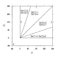
図3は、ステップS1300で参照される2次元のLUTを説明するための模式図である。図において、横軸はC、縦軸はMを示している。2次成分分割処理から出力された値は、0〜255で表されているが、ステップS1110〜ステップS1140で誤差値を加算した後では、更に幅広い領域の濃度値を有する可能性がある。よって、本実施形態のLUTにおいては、加算値CおよびMに対し、−85〜595の値に対応している。もし、CあるいはMが−85未満の場合にはこの値を−85とし、595以上の場合には、この値を595として対応する。斜めに引かれたいくつもの実線に囲まれた領域には、その領域に対応する出力値(OutC、OutM)が示されている。出力値(OutC、OutM)は、各色の第1成分と第2成分とを合わせて考慮される暫定的な出力値(暫定的な量子化値)である。 FIG. 3 is a schematic diagram for explaining the two-dimensional LUT referred to in step S1300. In the figure, the horizontal axis indicates C and the vertical axis indicates M. Although the value output from the secondary component division process is represented by 0 to 255, after adding the error value in steps S1110 to S1140, there is a possibility that the density value has a wider area. Therefore, in the LUT of the present embodiment, the added values C and M correspond to values of −85 to 595. If C or M is less than -85, this value is -85, and if it is 595 or more, this value is 595. Output values (OutC, OutM) corresponding to the regions are shown in regions surrounded by a number of oblique lines drawn obliquely. The output values (OutC, OutM) are provisional output values (provisional quantized values) that are considered together with the first and second components of each color.
図3のようにマッピングされたLUTを用いて、OutCおよびOutMを決定することにより、シアンドットとマゼンタドットとを好適に分散(分離)させることができる。 その理由を簡単に説明する。プレーンごとに量子化した後に、各色プレーンを重ね合わせた場合には、シアンドットとマゼンタドットとの重なり合いは、確率によって突発的に生じるものであった。これが画像の一様性を損ね、品位を低下させていた。しかし、本実施形態によれば、特に低濃度において、シアンとマゼンタは同じ画素内に極力記録されないように制御されている。よって、分散性に好ましい状態が得られる様になっている。また、中濃度から高濃度においても、注目画素におけるシアンとマゼンタの混色の割合が、確率に頼らずに保存されていると言う利点も得られる。 By determining OutC and OutM using the mapped LUT as shown in FIG. 3, cyan dots and magenta dots can be suitably dispersed (separated). The reason will be briefly explained. When each color plane is overlapped after quantization for each plane, the overlap of cyan dots and magenta dots occurs unexpectedly depending on the probability. This deteriorated the uniformity of the image and lowered the quality. However, according to the present embodiment, control is performed so that cyan and magenta are not recorded in the same pixel as much as possible, particularly at a low density. Therefore, a favorable state for dispersibility can be obtained. Further, there is an advantage that the ratio of the mixed color of cyan and magenta in the target pixel is stored without depending on the probability even in the middle density to the high density.
次に、ステップS1401〜ステップS1505によって、OutC、OutMをシアンの第1成分OutC1、シアンの第2成分OutC2、マゼンタの第1成分OutM1、マゼンタの第2成分OutM2に分配し、最終的な量子化値を得る。
以下に、シアンを例に分配方法を説明する。まず、ステップS1401にて、加算値CおよびC1が0より大きいか否かを判断する。CおよびC1が0より大きい場合にはステップS1403に進み、シアンの第1成分OutC1を
OutC1=INT(OutC×C1/C)
の計算式により求める。すなわち、256階調の多値情報であるC1を、0〜6で表される濃度値に対応付けるように内分計算する。
Next, in steps S1401 to S1505, OutC and OutM are distributed to the first cyan component OutC1, the second cyan component OutC2, the first magenta component OutM1, and the second magenta component OutM2, and are finally quantized. Get the value.
The distribution method will be described below using cyan as an example. First, in step S1401, it is determined whether or not the addition values C and C1 are greater than zero. If C and C1 are larger than 0, the process proceeds to step S1403, and the first cyan component OutC1 is set to OutC1 = INT (OutC × C1 / C).
It is calculated by the following formula. That is, the internal division calculation is performed so that C1 which is multi-value information of 256 gradations is associated with the density values represented by 0 to 6.
一方、ステップS1401でCおよびC1が0以下である場合には、ステップS1402へ進む。ステップS1402では、OutC1=0と定義する。 On the other hand, if C and C1 are 0 or less in step S1401, the process proceeds to step S1402. In step S1402, it is defined that OutC1 = 0.
続くステップS1404では、シアンの第2成分OutC2を求める。ここでは、OutC2=OutC−OutC1として算出する。但し、本実施形態において、OutC1およびOutC2に与えられる信号値は0〜3の範囲とする。よって、OutC1あるいはOutC2の値が3より大きな値であった場合には、ステップS1405にて、これらは強制的に3に変換される。以上の処理を、ステップS1501〜ステップS1505によってマゼンタに対しても実行する。 In the subsequent step S1404, a cyan second component OutC2 is obtained. Here, it is calculated as OutC2 = OutC−OutC1. However, in this embodiment, the signal value given to OutC1 and OutC2 is in the range of 0-3. Therefore, if the value of OutC1 or OutC2 is greater than 3, these are forcibly converted to 3 in step S1405. The above processing is executed for magenta in steps S1501 to S1505.
ステップS1600では、4つの成分それぞれに対して、発生する誤差を算出する。 In step S1600, the generated error is calculated for each of the four components.
図4は、ステップS1600で誤差値を求めるために用いる1次元のLUTである。例えば、OutC1が1であった場合、LutOut(OutC1)=85となる。注目画素における誤差値ErrorC1は、ステップS1110で得られた多値のC1と、85との差であるから、
ErrorC1=C1−LutOut(OutC1)となる。同様に、
ErrorC2=C2−LutOut(OutC2)
ErrorM1=M1−LutOut(OutM1)
ErrorM2=M2−LutOut(OutM2)となる。
図4で示したLUTは、全色に対して適用することが出来るが、各色においてそれぞれ独立したLUTが用意されていても構わない。
FIG. 4 is a one-dimensional LUT used for obtaining an error value in step S1600. For example, when OutC1 is 1, LutOut (OutC1) = 85. Since the error value ErrorC1 at the target pixel is the difference between the multivalued C1 obtained in step S1110 and 85,
ErrorC1 = C1−LutOut (OutC1). Similarly,
ErrorC2 = C2-LutOut (OutC2)
ErrorM1 = M1-LutOut (OutM1)
ErrorM2 = M2-LutOut (OutM2).
The LUT shown in FIG. 4 can be applied to all colors, but independent LUTs may be prepared for each color.
ステップS1700では、ステップS1600で得られた誤差を周辺画素に分配する。本実施形態では注目画素P(x、y)で発生した誤差を、周辺画素P(x+1、y)、P(x−1、y+1)、P(x、y+1)およびP(x+1、y+1)に分散する。分散にあたっては重み係数W0、W1、W2、W3を誤差に乗算した後に、各画素位置の誤差値に加算する。すなわち、シアンの第1成分の誤差を周辺画素に分散する場合には、
ErrorC1(x+1、y)=ErrorC1(x+1、y)+ErrorC1×W0
ErrorC1(x−1、y+1)=ErrorC1(x−1、y+1)+ErrorC1×W1
ErrorC1(x、y+1)=ErrorC1(x、y+1)+ErrorC1×W2
ErrorC1(x+1、y+1)=ErrorC1(x+1、y+1)+ErrorC1×W3
となる。C2、M1およびM2においても同様の処理が行われる。無論、誤差の分配方法は、このような方法に限られるものではない。
In step S1700, the error obtained in step S1600 is distributed to surrounding pixels. In this embodiment, the error generated in the target pixel P (x, y) is transferred to the peripheral pixels P (x + 1, y), P (x-1, y + 1), P (x, y + 1), and P (x + 1, y + 1). scatter. For dispersion, the error is multiplied by weighting factors W0, W1, W2, and W3, and then added to the error value at each pixel position. That is, when the error of the first component of cyan is distributed to surrounding pixels,
ErrorC1 (x + 1, y) = ErrorC1 (x + 1, y) + ErrorC1 × W0
ErrorC1 (x-1, y + 1) = ErrorC1 (x-1, y + 1) + ErrorC1 × W1
ErrorC1 (x, y + 1) = ErrorC1 (x, y + 1) + ErrorC1 × W2
ErrorC1 (x + 1, y + 1) = ErrorC1 (x + 1, y + 1) + ErrorC1 × W3
It becomes. Similar processing is performed in C2, M1, and M2. Of course, the error distribution method is not limited to such a method.
ステップS1800では、注目画素に対する本処理を終了する。そして、注目画素を処理の走査線に沿って次の画素に移し、再度ステップS1000からの処理を実行する。すなわち、S1000からS1800までの処理が、例えば関数Cal(x、y)として表され、処理を行うべき横方向の画素数をWidth、縦方向の画素数をLengthとすると、xおよびyが、WidthおよびLengthを超えるまで、インクリメントしながら1画素ずつ関数Cal(x、y)を繰り返して行く。以上のような処理が図1で示したハーフトーニングJ0005で実行される。 In step S1800, the process for the pixel of interest ends. Then, the target pixel is moved to the next pixel along the scanning line for processing, and the processing from step S1000 is executed again. That is, when the processing from S1000 to S1800 is expressed as, for example, a function Cal (x, y), the horizontal number of pixels to be processed is Width and the number of vertical pixels is Length, x and y are Width. The function Cal (x, y) is repeated one pixel at a time until the length exceeds the length. The above processing is executed by the halftoning J0005 shown in FIG.
プリンタドライバで行う処理の最後には、印刷データ作成処理J0006によって、上記2ビットの階調データを内容とする印刷イメージデータに印刷制御情報を加えた印刷データを作成する。 At the end of the process performed by the printer driver, print data is created by adding print control information to the print image data containing the above-mentioned 2-bit gradation data by the print data creation process J0006.
記録装置は、入力されてきた上記印刷データに対し、ドット配置パターン化処理J0007を行う。以下に本実施形態のドット配置パターン化処理J0007について簡単に説明する。上述したハーフトーン処理では、256値の多値濃度情報(8ビットデータ)を4値の階調値情報(2ビットデータ)までにレベル数を下げている。しかし、実際に本実施形態のインクジェット記録ヘッドが記録できる情報は、インクを記録するか否かの2値情報である。ドット配置パターン化処理では、0〜3の多値レベルをドットの有無を決定する2値レベルまで低減する役割を果たす。具体的には、このドット配置パターン化処理J0007では、ハーフトーン処理部からの出力値であるレベル0〜3の2ビットデータで表現される画素ごとに、その画素の階調値(レベル0〜3)に対応したドット配置パターンを割当て、これにより1画素内の複数のエリア各々にドットのオン・オフを定義し、1画素内の各エリアに「1」または「0」の1ビットの吐出データを配置する。
The recording apparatus performs a dot arrangement patterning process J0007 on the input print data. The dot arrangement patterning process J0007 of this embodiment will be briefly described below. In the halftone process described above, the number of levels is reduced from 256-level multi-value density information (8-bit data) to 4-level gradation value information (2-bit data). However, information that can be actually recorded by the ink jet recording head of this embodiment is binary information indicating whether or not to record ink. In the dot arrangement patterning process, it plays the role of reducing the multi-value level of 0 to 3 to the binary level that determines the presence or absence of dots. Specifically, in this dot arrangement patterning process J0007, for each pixel represented by 2-bit data of
図5は、本実施形態におけるドット配置パターン化処理J0007で変換する、C1およびC2の入力レベル0〜3に対する出力パターン例を示している。図の左に示した各レベル値は、ハーフトーン処理部からの出力値であるレベル0〜レベル3に相当している。右側に配列した縦2エリア×横2エリアで構成される領域は、ハーフトーン処理で出力された1画素(ピクセル)の領域に対応するもので、例えば縦横ともに600ppi(ピクセル/インチ;参考値)の画素密度に対応する大きさとなっている。また、1画素内の各エリアは、ドットのオン・オフが定義される最小単位に相当するもので、縦横ともに1200dpi(ドット/インチ;参考値)の記録密度に対応するものである。本実施形態の記録装置では、上記記録密度に対応した、縦横ともに約20μmで表現される1つのエリアに対し、大ドット2pl、小ドットは1plのインク滴が1つ記録される様に設計されている。
FIG. 5 shows an output pattern example for the
図において、丸印を記入したエリアがそれぞれのドットの記録を行うエリアを示している。レベル数が上がるに従って、記録するドット数も1つずつ増加している。本実施形態では、大ドット(C1)と小ドット(C2)がなるべく重ならないように各レベルのドット配置が配慮されている。 In the figure, the area filled with a circle indicates the area where each dot is recorded. As the number of levels increases, the number of dots to be recorded increases by one. In the present embodiment, consideration is given to the dot arrangement at each level so that the large dots (C1) and the small dots (C2) do not overlap as much as possible.
但し、このようなドット配置パターン化処理は、本発明を特徴付けるものではない。ドット配置パターン化処理におけるパターンは、ここに示した配列に限定されるものではなく、またドット配置パターン化処理を適用しない構成であっても本発明の効果を得ることは出来る。ここでは、ハーフトーニングJ0005からの出力値が数段階の多値であった場合の、階調表現の方法の1つとして、ドット配置パターン化処理を適用したに過ぎない。 However, such a dot arrangement patterning process does not characterize the present invention. The pattern in the dot arrangement patterning process is not limited to the arrangement shown here, and the effect of the present invention can be obtained even if the dot arrangement patterning process is not applied. Here, only one dot arrangement patterning process is applied as one of the gradation expression methods when the output value from the halftoning J0005 is multilevel in several stages.
本実施形態においては、ドット配置パターン化処理を施すことにより実際に吐出させるドットの配置が決定され、これが出力信号として記録ヘッドJ0010の駆動回路J0009に入力される。 In the present embodiment, the dot arrangement patterning process is performed to determine the dot arrangement to be actually ejected, and this is input as an output signal to the drive circuit J0009 of the recording head J0010.
本実施形態は、シアンとマゼンタからなるカラー要素と、大ドットと小ドットからなるドット径要素とを含んだ4プレーンの重ね合わせにおいて、2段階に分けて要素ごとに分離(分散)を行うことに特徴がある。すなわち、図2に示したフローチャートにおいては、4つのプレーンのうち、C1とC2、M1とM2をそれぞれ加算し、まずCとMという色の要素のみに大別する。更に、これらを図3に示したLUTにて好適に分散させる。これが1段階目の分離(分散)である。次に、1段階目の分離(分散)で得られた、それぞれの値から、もともとの多値の配分に従って、同色内の大ドットと小ドットの値を求めている。これが2段階目の分離(分散)となっている。 In this embodiment, in the superposition of four planes including color elements composed of cyan and magenta and dot diameter elements composed of large dots and small dots, separation (dispersion) is performed for each element in two stages. There is a feature. That is, in the flowchart shown in FIG. 2, among the four planes, C1 and C2 and M1 and M2 are added, respectively, and are roughly divided into only elements of colors C and M. Further, these are preferably dispersed by the LUT shown in FIG. This is the first stage separation (dispersion). Next, the values of large dots and small dots in the same color are obtained from the respective values obtained in the separation (dispersion) at the first stage according to the original multi-value distribution. This is the second stage separation (dispersion).
このような2段階の工程で分散(分離)させる場合、4次元のLUTを用いる場合よりも簡易な構成で実現可能でありながら、4つのブレーンの重ねあわせを配慮した場合と同様にドット同士が好適に分散され、滑らかで一様な画像を得ることが可能となる。また、CとMの間で好ましい分散状態と、大ドットと小ドットの間で好ましい分散状態とは、等しくない場合もありうる。このような場合であっても、本実施形態の構成であれば、それぞれが好ましい分散状態となる様に、1段階目の分離と2段階目の分離の手法に特徴を持たせることが可能である。 In the case of dispersion (separation) in such a two-step process, dots can be formed in the same manner as in the case of considering the superposition of four brains, although it can be realized with a simpler configuration than the case of using a four-dimensional LUT. It is possible to obtain a smooth and uniform image that is suitably dispersed. In addition, a preferable dispersion state between C and M may not be equal to a preferable dispersion state between large dots and small dots. Even in such a case, with the configuration of the present embodiment, it is possible to give characteristics to the first-stage separation method and the second-stage separation method so that each is in a preferable dispersed state. is there.
なお、以上では、図1に示したホスト装置と記録装置から構成されるインクジェット記録システムを例に説明してきたが、本実施形態の構成はこのような記録システムによってのみ実現されるものではない。例えば、プリンタドライバが行う全ての処理を、記録装置に備えられたハード構成にて実行するものであってもよい。 In the above description, the inkjet recording system including the host device and the recording apparatus illustrated in FIG. 1 has been described as an example. However, the configuration of the present embodiment is not realized only by such a recording system. For example, all processing performed by the printer driver may be executed by a hardware configuration provided in the recording apparatus.
図6は、上述したハーフトーニング処理をハードウエアによって実現するための電気回路構成を示したブロック図である。図において、1、2および4、5は、図2で説明したステップS1110、ステップS1120、ステップS1130およびステップS1140を実行するための加算器である。すなわち、ハーフトーン処理部J0005に入力される多値信号、つまり2次成分分割処理より出力された濃度値(InC1、InC2、InM1、InM2)に対し、誤差バッファ18、19、20、21に一時的に格納された誤差値をそれぞれ加算する。ここで得られた値(C1、C2,M1、M2)は別の加算器3および6に入力される。
FIG. 6 is a block diagram showing an electric circuit configuration for realizing the above-described halftoning process by hardware. In the figure, 1, 2 and 4, 5 are adders for executing Step S1110, Step S1120, Step S1130 and Step S1140 described in FIG. That is, the multi-value signal input to the halftone processing unit J0005, that is, the density value (InC1, InC2, InM1, InM2) output from the secondary component division processing is temporarily stored in the error buffers 18, 19, 20, and 21. Each stored error value is added. The values (C1, C2, M1, M2) obtained here are input to the
3および6は、ステップS1210およびステップS1220を実行するための加算器である。すなわち、シアンとマゼンタそれぞれ独立に1次成分(C1、M1)と2次成分(C2、M2)を加算する。
7は出力決定手段であり、図3で説明したLUTが格納されている。加算器3および6で得られた加算値CおよびMは、出力決定手段7に入力され、出力決定手段は、格納されたLUTを参照することにより、OutCおよびOutMを決定し、それぞれの出力分配手段8および9へと出力する。
出力分配手段8および9には、出力決定手段7からの出力値の他に、各色の1次成分の値(C1、M1)、および加算値(C、M)が入力される。出力分配手段8および9は、これら3つの値からステップS1401〜ステップS1505の処理を実行する。すなわち、各色の第1成分OutC1、OutM1および第2成分OutC2、OutM2を決定し、これを出力する。
In addition to the output value from the
出力分配手段8および9で得られた出力値OutC1、OutC2、OutM1およびOutM2は、ステップS1600を実行するために誤差計算手段10、11、12および13にもそれぞれ出力される。誤差計算手段10、11、12および13は、出力値OutC1、OutC2、OutM1およびOutM2と、加算器1、2、4および5で誤差が加算された後のC1、C2、M1およびM2とをそれぞれ比較し、誤差値ErrorC1、ErrorC2、ErrorM1およびErrorM2を算出して、誤差拡散手段14〜17へ出力する。
The output values OutC1, OutC2, OutM1 and OutM2 obtained by the output distribution means 8 and 9 are also output to the error calculation means 10, 11, 12 and 13, respectively, in order to execute step S1600. The error calculation means 10, 11, 12, and 13 respectively output the output values OutC1, OutC2, OutM1, and OutM2 and C1, C2, M1, and M2 after the errors are added by the
誤差拡散手段14〜17は、所定の重み係数に基づいて、誤差値ErrorC1、ErrorC2、ErrorM1およびErrorM2を分割し、周辺画素のアドレスごとに誤差バッファ18〜21に格納する。 The error diffusion means 14-17 divide the error values ErrorC1, ErrorC2, ErrorM1, and ErrorM2 based on a predetermined weighting coefficient, and store them in the error buffers 18-21 for each address of the peripheral pixels.
以上説明した図6の構成により、図2で説明したフローチャートの各処理を実現することが出来る。 With the configuration of FIG. 6 described above, each process of the flowchart described with reference to FIG. 2 can be realized.
なお、ステップS1401〜ステップS1505で説明した本実施形態の2段階目の分離(分散)方法においては、別のハード構成によって実現することも可能である。 Note that the second-stage separation (distribution) method of the present embodiment described in steps S1401 to S1505 can be realized by another hardware configuration.
図7は、2段階目の分離(分散)を、図2で示した方法とは異なる方法で実現するためのフローチャートである。図7において、ステップS1300とこれ以前の工程、ステップS1404、ステップS1504およびこれ以降の工程は、図2と同様とする。 FIG. 7 is a flowchart for realizing the second stage separation (dispersion) by a method different from the method shown in FIG. In FIG. 7, step S1300 and the previous steps, step S1404, step S1504 and the subsequent steps are the same as those in FIG.
本方法において、まずステップS2401でC1が0より大きいか否かを判断する。C1≦0の場合、ステップS2402へ進み、C1の出力値OutC1=0とする。一方、C>0の場合、ステップS2403へ進み、C2が0より大きいか否かを判断する。ここで、C2≦0の場合、ステップS2404へ進み、C1の出力値OutC1=OutCとする。また、ステップS2403でC2>0の場合、ステップS2405へ進み、OutC1=INT(OutC×C1/(C1+C2))とする。 In this method, first, in step S2401, it is determined whether C1 is greater than zero. If C1 ≦ 0, the process proceeds to step S2402, and the output value OutC1 = 0 of C1 is set. On the other hand, if C> 0, the process advances to step S2403 to determine whether C2 is greater than zero. Here, if C2 ≦ 0, the process proceeds to step S2404, and the output value OutC1 of Out1 is set to OutC. If C2> 0 in step S2403, the process proceeds to step S2405, where OutC1 = INT (OutC × C1 / (C1 + C2)).
続くステップS1404では、ステップS2402、ステップS2404、ステップS2405のいずれかによって得られたOutC1を用い、OutC2を、OutC2=OutC−OutC1より算出する。OutC1あるいはOutC2の値が3より大きな値であった場合には、ステップS2405にて、これらは強制的に3に変換される。 In subsequent step S1404, OutC2 is calculated from OutC2 = OutC-OutC1 using OutC1 obtained in any of steps S2402, S2404, and S2405. If the value of OutC1 or OutC2 is larger than 3, these are forcibly converted to 3 in step S2405.
以上の工程をマゼンタに対しても、並列して行う。(ステップS2501〜ステップS2505)
図8は、図7で説明した工程を実現するための電気回路構成を示したブロック図である。図6の場合と比較すると、出力分配手段8および9に入力されている値が、OutC、C1およびCではなく、OutC、C1およびC2となっている。
The above steps are also performed in parallel for magenta. (Steps S2501 to S2505)
FIG. 8 is a block diagram showing an electric circuit configuration for realizing the steps described in FIG. Compared with the case of FIG. 6, the values input to the output distribution means 8 and 9 are not OutC, C1 and C, but OutC, C1 and C2.
更に、別の2段階目の分離(分散)方法として、上記フローチャートに示したような計算式を用いるのではなく、予め用意されたLUTを用いて全ての出力値を一括に求める方法であってもよい。 Furthermore, as another separation (dispersion) method at the second stage, instead of using the calculation formula as shown in the above flowchart, it is a method for obtaining all output values at once using a LUT prepared in advance. Also good.
図9〜図11は、2段目の分離(分散)、すなわち大ドットと小ドットの分離を行うために、参照されるLUTの例を示した図である。ここでは、例えばシアンの場合、ステップS1300で得られたOutCとC1およびC2の3つのパラメータを入力値とする3次元のLUTとなる。 9 to 11 are diagrams showing examples of LUTs that are referred to in order to perform second-stage separation (dispersion), that is, separation between large dots and small dots. Here, for example, in the case of cyan, a three-dimensional LUT having three parameters OutC, C1, and C2 obtained in step S1300 as input values is obtained.
図9は、OutCが0または1であった場合の、C1およびC2からOutC1およびOutC2を求めるLUTである。図において横軸はC1、縦軸はC2であり、実線で囲まれた領域毎に、C1およびC2の値が一義的に決められている。 FIG. 9 is an LUT for obtaining OutC1 and OutC2 from C1 and C2 when OutC is 0 or 1. In the figure, the horizontal axis is C1 and the vertical axis is C2, and the values of C1 and C2 are uniquely determined for each region surrounded by a solid line.
図10は、OutCが2であった場合の、C1およびC2からOutC1およびOutC2を求めるLUTを図9と同様に示したものである。さらに図11は、OutCが3であった場合を示した図である。 FIG. 10 shows the LUT for obtaining OutC1 and OutC2 from C1 and C2 when OutC is 2, as in FIG. Further, FIG. 11 is a diagram showing a case where OutC is 3.
図12は、2段階目の分離を、1段階の工程で完了させてしまう例を示したフローチャートである。ここでは、例えば図2のステップS1401〜ステップS1405によって計算処理を交えながら行った工程を、3次元のLUTを用いることによって、ステップS3401のみで完了させてしまっている。すなわち、2段階目の分離(分散)工程を、より迅速に実行することが可能となる。 FIG. 12 is a flowchart showing an example in which the second-stage separation is completed in a one-stage process. Here, for example, the process performed while performing calculation processing in steps S1401 to S1405 in FIG. 2 is completed only in step S3401 by using a three-dimensional LUT. That is, the separation (dispersion) process in the second stage can be executed more quickly.
2段階のLUTを用いて、分離工程を実行する構成は、上述した特許文献4の図2にも開示されている。しかしながら、特許文献4に記載の構成によれば、最初のLUTは、各プレーンの多値情報を、より少ないレベルに量子化するための1次元のLUTであり、2つ目のLUTが、シアンとマゼンタのような色間を分離するための多次元のLUTとなっている。これに対し、上述した本実施形態のLUTは、2つのLUTが、双方とも分離のための多次元のLUTとなっているので、特許文献4に記載の構成とは内容を異とするものである。無論、特許文献4の効果を得るために、LUTをより簡略化するための1次元のLUTを工程の前段階に更に付け加えたとしても、本発明の特徴に影響を与えるものではない。
A configuration in which a separation process is performed using a two-stage LUT is also disclosed in FIG. However, according to the configuration described in
以上説明したように、本実施形態によれば、大ドットと小ドットによってシアンインクおよびマゼンタインクを記録可能なインクジェット記録システムにおいて、同色の大ドットの信号値(C1)と小ドットの信号値(C2)との和(C)を求めた後に、各色の和の値(CとM)から、2次元のLUTを用いて各色の量子化値(OutC)を暫定的に求めている。そして、得られた暫定値(OutC)から、互いの色は無関係な状態で、最終的な量子価値(OutC1およびOutC2)をそれぞれ求めている。これにより、複数のプレーンを重ね合わせた出力画像においても、粒状感の無い一様な品位を得ることが可能となった。 As described above, according to the present embodiment, in the inkjet recording system capable of recording cyan ink and magenta ink with large dots and small dots, the signal value (C1) of the same color and the signal value of the small dot (C1) After obtaining the sum (C) with C2), the quantized value (OutC) of each color is provisionally obtained from the sum value (C and M) of each color using a two-dimensional LUT. Then, final quantum values (OutC1 and OutC2) are obtained from the obtained provisional value (OutC) in a state where the colors are not related to each other. As a result, even in an output image obtained by superimposing a plurality of planes, it is possible to obtain uniform quality without graininess.
(第2の実施形態)
以下に、本発明の第2の実施形態を説明する。本実施形態で適用する記録システムも、第1の実施形態と同様のものを適用する。すなわち、シアン、マゼンタ、ブラックおよびイエローのインクを用い、シアンおよびマゼンタのインクがそれぞれ大ドットと小ドットの2段階の大きさで形成することが可能なインクジェット記録システムとする。本実施形態においても、画像データ変換処理の流れは図1を用いて説明できるものとする。但し、ハーフトーニングJ0005における処理方法は、第1の実施形態とは異なった内容となっている。
(Second Embodiment)
The second embodiment of the present invention will be described below. The recording system applied in this embodiment is the same as that in the first embodiment. That is, an ink jet recording system that uses cyan, magenta, black, and yellow inks and that can form cyan and magenta inks in two levels of large dots and small dots, respectively. Also in the present embodiment, it is assumed that the flow of the image data conversion process can be described with reference to FIG. However, the processing method in the halftoning J0005 is different from that in the first embodiment.
図13は、本実施形態における注目画素の量子化を行う工程を説明するためのフローチャートである。 FIG. 13 is a flowchart for explaining the process of quantizing the pixel of interest in this embodiment.
ステップS5000にて、まず、注目画素P(x、y)に対する各成分の濃度値を取得する。すなわち、シアンの大ドット成分InC1(x、y)、シアンの小ドット成分InC2(x、y)、マゼンタの大ドット成分InM1(x、y)、マゼンタの小ドット成分InM2(x、y)をそれぞれ取得する。ここで取得される値は、2次成分分割処理より出力され、ハーフトーン処理部J0005に入力される入力値である。 In step S5000, first, the density value of each component for the pixel of interest P (x, y) is acquired. That is, the cyan large dot component InC1 (x, y), the cyan small dot component InC2 (x, y), the magenta large dot component InM1 (x, y), and the magenta small dot component InM2 (x, y). Get each. The value acquired here is an input value output from the secondary component division process and input to the halftone processing unit J0005.
次に、ステップS5110およびステップS5130にて、シアンの第1成分InC1および第2成分InC2に対し、周辺画素からの誤差分を加算する。例えばシアンの周辺誤差をErrorC1(x、y)とすると、
C1(x、y)=InC1(x、y)+ErrorC1(x、y)となる。同様に、
C2(x、y)=InC2(x、y)+ErrorC2(x、y)となる。
Next, in steps S5110 and S5130, the error from the surrounding pixels is added to the cyan first component InC1 and second component InC2. For example, if the peripheral error of cyan is ErrorC1 (x, y),
C1 (x, y) = InC1 (x, y) + ErrorC1 (x, y). Similarly,
C2 (x, y) = InC2 (x, y) + ErrorC2 (x, y).
次に、ステップS5120およびステップS5140にて、マゼンタの第1成分M1および第2成分M2に対し、周辺画素からの誤差分を加算する。すなわち、
M1(x、y)=InM1(x、y)+ErrorM1(x、y)
M2(x、y)=InM2(x、y)+ErrorM2(x、y)となる。
Next, in steps S5120 and S5140, the error from the surrounding pixels is added to the first component M1 and the second component M2 of magenta. That is,
M1 (x, y) = InM1 (x, y) + ErrorM1 (x, y)
M2 (x, y) = InM2 (x, y) + ErrorM2 (x, y).
以上のステップS5110、ステップS5120、ステップS5130、およびステップS5140の処理は順次処理を行っても良いし、並列処理を行ってもよい。 The processes in steps S5110, S5120, S5130, and S5140 described above may be performed sequentially or in parallel.
ステップS5210では、シアンおよびマゼンタの第1成分を加算する。すなわち、加算値をS1とすると
S1=C1(x、y)+M1(x、y)となる。
同様に、シアンおよびマゼンタの第2成分も加算し、
S2=C2(x、y)+M2(x、y)とする。
In step S5210, the first components of cyan and magenta are added. That is, if the added value is S1, S1 = C1 (x, y) + M1 (x, y).
Similarly, add the second component of cyan and magenta,
S2 = C2 (x, y) + M2 (x, y).
ステップS5300では、予め用意された2次元のLUTを参照することにより、得られたS1およびS2から、OutS1、およびOutS2を取得する。ここでは特にLUTの詳細な説明は行わないが、大ドットおよび小ドットが好適な状態に分散されるようなマッピングになっており、出力値OutS1、およびOutS2は、0〜6の整数となっている。 In step S5300, OutS1 and OutS2 are acquired from S1 and S2 obtained by referring to a two-dimensional LUT prepared in advance. Although the LUT is not specifically described here, the mapping is such that the large dots and the small dots are distributed in a suitable state, and the output values OutS1 and OutS2 are integers of 0 to 6. Yes.
次に、ステップS5401〜ステップS5505によって、OutS1、OutS2をシアンの第1成分OutC1、シアンの第2成分OutC2、マゼンタの第1成分OutM1、マゼンタの第2成分OutM2に分配する。 Next, in steps S5401 to S5505, OutS1 and OutS2 are distributed to the first cyan component OutC1, the second cyan component OutC2, the first magenta component OutM1, and the second magenta component OutM2.
以下に、S1(大ドット)を例に説明する。まず、ステップS5401にて、加算値S1およびC1が0より大きいか否かを判断する。S1およびC1が0より大きい場合にはステップS5403に進み、シアンの第1成分OutC1を
OutC1=INT(OutS1×C1/S1)
の計算式により求める。すなわち、256階調の多値情報であるC1を、0〜6で表される濃度値に対応付けるように内分計算する。
Hereinafter, S1 (large dot) will be described as an example. First, in step S5401, it is determined whether or not the addition values S1 and C1 are greater than zero. If S1 and C1 are larger than 0, the process proceeds to step S5403, where the first cyan component OutC1 is set to OutC1 = INT (OutS1 × C1 / S1).
It is calculated by the following formula. That is, the internal division calculation is performed so that C1 which is multi-value information of 256 gradations is associated with the density values represented by 0 to 6.
一方、ステップS5401でS1が0以下である場合には、ステップS5402へ進む。ステップS5402では、OutC1=0と定義する。 On the other hand, if S1 is 0 or less in step S5401, the process proceeds to step S5402. In step S5402, it is defined that OutC1 = 0.
続くステップS5404では、マゼンタの第1成分OutM1を求める。ここでは、OutM1=OutS1−OutC1として算出する。但し、本実施形態において、OutC1およびOutM1に与えられる信号値は0〜3の範囲とする。よって、OutC1あるいはOutM1の値が3より大きな値であった場合には、ステップS5405にて、これらは強制的に3に変換される。以上の処理を、ステップS5501〜ステップS5505によってS2(小ドット)に対しても実行する。 In a succeeding step S5404, a magenta first component OutM1 is obtained. Here, it is calculated as OutM1 = OutS1-OutC1. However, in this embodiment, the signal value given to OutC1 and OutM1 is in the range of 0-3. Therefore, if the value of OutC1 or OutM1 is greater than 3, these are forcibly converted to 3 in step S5405. The above processing is executed for S2 (small dots) in steps S5501 to S5505.
ステップS5600では、4つの成分それぞれに対して、発生する誤差を算出する。ここでは、第1の実施形態と同様に図4で示した1次元のLUTを適用することが出来る。すなわち、
ErrorC1=C1−LutOut(OutC1)
ErrorC2=C2−LutOut(OutC2)
ErrorM1=M1−LutOut(OutM1)
ErrorM2=M2−LutOut(OutM2)となる。
In step S5600, the generated error is calculated for each of the four components. Here, as in the first embodiment, the one-dimensional LUT shown in FIG. 4 can be applied. That is,
ErrorC1 = C1-LutOut (OutC1)
ErrorC2 = C2-LutOut (OutC2)
ErrorM1 = M1-LutOut (OutM1)
ErrorM2 = M2-LutOut (OutM2).
ステップS5700では、ステップS5600で得られた誤差を第1の実施形態と同様の方法で周辺画素に分配する。すなわち、シアンの第1成分の誤差を周辺画素に分散する場合には、
ErrorC1(x+1、y)=ErrorC1(x+1、y)+ErrorC1×W0
ErrorC1(x−1、y+1)=ErrorC1(x−1、y+1)+ErrorC1×W1
ErrorC1(x、y+1)=ErrorC1(x、y+1)+ErrorC1×W2
ErrorC1(x+1、y+1)=ErrorC1(x+1、y+1)+ErrorC1×W3
となる。C2、M1およびM2においても同様の処理が行われる。無論、誤差の分配方法は、このような方法に限られるものではない。
In step S5700, the error obtained in step S5600 is distributed to surrounding pixels in the same manner as in the first embodiment. That is, when the error of the first component of cyan is distributed to surrounding pixels,
ErrorC1 (x + 1, y) = ErrorC1 (x + 1, y) + ErrorC1 × W0
ErrorC1 (x-1, y + 1) = ErrorC1 (x-1, y + 1) + ErrorC1 × W1
ErrorC1 (x, y + 1) = ErrorC1 (x, y + 1) + ErrorC1 × W2
ErrorC1 (x + 1, y + 1) = ErrorC1 (x + 1, y + 1) + ErrorC1 × W3
It becomes. Similar processing is performed in C2, M1, and M2. Of course, the error distribution method is not limited to such a method.
ステップS5800では、注目画素に対する本処理を終了する。そして、注目画素を処理の走査線に沿って次の画素に移し、再度ステップS5000からの処理を実行する。すなわち、S5000からS5800までの処理が、例えば関数Cal(x、y)として表され、処理を行うべき横方向の画素数をWidth、縦方向の画素数をLengthとすると、xおよびyが、WidthおよびLengthを超えるまで、インクリメントしながら1画素ずつ関数Cal(x、y)を繰り返して行く。以上のような処理が図1で示したハーフトーニングJ0005で実行される。 In step S5800, the process for the pixel of interest ends. Then, the target pixel is moved to the next pixel along the scanning line for processing, and the processing from step S5000 is executed again. That is, when the processing from S5000 to S5800 is expressed as a function Cal (x, y), for example, if the horizontal pixel number to be processed is Width and the vertical pixel number is Length, x and y are Width The function Cal (x, y) is repeated one pixel at a time until the length exceeds the length. The above processing is executed by the halftoning J0005 shown in FIG.
以上説明したように、本実施形態によれば、大ドットと小ドットによってシアンインクおよびマゼンタインクを記録可能なインクジェット記録システムにおいて、大ドットの信号値における異色間の和(S1=C1+M1)、および小ドットの信号値における異色間の和を求めた後に、それぞれの和の値(S1)から、2次元のLUTを用いて各色の量子化値(OutS1)を暫定的に求める。その後、得られた暫定値(OutS1)から、互いのドット径は無関係な状態で最終的な量子価値(OutC1、OutM1)を求める。これにより、複数のプレーンを重ね合わせた出力画像においても、粒状感の無い一様な品位を得ることが可能となった。 As described above, according to the present embodiment, in an inkjet recording system capable of recording cyan ink and magenta ink with large dots and small dots, the sum between different colors in the signal value of large dots (S1 = C1 + M1), and After obtaining the sum between the different colors in the signal value of the small dots, the quantized value (OutS1) of each color is provisionally obtained from each sum value (S1) using a two-dimensional LUT. Thereafter, the final quantum value (OutC1, OutM1) is obtained from the obtained provisional value (OutS1) while the dot diameters are not related to each other. As a result, even in an output image obtained by superimposing a plurality of planes, it is possible to obtain uniform quality without graininess.
本実施形態のように、ドット径の大きさを第1の段階で分離した後に、第2段階で色間の分離を行う方法は、ドットの分散の状態が第1の実施形態とは異なることが予想される。一般には、適用するインクの発色状態や視認性の程度などから、より好ましい形態を選択すればよい。また、必要であれば、記録媒体の種類や記録モードによって、第1の実施形態と第2の実施形態が切り替えられるような構成であってもよい。 As in the present embodiment, the method of performing separation between colors in the second stage after separating the size of the dot diameter in the first stage is different from the first embodiment in the state of dot dispersion. Is expected. In general, a more preferable form may be selected from the color development state of the applied ink, the degree of visibility, and the like. If necessary, the first embodiment and the second embodiment may be switched according to the type of recording medium and the recording mode.
(その他の実施形態)
上述した第1、第2の実施形態は、図1に示されるように2次成分割処理J0004において同系色(例えば、シアン)の成分を2成分(C1、C2)に分割しているが、本発明ではこの2次成分割処理J0004を設けることは必須ではない。例えば、後段処理部J0003においてRGB信号をC1・C2・M1・M2・Y・Kの6成分信号に変換し、この6成分信号をハーフトーンニング処理部J0005へ入力し、ハーフトーンニング処理部J0005にて上記第1、第2の実施形態で述べた通りの大小CM分離処理を行う形態であってもよい。
(Other embodiments)
In the first and second embodiments described above, as shown in FIG. 1, the component of the similar color (for example, cyan) is divided into two components (C1, C2) in the secondary generation division processing J0004. In the present invention, it is not essential to provide the secondary generation division processing J0004. For example, the post-processing unit J0003 converts RGB signals into six component signals of C1, C2, M1, M2, Y, and K, and inputs the six component signals to the halftone processing unit J0005. As described in the first and second embodiments, the large and small CM separation processing may be performed.
以上の実施形態では、特定の同系色(シアンおよびマゼンタ)について大ドットおよび小ドットの記録が可能な構成のインクジェット記録システムを例に説明してきたが、本発明は、このような構成に限定されるものではない。同系色でありながら1画素を多段階に濃度表現する方法としては、ドット径の大きさを異ならせる方法の他に、濃度の異なるインクを用意する方法もある。このような場合であっても本発明は有効となる。すなわち、上述した大ドットと小ドットとを、濃インクと淡インクに置き換えることにより、多値で出力された濃シアン、淡シアン、濃マゼンタ、淡マゼンタの各プレーンに対し、同様の効果で分離処理を実現することが出来る。更に、同系色について、ドット径とドット濃度の両方が異なる形態であってよい。このように本発明では、同系色についてドット濃度あるいはドット径の少なくとも一方が異なる形態に適用可能である。
また、本発明の効果は、シアン、マゼンタ、イエローおよびブラックの4色によって、記録される場合のみ得られるものではない。インク色の種類やドット径の大きさは更に数多くあっても可能であるし、分離するインク色もシアンとマゼンタに限定されるものではない。例えば、上記4色の他にレッド、ブルーおよびグリーンなども、大ドット、小ドット更に中ドットで記録可能な構成であっても本発明は対応可能である。この場合、例えば第1の実施形態のように、第1の分離処理で色間を分離するのであれば、ここで用いられるLUTは、色数分の次元を有するものとなる。
In the above embodiment, an inkjet recording system having a configuration capable of recording large dots and small dots for specific similar colors (cyan and magenta) has been described as an example. However, the present invention is limited to such a configuration. It is not something. As a method of expressing the density of one pixel in multiple stages while using similar colors, there is a method of preparing inks having different densities in addition to a method of varying the dot diameter. Even in such a case, the present invention is effective. In other words, by replacing the large dots and small dots described above with dark ink and light ink, separation is performed with the same effect for the dark cyan, light cyan, dark magenta, and light magenta planes output in multiple values. Processing can be realized. Further, for similar colors, both the dot diameter and the dot density may be different. As described above, the present invention can be applied to a form in which at least one of the dot density and the dot diameter is different for similar colors.
The effects of the present invention are not obtained only when recording is performed with four colors of cyan, magenta, yellow, and black. There are many types of ink colors and dot sizes, and the ink colors to be separated are not limited to cyan and magenta. For example, in addition to the above four colors, the present invention can also be applied to a configuration in which red, blue, and green can be recorded with large dots, small dots, and medium dots. In this case, for example, if the colors are separated by the first separation process as in the first embodiment, the LUT used here has dimensions corresponding to the number of colors.
更にハーフトーニングにおいても、その出力値が2bitの4値信号であることは、本発明を特徴付けるものではない。ハーフトーニングの出力値(OutC1、OutC2、OutM1、OutM2)は、2値であっても構わない。この場合、図1の示したドット配置パターン化処理は不要となる。 Further, even in halftoning, the fact that the output value is a 4-bit quaternary signal does not characterize the present invention. Halftoning output values (OutC1, OutC2, OutM1, OutM2) may be binary. In this case, the dot arrangement patterning process shown in FIG. 1 is not necessary.
ハーフトーニング後の出力先としては、ドットマトリクスによって画像を表現する記録装置であれば、インクジェット記録装置に限らずともよい。また、ハーフトーニング前の入力元からは、複数プレーンの多値信号が入力できれば良いので、図1で示したホスト装置以外にも、その多値画像を記憶する記憶媒体(フロッピーディスク(登録商標)、CD−ROMなど)、ネットワークを介しての受信、あるいはイメージスキャナ等であっても構わない。 The output destination after halftoning is not limited to the ink jet recording apparatus as long as it is a recording apparatus that expresses an image with a dot matrix. In addition to the host device shown in FIG. 1, a storage medium (floppy disk (registered trademark)) for storing the multi-valued image other than the host device shown in FIG. , CD-ROM, etc.), reception via a network, image scanner or the like.
本発明の特徴は、例えば色とドット径のような、2種類以上の要素から構成される複数種類の多値信号を量子化する際の手法にあるので、この特徴的な処理がハードウエアによって実現されても、またソフトウエアによって実現されても、本発明の範疇に含まれるものである。 The feature of the present invention lies in a technique for quantizing a plurality of types of multilevel signals composed of two or more types of elements such as colors and dot diameters. This characteristic processing is performed by hardware. It is included in the scope of the present invention whether it is realized by software or by software.
1〜6 加算器
7 出力決定手段
8,9 出力分配手段
10〜13 誤差計算手段
14〜17 誤差分散手段
18〜21 誤差バッファ
1 to 6
Claims (18)
注目画素について、前記インクの種類別かつ前記ドットの形態別に、m×k種類の多値信号値を取得する工程と、
該m×k種類の多値信号値それぞれに対し、近傍画素で発生したm×k種類それぞれの量子化誤差値を加算することによって、m×k種類の第2多値信号値を取得する工程と、
該m×k種類の第2多値信号値をインク種別に加算して、m個の加算値を取得する工程と、
m次元のルックアップテーブルを参照することにより、前記m個の加算値に基づいてm個の暫定的な量子化値を取得する工程と、
該m個の暫定的な量子化値それぞれを、k個に分離することによって、m×k種類の量子化値を取得する分離工程と、
該量子化値と前記第2多値信号の値に基づいて、前記注目画素で発生するm×k個の量子化誤差値を算出する算出工程と、
を有することを特徴とする画像処理方法。 An image processing method for processing image data for forming an image on a recording medium using at least dots recorded in different forms of k stages for each of m types of ink,
For the pixel of interest, obtaining m × k types of multilevel signal values for each ink type and each dot form;
A step of obtaining m × k types of second multilevel signal values by adding m × k types of quantization error values generated in neighboring pixels to each of the m × k types of multilevel signal values. When,
Adding the m × k types of second multi-value signal values to the ink type to obtain m added values;
obtaining m provisional quantization values based on the m addition values by referring to an m-dimensional lookup table;
Separating each of the m provisional quantized values into k, thereby obtaining m × k kinds of quantized values;
A calculation step of calculating m × k quantization error values generated in the target pixel based on the quantization value and the value of the second multi-level signal;
An image processing method comprising:
注目画素について、前記インクの種類別かつ前記ドットの形態別に、m×k種類の多値信号値を取得する工程と、
該m×k種類の多値信号値それぞれに対し、近傍画素で発生したm×k種類それぞれの量子化誤差値を加算することによって、m×k種類の第2多値信号値を取得する工程と、
該m×k種類の第2多値信号をk段階別に加算して、k個の加算値を取得する工程と、
k次元のルックアップテーブルを参照することにより、前記k個の加算値に基づいてk個の暫定的な量子化値を取得する工程と、
該k個の暫定的な量子化値それぞれを、m個に分離することによって、m×k種類の量子化値を取得する分離工程と、
該量子化値と前記第2多値信号値に基づいて、前記注目画素で発生するm×k個の量子化誤差値を算出する算出工程と、
を有することを特徴とする画像処理方法。 An image processing method for processing image data for forming an image on a recording medium using at least dots recorded in different forms of k stages for each of m types of ink,
For the pixel of interest, obtaining m × k types of multilevel signal values for each ink type and each dot form;
A step of obtaining m × k types of second multilevel signal values by adding m × k types of quantization error values generated in neighboring pixels to each of the m × k types of multilevel signal values. When,
Adding the m × k types of second multi-value signals by k stages to obtain k added values;
obtaining k provisional quantization values based on the k addition values by referring to a k-dimensional lookup table;
Separating each of the k provisional quantized values into m, thereby obtaining m × k kinds of quantized values;
A calculation step of calculating m × k quantization error values generated in the target pixel based on the quantization value and the second multi-level signal value;
An image processing method comprising:
注目画素に含まれる前記シアンに関する複数の信号の各々について、近傍画素で発生した各シアン信号夫々の量子化誤差値を加算し、当該複数の信号それぞれについて誤差加算値を取得するシアン誤差加算工程と、
前記注目画素に含まれる前記マゼンタに関する複数の信号の各々について、近傍画素で発生した各マゼンタ信号夫々の量子化誤差値を加算し、当該複数の信号それぞれについて誤差加算値を取得するマゼンタ誤差加算工程と、
前記シアン誤差加算工程において得られたそれぞれの誤差加算値を合計するシアン信号加算工程と、
前記マゼンタ誤差加算工程において得られたそれぞれの誤差加算値を合計するマゼンタ信号加算工程と、
前記シアン信号加算工程において得られるシアン加算値と前記マゼンタ信号加算工程において得られるマゼンタ加算値とに基づいて、ルックアップテーブルを参照することにより、シアンの暫定的な量子化値およびマゼンタの暫定的な量子化値を決定する決定工程と、
前記シアン誤差加算工程において得られた前記複数の信号それぞれについての誤差加算値に応じて、前記決定工程において決定された前記シアンに関する暫定的な量子化値を前記シアンの複数の信号に分配し、当該シアンの複数の信号それぞれについての量子化値を決定するシアン信号分配工程と、
前記マゼンタ誤差加算工程において得られた前記複数の信号それぞれについての誤差加算値に応じて、前記決定工程において決定された前記マゼンタに関する暫定的な量子化値を前記マゼンタの複数の信号に分配し、当該マゼンタの複数の信号それぞれについての量子化値を決定するマゼンタ信号分配工程と、前記シアン信号分配工程および前記マゼンタ信号分配工程において決定されたシアンおよびマゼンタの複数の信号それぞれの量子化値と、前記シアン誤差加算工程および前記マゼンタ誤差加算工程において得られた前記シアンおよびマゼンタの複数の信号それぞれの誤差加算値とに基づいて、注目画素において発生する量子化誤差値を前記シアンおよびマゼンタの複数の信号それぞれについて計算する誤差計算工程と、
を備えたことを特徴とする画像処理方法。 An image processing method for processing image data including a plurality of signals relating to cyan and a plurality of signals relating to magenta,
A cyan error addition step of adding a quantization error value of each cyan signal generated in a neighboring pixel for each of the plurality of cyan-related signals included in the pixel of interest and obtaining an error addition value for each of the plurality of signals; ,
A magenta error addition step of adding a quantization error value of each magenta signal generated in a neighboring pixel to each of a plurality of signals relating to the magenta included in the target pixel and obtaining an error addition value for each of the plurality of signals. When,
A cyan signal addition step of summing up the respective error addition values obtained in the cyan error addition step;
A magenta signal addition step of summing up the respective error addition values obtained in the magenta error addition step;
By referring to the lookup table based on the cyan addition value obtained in the cyan signal addition step and the magenta addition value obtained in the magenta signal addition step, the provisional quantization value of cyan and the provisional value of magenta A determination step for determining a quantized value;
In accordance with the error addition value for each of the plurality of signals obtained in the cyan error addition step, the provisional quantized values for cyan determined in the determination step are distributed to the cyan signals. A cyan signal distribution step for determining a quantized value for each of the cyan signals;
According to the error addition value for each of the plurality of signals obtained in the magenta error addition step, the provisional quantized value related to the magenta determined in the determination step is distributed to the plurality of magenta signals. A magenta signal distribution step for determining a quantization value for each of the plurality of signals of the magenta; a quantization value of each of the cyan and magenta signals determined in the cyan signal distribution step and the magenta signal distribution step; Based on the error addition value of each of the cyan and magenta signals obtained in the cyan error addition step and the magenta error addition step, the quantization error value generated in the pixel of interest is converted into a plurality of cyan and magenta signals. An error calculation process to calculate for each signal;
An image processing method comprising:
注目画素に対応した画素データに基づき、シアンの第1ドット用多値信号値、シアンの第2ドット用多値信号値、マゼンタの第1ドット用多値信号値、マゼンタの第2ドット用多値信号値を生成する第1生成工程と、
前記第1生成工程で生成された前記シアンの第1ドット用多値信号値と第2ドット用多値信号値を加算してシアンドット用多値信号値を生成する第2生成工程と、
前記第1生成工程で生成された前記マゼンタの第1ドット用多値信号値と第2ドット用多値信号値を加算してマゼンタドット用多値信号値を生成する第3生成工程と、
前記第2、第3生成工程において生成されたシアンドット用多値信号値とマゼンタドット用多値信号値に基づいて、前記注目画素についてのシアンドットおよびマゼンタドットの暫定的な量子化値を生成する第4生成工程と、
前記シアンの第1ドット用多値信号値、前記シアンの第2ドット用多値信号値、および前記第4生成工程において生成されたシアンドットの暫定的な量子化値に基づいて、前記シアンの第1ドットの量子化値および前記シアンの第2ドットの量子化値を生成する第5生成工程と、
前記マゼンタの第1ドット用多値信号値、前記マゼンタの第2ドット用多値信号値、および前記第4生成工程において生成されたマゼンタドットの暫定的な量子化値に基づいて、前記マゼンタの第1ドットの量子化値および前記マゼンタの第2ドットの量子化値を生成する第6生成工程と、
を有することを特徴とする画像処理方法。 An image is formed on a recording medium by using at least one cyan first dot and second dot having different dot diameters or dot densities, and at least one magenta first dot and second dots having different dot diameters or dot densities. An image processing method for performing data processing on pixel data corresponding to each pixel constituting the image,
Based on the pixel data corresponding to the target pixel, the first multi-value signal value for cyan, the second multi-value signal value for cyan, the first multi-value signal value for magenta, and the second multi-value signal value for magenta. A first generation step of generating a value signal value;
A second generation step of adding the cyan first dot multi-value signal value and the second dot multi-value signal value generated in the first generation step to generate a cyan dot multi-value signal value;
A third generation step of generating a magenta dot multi-value signal value by adding the magenta first dot multi-value signal value and the second dot multi-value signal value generated in the first generation step;
Based on the cyan dot multi-value signal value and the magenta dot multi-value signal value generated in the second and third generation steps, a provisional quantized value of cyan dots and magenta dots for the target pixel is generated. A fourth generation step to
Based on the cyan first dot multilevel signal value, the cyan second dot multilevel signal value, and the provisional quantization value of the cyan dot generated in the fourth generation step, the cyan A fifth generation step of generating a quantization value of the first dot and a quantization value of the cyan second dot;
Based on the magenta first dot multi-value signal value, the magenta second dot multi-value signal value, and the provisional quantization value of the magenta dot generated in the fourth generation step, A sixth generation step of generating a quantized value of the first dot and a quantized value of the second dot of the magenta;
An image processing method comprising:
(A)前記注目画素に対応した画素データを、前記シアンの第1ドット、シアンの第2ドット、マゼンタの第1ドット、マゼンタの第2ドットそれぞれに対応する独立した4種の多値信号値に変換する変換工程と、
(B)前記変換された4種の多値信号値それぞれに対して、前記シアンの第1ドット、シアンの第2ドット、マゼンタの第1ドット、マゼンタの第2ドットそれぞれについて近傍画素で発生した誤差を加算することにより、前記注目画素についての前記シアンの第1ドット用多値信号値、前記シアンの第2ドット用多値信号値、前記マゼンタの第1ドット用多値信号値、前記マゼンタの第2ドット用多値信号値を生成する生成工程とを有し、
前記シアンの第1ドットに対応した誤差は、前記第1生成工程において生成される前記シアンの第1ドット用多値信号値と、前記第5生成工程において生成される前記シアンの第1ドットの量子化値とに基づいて算出され、
前記シアンの第2ドットに対応した誤差は、前記第1生成工程において生成される前記シアンの第2ドット用多値信号値と、前記第5生成工程において生成される前記シアンの第2ドットの量子化値とに基づいて算出され、
前記マゼンタの第1ドットに対応した誤差は、前記第1生成工程において生成される前記マゼンタの第1ドット用多値信号値と、前記第6生成工程において生成される前記マゼンタの第1ドットの量子化値とに基づいて算出され、
前記マゼンタの第2ドットに対応した誤差は、前記第1生成工程において生成される前記マゼンタの第2ドット用多値信号値と、前記第6生成工程において生成される前記マゼンタの第2ドットの量子化値とに基づいて算出されることを特徴とする請求項10または11に記載の画像処理方法。 The first generation step includes
(A) The pixel data corresponding to the pixel of interest includes four independent multi-value signal values corresponding to the first cyan dot, the second cyan dot, the first magenta dot, and the second magenta dot, respectively. A conversion process for converting to
(B) For each of the four converted multi-value signal values, the first pixel of cyan, the second dot of cyan, the first dot of magenta, and the second dot of magenta are generated in neighboring pixels. By adding an error, the cyan first dot multi-value signal value, the cyan second dot multi-value signal value, the magenta first dot multi-value signal value, the magenta Generating a second dot multi-value signal value,
The error corresponding to the cyan first dot is the difference between the cyan first dot multi-value signal value generated in the first generation step and the cyan first dot generated in the fifth generation step. Calculated based on the quantized value,
The error corresponding to the cyan second dot is the difference between the cyan second dot multi-value signal value generated in the first generation step and the cyan second dot generated in the fifth generation step. Calculated based on the quantized value,
The error corresponding to the first dot of magenta includes the multi-value signal value for the first dot of magenta generated in the first generation step and the first dot of magenta generated in the sixth generation step. Calculated based on the quantized value,
The error corresponding to the second magenta dot is the difference between the magenta second dot multi-value signal value generated in the first generation step and the second magenta dot generated in the sixth generation step. The image processing method according to claim 10, wherein the image processing method is calculated based on a quantization value.
注目画素に対応した画素データに基づき、シアンの第1ドット用多値信号値、シアンの第2ドット用多値信号値、マゼンタの第1ドット用多値信号値、マゼンタの第2ドット用多値信号値を生成する第1生成工程と、
前記第1生成工程で生成された前記シアンの第1ドット用多値信号値と前記マゼンタの第1ドット用多値信号値を加算して第1ドット用多値信号値を生成する第2生成工程と、
前記第1生成工程で生成された前記シアンの第2ドット用多値信号値と前記マゼンタの第2ドット用多値信号値を加算して第2ドット用多値信号値を生成する第3生成工程と、
前記第2、第3生成工程において生成された第1ドット用多値信号値と第2ドット用多値信号値に基づいて、前記注目画素についての第1ドットおよび第2ドットの暫定的な量子化値を生成する第4生成工程と、
前記シアンの第1ドット用多値信号値、前記マゼンタの第1ドット用多値信号値、および前記第4生成工程において生成された第1ドットの暫定的な量子化値に基づいて、前記シアンの第1ドットの量子化値および前記マゼンタの第1ドットの量子化値を生成する第5生成工程と、
前記シアンの第2ドット用多値信号値、前記マゼンタの第2ドット用多値信号値、および前記第4生成工程において生成された第2ドットの暫定的な量子化値に基づいて、前記シアンの第2ドットの量子化値および前記マゼンタの第2ドットの量子化値を生成する第6生成工程と、
を有することを特徴とする画像処理方法。 An image is formed on a recording medium by using at least one cyan first dot and second dot having different dot diameters or dot densities, and at least one magenta first dot and second dots having different dot diameters or dot densities. An image processing method for performing data processing on pixel data corresponding to each pixel constituting the image,
Based on the pixel data corresponding to the target pixel, the first multi-value signal value for cyan, the second multi-value signal value for cyan, the first multi-value signal value for magenta, and the second multi-value signal value for magenta. A first generation step of generating a value signal value;
Second generation for generating a first dot multilevel signal value by adding the cyan first dot multilevel signal value generated in the first generation step and the magenta first dot multilevel signal value Process,
Third generation for generating a second dot multi-value signal value by adding the cyan second dot multi-value signal value generated in the first generation step and the magenta second dot multi-value signal value Process,
Based on the first dot multi-value signal value and the second dot multi-value signal value generated in the second and third generation steps, provisional quantum of the first dot and the second dot for the pixel of interest A fourth generation step of generating a conversion value;
Based on the cyan first dot multi-value signal value, the magenta first dot multi-value signal value, and the provisional quantized value of the first dot generated in the fourth generation step, the cyan A fifth generation step of generating a first dot quantization value and a magenta first dot quantization value;
Based on the cyan second dot multilevel signal value, the magenta second dot multilevel signal value, and the provisional quantized value of the second dot generated in the fourth generation step, the cyan A sixth generation step of generating a second dot quantization value and a magenta second dot quantization value;
An image processing method comprising:
m色かつk段階別に、m×k種類の多値の濃度信号を受信する手段と、
該m×k種類の多値信号それぞれに対し、量子化誤差値を加算することによって、m×k種類の被量子化多値信号値を取得する手段と、
該m×k種類の被量子化多値信号を、インク色別に加算してm個の加算値を取得する手段と、
m次元のルックアップテーブルを参照することにより、前記m個の加算値からm個の暫定量子化値を取得する手段と、
該m個の暫定量子価値それぞれを、k個に分離することによって、m×k種類の最終量子化値を取得する分離手段と、
該最終量子価値と前記被量子化多値信号の値から、m×k個の誤差値を取得する手段と、
該誤差値に基づいて、前記量子化誤差を算出する手段と
を具備することを特徴とする記録システム。 A recording system for forming an image on a recording medium using m or more inks including m colors capable of recording dots in a k-stage form,
means for receiving m × k types of multi-value density signals for each of m colors and k stages;
Means for obtaining m × k types of quantized multilevel signal values by adding quantization error values to each of the m × k types of multilevel signals;
Means for adding m × k types of quantized multilevel signals for each ink color to obtain m added values;
means for obtaining m provisional quantization values from the m addition values by referring to an m-dimensional lookup table;
Separating means for obtaining m × k types of final quantized values by separating each of the m provisional quantum values into k pieces;
Means for obtaining m × k error values from the final quantum value and the value of the quantized multilevel signal;
A recording system comprising: means for calculating the quantization error based on the error value.
m色かつk段階別に、m×k種類の多値の濃度信号を受信する手段と、
該m×k種類の多値信号それぞれに対し、量子化誤差値を加算することによって、m×k種類の被量子化多値信号値を取得する手段と、
該m×k種類の被量子化多値信号を、k段階別に加算してk個の加算値を取得する手段と、
k次元のルックアップテーブルを参照することにより、前記k個の加算値からk個の暫定量子化値を
取得する手段と、
該k個の暫定量子価値それぞれを、m個に分離することによって、m×k種類の最終量子化値を取得する分離手段と、
該最終量子価値と前記被量子化多値信号の値から、m×k個の誤差値を取得する手段と、
該誤差値に基づいて、前記量子化誤差を算出する手段と
を具備することを特徴とする記録システム。 A recording system for forming an image on a recording medium using m or more inks including m colors capable of recording dots in a k-stage form,
means for receiving m × k types of multi-value density signals for each of m colors and k stages;
Means for obtaining m × k types of quantized multilevel signal values by adding quantization error values to each of the m × k types of multilevel signals;
Means for adding the m × k kinds of quantized multilevel signals for each of k stages to obtain k added values;
means for obtaining k provisional quantization values from the k addition values by referring to a k-dimensional lookup table;
Separating means for obtaining m × k kinds of final quantized values by separating each of the k provisional quantum values into m,
Means for obtaining m × k error values from the final quantum value and the value of the quantized multilevel signal;
A recording system comprising: means for calculating the quantization error based on the error value.
Priority Applications (1)
| Application Number | Priority Date | Filing Date | Title |
|---|---|---|---|
| JP2004333298A JP2006148334A (en) | 2004-11-17 | 2004-11-17 | Image processing apparatus and recording system |
Applications Claiming Priority (1)
| Application Number | Priority Date | Filing Date | Title |
|---|---|---|---|
| JP2004333298A JP2006148334A (en) | 2004-11-17 | 2004-11-17 | Image processing apparatus and recording system |
Publications (1)
| Publication Number | Publication Date |
|---|---|
| JP2006148334A true JP2006148334A (en) | 2006-06-08 |
Family
ID=36627531
Family Applications (1)
| Application Number | Title | Priority Date | Filing Date |
|---|---|---|---|
| JP2004333298A Pending JP2006148334A (en) | 2004-11-17 | 2004-11-17 | Image processing apparatus and recording system |
Country Status (1)
| Country | Link |
|---|---|
| JP (1) | JP2006148334A (en) |
Cited By (3)
| Publication number | Priority date | Publication date | Assignee | Title |
|---|---|---|---|---|
| JP2008228101A (en) * | 2007-03-14 | 2008-09-25 | Canon Inc | Image processing apparatus and method |
| JP2009020617A (en) * | 2007-07-10 | 2009-01-29 | Canon Inc | Image processor, image processing method, and ink jet recording device |
| JP2011023984A (en) * | 2009-07-15 | 2011-02-03 | Canon Inc | Image processing apparatus |
-
2004
- 2004-11-17 JP JP2004333298A patent/JP2006148334A/en active Pending
Cited By (3)
| Publication number | Priority date | Publication date | Assignee | Title |
|---|---|---|---|---|
| JP2008228101A (en) * | 2007-03-14 | 2008-09-25 | Canon Inc | Image processing apparatus and method |
| JP2009020617A (en) * | 2007-07-10 | 2009-01-29 | Canon Inc | Image processor, image processing method, and ink jet recording device |
| JP2011023984A (en) * | 2009-07-15 | 2011-02-03 | Canon Inc | Image processing apparatus |
Similar Documents
| Publication | Publication Date | Title |
|---|---|---|
| US6215561B1 (en) | Image processing apparatus and image processing method | |
| JP6498132B2 (en) | Image processing apparatus, image processing method, program, and storage medium | |
| US6415065B1 (en) | Image processing apparatus and method therefor | |
| JPH077619A (en) | Document processing system | |
| JP4533218B2 (en) | Image processing apparatus, image processing method, and image processing program | |
| US7136189B2 (en) | Color halftoning using a multi-level successive-filling halftone screening algorithm | |
| CN103369195B (en) | Image processing equipment and image processing method | |
| JPH04219073A (en) | Image recorder | |
| JPH09326942A (en) | Image processing unit and method | |
| US6956673B2 (en) | Image processing apparatus and method to reduce gray levels of image | |
| US20030067617A1 (en) | Image processing apparatus, image processing method, computer program and computer-readable storage medium | |
| US20040141194A1 (en) | Ink reduction error diffusion | |
| JP5112356B2 (en) | Screen forming apparatus, screen forming method, and image processing apparatus | |
| JP2006148334A (en) | Image processing apparatus and recording system | |
| US6643030B1 (en) | Quantization method for color document reproduction in a color printing system | |
| JP4599239B2 (en) | Image processing method and image processing apparatus | |
| JP3688938B2 (en) | Image data generation method, apparatus and recording medium | |
| US8867100B2 (en) | Image quantization for digital printing | |
| JP6789664B2 (en) | Threshold matrix generator, threshold matrix generation method and program | |
| JP4742871B2 (en) | Image processing apparatus, image processing method, image processing program, and recording medium recording the program | |
| JP4535978B2 (en) | Image forming apparatus, image forming method, and image forming program | |
| JP2018121277A (en) | Image forming system, image forming apparatus, image forming method, and program | |
| JP3870056B2 (en) | Image processing apparatus and method, computer program, and computer-readable storage medium | |
| JP3683947B2 (en) | Image processing apparatus and method | |
| JP2004282344A (en) | Image processing method |