JP2006125580A - Ball screw device - Google Patents
Ball screw device Download PDFInfo
- Publication number
- JP2006125580A JP2006125580A JP2004317288A JP2004317288A JP2006125580A JP 2006125580 A JP2006125580 A JP 2006125580A JP 2004317288 A JP2004317288 A JP 2004317288A JP 2004317288 A JP2004317288 A JP 2004317288A JP 2006125580 A JP2006125580 A JP 2006125580A
- Authority
- JP
- Japan
- Prior art keywords
- circulation
- ball
- nut
- screw device
- component
- Prior art date
- Legal status (The legal status is an assumption and is not a legal conclusion. Google has not performed a legal analysis and makes no representation as to the accuracy of the status listed.)
- Withdrawn
Links
Images


Classifications
-
- F—MECHANICAL ENGINEERING; LIGHTING; HEATING; WEAPONS; BLASTING
- F16—ENGINEERING ELEMENTS AND UNITS; GENERAL MEASURES FOR PRODUCING AND MAINTAINING EFFECTIVE FUNCTIONING OF MACHINES OR INSTALLATIONS; THERMAL INSULATION IN GENERAL
- F16H—GEARING
- F16H25/00—Gearings comprising primarily only cams, cam-followers and screw-and-nut mechanisms
- F16H25/18—Gearings comprising primarily only cams, cam-followers and screw-and-nut mechanisms for conveying or interconverting oscillating or reciprocating motions
- F16H25/20—Screw mechanisms
- F16H25/22—Screw mechanisms with balls, rollers, or similar members between the co-operating parts; Elements essential to the use of such members
- F16H25/2204—Screw mechanisms with balls, rollers, or similar members between the co-operating parts; Elements essential to the use of such members with balls
- F16H25/2214—Screw mechanisms with balls, rollers, or similar members between the co-operating parts; Elements essential to the use of such members with balls with elements for guiding the circulating balls
- F16H25/2223—Cross over deflectors between adjacent thread turns, e.g. S-form deflectors connecting neighbouring threads
-
- F—MECHANICAL ENGINEERING; LIGHTING; HEATING; WEAPONS; BLASTING
- F16—ENGINEERING ELEMENTS AND UNITS; GENERAL MEASURES FOR PRODUCING AND MAINTAINING EFFECTIVE FUNCTIONING OF MACHINES OR INSTALLATIONS; THERMAL INSULATION IN GENERAL
- F16H—GEARING
- F16H25/00—Gearings comprising primarily only cams, cam-followers and screw-and-nut mechanisms
- F16H25/18—Gearings comprising primarily only cams, cam-followers and screw-and-nut mechanisms for conveying or interconverting oscillating or reciprocating motions
- F16H25/20—Screw mechanisms
- F16H25/22—Screw mechanisms with balls, rollers, or similar members between the co-operating parts; Elements essential to the use of such members
- F16H25/2204—Screw mechanisms with balls, rollers, or similar members between the co-operating parts; Elements essential to the use of such members with balls
- F16H25/2214—Screw mechanisms with balls, rollers, or similar members between the co-operating parts; Elements essential to the use of such members with balls with elements for guiding the circulating balls
Landscapes
- Engineering & Computer Science (AREA)
- General Engineering & Computer Science (AREA)
- Mechanical Engineering (AREA)
- Transmission Devices (AREA)
Abstract
Description
本発明は、例えば工作機械や射出成型機等の各種機械装置に用いられるボールねじ装置に関する。 The present invention relates to a ball screw device used in various machine devices such as machine tools and injection molding machines.
従来のこの種のボールねじ装置としては、例えば図12に示すものが知られている。
このボールねじ装置1は、外周面に螺旋状のねじ溝2を有するねじ軸3に、内周面にねじ溝2に対応する螺旋状のねじ溝4を有するナット6が螺合されている。
ナット6のねじ溝4とねじ軸3のねじ溝2とは互いに対向して両者の間に負荷を受ける螺旋軌道を形成しており、該螺旋軌道には転動体としての多数のボール5が転動可能に装填されている。そして、ねじ軸3(又はナット6)の回転により、ナット6(又はねじ軸3)がボール5の転動を介して軸方向に移動するようになっている。
As a conventional ball screw device of this type, for example, the one shown in FIG. 12 is known.
In this ball screw device 1, a
The
また、ナット6の周方向の側面の一部は平坦面とされ、この平坦面に両ねじ溝2,4間に連通する一対の循環孔7をナット6の軸線に対して略直交する方向に穿孔して、この一対の循環孔7に略コ字状をなすチューブ状の循環部品8の両端をねじ軸3を跨ぐように嵌め込むことにより、両ねじ溝2,4間の螺旋軌道に沿って公転するボール5を循環部品8の一方の端部から掬い上げてナット6の外部に導き、他方の端部から前記螺旋軌道に戻すボール循環経路9(図13参照)を循環部品8の内部に形成している。
Further, a part of the side surface in the circumferential direction of the
ところで、このようなチューブ式の循環部品では、ナット6の側面方向からボール5をナット6のねじ溝4から完全に離し、多列化が可能な外部循環方式であるため、特に小リード品の高負荷容量化には好適であるが、最近のボールねじ装置の高回転化に伴って、ボールが循環部品に衝突するスピードが速くなって衝突エネルギーが大きくなると、循環部品やねじ溝(ねじ溝の両肩部など含む)が破損して高速化への妨げとなる
そこで、ボール5のスムースな掬い上げを実現するために、樹脂製の循環部品(図示せず)を2つ割れとして、ナット6の循環孔7に嵌合された循環部品の脚部内の循環経路の中心軸線を両ねじ溝2,4の接線方向及びリード角方向に略一致(螺旋軌道の接線方向と略一致)するように配置したものが提案されている(例えば特許文献1及び特許文献2参照)
By the way, in such a tube-type circulation part, since the ball 5 is completely separated from the
ところで、上記特許文献1及び2記載のボールねじ装置においては、循環部品のボール循環経路内でのボール5の方向変換時のスムースな転動を確保して該ボール循環経路内の摩耗等を防止するためには、ボール循環経路の湾曲部の曲げR寸法は極力大きいことが望ましい。
しかしながら、図13(a)に示すように、ボール循環経路9の曲げR寸法が小さい状態から図13(b)に示すように、単純に曲げR寸法を大きくすることは、循環部品8の大型化を招き、スペース効率が悪い。なお、図において符号8bは循環部品8のナット4の平坦面との接触面を示す。
By the way, in the ball screw device described in Patent Documents 1 and 2, smooth rolling is ensured at the time of changing the direction of the ball 5 in the ball circulation path of the circulation part to prevent wear in the ball circulation path. In order to achieve this, it is desirable that the bending R dimension of the curved portion of the ball circulation path be as large as possible.
However, as shown in FIG. 13A, simply increasing the bending R dimension from a state where the bending R dimension of the ball circulation path 9 is small as shown in FIG. Space efficiency is poor. In the figure,
また、循環部品8の形状を変更することなく、曲げR寸法を大きくしたり、ボール循環経路9をねじ軸3側に寄せる場合には、循環部品8の大型化を免れることができるが、一方で循環部品8のボール循環経路9の内周側の角隅部8aの肉厚が局部的に薄くなって循環部品8の強度低下や樹脂射出成形時の変形等を招くことがある。
さらに場合によっては、図13(c)に示すように、ボール循環経路9が循環部品8からはみ出すことになり、結局、ボール循環経路9の曲げR寸法を大きくすることは難しいという問題がある。
本発明はこのような不都合を解消するためになされたものであり、循環部品の大型化を招くことなく、ボール循環経路の曲げR寸法を大きくすることができると共に、循環部品の強度低下を防止することができるボールねじ装置を提供することを目的とする。
Further, when the bending R dimension is increased or the ball circulation path 9 is moved closer to the screw shaft 3 without changing the shape of the
Furthermore, as shown in FIG. 13C, there is a problem that the ball circulation path 9 protrudes from the
The present invention has been made to eliminate such inconveniences, and can increase the bending R dimension of the ball circulation path without causing an increase in the size of the circulation part, and prevents a reduction in the strength of the circulation part. An object of the present invention is to provide a ball screw device that can be used.
上記目的を達成するために、請求項1に係る発明は、外周面に螺旋状のねじ溝を有するねじ軸と、該ねじ軸の前記ねじ溝に対応する螺旋状のねじ溝を内周面に有して前記ねじ軸に螺合されるナットと、前記両ねじ溝間の螺旋軌道に転動可能に装填された多数のボールと、前記螺旋軌道を転動する前記ボールを、前記ナットの周方向の側面に該ナットの軸線に対して略直交する方向に穿孔された一対の循環孔の内の一方の循環孔から該ナットの外部に導き、他方の循環孔から前記螺旋軌道に戻すボール循環経路を内部に形成すべく前記各循環孔に両端部が嵌合された循環部品とを備え、
該循環部品が、前記ナットの前記循環孔に嵌合される一対の脚部と、該一対の脚部を接続する本体とを具備するボールねじ装置において、
前記循環部品の前記ボール循環経路の内周側における前記脚部と前記本体との間に増肉部を設けたことを特徴とする。
In order to achieve the above object, the invention according to claim 1 is directed to a screw shaft having a spiral thread groove on the outer peripheral surface, and a spiral thread groove corresponding to the screw groove of the screw shaft on the inner peripheral surface. A nut that is screwed onto the screw shaft, a plurality of balls that are slidably loaded on the spiral track between the two screw grooves, and the ball that rolls on the spiral track. Ball circulation that leads to the outside of the nut from one circulation hole of a pair of circulation holes drilled in a direction substantially perpendicular to the axis of the nut on the side surface in the direction, and returns to the spiral track from the other circulation hole A circulation part having both ends fitted to the circulation holes to form a path therein;
In the ball screw device, wherein the circulating component includes a pair of legs fitted into the circulation hole of the nut, and a main body connecting the pair of legs.
A thickening portion is provided between the leg portion and the main body on the inner peripheral side of the ball circulation path of the circulation component.
請求項2に係る発明は、請求項1において、前記循環孔の前記ナットの外周側の開口縁の一部に前記循環部品の増肉部に対応する逃げ部を設けたことを特徴とする。
請求項3に係る発明は、請求項2において、前記逃げ部を、前記循環孔の前記ナットの外周側の開口縁の一部に該循環孔の軸線と略同一方向からざぐり加工を施して形成したことを特徴とする。
The invention according to claim 2 is characterized in that, in claim 1, a relief portion corresponding to the thickened portion of the circulation component is provided in a part of the opening edge of the circulation hole on the outer peripheral side of the nut.
According to a third aspect of the present invention, in the second aspect, the relief portion is formed by counterboring a part of an opening edge of the circulation hole on the outer peripheral side of the nut from a substantially same direction as the axis of the circulation hole. It is characterized by that.
請求項4に係る発明は、請求項1〜3のいずれか一項において、前記脚部内の前記ボール循環経路が前記循環孔の軸線に対して傾斜して形成されたことを特徴とする。
請求項5に係る発明は、請求項1〜4のいずれか一項において、互いに隣り合う各ボール間に保持ピースを介装したことを特徴とする。
請求項6に係る発明は、請求項1〜5のいずれか一項において、前記循環部品を、前記ボール循環経路の略経路方向に沿って2つ以上に分割したことを特徴とする。
According to a fourth aspect of the present invention, in any one of the first to third aspects, the ball circulation path in the leg portion is formed to be inclined with respect to the axis of the circulation hole.
According to a fifth aspect of the present invention, in any one of the first to fourth aspects, a holding piece is interposed between the adjacent balls.
According to a sixth aspect of the present invention, in any one of the first to fifth aspects, the circulating component is divided into two or more along a substantially path direction of the ball circulation path.
本発明によれば、循環部品の前記ボール循環経路の内周側における脚部と本体との間に増肉部を設けているので、循環部品の大型化を招くことなく、ボール循環経路の曲げR寸法を大きくすることができると共に、循環部品の強度低下を防止することができる。
また、循環孔のナットの外周側の開口縁の一部に循環部品の増肉部に対応する逃げ部を設けることで、循環部品の増肉部とナットとの干渉を確実に防止することができる。
According to the present invention, since the thickening portion is provided between the leg portion and the main body on the inner peripheral side of the ball circulation path of the circulation part, the bending of the ball circulation path is not caused without increasing the size of the circulation part. The R dimension can be increased and the strength of the circulating component can be prevented from being reduced.
In addition, by providing a relief part corresponding to the thickened part of the circulating part at a part of the opening edge on the outer peripheral side of the nut of the circulating hole, it is possible to reliably prevent interference between the thickened part of the circulating part and the nut. it can.
この場合、前記逃げ部を、循環孔のナットの外周側の開口縁の一部に該循環孔の軸線と略同一方向からざぐり加工を施して形成することで、ナット側の加工コストを最小限に押えることができる。
更に、循環部品の脚部内のボール循環経路が循環孔の軸線に対して傾斜して形成されることで、略接線方向で、且つ略リード角方向のボールのすくい上げを容易に実現することができる。
In this case, the relief portion is formed by spotting a part of the opening edge on the outer peripheral side of the nut of the circulation hole from substantially the same direction as the axis of the circulation hole, thereby minimizing the processing cost on the nut side. You can hold on.
Furthermore, since the ball circulation path in the leg portion of the circulation component is formed to be inclined with respect to the axis of the circulation hole, it is possible to easily pick up the ball in the substantially tangential direction and in the substantially lead angle direction. .
以下、本発明の実施の形態の一例を図を参照して説明する。
図1は本発明の実施の形態の一例であるボールねじ装置の平面図、図2は図1の右側面図、図3は循環部品の分割体の斜視図、図4は増肉部を設けていない分割体を示す図、図5及び図6は増肉部を設けた分割体を示す図、図7はナットを平坦面側から見た平面図、図8は図7のX−X線断面図、図9はナットを平坦面側から見た平面図、図10は図9のX−X線断面図、図11は保持ピースを説明するための図である。
Hereinafter, an example of an embodiment of the present invention will be described with reference to the drawings.
1 is a plan view of a ball screw device as an example of an embodiment of the present invention, FIG. 2 is a right side view of FIG. 1, FIG. 3 is a perspective view of a divided body of circulating parts, and FIG. FIG. 5 and FIG. 6 are views showing the divided body provided with the thickened portion, FIG. 7 is a plan view of the nut viewed from the flat surface side, and FIG. 8 is a line XX in FIG. 9 is a plan view of the nut as viewed from the flat surface side, FIG. 10 is a sectional view taken along line XX of FIG. 9, and FIG. 11 is a view for explaining the holding piece.
本発明の実施の形態の一例であるボールねじ装置10は、図1及び図2に示すように、外周面に螺旋状のねじ溝11を有するねじ軸12に、内周面にねじ溝11に対応する螺旋状のねじ溝13を有するナット14が嵌合されており、ナット14のねじ溝13とねじ軸12のねじ溝11とは互いに対向して両者の間に負荷圏の螺旋軌道を形成している。
該螺旋軌道には転動体としての多数のボール15が転動可能に装填されており、ねじ軸12(又はナット14)の回転により、ナット14(又はねじ軸12)がボール15の転動を介して軸方向に移動するようになっている。
As shown in FIGS. 1 and 2, a
A large number of
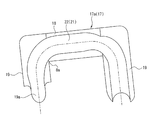
ナット14の周方向の側面の一部には平坦面14aが形成されており、該平坦面14aには内部にボール循環経路21(図3参照)を有する循環部品17が押え具24を介して止めねじ23等によって取り付けられている。
該循環部品17は、ねじ軸12の軸方向に対して略直角方向に延びる柱状又はブロック状等の一対の脚部19と、一対の脚部19を接続する本体18とを備えている。
A
The
この循環部品17は、図3に示すように、例えばボール循環経路21の略経路方向に沿って点対称で2つに分割された分割体17aを分割面で互いに接合して構成され、分割体17aの分割面にはボール循環経路21を構成する循環溝22が形成されている。これにより、循環部品17は樹脂の射出成型等で容易に大量生産可能に形状になっている。
一対の脚部19は、ねじ軸12の軸方向に互いに離間し、且つねじ軸12の径方向に互いに離間して配置されている。
As shown in FIG. 3, the circulating
The pair of
各脚部19内のボール循環経路21の先端には、両ねじ溝11,13間の螺旋軌道を転動するボール15をねじ溝11の接線方向で、且つ両ねじ溝11,13のリード角と略一致する方向に掬い上げるタング部19aが設けられている。
これらの脚部19は前記両ねじ溝11,13間の螺旋軌道に連通してナット14の平坦面14aにねじ軸12の軸線に対して略直交する方向に穿孔された一対の円形又は長円形状の循環孔20に嵌合されている。
At the tip of the
These
そして、この循環部品17によって、前記両ねじ溝11,13間の螺旋軌道を転動するボール15を一方の脚部19から掬い上げてナット14外部の本体18内に導き、他方の脚部19から前記螺旋軌道に戻すボールの無限循環軌道を形成している。
この循環部品17が図12に示す従来のボールねじ装置に用いられるチューブ式の循環部品8と異なる点としては、一対の脚部19をナット14の平坦面14aに形成した循環孔20にほとんど隙間なく、単純にはめ込みながら、脚部19の内部のボール循環経路21の方向を循環孔20の軸線に対して傾けることが可能な点である。
Then, by this circulating
The circulating
このため、ナット14の平坦面14aには、従来のボールねじ装置のように、ねじ軸12の軸線に対して略垂直方向に循環孔20を加工しておき、この循環孔20に単純に循環部品17の脚部19をはめ込む構造としながら、脚部19内に形成したボール循環経路21内のボール15の進行方向をねじ溝11の接線方向で、且つ両ねじ溝11,13のリード角方向と略一致する方向に傾けることが可能となる。
For this reason, a circulating
これにより、ナット14の加工が簡単で、且つボール15のすくい上げ通路の設計的自由度の向上を図ることができる。
ところで、上述したように、循環部品17のボール循環経路21内でのボール15の方向変換時のスムースな転動を確保して該ボール循環経路21内の摩耗等を防止するためには、ボール循環経路21の湾曲部の曲げR寸法を極力大きくする必要がある。
Thereby, the process of the
By the way, as described above, in order to ensure smooth rolling at the time of changing the direction of the
この場合、何の対策も施さないと、図4に示すように、循環部品17のボール循環経路21の内周側における脚部19と本体18との間の隅肉部8aの肉厚が局部的に薄くなり、この薄肉部分に応力集中しやすくなって循環部品17の強度が低下してしまうほか、循環部品17を樹脂の射出成形にて製作した場合には、肉厚が局部的に違うことから成形時の変形を招き、部品の形状精度が低下する問題が生じる。
In this case, if no measures are taken, as shown in FIG. 4, the thickness of the
そこで、この実施の形態では、図5及び図6に示すように、循環部品17のボール循環経路21の内周側における脚部19と本体18との間に増肉部30を設けることによって、循環部品17の強度低下や樹脂射出成形時の変形等を防止している。なお、増肉部30はR形状でもよいし、直線断面を持つ形状等でもよい。
また、循環部品17に前記増肉部30を設けた場合、循環部品17とナット14との干渉を確実に防止するためには、図7に示すように、ナット14側に増肉部30を逃げるための逃げ部40を設ける必要がある。
Therefore, in this embodiment, as shown in FIGS. 5 and 6, by providing a thickened
Further, when the thickening
この逃げ部40の形状例を図8に示す。
図8の例は、ナット14をエンドミルにて加工後、エンドミルを循環孔20のナット14の外周側の開口縁の一部に対して循環部品17の増肉部30の方向(図7のX−Xの方向)へと円弧状(図8(a)参照)や斜面状(図8(b)参照)、あるいは循環部品17の増肉部30の形状に沿って移動して加工(図示せず)することで、ナット14側に循環部品17の増肉部30に対応する逃げ部40を設けている。但し、このような加工方法はナット14の加工コストが割高になる傾向がある。
An example of the shape of the
In the example of FIG. 8, after the
図9及び図10を参照して、ナット14の加工コストを低く押えることができる逃げ部40の加工方法を説明する。
ここでは、循環部品17の増肉部30を逃げる逃げ部40を、循環孔20のナット14の外周側の開口縁の一部に該循環孔20の軸線と略同一方向から単純にざぐり加工を施すことにより形成している。
逃げ部40のざぐり形状例を図10に示す。
逃げ部40のざぐり形状は、図10(a)に示すような平面ざぐり形状でもよいし、図10(b)に示すような円錐穴のざぐり形状でもよく、あるいは図10(c)に示すようにボールエンドミルや特殊形状工具を用いてのざぐり形状や循環部品17の増肉部30の形状に沿ったざぐり形状(図示せず)としてもよい。また、図示は省略するが、ザグリ工具の形状は円錐台形状等でもよい。
With reference to FIG.9 and FIG.10, the processing method of the
Here, the
An example of a counterbore shape of the
The counterbore shape of the
このように、循環孔20のナット14の外周側の開口縁の一部に該循環孔20の軸線と略同一方向から単純にざぐり加工を施すことにより、容易に且つ低コストで循環部品17の増肉部30を逃げるための逃げ部40をナット14に加工することができる。
このようにこの実施の形態では、循環部品17のボール循環経路21の内周側における脚部19と本体18との間に増肉部30を設けているので、循環部品17の大型化を招くことなく、ボール循環経路21の曲げR寸法を大きくすることができると共に、循環部品17の強度低下や樹脂射出成形時の変形等を防止することができる。
In this way, a part of the opening edge on the outer peripheral side of the
Thus, in this embodiment, since the thickened
また、循環孔20のナット14の外周側の開口縁の一部に循環部品17の増肉部30に対応する逃げ部40を設けているので、循環部品17の増肉部30とナット14との干渉を確実に防止することができる。
更に、前記逃げ部40を、循環孔20のナット14の外周側の開口縁の一部に該循環孔20の軸線と略同一方向からざぐり加工を施して形成することで、ナット14側の加工コストを最小限に押えることができる。
Further, since the
Further, the
更に、循環部品17の脚部19内のボール循環経路21が循環孔20の軸線に対して傾斜して形成されているので、略接線方向で、且つ略リード角方向のボール15のすくい上げを容易に実現することができる。
なお、本発明は上記実施の形態に限定されるものではなく、本発明の要旨を逸脱しない範囲において適宜変更可能である。
例えば、上記実施の形態では、循環部品17を押え具24を介してナット14の平坦面14aに固定しているが、押え具24を用いずに循環部品17をナット14の平坦面14aに止めねじ等によって直接固定してもよい。
Further, since the
In addition, this invention is not limited to the said embodiment, In the range which does not deviate from the summary of this invention, it can change suitably.
For example, in the above embodiment, the circulating
また、前記螺旋軌道を転動する多数のボール15の各ボール15間に、駆動時のボール同士の衝突や接触を無くしてボール15の損傷防止や低騒音化を図るべく、図11に示すように、該ボール15に対向する両側面にそれぞれ円弧状の凹面を有する保持ピース100を介装してもよい。
なお、保持ピースは各ボール15間に個別に介装するタイプ、各保持ピースが互いに連結されたタイプのどちらでもよい。
その他、上記実施の形態において例示したねじ溝、ねじ軸、ナット、ボール、循環孔、ボール循環経路、循環部品、脚部、本体、増肉部、逃げ部、保持ピース等の材質,形状,寸法,形態,数,配置個所等は本発明を達成できるものであれば任意であり、限定されない。
Further, in order to prevent the
The holding piece may be either a type in which the holding pieces are interposed between the
In addition, the materials, shapes, and dimensions of the screw grooves, screw shafts, nuts, balls, circulation holes, ball circulation paths, circulation parts, legs, main bodies, thickened portions, relief portions, holding pieces, etc., exemplified in the above embodiment As long as the present invention can be achieved, the shape, number, location, etc. are arbitrary and are not limited.
10 ボールねじ装置
11 ねじ溝
12 ねじ軸
13 ねじ溝
14 ナット
15 ボール
17 循環部品
17a 分割体
18 本体
19 脚部
20 循環孔
21 ボール循環経路
30 増肉部
40 逃げ部
100 保持ピース
DESCRIPTION OF
Claims (6)
該循環部品が、前記ナットの前記循環孔に嵌合される一対の脚部と、該一対の脚部を接続する本体とを具備するボールねじ装置において、
前記循環部品の前記ボール循環経路の内周側における前記脚部と前記本体との間に増肉部を設けたことを特徴とするボールねじ装置。 A screw shaft having a spiral thread groove on the outer peripheral surface, a nut having a spiral thread groove corresponding to the screw groove of the screw shaft on the inner peripheral surface and screwed onto the screw shaft; A large number of balls loaded so as to be able to roll on the spiral track between the thread grooves and the balls rolling on the spiral track in a direction substantially perpendicular to the axis of the nut on the circumferential side surface of the nut. One end of each of the pair of drilled holes is led to the outside of the nut, and both ends are fitted to each of the circulation holes so as to form a ball circulation path to return to the spiral track from the other circulation hole. With combined circulation parts,
In the ball screw device, wherein the circulating component includes a pair of legs fitted into the circulation hole of the nut, and a main body connecting the pair of legs.
A ball screw device characterized in that a thickened portion is provided between the leg portion and the main body on the inner peripheral side of the ball circulation path of the circulating component.
Priority Applications (1)
| Application Number | Priority Date | Filing Date | Title |
|---|---|---|---|
| JP2004317288A JP2006125580A (en) | 2004-10-29 | 2004-10-29 | Ball screw device |
Applications Claiming Priority (1)
| Application Number | Priority Date | Filing Date | Title |
|---|---|---|---|
| JP2004317288A JP2006125580A (en) | 2004-10-29 | 2004-10-29 | Ball screw device |
Publications (1)
| Publication Number | Publication Date |
|---|---|
| JP2006125580A true JP2006125580A (en) | 2006-05-18 |
Family
ID=36720505
Family Applications (1)
| Application Number | Title | Priority Date | Filing Date |
|---|---|---|---|
| JP2004317288A Withdrawn JP2006125580A (en) | 2004-10-29 | 2004-10-29 | Ball screw device |
Country Status (1)
| Country | Link |
|---|---|
| JP (1) | JP2006125580A (en) |
Cited By (3)
| Publication number | Priority date | Publication date | Assignee | Title |
|---|---|---|---|---|
| JP2011236963A (en) * | 2010-05-10 | 2011-11-24 | Nsk Ltd | Using method of ball screw |
| JP2012137154A (en) * | 2010-12-27 | 2012-07-19 | Nsk Ltd | Ball screw circulation part and ball screw |
| CN113490804A (en) * | 2019-02-28 | 2021-10-08 | 株式会社万都 | Ball return tube for ball nut assembly |
-
2004
- 2004-10-29 JP JP2004317288A patent/JP2006125580A/en not_active Withdrawn
Cited By (4)
| Publication number | Priority date | Publication date | Assignee | Title |
|---|---|---|---|---|
| JP2011236963A (en) * | 2010-05-10 | 2011-11-24 | Nsk Ltd | Using method of ball screw |
| JP2012137154A (en) * | 2010-12-27 | 2012-07-19 | Nsk Ltd | Ball screw circulation part and ball screw |
| CN113490804A (en) * | 2019-02-28 | 2021-10-08 | 株式会社万都 | Ball return tube for ball nut assembly |
| CN113490804B (en) * | 2019-02-28 | 2024-03-29 | 汉拿万都株式会社 | Ball return pipe of ball nut assembly |
Similar Documents
| Publication | Publication Date | Title |
|---|---|---|
| EP1515066A2 (en) | Ball screw apparatus | |
| JP5500268B2 (en) | Ball screw device | |
| JP5637218B2 (en) | Ball screw device | |
| JP6693264B2 (en) | Ball screw | |
| JP2005299754A (en) | Screw device and its manufacturing method | |
| JP2009138914A (en) | Ball screw unit | |
| JP2006046530A (en) | Ball screw device | |
| WO2018066664A1 (en) | Circulation component retainer and ball screw | |
| JP2006125580A (en) | Ball screw device | |
| JP2003113922A (en) | Ball screw apparatus | |
| WO2006126452A1 (en) | Ball screw and movement guiding device | |
| JP2012112432A (en) | Return tube, method of manufacturing the same and ball screw | |
| JP6103007B2 (en) | Method for manufacturing ball screw device | |
| JP2005083519A (en) | Ball screw device | |
| WO2009084164A1 (en) | Ball screw device | |
| JP2007211969A (en) | Return tube and ball screw | |
| KR100559395B1 (en) | Micro boring bearing | |
| JP2005083522A (en) | Ball screw device | |
| JP2005030489A (en) | Ball screw device | |
| JP2005351340A (en) | Ball screw device | |
| JP2006300166A (en) | Ball screw device | |
| JP2005083520A (en) | Ball screw device | |
| JP2006002923A (en) | Ball screw device | |
| JP4931779B2 (en) | End cap type ball screw | |
| JP2010014236A (en) | Ball screw |
Legal Events
| Date | Code | Title | Description |
|---|---|---|---|
| A621 | Written request for application examination |
Free format text: JAPANESE INTERMEDIATE CODE: A621 Effective date: 20070411 |
|
| A761 | Written withdrawal of application |
Free format text: JAPANESE INTERMEDIATE CODE: A761 Effective date: 20080903 |