JP2006114450A - Plasma generating device - Google Patents
Plasma generating device Download PDFInfo
- Publication number
- JP2006114450A JP2006114450A JP2004303240A JP2004303240A JP2006114450A JP 2006114450 A JP2006114450 A JP 2006114450A JP 2004303240 A JP2004303240 A JP 2004303240A JP 2004303240 A JP2004303240 A JP 2004303240A JP 2006114450 A JP2006114450 A JP 2006114450A
- Authority
- JP
- Japan
- Prior art keywords
- electrode
- plasma
- discharge
- rod
- cylindrical
- Prior art date
- Legal status (The legal status is an assumption and is not a legal conclusion. Google has not performed a legal analysis and makes no representation as to the accuracy of the status listed.)
- Pending
Links
- 229910000575 Ir alloy Inorganic materials 0.000 claims description 4
- WFKWXMTUELFFGS-UHFFFAOYSA-N tungsten Chemical group [W] WFKWXMTUELFFGS-UHFFFAOYSA-N 0.000 claims description 4
- 239000010937 tungsten Substances 0.000 claims description 4
- 229910052721 tungsten Inorganic materials 0.000 claims description 4
- 238000010891 electric arc Methods 0.000 abstract description 13
- 238000010586 diagram Methods 0.000 description 13
- 239000010935 stainless steel Substances 0.000 description 11
- 229910001220 stainless steel Inorganic materials 0.000 description 11
- 230000000694 effects Effects 0.000 description 10
- 238000002347 injection Methods 0.000 description 9
- 239000007924 injection Substances 0.000 description 9
- 239000012212 insulator Substances 0.000 description 6
- 238000004519 manufacturing process Methods 0.000 description 6
- 239000004743 Polypropylene Substances 0.000 description 5
- 230000005684 electric field Effects 0.000 description 5
- 238000007788 roughening Methods 0.000 description 4
- NIXOWILDQLNWCW-UHFFFAOYSA-N acrylic acid group Chemical group C(C=C)(=O)O NIXOWILDQLNWCW-UHFFFAOYSA-N 0.000 description 3
- 238000000354 decomposition reaction Methods 0.000 description 3
- 239000000463 material Substances 0.000 description 3
- 229910052751 metal Inorganic materials 0.000 description 3
- 239000002184 metal Substances 0.000 description 3
- 238000000034 method Methods 0.000 description 3
- 229910052754 neon Inorganic materials 0.000 description 3
- GKAOGPIIYCISHV-UHFFFAOYSA-N neon atom Chemical compound [Ne] GKAOGPIIYCISHV-UHFFFAOYSA-N 0.000 description 3
- 239000011347 resin Substances 0.000 description 3
- 229920005989 resin Polymers 0.000 description 3
- 238000004090 dissolution Methods 0.000 description 2
- 230000000149 penetrating effect Effects 0.000 description 2
- 230000001681 protective effect Effects 0.000 description 2
- 239000000853 adhesive Substances 0.000 description 1
- 229910052782 aluminium Inorganic materials 0.000 description 1
- XAGFODPZIPBFFR-UHFFFAOYSA-N aluminium Chemical compound [Al] XAGFODPZIPBFFR-UHFFFAOYSA-N 0.000 description 1
- 239000011248 coating agent Substances 0.000 description 1
- 238000000576 coating method Methods 0.000 description 1
- 239000012141 concentrate Substances 0.000 description 1
- 238000007599 discharging Methods 0.000 description 1
- 238000000605 extraction Methods 0.000 description 1
- 239000011888 foil Substances 0.000 description 1
- 238000009434 installation Methods 0.000 description 1
- 150000002500 ions Chemical class 0.000 description 1
- 238000002844 melting Methods 0.000 description 1
- 230000008018 melting Effects 0.000 description 1
- 230000004048 modification Effects 0.000 description 1
- 238000012986 modification Methods 0.000 description 1
- -1 polypropylene Polymers 0.000 description 1
- 229920001155 polypropylene Polymers 0.000 description 1
Images


Classifications
-
- H—ELECTRICITY
- H05—ELECTRIC TECHNIQUES NOT OTHERWISE PROVIDED FOR
- H05H—PLASMA TECHNIQUE; PRODUCTION OF ACCELERATED ELECTRICALLY-CHARGED PARTICLES OR OF NEUTRONS; PRODUCTION OR ACCELERATION OF NEUTRAL MOLECULAR OR ATOMIC BEAMS
- H05H1/00—Generating plasma; Handling plasma
- H05H1/24—Generating plasma
- H05H1/52—Generating plasma using exploding wires or spark gaps
-
- H—ELECTRICITY
- H05—ELECTRIC TECHNIQUES NOT OTHERWISE PROVIDED FOR
- H05H—PLASMA TECHNIQUE; PRODUCTION OF ACCELERATED ELECTRICALLY-CHARGED PARTICLES OR OF NEUTRONS; PRODUCTION OR ACCELERATION OF NEUTRAL MOLECULAR OR ATOMIC BEAMS
- H05H1/00—Generating plasma; Handling plasma
- H05H1/24—Generating plasma
- H05H1/47—Generating plasma using corona discharges
- H05H1/473—Cylindrical electrodes, e.g. rotary drums
Landscapes
- Physics & Mathematics (AREA)
- Engineering & Computer Science (AREA)
- Plasma & Fusion (AREA)
- Spectroscopy & Molecular Physics (AREA)
- Plasma Technology (AREA)
Abstract
Description
本発明は、密閉された真空環境などではなく、大気圧の環境下でプラズマを生成するプラズマ生成装置に関する。 The present invention relates to a plasma generating apparatus that generates plasma in an atmosphere of atmospheric pressure, not in a sealed vacuum environment.
最近、大気圧の環境下でプラズマを生成する要望が増えてきている。このプラズマによれば、たとえば対象物の表面を改質したりすることが可能である。 Recently, there has been an increasing demand for generating plasma in an atmospheric pressure environment. According to this plasma, for example, the surface of an object can be modified.
このような表面改質の用途の一例として、たとえばポリプロピレン(以下「PP」という)に対して印刷を施したい場合があるが、通常PPの表面は非常に滑らかでインクがうまくのらない状態であり、これを改善するためにプラズマによって表面状態を故意に荒らして、その上から印刷可能にする用途が知られている。 As an example of such surface modification applications, for example, there is a case where it is desired to print on polypropylene (hereinafter referred to as “PP”), but the surface of PP is usually very smooth and the ink does not work well. In order to improve this, there is known an application in which the surface state is intentionally roughened by plasma and printing is possible from above.
また、対象物の表面を荒らすことによって、そこに接着剤を塗布して接着する際の接着性を向上することもできる。 Moreover, the adhesiveness at the time of apply | coating an adhesive agent there and adhere | attaching can also be improved by roughening the surface of a target object.
ところで、プラズマを生成する方法としては放電を利用することがよく知られている。たとえば特許文献1にはその一例が開示されている。 By the way, it is well known that discharge is used as a method for generating plasma. For example, Patent Document 1 discloses an example thereof.
特許文献1に記載の発明では、スタッド形状の電極とその周囲を覆うケーシング(接地電位)との間でアーク放電を発生させ、この放電路に対して作動ガスを吹き込ませて、その作動ガスのプラズマを発生させる技術について開示している。 In the invention described in Patent Document 1, an arc discharge is generated between a stud-shaped electrode and a casing (ground potential) covering the periphery thereof, and a working gas is blown into the discharge path, so that the working gas A technique for generating plasma is disclosed.
特許文献1に記載の発明のように、従来のプラズマ生成装置では、電極間にアーク放電を発生させ、その熱によって作動ガスを分解しプラズマを生成するようにしていた。 As in the invention described in Patent Document 1, in the conventional plasma generator, arc discharge is generated between the electrodes, and the working gas is decomposed by the heat to generate plasma.
ところが、従来のように、作動ガス分解のためにアーク放電を用いる場合には、高電圧を必要とし、消費電力量が大きく、熱で作動ガスを分解するため余分なエネルギーを浪費してしまうし、プラズマ生成のために多くの熱量を発生し、経時的な電極溶解の進行も早いという問題があった。 However, when arc discharge is used for working gas decomposition as in the prior art, a high voltage is required, power consumption is large, and the working gas is decomposed by heat, so that extra energy is wasted. However, there is a problem that a large amount of heat is generated for plasma generation, and the electrode dissolution progresses with time.
本発明は上記の点にかんがみてなされたもので、アーク放電を発生させずに、大気圧下で効率良くプラズマを生成することができるプラズマ生成装置を提供することを目的とする。 The present invention has been made in view of the above points, and an object of the present invention is to provide a plasma generating apparatus capable of generating plasma efficiently under atmospheric pressure without generating arc discharge.
本発明は上記課題を解決するため、第1の電極と、第2の電極と、パルス電圧を発生するパルス電源とを有し、前記第1の電極と前記第2の電極との間に前記パルス電源による所定のパルス電圧を印加することによって、前記第1の電極と前記第2の電極との間に放電を発生させ、該放電によってプラズマを生成することを特徴とする。 In order to solve the above-described problem, the present invention includes a first electrode, a second electrode, and a pulse power source that generates a pulse voltage, and the gap is between the first electrode and the second electrode. By applying a predetermined pulse voltage from a pulse power source, a discharge is generated between the first electrode and the second electrode, and plasma is generated by the discharge.
また本発明は、前記第1の電極が電極棒であり、前記第2の電極が円筒電極であり、前記円筒電極の中心に前記電極棒を設け、同軸円筒形状を形成することを特徴とする。 Further, the present invention is characterized in that the first electrode is an electrode rod, the second electrode is a cylindrical electrode, the electrode rod is provided at the center of the cylindrical electrode, and a coaxial cylindrical shape is formed. .
また本発明は、前記第1の電極が電極棒であり、前記第2の電極が電極板であり、前記電極棒の先端を所定の距離だけ離して前記電極板の面に向けて配置することを特徴とする。 According to the present invention, the first electrode is an electrode rod, the second electrode is an electrode plate, and the tip of the electrode rod is arranged at a predetermined distance toward the surface of the electrode plate. It is characterized by.
本発明によれば、アーク放電を必要とせずに、大気圧下で効率良くプラズマを生成することができるプラズマ生成装置を提供することができる。 ADVANTAGE OF THE INVENTION According to this invention, the plasma production | generation apparatus which can produce | generate a plasma efficiently under atmospheric pressure can be provided, without requiring arc discharge.
すなわち本発明によれば、従来のように作動ガス分解のために(大電流を必要とする)アーク放電を用いないので、消費電力量が小さいという効果を奏することができる。また、熱で作動ガスを分解しないので余分なエネルギー浪費がないし、プラズマ生成のために多くの熱量を発生することもないし、電極溶解のおそれもない。 That is, according to the present invention, since arc discharge (requiring a large current) is not used for working gas decomposition as in the prior art, an effect that power consumption is small can be achieved. Further, since the working gas is not decomposed by heat, there is no extra energy wasted, no large amount of heat is generated for plasma generation, and there is no fear of electrode dissolution.
本発明によれば、火花放電で生成された電子で作動ガスを分解しプラズマを生成するため、従来のようなアークによる余分な熱エネルギーの浪費がない。 According to the present invention, since the working gas is decomposed by the electrons generated by the spark discharge to generate the plasma, there is no wasted heat energy due to the arc as in the prior art.
また本発明によれば、同軸円筒電極効果によって放電効果を高めることができ、低い放電電圧であってもプラズマ生成のための放電路を形成することができる。 Further, according to the present invention, the discharge effect can be enhanced by the coaxial cylindrical electrode effect, and a discharge path for plasma generation can be formed even at a low discharge voltage.
また本発明によれば、電極にパルス電圧を印加するようにしたので、連続放電のアーク放電になってしまわないようにすることができ、グローコロナ放電や火花放電により、消費電力量を少なくすることができる。 Further, according to the present invention, since a pulse voltage is applied to the electrodes, it is possible to prevent arc discharge of continuous discharge and to reduce power consumption by glow corona discharge and spark discharge. be able to.
また本発明によれば、プラズマ生成のための作動ガスの分解において、電子と気体(作動ガス)との衝突によってその気体を電離するので、熱をほとんど発生しないで済む。 Further, according to the present invention, in the decomposition of the working gas for generating plasma, the gas is ionized by collision of electrons and gas (working gas), so that almost no heat is generated.
また本発明によれば、電極にパルス電圧を印加するようにしたので、連続放電のアーク放電になってしまわないようにすることができ、グローコロナ放電や火花放電により、熱の発生が少ないので電極の熔解はない。 In addition, according to the present invention, since a pulse voltage is applied to the electrodes, it is possible to prevent arc discharge of continuous discharge, and less heat is generated by glow corona discharge or spark discharge. There is no electrode melting.
以下、本発明の実施の形態について図面を参照して詳細に説明する。 Hereinafter, embodiments of the present invention will be described in detail with reference to the drawings.
図1は、本発明の一実施の形態によるプラズマ生成装置の構成を示す概略断面ブロック図である。 FIG. 1 is a schematic cross-sectional block diagram showing the configuration of a plasma generating apparatus according to an embodiment of the present invention.
電極棒1はたとえば直径0.6mmのイリジウム合金、タングステンまたはステンレス等の棒であり、円筒電極2はたとえば内径4.3mmの円筒形状のステンレス管である。
The electrode rod 1 is a rod of iridium alloy, tungsten, stainless steel or the like having a diameter of 0.6 mm, for example, and the
ケーシング4はたとえば内径10mmの円筒管であり、その材質は各電極から絶縁されていればSUS(ステンレス)などの金属でもよいし、アクリルなどの樹脂であってもよい。
The
底部材5は、円筒管であるケーシング4の内側に嵌る円板状の部材であり、電極棒1およびガス注入管15を貫通させるための穴が設けられている。この底部材5は絶縁物で形成されている。
The
支持部材7は、底部材5と同様に円筒管であるケーシング4の内側に嵌るとともに、支持部材7の内側には円筒電極2が嵌めこまれる形状に形成されている。また、この支持部材7には貫通する複数の穴8が設けられている。
The support member 7 is formed in a shape in which the
ガスボンベ14から注入された作動ガスはこの穴8を通過するが、その後のガスの流れがスパイラル状ガス流16となるようにすなわち回転しながら前方に向かうように、図1に示すよう斜めに穴8を形成してある。
The working gas injected from the
支持部材7には電極棒1を貫通させるための穴がさらに設けられている。この支持部材7も絶縁物で形成されている。 The support member 7 is further provided with a hole for allowing the electrode rod 1 to pass therethrough. This support member 7 is also formed of an insulator.
ガスポンベ14からの作動ガスは、ガス注入管15を介してケーシング4内に注入される。なお、本実施の形態ではガスボンベとしたが、本発明はこれに限られるものではなく、作動ガスであるエアーを送りこむエアーポンプのようなものでもかまわない。
The working gas from the
電極棒1は、底部材5および支持部材7を貫通し、この底部材5および支持部材7によって支持される。
The electrode rod 1 passes through the
一方、円筒電極2は支持部材7の内側に嵌めこまれ、この支持部材7によって、電極棒1と円筒電極2との位置決めがされる。すなわち、円筒電極2の中心に電極棒1を設け、同軸円筒形状を形成する。
On the other hand, the
本実施の形態においては、支持部材9およびプラズマ加速用の電極板3がさらに設けられ、円筒電極2の一端は支持部材9の内側に嵌めこまれており、支持部材9の内側にはさらに電極板3が嵌めこまれている。電極板3はたとえばステンレス製であり、支持部材9は絶縁物で形成されている。
In the present embodiment, a
電極板3には、加速されたプラズマ17が貫通する穴3aが設けられている。この穴の直径はたとえば2mm以上である。
The
本実施の形態では、円筒電極2は接地13に接続され、電極棒1には抵抗10(安定抵抗、保護抵抗)を介してパルス電源11によるパルス電圧が印加され、この電極棒1と円筒電極2との間にグローコロナ放電、火花放電が発生する。パルス電源の代わりに高周波電源(インバータネオントランス)を用いてもよい。
In the present embodiment, the
パルス電源11からのパルス電圧の一例としては、電圧波形が1/2サイン波で、パルス幅τ=16μsecで、周波数f=0.7〜0.8kHzで、放電電圧値Vd=2.5kVとすることができる。また、放電電流Id=0.021Aで、抵抗10の抵抗値r=140kΩとすることができる。
As an example of the pulse voltage from the
このように電極棒1と円筒電極2との間に放電電圧が印加され、放電が発生している状態のときに、ガスボンベ14からガス注入管15を介して作動ガスを注入すると、穴8を通過したガスがスパイラル状ガス流16を生じ、このガス流16が電極棒1と円筒電極2との間に生じた火花放電路6を先端に噴出するように湾曲させ、またこの湾曲させられた火花放電路6を通過する際に作動ガスはプラズマ化される。
When a discharge voltage is applied between the electrode rod 1 and the
電極板3には直流電源12による直流電圧が印加され、火花放電路6の領域にて生成されたプラズマ中の電子を引き出す効果を有する。この電子は、ガスボンベ14によるガス流16の噴出の勢いおよび電極板3による引出し効果によって穴3aから射出され、これがプラズマトーチ17となる。
A direct current voltage from a direct
プラズマトーチ17の利用方法の一例としては、前述のようにPP等の表面荒らしとして用いることができる。
As an example of a method of using the
なお、本実施の形態において、図1に示す円筒電極2と電極板3との距離dは、火花放電路6が電極板3に達しない程度で、任意に定めることができる。
In the present embodiment, the distance d between the
本実施の形態では、アーク放電を防ぐため、電極棒1と円筒電極2の電極間にパルス電圧を印加するとともに、安定抵抗として機能する抵抗10を挿入し、大気圧中のグローコロナ放電、火花放電を実現している。すなわち、電源にパルス電源(または高周波電源(インバータネオントランス))を用いることによって、連続放電によるアーク放電を防ぐようにしている。
In the present embodiment, in order to prevent arc discharge, a pulse voltage is applied between the electrode rod 1 and the
ここで、図1に示した実施の形態での電極棒1および円筒電極による同軸円筒効果について説明する。 Here, the coaxial cylindrical effect by the electrode rod 1 and the cylindrical electrode in the embodiment shown in FIG. 1 will be described.
図2は、図1に示したプラズマ生成装置の同軸円筒効果について説明する図である。 FIG. 2 is a diagram for explaining the coaxial cylindrical effect of the plasma generating apparatus shown in FIG.
図2に示すように、電極棒1の半径をaとし、円筒電極2の内面の半径をbとし、パルス電源11の電圧をVdとし、抵抗10の抵抗値をrとしたとき、電極棒1と円筒電極2との間に生じる電界Eは数1で表される。
As shown in FIG. 2, when the radius of the electrode rod 1 is a, the radius of the inner surface of the
![]()
![]()
次に、本発明の図1とは別の実施の形態について説明する。 Next, an embodiment different from FIG. 1 of the present invention will be described.
図3は、本発明の別の実施の形態によるプラズマ生成装置の構成を示す概略断面ブロック図である。 FIG. 3 is a schematic cross-sectional block diagram showing a configuration of a plasma generating apparatus according to another embodiment of the present invention.
この図3に示す実施の形態のプラズマ生成装置は、図1のプラズマ生成装置における電極板3、支持部材9および直流電源12に相当する構成を有さないものとなっている。
The plasma generating apparatus of the embodiment shown in FIG. 3 does not have a configuration corresponding to the
以下に図3のプラズマ生成装置の構成について説明する。 Hereinafter, the configuration of the plasma generation apparatus of FIG. 3 will be described.
電極棒101はたとえば直径0.6mmのイリジウム合金、タングステンまたはステンレス等の棒であり、円筒電極102はたとえば内径4.3mmの円筒形状のステンレス管である。
The
ケーシング104はたとえば内径10mmの円筒管であり、その材質はSUS(ステンレス)などの金属でもよいし、アクリルなどの樹脂であってもよい。
The
底部材105は、円筒管であるケーシング104の内側に嵌る円板状の部材であり、電極棒101およびガス注入管115を貫通させるための穴が設けられている。この底部材5は絶縁物で形成されている。
The
支持部材107は、底部材105と同様に円筒管であるケーシング104の内側に嵌るとともに、支持部材107の内側には円筒電極102が嵌めこまれる形状に形成されている。また、この支持部材107には貫通する複数の穴108が設けられている。
Similarly to the
ガスボンベ114から注入された作動ガスはこの穴108を通過するが、その後のガスの流れがスパイラル状ガス流116となるようにすなわち回転しながら前方に向かうように、図3に示すよう斜めに穴108を形成してある。
The working gas injected from the
支持部材107には電極棒101を貫通させるための穴がさらに設けられている。この支持部材107も絶縁物で形成されている。
The
ガスポンベ114からの作動ガスは、ガス注入管115を介してケーシング104内に注入される。
The working gas from the
電極棒101は、底部材105および支持部材107を貫通し、この底部材105および支持部材107によって支持される。
The
一方、円筒電極102は支持部材107の内側に嵌めこまれ、この支持部材107によって、電極棒101と円筒電極102との位置決めがされる。
On the other hand, the
本実施の形態では、図1の実施の形態と異なり、円筒電極2の先端が露出し、火花放電路106が外部に噴出される構成となっており、この火花放電路106がプラズマトーチとなる。前述のようにPP等の表面荒らしをしたい場合には、表面荒らしをしたい対象物に対して円筒電極2の先端を向け、その対象物に火花放電路106が接触するようにすればよい。
In the present embodiment, unlike the embodiment of FIG. 1, the tip of the
円筒電極102は接地113に接続され、電極棒101には抵抗110(安定抵抗、保護抵抗)を介してパルス電源111によるパルス電圧が印加され、この電極棒101と円筒電極102との間にグローコロナ放電、火花放電が発生する。
The
電極棒101と円筒電極102との間に放電電圧が印加され、放電が発生している状態のときに、ガスボンベ114からガス注入管115を介して作動ガスを注入すると、穴108を通過したガスがスパイラル状ガス流116を生じ、このガス流116が電極棒101と円筒電極102との間に生じた火花放電路106を先端に噴出するように湾曲させ、またこの湾曲させられた火花放電路106を通過する際に作動ガスはプラズマ化される。
When a discharge voltage is applied between the
本実施の形態においても、アーク放電を防ぐため、電極棒101と円筒電極102の電極間にパルス電圧を印加するとともに、安定抵抗として機能する抵抗110を挿入し、大気圧中のグローコロナ放電、火花放電を実現している。
Also in this embodiment, in order to prevent arc discharge, a pulse voltage is applied between the electrodes of the
この図3に示す実施の形態においてそのほかの点については、図1に示した実施の形態と同様であるので、さらなる説明は省略する。 Since the other points in the embodiment shown in FIG. 3 are the same as those in the embodiment shown in FIG. 1, further description is omitted.
次に、本発明のさらに別の実施の形態について説明する。 Next, still another embodiment of the present invention will be described.
図4は、本発明のさらに別の実施の形態によるプラズマ生成装置の構成を示す概略断面ブロック図である。 FIG. 4 is a schematic cross-sectional block diagram showing a configuration of a plasma generating apparatus according to still another embodiment of the present invention.
この図4に示す実施の形態のプラズマ生成装置は、図1や図3に示した実施の形態とは異なり、同軸円筒電極を用いるのではなく、電極棒と平板電極との間に放電を生じさせる構成にて、複数の電極棒を設けるようにしている。 Unlike the embodiment shown in FIGS. 1 and 3, the plasma generator of the embodiment shown in FIG. 4 does not use a coaxial cylindrical electrode, but generates a discharge between the electrode rod and the plate electrode. In such a configuration, a plurality of electrode rods are provided.
電極棒205はたとえば直径0.6mm〜1mmのイリジウム合金、タングステンまたはステンレス等の棒であり、電極板202はたとえばアルミ箔またはステンレス板等である。
The
ケーシング204はたとえば内径12mmの円筒管であり、その材質は各電極から絶縁されていればSUS(ステンレス)などの金属でもよいし、アクリルなどの樹脂であってもよい。
The
電極棒205はそれぞれ絶縁管201に覆われている。この絶縁管201としてはいわゆる「がいし」を用いることができる。
The electrode bars 205 are each covered with an insulating
電極板202は接地208に接続され、電極棒205にはパルス電源203によるパルス電圧が印加され、この電極棒205と電極板202との間に放電が発生する。パルス電源の代わりに高周波電源(インバータネオントランス)を用いてもよい。
The
パルス電源203からのパルス電圧の一例としては、パルス周波数f=2kHzで、放電電圧値Vd=9.8kVとし、電極棒205と電極板202との間の距離を7〜10mmとすることができる。このような放電電圧を印加すると、電極棒205と電極板202との間に放電路206が形成され、プラズマが生成される。
As an example of the pulse voltage from the
電極板202の上には、図4に示すように、表面を荒らしたい対象物207を置く。このとき、荒らし対面が上側すなわち電極棒205側になるようにする。
On the
上述のように、電極棒205と電極板202との間にパルス電源203によって高電圧パルスを印加すると、電極間にグロー放電を生じ、電極棒205の近傍は電気力線が集中して高電界となり、高密度のプラズマが生成される。
As described above, when a high voltage pulse is applied between the
このとき、電極棒205を正極にすると、プラズマ中のイオンは電極板205の方向に加速され、電極板202の上に置かれた対象物207をスパッタすることができる。なお、生成するプラズマの密度は放電電流で制御し、放電間隔は放電電圧で制御する。
At this time, when the
印加電圧は高電圧で、放電電流は低電流であることが望ましい。また、電源にパルス電源を用いることによって、連続放電によるアーク放電を防ぐことができる。 It is desirable that the applied voltage is a high voltage and the discharge current is a low current. Further, by using a pulse power source as the power source, arc discharge due to continuous discharge can be prevented.
本実施の形態によれば、図1や図3の実施の形態のように作動ガスをポンプ等によって送りこみ、その勢いでプラズマを前方に噴出する必要がないので、ポンプ等を備える必要がないという効果がある。 According to the present embodiment, there is no need to provide a pump or the like because working gas is fed by a pump or the like as in the embodiment of FIG. 1 or FIG. There is an effect.
また、本実施の形態によれば、電極棒205を複数備えることによって、対象物207の面の広い領域に対して一度に面荒らしを行うことができ、広範囲にわたる処理をスムーズに行うことができるという効果がある。
Further, according to the present embodiment, by providing a plurality of electrode bars 205, it is possible to perform surface roughening at once on a wide area of the surface of the
なお、図4では複数の電極棒を備えているが、処理を施す面領域が狭くてもよいのであれば1本の電極棒でもよいことはいうまでもない。 Although a plurality of electrode bars are provided in FIG. 4, it goes without saying that a single electrode bar may be used if the surface area to be processed may be narrow.
次に、図4に示した実施の形態のように複数の電極棒を備える場合において、それぞれの設置の位置関係について説明する。 Next, in the case where a plurality of electrode bars are provided as in the embodiment shown in FIG. 4, the positional relationship of each installation will be described.
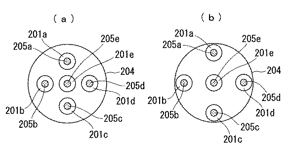
図5は、図3に示したプラズマ生成装置の電極棒の部分を見た底面図であり、(a)5本の電極棒を互いに近接して設けた場合を示す図であり、(b)は5本の電極棒を互いに離隔して設けた場合を示す図である。 FIG. 5 is a bottom view of the electrode rod portion of the plasma generating apparatus shown in FIG. 3, and (a) is a diagram showing a case where five electrode rods are provided close to each other, and (b) FIG. 5 is a view showing a case where five electrode rods are provided apart from each other.
図5(a)および図5(b)において、201a〜201eは絶縁管であり、205a〜205eは電極棒であり、204はケーシングである。 5A and 5B, 201a to 201e are insulating tubes, 205a to 205e are electrode bars, and 204 is a casing.
図5(a)に示すように複数の電極棒205a〜205eを互いに近接して設けた場合、中心の電極棒205eからの放電が行われないという状況が発生するおそれがある。中心の電極棒205eから放出される電子は、他の周囲の電極棒205a〜205dの放電によるローレンツ力によって、電極棒205eと垂直な方向すなわち電極板202と水平な方向に曲げられてしまう。このとき、電界も同様な方向に曲げられることになり、他の電極棒205a〜205eによる電界と反対方向になり、打ち消されてしまう。このため、中心の電極棒205eの近傍では放電が生じない状態もしくは弱い放電になってしまい、効率が悪くなるおそれがあった。
When a plurality of
そこで、本実施の形態では、この点についての対策を以下のように施した。 Therefore, in the present embodiment, measures for this point are taken as follows.
まず、第1の対策として、図5(b)に示すように複数の電極棒205a〜205eを互いに離隔して設けるようにした。
First, as a first countermeasure, a plurality of
このようにすることによって、中心の電極棒205eから放出される電子が、他の周囲の電極棒205a〜205dの放電による影響を、それほど受けなくすることができ、中心の電極棒205eの放電も生じさせることができる。
By doing so, the electrons emitted from the
また別の対策として、図6に示すようにすることも可能である。 As another countermeasure, it is also possible to make it as shown in FIG.
図6は、中心の電極棒からの放電が行われないため効率が悪いという問題に対する、図5(b)とは別の対策を示す図である。 FIG. 6 is a diagram showing a countermeasure different from FIG. 5B for the problem that the efficiency is low because no discharge from the central electrode rod is performed.
図6は、図4と同様にプラズマ発生装置を側面から見た図であり、電極棒205eが中心電極であり、電極棒205bおよび電極棒205dがその周囲の電極である。図6において、極棒205aおよび電極棒205cについて見やすさのため図示を省略してある。
FIG. 6 is a side view of the plasma generator as in FIG. 4, in which the
この図6に示す対策では、中心の電極棒205eを他の電極棒205a〜205dよりも長く(たとえば、電極棒の直径が1mm程度で、電極どうしの距離が4mm程度のとき、他の電極棒よりも2mm程度長く)し、他の電極棒205a〜205dの放電による影響を受け難くし、中心の電極棒205eの放電も生じさせることができるようにしている。
In the countermeasure shown in FIG. 6, the
さらに別の対策について図7を参照して説明する。 Still another countermeasure will be described with reference to FIG.
図7は、中心の電極棒からの放電が行われないため効率が悪いという問題に対する、図5(b)や図6とは別の対策を示す図である。この図7は、図5(b)と同様に、図3に示したプラズマ生成装置の電極棒の部分を見た底面図である。 FIG. 7 is a diagram showing a countermeasure different from that of FIG. 5B and FIG. 6 for the problem that the efficiency is low because no discharge from the central electrode rod is performed. FIG. 7 is a bottom view of the electrode rod portion of the plasma generating apparatus shown in FIG. 3 as in FIG. 5B.
この図7に示す対策では、中心電極である電極棒205eを初めから設けないようにし、中心電極で放電が行われないという問題を根本から解決するものである。
In the countermeasure shown in FIG. 7, the
次に、図1に示した実施の形態の応用例について説明する。 Next, an application example of the embodiment shown in FIG. 1 will be described.
図8は、図1に示した同軸円筒電極のプラズマ生成装置を複数備えて成るマルチ型のプラズマ生成装置の構成を示す概略断面ブロック図である。 FIG. 8 is a schematic cross-sectional block diagram showing a configuration of a multi-type plasma generation apparatus including a plurality of coaxial cylindrical electrode plasma generation apparatuses shown in FIG.
図8において、302a〜302cは円筒電極であり、301a〜301cは電極棒である。 In FIG. 8, 302a to 302c are cylindrical electrodes, and 301a to 301c are electrode bars.
この図8の例では、円筒電極302aと電極棒301aとの組み合わせ、円筒電極302bと電極棒301bとの組み合わせ、および円筒電極302cと電極棒301cとの組み合わせの3つのプラズマ生成装置を、ケーシング304に収納して構成される。
In the example of FIG. 8, three plasma generation apparatuses, which are a combination of a
ケーシング304の先端には、図1の電極板3に相当する電極部材303を備え、この電極部材303には、図1の穴3aに相当する穴303aが設けられている。
An
円筒電極302a〜302cは接地313に接続され、電極棒301a〜301cにはそれぞれパルス電源311a〜311cからパルス電圧が印加される。また、電極部材303には直流電源312から正電圧が印加される。
The
ケーシング4内にはガス注入管314を介して作動ガスが注入され、円筒電極302aと電極棒301aとの組み合わせ、円筒電極302bと電極棒301bとの組み合わせ、および円筒電極302cと電極棒301cとの組み合わせの3つのプラズマ生成装置によって生成されたプラズマは、電極部材303によって引き出され、穴303aから射出され、これがプラズマトーチとなる。
The working gas is injected into the
このようなマルチ型にすれば、放電電圧を増加させることなく、大容量のプラズマを生成することができる。 With such a multi-type, a large volume of plasma can be generated without increasing the discharge voltage.
1 電極棒
2 円筒電極
3 電極板
3a 穴
4 ケーシング
5 底部材
6 火花放電路
7 支持部材
8 ガス注入口
9 支持部材
10 抵抗
11 パルス電源
12 直流電源
13 接地
14 ガスボンベ
15 ガス注入管
16 スパイラル状ガス流
17 プラズマトーチ
DESCRIPTION OF SYMBOLS 1
Claims (12)
前記第1の電極と前記第2の電極との間に前記パルス電源による所定のパルス電圧を印加することによって、前記第1の電極と前記第2の電極との間に放電を発生させ、該放電によってプラズマを生成することを特徴とするプラズマ生成装置。 A first electrode, a second electrode, and a pulse power source for generating a pulse voltage;
By applying a predetermined pulse voltage from the pulse power source between the first electrode and the second electrode, a discharge is generated between the first electrode and the second electrode, A plasma generating apparatus that generates plasma by electric discharge.
前記第1の電極と前記第2の電極との間に前記高周波電源による所定の高周波電圧を印加することによって、前記第1の電極と前記第2の電極との間に放電を発生させ、該放電によってプラズマを生成することを特徴とするプラズマ生成装置。 A first electrode, a second electrode, and a high-frequency power source that generates a high-frequency voltage;
By applying a predetermined high-frequency voltage from the high-frequency power source between the first electrode and the second electrode, a discharge is generated between the first electrode and the second electrode, A plasma generating apparatus that generates plasma by electric discharge.
Priority Applications (3)
| Application Number | Priority Date | Filing Date | Title |
|---|---|---|---|
| JP2004303240A JP2006114450A (en) | 2004-10-18 | 2004-10-18 | Plasma generating device |
| US10/565,602 US20080050291A1 (en) | 2004-10-18 | 2005-10-05 | Plasma Generation Device |
| PCT/JP2005/018457 WO2006043420A1 (en) | 2004-10-18 | 2005-10-05 | Plasma generator |
Applications Claiming Priority (1)
| Application Number | Priority Date | Filing Date | Title |
|---|---|---|---|
| JP2004303240A JP2006114450A (en) | 2004-10-18 | 2004-10-18 | Plasma generating device |
Publications (2)
| Publication Number | Publication Date |
|---|---|
| JP2006114450A true JP2006114450A (en) | 2006-04-27 |
| JP2006114450A5 JP2006114450A5 (en) | 2007-11-22 |
Family
ID=36202839
Family Applications (1)
| Application Number | Title | Priority Date | Filing Date |
|---|---|---|---|
| JP2004303240A Pending JP2006114450A (en) | 2004-10-18 | 2004-10-18 | Plasma generating device |
Country Status (3)
| Country | Link |
|---|---|
| US (1) | US20080050291A1 (en) |
| JP (1) | JP2006114450A (en) |
| WO (1) | WO2006043420A1 (en) |
Cited By (18)
| Publication number | Priority date | Publication date | Assignee | Title |
|---|---|---|---|---|
| JP2006269095A (en) * | 2005-03-22 | 2006-10-05 | Takeshi Nagasawa | Plasma generation device |
| JP2009087697A (en) * | 2007-09-28 | 2009-04-23 | Masaru Hori | Plasma generator |
| WO2011065171A1 (en) * | 2009-11-27 | 2011-06-03 | 日本碍子株式会社 | Plasma processing device |
| CN102548176A (en) * | 2012-01-12 | 2012-07-04 | 北京交通大学 | Discharge electrode and plasma generating device using same |
| CN102595757A (en) * | 2012-03-19 | 2012-07-18 | 河北大学 | Three-electrode discharge device for generating large-volume atmosphere pressure plasma |
| JP2012522888A (en) * | 2009-04-02 | 2012-09-27 | ラインハウゼン・プラスマ・ゲゼルシャフト・ミト・ベシュレンクテル・ハフツング | Method and beam generator for generating a constrained plasma beam |
| JP2012528454A (en) * | 2008-05-30 | 2012-11-12 | コロラド ステート ユニバーシティー リサーチ ファウンデーション | Plasma device for wide-area surface treatment of tissue |
| JP2012531699A (en) * | 2009-06-29 | 2012-12-10 | ユニヴェルシテ ポール サバティエ トゥールーズ トロワ | A device that emits a plasma jet from ambient air at normal temperature and pressure, and its use |
| US9272359B2 (en) | 2008-05-30 | 2016-03-01 | Colorado State University Research Foundation | Liquid-gas interface plasma device |
| US9287091B2 (en) | 2008-05-30 | 2016-03-15 | Colorado State University Research Foundation | System and methods for plasma application |
| US9532826B2 (en) | 2013-03-06 | 2017-01-03 | Covidien Lp | System and method for sinus surgery |
| US9555145B2 (en) | 2013-03-13 | 2017-01-31 | Covidien Lp | System and method for biofilm remediation |
| US10368939B2 (en) | 2015-10-29 | 2019-08-06 | Covidien Lp | Non-stick coated electrosurgical instruments and method for manufacturing the same |
| US10441349B2 (en) | 2015-10-29 | 2019-10-15 | Covidien Lp | Non-stick coated electrosurgical instruments and method for manufacturing the same |
| US10709497B2 (en) | 2017-09-22 | 2020-07-14 | Covidien Lp | Electrosurgical tissue sealing device with non-stick coating |
| US10973569B2 (en) | 2017-09-22 | 2021-04-13 | Covidien Lp | Electrosurgical tissue sealing device with non-stick coating |
| US11207124B2 (en) | 2019-07-08 | 2021-12-28 | Covidien Lp | Electrosurgical system for use with non-stick coated electrodes |
| US11369427B2 (en) | 2019-12-17 | 2022-06-28 | Covidien Lp | System and method of manufacturing non-stick coated electrodes |
Families Citing this family (20)
| Publication number | Priority date | Publication date | Assignee | Title |
|---|---|---|---|---|
| JP5145076B2 (en) * | 2008-02-22 | 2013-02-13 | Nuエコ・エンジニアリング株式会社 | Plasma generator |
| DK2209354T3 (en) * | 2009-01-14 | 2014-07-14 | Reinhausen Plasma Gmbh | Beam generator to generate a concentrated plasma beam |
| ITCE20100007A1 (en) * | 2010-06-09 | 2011-12-10 | Aldo Mango | COLD PLASMA GENERATOR MODULE FOR CHEMICAL-PHYSICAL TREATMENTS ON AIR, GAS AND FUMES, ANY DUCTED |
| KR101147349B1 (en) * | 2010-09-17 | 2012-05-23 | 인제대학교 산학협력단 | Plasma processing equipment with a leakage current transformer |
| CN102762022A (en) * | 2011-04-26 | 2012-10-31 | 中国科学院化学研究所 | Method for generating glow discharge plasma and special device for method |
| US9604877B2 (en) * | 2011-09-02 | 2017-03-28 | Guardian Industries Corp. | Method of strengthening glass using plasma torches and/or arc jets, and articles made according to the same |
| CN102625557A (en) * | 2012-03-30 | 2012-08-01 | 大连理工大学 | Atmospheric pressure bare electrode cold plasma jet generator |
| CN103037611B (en) * | 2013-01-05 | 2015-09-30 | 安徽理工大学 | Atmosphere air plasma brushes hair generating apparatus |
| CN103691969B (en) * | 2013-12-06 | 2016-04-13 | 大连理工大学 | A kind of method of diamond cutter cutting ferrous metals |
| CN103781271A (en) * | 2014-01-16 | 2014-05-07 | 中国科学院等离子体物理研究所 | Atmospheric pressure cold plasma generating device for wound healing |
| CN104023461A (en) * | 2014-05-26 | 2014-09-03 | 西安交通大学 | Spark discharge self-excitation jet plasma generating device |
| CN106231770A (en) * | 2016-09-09 | 2016-12-14 | 国网江苏省电力公司电力科学研究院 | A kind of working gas and the controlled plasma jet of ambient outside air occur and parameter diagnosis system |
| CN106998617A (en) * | 2017-05-27 | 2017-08-01 | 河北大学 | The device and method of large scale Atomospheric pressure glow discharge is produced based on microplasma spray gun |
| US12159768B2 (en) * | 2019-03-25 | 2024-12-03 | Recarbon, Inc. | Controlling exhaust gas pressure of a plasma reactor for plasma stability |
| EP4130336A4 (en) * | 2020-03-25 | 2024-05-08 | Suntory Holdings Limited | ATMOSPHERIC PRESSURE PLASMA-ASSISTED CHEMICAL VAPOR DEPOSITION DEVICE, FILM FORMATION METHOD, AND PLASTIC BOTTLE MANUFACTURING METHOD |
| CN112473966B (en) * | 2020-10-29 | 2023-12-15 | 华南理工大学 | A three-electrode discharge plasma-assisted ball milling tank |
| KR20230021212A (en) * | 2021-08-04 | 2023-02-14 | 삼성디스플레이 주식회사 | Plasma processing device and manufacturing method of display device by using the same |
| CN114900945A (en) * | 2022-04-29 | 2022-08-12 | 珠海格力电器股份有限公司 | A plasma generating device and air purifier |
| US12458997B2 (en) | 2022-11-21 | 2025-11-04 | Covidien Lp | Application of non-stick coatings onto jaws of electrosurgical tissue sealing instruments |
| TWI842524B (en) * | 2023-05-11 | 2024-05-11 | 暉盛科技股份有限公司 | Gas decomposition device |
Citations (9)
| Publication number | Priority date | Publication date | Assignee | Title |
|---|---|---|---|---|
| JPS57177879A (en) * | 1981-04-27 | 1982-11-01 | Riyouda Satou | Generating method for plasma arc |
| JPS62230653A (en) * | 1986-03-11 | 1987-10-09 | サン−ゴバン・ヴイトラ−ジユ | Glass deionization by corona discharge |
| JPH01159350U (en) * | 1988-04-22 | 1989-11-06 | ||
| JPH04178272A (en) * | 1990-11-09 | 1992-06-25 | Ryoda Sato | Plasma arc generator |
| JPH07130490A (en) * | 1993-11-02 | 1995-05-19 | Komatsu Ltd | Plasma torch |
| JPH08102397A (en) * | 1994-09-30 | 1996-04-16 | Chichibu Onoda Cement Corp | Method and device for generating migrating plasma |
| JP2002153834A (en) * | 2000-11-16 | 2002-05-28 | Mitsubishi Heavy Ind Ltd | Treatment method and treatment equipment for making ash and soil pollution-free |
| JP2003068721A (en) * | 2001-08-29 | 2003-03-07 | Sekisui Chem Co Ltd | Discharge plasma processing equipment |
| JP2003514114A (en) * | 1999-10-30 | 2003-04-15 | プラズマトリート ゲゼルシャフト ミット ベシュレンクテル ハフツング | Method and apparatus for plasma coating surface finishing |
-
2004
- 2004-10-18 JP JP2004303240A patent/JP2006114450A/en active Pending
-
2005
- 2005-10-05 US US10/565,602 patent/US20080050291A1/en not_active Abandoned
- 2005-10-05 WO PCT/JP2005/018457 patent/WO2006043420A1/en not_active Ceased
Patent Citations (9)
| Publication number | Priority date | Publication date | Assignee | Title |
|---|---|---|---|---|
| JPS57177879A (en) * | 1981-04-27 | 1982-11-01 | Riyouda Satou | Generating method for plasma arc |
| JPS62230653A (en) * | 1986-03-11 | 1987-10-09 | サン−ゴバン・ヴイトラ−ジユ | Glass deionization by corona discharge |
| JPH01159350U (en) * | 1988-04-22 | 1989-11-06 | ||
| JPH04178272A (en) * | 1990-11-09 | 1992-06-25 | Ryoda Sato | Plasma arc generator |
| JPH07130490A (en) * | 1993-11-02 | 1995-05-19 | Komatsu Ltd | Plasma torch |
| JPH08102397A (en) * | 1994-09-30 | 1996-04-16 | Chichibu Onoda Cement Corp | Method and device for generating migrating plasma |
| JP2003514114A (en) * | 1999-10-30 | 2003-04-15 | プラズマトリート ゲゼルシャフト ミット ベシュレンクテル ハフツング | Method and apparatus for plasma coating surface finishing |
| JP2002153834A (en) * | 2000-11-16 | 2002-05-28 | Mitsubishi Heavy Ind Ltd | Treatment method and treatment equipment for making ash and soil pollution-free |
| JP2003068721A (en) * | 2001-08-29 | 2003-03-07 | Sekisui Chem Co Ltd | Discharge plasma processing equipment |
Cited By (29)
| Publication number | Priority date | Publication date | Assignee | Title |
|---|---|---|---|---|
| JP2006269095A (en) * | 2005-03-22 | 2006-10-05 | Takeshi Nagasawa | Plasma generation device |
| US8961888B2 (en) | 2007-09-28 | 2015-02-24 | Masaru Hori | Plasma generator |
| JP2009087697A (en) * | 2007-09-28 | 2009-04-23 | Masaru Hori | Plasma generator |
| US9287091B2 (en) | 2008-05-30 | 2016-03-15 | Colorado State University Research Foundation | System and methods for plasma application |
| US9288886B2 (en) | 2008-05-30 | 2016-03-15 | Colorado State University Research Foundation | Plasma-based chemical source device and method of use thereof |
| US9272359B2 (en) | 2008-05-30 | 2016-03-01 | Colorado State University Research Foundation | Liquid-gas interface plasma device |
| JP2012528454A (en) * | 2008-05-30 | 2012-11-12 | コロラド ステート ユニバーシティー リサーチ ファウンデーション | Plasma device for wide-area surface treatment of tissue |
| JP2012528453A (en) * | 2008-05-30 | 2012-11-12 | コロラド ステート ユニバーシティー リサーチ ファウンデーション | System and method for plasma application |
| JP2012522888A (en) * | 2009-04-02 | 2012-09-27 | ラインハウゼン・プラスマ・ゲゼルシャフト・ミト・ベシュレンクテル・ハフツング | Method and beam generator for generating a constrained plasma beam |
| JP2012531699A (en) * | 2009-06-29 | 2012-12-10 | ユニヴェルシテ ポール サバティエ トゥールーズ トロワ | A device that emits a plasma jet from ambient air at normal temperature and pressure, and its use |
| US8545765B2 (en) | 2009-11-27 | 2013-10-01 | Ngk Insulators, Ltd. | Plasma treating apparatus |
| WO2011065171A1 (en) * | 2009-11-27 | 2011-06-03 | 日本碍子株式会社 | Plasma processing device |
| CN102548176A (en) * | 2012-01-12 | 2012-07-04 | 北京交通大学 | Discharge electrode and plasma generating device using same |
| CN102595757A (en) * | 2012-03-19 | 2012-07-18 | 河北大学 | Three-electrode discharge device for generating large-volume atmosphere pressure plasma |
| US9532826B2 (en) | 2013-03-06 | 2017-01-03 | Covidien Lp | System and method for sinus surgery |
| US10524848B2 (en) | 2013-03-06 | 2020-01-07 | Covidien Lp | System and method for sinus surgery |
| US9555145B2 (en) | 2013-03-13 | 2017-01-31 | Covidien Lp | System and method for biofilm remediation |
| US11135007B2 (en) | 2015-10-29 | 2021-10-05 | Covidien Lp | Non-stick coated electrosurgical instruments and method for manufacturing the same |
| US10441349B2 (en) | 2015-10-29 | 2019-10-15 | Covidien Lp | Non-stick coated electrosurgical instruments and method for manufacturing the same |
| US10368939B2 (en) | 2015-10-29 | 2019-08-06 | Covidien Lp | Non-stick coated electrosurgical instruments and method for manufacturing the same |
| US11298179B2 (en) | 2015-10-29 | 2022-04-12 | Covidien Lp | Non-stick coated electrosurgical instruments and method for manufacturing the same |
| US11969204B2 (en) | 2015-10-29 | 2024-04-30 | Covidien Lp | Non-stick coated electrosurgical instruments and method for manufacturing the same |
| US12161385B2 (en) | 2015-10-29 | 2024-12-10 | Covidien Lp | Non-stick coated electrosurgical instruments and method for manufacturing the same |
| US10709497B2 (en) | 2017-09-22 | 2020-07-14 | Covidien Lp | Electrosurgical tissue sealing device with non-stick coating |
| US10973569B2 (en) | 2017-09-22 | 2021-04-13 | Covidien Lp | Electrosurgical tissue sealing device with non-stick coating |
| US11432869B2 (en) | 2017-09-22 | 2022-09-06 | Covidien Lp | Method for coating electrosurgical tissue sealing device with non-stick coating |
| US11207124B2 (en) | 2019-07-08 | 2021-12-28 | Covidien Lp | Electrosurgical system for use with non-stick coated electrodes |
| US12167884B2 (en) | 2019-07-08 | 2024-12-17 | Covidien Lp | Electrosurgical system for use with non-stick coated electrodes |
| US11369427B2 (en) | 2019-12-17 | 2022-06-28 | Covidien Lp | System and method of manufacturing non-stick coated electrodes |
Also Published As
| Publication number | Publication date |
|---|---|
| US20080050291A1 (en) | 2008-02-28 |
| WO2006043420A1 (en) | 2006-04-27 |
Similar Documents
| Publication | Publication Date | Title |
|---|---|---|
| JP2006114450A (en) | Plasma generating device | |
| US8735766B2 (en) | Cathode assembly and method for pulsed plasma generation | |
| US4057064A (en) | Electrosurgical method and apparatus for initiating an electrical discharge in an inert gas flow | |
| CN108322983B (en) | Floating electrode enhanced dielectric barrier discharge diffuse plasma jet generator | |
| US12281573B2 (en) | Pulsed power drilling tool and a method for breaking a mineral substrate | |
| US7557511B2 (en) | Apparatus and method utilizing high power density electron beam for generating pulsed stream of ablation plasma | |
| JP4817407B2 (en) | Plasma generating apparatus and plasma generating method | |
| EP2411996B1 (en) | Device for generating plasma and for directing an flow of electrons towards a target | |
| WO2012138311A1 (en) | Vacuum-arc evaporator for generating a cathode plasma | |
| CA2695902C (en) | Cathode assembly and method for pulsed plasma generation | |
| Deepak et al. | Electrical characterization of argon and nitrogen based cold plasma jet | |
| EP2936538B1 (en) | Pulsed plasma deposition device | |
| Becker | 25 years of microplasma science and applications: A status report | |
| JP4977557B2 (en) | Ion source | |
| RU2008112458A (en) | DEVICE FOR THE GENERATION OF PULSE BEAMS OF FAST ELECTRONS IN THE AIR SPACE OF THE ATMOSPHERIC PRESSURE | |
| RU2237942C1 (en) | Heavy-current electron gun | |
| JP2013008471A (en) | Gas ion source | |
| KR20060000854A (en) | Pupil cathodic plasma device | |
| US10170270B1 (en) | Ion source | |
| Tarasenko et al. | Supershort avalanche electron beams in air and other gases at high pressure | |
| HK1136738B (en) | Cathode assembly and method for pulsed plasma generation | |
| Burdovitsin et al. | Development of Plasma Electron Guns to Produce Narrow Focusing Beams Under the Higher Operation Pressure | |
| JP2016060954A (en) | Plasma processing equipment | |
| JP2010205447A (en) | Film removing device of beam irradiation electrode in ion source, ion source equipped with this, and member for film removing of beam irradiation electrode | |
| JPH07159091A (en) | Rail gun type two-stage accelerating device |
Legal Events
| Date | Code | Title | Description |
|---|---|---|---|
| A521 | Request for written amendment filed |
Free format text: JAPANESE INTERMEDIATE CODE: A523 Effective date: 20071004 |
|
| A621 | Written request for application examination |
Free format text: JAPANESE INTERMEDIATE CODE: A621 Effective date: 20071004 |
|
| A131 | Notification of reasons for refusal |
Free format text: JAPANESE INTERMEDIATE CODE: A131 Effective date: 20090908 |
|
| A521 | Request for written amendment filed |
Free format text: JAPANESE INTERMEDIATE CODE: A523 Effective date: 20091022 |
|
| A131 | Notification of reasons for refusal |
Free format text: JAPANESE INTERMEDIATE CODE: A131 Effective date: 20091117 |
|
| A521 | Request for written amendment filed |
Free format text: JAPANESE INTERMEDIATE CODE: A523 Effective date: 20100114 |
|
| A02 | Decision of refusal |
Free format text: JAPANESE INTERMEDIATE CODE: A02 Effective date: 20100323 |