JP2006069517A - Electric power steering device - Google Patents
Electric power steering device Download PDFInfo
- Publication number
- JP2006069517A JP2006069517A JP2005007759A JP2005007759A JP2006069517A JP 2006069517 A JP2006069517 A JP 2006069517A JP 2005007759 A JP2005007759 A JP 2005007759A JP 2005007759 A JP2005007759 A JP 2005007759A JP 2006069517 A JP2006069517 A JP 2006069517A
- Authority
- JP
- Japan
- Prior art keywords
- nut
- sleeve
- power steering
- electric power
- steering apparatus
- Prior art date
- Legal status (The legal status is an assumption and is not a legal conclusion. Google has not performed a legal analysis and makes no representation as to the accuracy of the status listed.)
- Granted
Links
Images


Landscapes
- Power Steering Mechanism (AREA)
- Gear Transmission (AREA)
- Devices For Conveying Motion By Means Of Endless Flexible Members (AREA)
- Transmission Devices (AREA)
Abstract
Description
本発明は、ボールねじ機構を備えた電動式パワーステアリング装置に関する。 The present invention relates to an electric power steering apparatus provided with a ball screw mechanism.
操舵トルクに応じて電動モータを駆動し、かかる電動モータの回転力をラック軸に伝達することにより伝えて操舵を補助する電動式パワーステアリング装置が知られている。ここで、電動モータの回転力をラック軸の推力に変換するため、ボールねじ機構を用いる場合がある(特許文献1参照)。 2. Description of the Related Art There is known an electric power steering device that drives an electric motor in accordance with steering torque and transmits the rotational force of the electric motor to a rack shaft to assist steering. Here, in order to convert the rotational force of the electric motor into the thrust of the rack shaft, a ball screw mechanism may be used (see Patent Document 1).
ところで、特許文献1に記載の電動式パワーステアリング装置においては、ボールねじ機構のナットの外周に歯車が一体的に形成されており、かかる歯車を介して電動モータの動力がナットに伝達されるようになっている。しかるに、ナットとねじ軸が相対回転した場合、転走路の一端から他端へとボールを戻す循環路が必要であるが、特許文献1には、循環路について何らの開示もない。従って、かかるナットには、一般的な循環路であるチューブないしはコマを用いていると考えられる。ところが、ナット外周に歯車が形成されていると、チューブないしはコマを、歯車をまたいで配置することは困難である。従って、特許文献1の図面に関わらず、特許文献1に開示された電動式パワーステアリング装置は、ナットの歯車は、転走路より軸線方向外側に変位して配置されていると考えるべきである。 By the way, in the electric power steering apparatus described in Patent Document 1, a gear is integrally formed on the outer periphery of the nut of the ball screw mechanism, and the power of the electric motor is transmitted to the nut via the gear. It has become. However, when the nut and the screw shaft rotate relative to each other, a circulation path for returning the ball from one end of the rolling path to the other end is necessary. However, Patent Document 1 does not disclose anything about the circulation path. Therefore, it is considered that a tube or a top, which is a general circulation path, is used for such a nut. However, if a gear is formed on the outer periphery of the nut, it is difficult to dispose the tube or the piece across the gear. Therefore, regardless of the drawings of Patent Document 1, the electric power steering device disclosed in Patent Document 1 should be considered that the nut gear is displaced from the rolling path in the axial direction.
しかるに、ナットの歯車が、転走路より軸線方向外側に変位して配置されていると考えると、電動モータから伝達されるトルクは、ナットの一端に入力されるのでナットがこじれやすくなり、円滑な動力伝達を行えないこととなる。又、大トルクを伝達する場合には、歯面の面圧を下げるべく、歯車の歯幅を増大させなくてはならないが、それによりナットの軸線方向長が増大し、電動式パワーステアリング装置のコンパクト化が図れないという問題もある。 However, assuming that the nut gears are arranged so as to be displaced outward in the axial direction from the rolling path, the torque transmitted from the electric motor is input to one end of the nut, so the nut is easily twisted and smooth. Power transmission cannot be performed. Also, when transmitting a large torque, the tooth width of the gear must be increased in order to reduce the surface pressure of the tooth surface, which increases the axial length of the nut, and the electric power steering device There is also a problem that compactness cannot be achieved.
本発明は、かかる従来技術の問題点に鑑みてなされたものであって、コンパクト化を図りつつも、円滑な作動を確保できる電動式パワーステアリング装置を提供することを目的とする。 The present invention has been made in view of the problems of the prior art, and an object thereof is to provide an electric power steering apparatus that can ensure a smooth operation while achieving compactness.
本発明の電動式パワーステアリング装置は、
電動モータと、
操舵機構に連結されたラック軸と
前記電動モータからの動力を前記ラック軸に伝達する動力伝達機構と、を有し、
前記動力伝達機構は、前記ラック軸に対して連結され又は一体化され且つ雄ねじ溝を備えたねじ軸と、前記ねじ軸の周囲に配置され且つ雌ねじ溝を備えたナットと、前記雄ねじ溝と前記雌ねじ溝との間に形成された転走路内を転動可能な複数の転動体と、前記電動モータから伝達される動力を受ける受け部を有するスリーブと、を有し、
前記ナットは、前記スリーブに対して、前記受け部が前記転走路の半径方向外方に位置するように内挿固定され一体的に回転するようになっていることを特徴とする。
The electric power steering apparatus of the present invention is
An electric motor;
A rack shaft coupled to a steering mechanism, and a power transmission mechanism for transmitting power from the electric motor to the rack shaft,
The power transmission mechanism is connected to or integrated with the rack shaft and includes a male screw groove, a nut disposed around the screw shaft and provided with a female screw groove, the male screw groove, and the screw shaft. A plurality of rolling elements capable of rolling in a rolling path formed between the female screw groove and a sleeve having a receiving portion for receiving power transmitted from the electric motor;
The nut is inserted and fixed with respect to the sleeve so that the receiving portion is located radially outward of the rolling path, and rotates integrally with the nut.
本発明の電動式パワーステアリング装置によれば、前記ナットは、前記スリーブに対して内挿固定され一体的に回転するようになっているので、前記ナットの外周面の形状に関わらず、前記電動モータから伝達される動力を受ける受け部を前記スリーブにおける前記転走路の半径方向外方の外周面などに設けることができ、それにより前記電動モータより動力が前記受け部に伝達されたときに、前記ナットのこじれを抑制して円滑な作動を可能とすることができる。又、前記電動モータから伝達される動力を受ける受け部を前記転走路の半径方向外方の外周面などに設けることで、前記スリーブ及びナットの軸線方向長を抑えることもできる。更に、雌ねじ溝を形成した前記ナットを、前記受け部を形成した前記スリーブに内挿固定しているので、両者を別々に加工できるから、製造コストを低減できる。 According to the electric power steering apparatus of the present invention, the nut is inserted and fixed with respect to the sleeve so as to rotate integrally. Therefore, the electric power steering device is independent of the shape of the outer peripheral surface of the nut. A receiving portion for receiving power transmitted from the motor can be provided on the outer circumferential surface of the rolling path in the radial direction of the sleeve, etc., so that when power is transmitted from the electric motor to the receiving portion, The nut can be prevented from being twisted to enable smooth operation. Moreover, the axial direction length of the said sleeve and nut can also be suppressed by providing the receiving part which receives the motive power transmitted from the said electric motor in the outer peripheral surface of the radial direction outer side of the said rolling path. Further, since the nut having the female screw groove is inserted and fixed to the sleeve having the receiving portion, both can be processed separately, and thus the manufacturing cost can be reduced.
前記ナットは、軸線方向に延在する前記転動体の循環路を設けた本体と、前記本体の両端に設けられ前記転走路を転動してきた転動体を、前記転走路の接線方向かつリード角方向へすくい上げ前記循環路へ戻すデフレクタとからなると好ましい。 The nut includes a main body provided with a circulation path for the rolling elements extending in an axial direction, a rolling element provided at both ends of the main body and rolling on the rolling paths, in a tangential direction and a lead angle of the rolling path. A deflector that scoops up in the direction and returns to the circuit is preferred.
例えば特開2004−176826に記載された従来技術によれば、循環部材を用いる代わりに、ナットの外周に軸線方向溝を設け、更にこれとナット内側の螺旋溝とを接続する溝を両端面に有している。しかしながら、この接続構成であると、螺旋溝から軸線方向溝に向かう際にボールの転動方向が大きく変わるため、ボールの移動がスムーズに行われず作動が悪化する恐れがある。又、溝形状が複雑であるため、加工に必要な時間も増大しコストアップを招くこととなる。 For example, according to the prior art described in Japanese Patent Application Laid-Open No. 2004-176826, instead of using a circulating member, an axial groove is provided on the outer periphery of the nut, and a groove connecting this to the spiral groove inside the nut is provided on both end faces. Have. However, with this connection configuration, the rolling direction of the ball changes greatly when moving from the spiral groove to the axial groove, so that the ball may not move smoothly and the operation may deteriorate. In addition, since the groove shape is complicated, the time required for processing increases and the cost increases.
これに対し本発明によれば、前記デフレクタが、前記本体の両端に設けられ前記転走路を転動してきた転動体を、前記転走路の接線方向かつリード角方向へすくい上げ前記循環路へ戻すので、前記ボールと前記循環路との間のスキマを最適に維持しつつ前記ボールの循環が行え、且つ前記転動体の転動方向の変化を抑えられるため、ボールの転動がスムーズになり、作動が良好となる。又、前記デフレクタは前記ナットとは別に設けることができるので、前記ナットの加工は容易となる。 On the other hand, according to the present invention, the deflector scoops the rolling elements provided on both ends of the main body and rolling on the rolling path in the tangential direction and the lead angle direction of the rolling path, and returns to the circulation path. The ball can be circulated while maintaining the optimum clearance between the ball and the circulation path, and the change of the rolling direction of the rolling element can be suppressed, so that the ball can be smoothly moved and operated. Becomes better. Further, since the deflector can be provided separately from the nut, the nut can be easily processed.
尚、チューブやコマの代わりに前記デフレクタを設けることで、前記ナットの外周面にセレーションや歯などを形成できるので、それにより前記スリーブとの嵌合固定が容易になるが、エンドキャップを有するナットであっても良い。又、コマやチューブを設けたナットでも、前記スリーブに嵌合固定できる限り使用することができる。 By providing the deflector instead of a tube or a piece, serrations and teeth can be formed on the outer peripheral surface of the nut, which facilitates fitting and fixing with the sleeve, but a nut having an end cap It may be. Further, a nut provided with a top and a tube can be used as long as it can be fitted and fixed to the sleeve.
前記ナットは、前記スリーブに嵌合固定されていると好ましい。 The nut is preferably fitted and fixed to the sleeve.
前記ナットは、前記スリーブにセレーション結合されていると好ましい。 The nut is preferably serrated to the sleeve.
前記ナットと前記スリーブとの間に、弾性体を介在させていると好ましい。この場合、前記ナットと前記スリーブとの間の動力伝達は、前記弾性体の剪断力を利用して行われても良いし、圧縮力を利用して行われても良い。 It is preferable that an elastic body is interposed between the nut and the sleeve. In this case, power transmission between the nut and the sleeve may be performed using the shearing force of the elastic body, or may be performed using the compression force.
前記ナットの外周面には凸部が設けられ、前記スリーブの内周面には凹部が設けられ、前記凸部を前記凹部に係合するようにして、前記ナットは前記スリーブに係合していると好ましい。 A convex portion is provided on the outer peripheral surface of the nut, a concave portion is provided on the inner peripheral surface of the sleeve, and the nut is engaged with the sleeve so that the convex portion is engaged with the concave portion. It is preferable.
前記凸部の少なくとも一部は、前記本体の循環路の半径方向外方に設けられていると、ナットの形状を最適化できる。 The shape of the nut can be optimized when at least a part of the convex portion is provided radially outward of the circulation path of the main body.
周方向における前記凸部と前記凹部の間には、緩衝部材が配置されていると、電動モータもしくはラック軸からの衝撃力が伝達されても緩和できる。 If a buffer member is disposed between the convex portion and the concave portion in the circumferential direction, it can be mitigated even if an impact force from the electric motor or the rack shaft is transmitted.
前記ナットと前記スリーブは、軸線方向に延在する突起をそれぞれ有し、更に第1緩衝体が、前記ナットと前記スリーブの突起間に配置されていると、前記第1緩衝体によりトルク伝達時の振動や騒音を抑制し、また前記ナットと前記スリーブ間の軸線方向ガタを排除することができ、更にはミスアライメント抑制効果も期待できる。 The nut and the sleeve each have a protrusion extending in the axial direction, and when the first buffer is disposed between the nut and the protrusion of the sleeve, the torque is transmitted by the first buffer. Vibration and noise can be suppressed, axial backlash between the nut and the sleeve can be eliminated, and a misalignment suppressing effect can be expected.
前記ナットと前記スリーブの一方は、軸線方向に延在する突起を有し、その他方は前記突起に係合するくぼみを有していると、前記ナットと前記スリーブとの間で動力伝達を行える。 If one of the nut and the sleeve has a protrusion extending in the axial direction and the other has a recess that engages with the protrusion, power can be transmitted between the nut and the sleeve. .
第1緩衝体が、前記突起と前記くぼみ間に配置されていると、前記第1緩衝体によりトルク伝達時の振動や騒音を抑制し、また前記ナットと前記スリーブ間の軸線方向ガタを排除することができ、更にはミスアライメント抑制効果も期待できる。 When the first buffer is disposed between the protrusion and the recess, the first buffer suppresses vibration and noise during torque transmission, and eliminates axial play between the nut and the sleeve. Furthermore, the effect of suppressing misalignment can be expected.
前記第1緩衝体を圧縮する方向に相対移動することにより小さくなるスキマが、前記ナットと前記スリーブとの間に設けられていると、前記第1緩衝体の効果を有効に発揮できるので好ましい。 It is preferable that the gap that is reduced by relative movement in the compressing direction of the first buffer body is provided between the nut and the sleeve because the effect of the first buffer body can be effectively exhibited.
前記スリーブの内周に螺合するねじ部材を有し、前記ねじ部材と前記ナットとの間に第2緩衝体が配置されていると、前記第2緩衝体によりトルク伝達時の振動や騒音を抑制し、また前記ナットと前記スリーブ間の軸線方向ガタを排除することができ、更にはミスアライメント抑制効果も期待できる。 When a second shock absorber is disposed between the screw member and the nut, the vibration and noise during torque transmission are generated by the second shock absorber. In addition, the axial play between the nut and the sleeve can be eliminated, and a misalignment suppressing effect can be expected.
前記第2緩衝体を圧縮する方向に相対移動することにより小さくなるスキマが、前記ナットと前記ねじ部材との間に設けられていると、前記第2緩衝体の効果を有効に発揮できるので好ましい。 It is preferable that a gap that is reduced by relative movement in the direction in which the second buffer body is compressed is provided between the nut and the screw member because the effect of the second buffer body can be effectively exhibited. .
前記ナットと前記スリーブはキーにより連結され、一体的に回転するようになっていると、シンプルな構成で確実にトルク伝達を行えるので好ましい。 It is preferable that the nut and the sleeve are connected by a key and rotate integrally with each other because torque transmission can be reliably performed with a simple configuration.
前記受け部は、前記スリーブの外周面に形成されたギヤ部であり、前記電動モータからの動力は、それに噛合する別のギヤを介して伝達されると好ましいが、ギヤ部に係合する歯付きベルトやチェーンを介して伝達されてもよい。 The receiving portion is a gear portion formed on the outer peripheral surface of the sleeve, and it is preferable that the power from the electric motor is transmitted through another gear meshing with the receiving portion. It may be transmitted via an attached belt or chain.
以下、図面を参照して本発明の実施の形態について説明する。図1は、第1の実施の形態にかかる電動式パワーステアリング装置の要部断面図である。図1において、電動式パワーステアリング装置11は、不図示の車体に固定されたハウジング21を有する。ハウジング21を水平に貫通するようにして、ラック軸23が軸線方向移動自在に支持されている。図示していないが、ステアリングホイールに連結された入力軸の下方端にはピニオンが形成され、ラック軸23のラック歯に噛合しており、入力軸の回転によりラック軸23は図で左右に移動するようになっている。ラック軸23の両端は、操舵機構のタイロッド(不図示)に連結されている。
Embodiments of the present invention will be described below with reference to the drawings. FIG. 1 is a cross-sectional view of a main part of the electric power steering apparatus according to the first embodiment. In FIG. 1, the electric
ラック軸23と軸線が平行になるようにして、電動モータ35がハウジング21に取り付けられている。電動モータ35の出力軸35aは、駆動軸37にセレーション結合で軸線方向相対変位可能且つ回転方向一体的に固定されている。駆動軸37は、軸受20,22によりハウジング21に対して回転自在に支持されており、軸受20,22に挟まれた部分に駆動ギヤ部37aを有している。
An
駆動軸37とラック軸23との間に、中間軸38が配置されている。中間軸38は、軸受24,25によりハウジング21に対して回転自在に支持されており、軸受24,25に挟まれた部分に、駆動ギヤ部37aに噛合する中間ギヤ部38aを有している。
An
ラック軸23の周囲に、円筒状のスリーブ50が配置され、玉軸受26及びアンギュラ玉軸受27、27によりハウジング21に対して回転自在に支持されている。スリーブ50内には、ラック軸23が貫通するナット45が嵌合されており、その内周に螺合したねじ部材51によって固定されている。従って、スリーブ50とナット45とは一体的に回転する。
A
アンギュラ玉軸受27、27の内輪は、スリーブ50の内周に螺合する内輪抑え52により予圧を与えられつつ固定され、アンギュラ玉軸受27、27の外輪は、ハウジング21の内周に螺合する外輪抑え53により固定されている。従って、スリーブ50は軸線方向にガタが抑えられた状態で取り付けられている。
The inner rings of the
ナット45は、中央の中空円筒状の本体45aと、両端のデフレクタ45b、45bとからなる。本体45aは、軸線方向に貫通する循環路45cを形成しており、また各デフレクタ45bは、転送してきた転動体であるボール65を転走路の接線方向かつリード角方向へすくい上げ循環路45cに戻すすくい上げ片45dを形成している。更に、スリーブ50の軸受26,27に挟まれた部分に、中間ギヤ部38aに噛合する従動ギヤ部(受け部)50aが設けられている。駆動ギヤ部37a、中間ギヤ部38a、従動ギヤ部50aにより歯車対を構成する。
The
ねじ軸と一体(別部品を連結してもよい)であるラック軸23の外周面の一部には、雄ねじ溝23bが形成されている。雄ねじ溝23bの周囲にはナット45が配置されており、雄ねじ溝23bに対向する本体45aの内周面に、雌ねじ溝45fを形成している。雄ねじ溝23bと雌ねじ溝45fとで形成する螺旋状の空間(転走路)内には、多数のボール65が転動自在に配置されている。
A
本実施の形態の動作について説明する。図示していないが、運転者がステアリングホイールを回転させると、その回転力が入力軸へと伝達される。入力軸が回転すると、それにピニオン噛合したラック歯が押され、ラック軸23が軸線方向に移動し、タイロッドを介して不図示の操舵機構を駆動することで、車輪の操舵が行われるようになっている。
The operation of this embodiment will be described. Although not shown, when the driver rotates the steering wheel, the rotational force is transmitted to the input shaft. When the input shaft rotates, the rack teeth meshed with the pinion are pushed, the
このとき図示しないトルクセンサが操舵トルクを検出し、その量に応じて、不図示のCPUが電動モータ35に対して電力を供給するので、出力軸と共に駆動ギヤ部37aが回転し、それに中間ギヤ部38aを介して噛合した従動ギヤ50aが、所定の減速比で回転させられる。それによりスリーブ50と共にナット45も回転し、かかる回転運動はボール65を介してラック軸23の軸線運動に変換される。転走路の一端まで転動したボール65は、デフレクタ45bによりすくい上げられ、循環路45cを介して他端へと戻されるようになっている。ラック軸23の軸線方向力を用いて、補助操舵力を出力できるようになっている。
At this time, a torque sensor (not shown) detects the steering torque, and a CPU (not shown) supplies electric power to the
本実施の形態にかかる電動式パワーステアリング装置11においては、ナット45は、スリーブ50に対して内挿固定され一体的に回転するようになっているので、ナット45の外周面の形状に関わらず、電動モータ35から伝達される動力を受ける従動ギヤ部50aをスリーブ50における転走路(23b、45f)の半径方向外方の外周面などに設けることができ、それにより電動モータ35より動力が従動ギヤ部50aに伝達されたときに、ナット45のこじれを抑制して円滑な作動を可能とすることができる。又、電動モータ35から伝達される動力を受ける従動ギヤ部50aを転走路(23b、45f)の半径方向外方の外周面などに設けることで、スリーブ50及びナット45の軸線方向長を抑えることもできる。更に、雌ねじ溝45fを形成したナット45を、従動ギヤ部50aを形成したスリーブ50に内挿固定しているので、両者を別々に加工できるから、製造コストを低減できる。
In the electric
図2(a)は、第2の実施の形態にかかるボールねじ機構の軸線方向断面図であり、図2(b)は、図2(a)のナットをIIB-IIB線で切断して矢印方向に見た図であるが、ボールは省略している。図2において、スリーブ150とナット145とはセレーション結合されている。より具体的には、スリーブ150の内周に形成された雌セレーション150bと、ナット145の外周に形成された同数の雄セレーション145gとを係合させるようにして、スリーブ150内にナット145が内挿固定され、従って一体的に回転可能となっている。それにより、スリーブ150とナット145との間に高トルクが伝達されたような場合にも、両者の相対滑りを抑制できるようになっている。尚、それ以外の構成については、図1の実施の形態と同様であるため説明を省略する。
FIG. 2A is an axial sectional view of the ball screw mechanism according to the second embodiment, and FIG. 2B is an arrow formed by cutting the nut of FIG. 2A along the line IIB-IIB. Although it is the figure seen in the direction, the ball is omitted. In FIG. 2, the
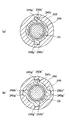
図3(a)は、第3の実施の形態にかかるボールねじ機構の軸線方向断面図であり、図3(b)は、図3(a)のナットをIIIB-IIIB線で切断して矢印方向に見た図であるが、ボールは省略している。図3において、ナット245の外周には、循環路245cを覆うようにして(即ち、少なくとも一部が半径方向外方に位置するようにして)、凸部である隆起部245gが軸線方向に延在するようにして設けられている。一方、スリーブ250の内周には、隆起部245gに対応する凹部である溝250bが形成されている。隆起部245gを溝250bに係合させるようにして、スリーブ250内にナット245が内挿固定され、従って一体的に回転可能となっている。それにより、スリーブ250とナット245との間に高トルクが伝達されたような場合にも、両者の相対滑りを抑制できるようになっており、またナット245の肉厚を減少させることができる。尚、それ以外の構成については、図1の実施の形態と同様であるため説明を省略する。
FIG. 3A is an axial sectional view of the ball screw mechanism according to the third embodiment, and FIG. 3B is an arrow formed by cutting the nut of FIG. 3A along the line IIIB-IIIB. Although it is the figure seen in the direction, the ball is omitted. In FIG. 3, on the outer periphery of the
尚、隆起部は、必ずしも一つに限らない。例えば、図4(a)に示す変形例のように、溝250b’に対向する隆起部245g’を2つ、180度位相で設けたり、図4(b)に示す変形例のように、溝250b”に対向する隆起部245g”を4つ、90度位相で設けたりできるが、数・位相がこれらに限られることはない。
Note that the number of raised portions is not necessarily limited to one. For example, as shown in FIG. 4A, two raised
又、ナットによっては、循環路を2つ設けている場合がある。そこで、例えば、図5(a)に示す変形例のように、溝250b’に対向する隆起部245g’を2つ、180度位相で設けられた循環路245c’を覆うようにして形成したり、図5(b)に示す変形例のように、溝250b”に対向する隆起部245g”を4つ(うち2つについては、180度位相で設けられた循環路245c”を覆うようにして)、90度位相で設けたりできる。
Depending on the nut, there may be two circulation paths. Therefore, for example, as in the modification shown in FIG. 5A, two raised
図6は、第4の実施の形態にかかるボールねじ機構の軸線直交方向断面図であるが、ボールは省略している。図6において、ナット345の外周には、全周に外歯345gが形成されており、一方、スリーブ350の内周には、全周に内歯350bが形成されている。ナット345の外径は、スリーブ350の内径より小さくなっており、従って外歯345gと内歯350bとは直接係合せず、それらの間に円筒状の歯付きベルト353を内挿している。歯付きベルト353は内外周に歯を形成しており、その内側の歯が外歯345gに噛合し、その外側の歯が内歯350bに噛合している。それにより、スリーブ350とナット345とは一体的に回転可能となっている。本実施の形態によれば、歯付きベルト353が弾性体として機能するため、スリーブ350とナット345との間で伝達される衝撃力を緩和できる。尚、歯付きベルト353の代わりに、スリーブ350とナット345との間にゴムや樹脂を溶着して弾性体として機能させても良い。
FIG. 6 is a cross-sectional view in the direction perpendicular to the axis of the ball screw mechanism according to the fourth embodiment, but the balls are omitted. In FIG. 6,
図7は、第5の実施の形態にかかるボールねじ機構の軸線直交方向断面図であるが、ボールは省略している。図7において、ナット445の外周には、循環路445cを覆うようにして(即ち、少なくとも一部が半径方向外方に位置するようにして)、凸部である隆起部445gが軸線方向に延在するようにして設けられている。一方、スリーブ450の内周には、隆起部445gに対応する凹部である溝450bが形成されている。溝450bの幅は、隆起部445gの幅よりも大きくなっており、隆起部445gを溝450bに係合させたとき、生じた周方向両方の空間に緩衝部材453(ゴムや樹脂材からなると好ましい)を配置している。スリーブ450とナット445との間にトルク伝達が生じたときに、凸部である隆起部445gは溝450b内で相対移動するが、この際に衝撃力が生じた場合でも、緩衝部材453がかかる衝撃力を緩和するようになっている。
FIG. 7 is a cross-sectional view in the direction perpendicular to the axis of the ball screw mechanism according to the fifth embodiment, but the balls are omitted. In FIG. 7, the protruding
尚、隆起部は、必ずしも一つに限らない。例えば、図8に示す変形例のように、溝450b’に対向する隆起部445g’を2つ、180度位相で設けたり、図9に示す変形例のように、溝450b”に対向する隆起部445g”を4つ、90度位相で設けたりできるが、数・位相がこれらに限られることはない。
Note that the number of raised portions is not necessarily limited to one. For example, as in the modification shown in FIG. 8, two raised
図10は、第6の実施の形態にかかる電動式パワーステアリング装置511の要部断面図である。本実施の形態においては、図1に示す実施の形態に対して異なる点のみを説明し、共通する構成に関しては同じ符号を付すことで説明を省略する。
FIG. 10 is a cross-sectional view of a main part of an electric
本実施の形態においては、中間軸を省略する代わりに、駆動軸37のギヤ部37aと、スリーブ50の従動ギヤ部50aに係合する歯付きベルト55を設けている。従って、電動モータ35の出力軸35aと共に、駆動ギヤ部37aが回転すれば、歯付きベルト55を介して、従動ギヤ部50aが所定の減速比で回転させられる。それによりスリーブ50とナット45も回転するので、電動モータ35の動力をねじ軸23に伝達することができる。尚、歯付きベルトの替わりにチェーンを用いても良い。又、図2〜9の変形例にかかるボールねじ機構を用いることができることは言うまでもない。
In the present embodiment, instead of omitting the intermediate shaft, a
図11は、第7の実施の形態にかかる電動式パワーステアリング装置611の要部断面図である。図12は、本実施の形態にかかるナットとスリーブの分解斜視図であるが、軸受は省略している。図13(a)は、本実施の形態にかかるナットの端面を示す図であり、図13(b)は、図13(a)の構成をXIIIC-XIIIC線で切断して矢印方向に見た図であり、図13(c)は、デフレクタを示す図である。本実施の形態においては、図1に示す実施の形態に対して異なる点のみを説明し、共通する構成に関しては同じ符号を付すことで説明を省略する。
FIG. 11 is a cross-sectional view of a main part of an electric
本実施の形態においては、ナットとスリーブの構成が異なる。より具体的には、図12に示すように、スリーブ650の底壁650bには、周方向に90度間隔で4つの角柱状の突起650cが軸線方向に突出して(底面から軸線方向に延在して)形成されている。
In the present embodiment, the configurations of the nut and the sleeve are different. More specifically, as shown in FIG. 12, on the
更に、ナット645の本体645aにおけるスリーブ650に対向する端面には、周方向に90度間隔で4つの角柱状の突起645gが軸線方向に突出して形成されている。ナット645とスリーブ650との間には、リング状の第1緩衝体(ゴムまたは樹脂製)635が配置される。第1緩衝体635は、周方向に45度間隔で8つの溝部635aを形成している。溝部635aの形状は、突起645g、650cに対応している。
Further, four
組み付け時には、ナット645の突起645gが、第1緩衝体635の溝部635aを通過し、且つスリーブ650の突起650cが、第1緩衝体635の残りの溝部635aを通過するように配置される。すなわち、周方向に交互に並んだ突起645g、650cとの間に、第1緩衝体635が位置するようになっている。かかる状態で、ねじ部材51の雄ねじ部51aを、スリーブ650の端部内周に形成された雌ねじ部650dに螺合させることで、ナット645とスリーブ650は一体的に回転するように組み付けられる。尚、スリーブ650の外周に軸受27,27(図11参照)を嵌合させ、雌ねじ部650dに、内輪抑え52の雄ねじ部52aを螺合させることで、軸受27,27の組付けを行える。
At the time of assembly, the
本実施の形態によれば、第1緩衝体635が、ナット645の突起645gとスリーブ650の突起650cとの間に配置されているので、トルク伝達時に第1緩衝体635が変形することにより、緩衝効果としてトルク伝達時の振動や騒音を抑制し、またナット645とスリーブ650間の軸線方向ガタを排除することができ、更にはミスアライメント抑制効果も期待できる。
According to the present embodiment, since the
尚、例えばナット645(又はスリーブ650)に、スリーブ650の突起650c(又はナット645の突起645g)に対応するくぼみを設けて、それに係合させても同様の機能を発揮できる。
For example, the same function can be exhibited even if a recess corresponding to the
更に、図12に示すように、ナット645の本体645aは、外周に軸線方向溝645cを形成している。軸線方向溝645cは、図13(b)で一点鎖線で示すスリーブ650にナット645が嵌合することにより、その内周面650eによって外方を覆われ、循環路を形成するようになっている。上述した実施の形態では、循環路はいずれもナット本体を貫通しているが、これを形成するには長いドリルが必要となって加工が比較的困難である。これに対し本実施の形態によれば、フライス加工などにより軸線方向溝645cを容易に加工できる。又、貫通孔形式の循環路では、図13(a)に点線で示すようにナット本体の肉厚が厚くなるが、本実施の形態では実線で示すように本体645aの肉厚を薄くでき、慣性質量を低く抑えて加減速しやすいボールねじ機構を提供できる。
Furthermore, as shown in FIG. 12, the
上述の実施の形態と同様に、本実施の形態においても、図13(c)に示すデフレクタ645bは、ナット645内の転走路を転動してきたボール65を、図13(a)に示すように転送路の接線方向にすくい上げ、かつ図13(b)に示すようにリード角θ方向へすくい上げ軸線方向溝645cに送り出すようになっている。
Similarly to the above-described embodiment, also in this embodiment, the
図14は、第8の実施の形態にかかる電動式パワーステアリング装置711の要部断面図である。本実施の形態においては、図11に示す実施の形態に対して異なる点のみを説明し、共通する構成に関しては同じ符号を付すことで説明を省略する。
FIG. 14 is a cross-sectional view of a main part of an electric
本実施の形態においては、中間軸を省略する代わりに、駆動軸37のギヤ部37aと、スリーブ650の従動ギヤ部650aに係合する歯付きベルト55を設けている。従って、電動モータ35の出力軸35aと共に、駆動ギヤ部37aが回転すれば、歯付きベルト55を介して、従動ギヤ部650aが所定の減速比で回転させられる。それによりスリーブ650とナット645も回転するので、電動モータ35の動力をねじ軸23に伝達することができる。尚、歯付きベルトの替わりにチェーンを用いても良い。
In the present embodiment, instead of omitting the intermediate shaft, a
図15は、第9の実施の形態にかかる電動式パワーステアリング装置811の要部断面図である。図16は、本実施の形態にかかるナットと内輪抑えとを示す分解斜視図である。本実施の形態においては、図11に示す実施の形態に対して異なる点のみを説明し、共通する構成に関しては同じ符号を付すことで説明を省略する。
FIG. 15: is principal part sectional drawing of the electrically driven
本実施の形態においては、図16に示すように、ナット845の内輪抑え852側の端面には、周方向に90度間隔で4つの角柱状の突起845hが軸線方向に突出して形成されている。
In the present embodiment, as shown in FIG. 16, four
尚、上述の実施の形態と同様に、ナット845のスリーブ底壁側の端面には、周方向に90度間隔で4つの角柱状の突起845gが軸線方向に突出して形成されている。
As in the above-described embodiment, four
ナット845と内輪抑え852との間には、リング状の第2緩衝体(ゴムまたは樹脂製)835が配置される。第2緩衝体835は、周方向に90度間隔で4つの溝部835aを形成している。溝部835aの形状は、突起845hに対応している。
A ring-shaped second buffer (made of rubber or resin) 835 is disposed between the
組み付け時には、ナット845の突起845hが、図15に示すように、第2緩衝体835の溝部835aに嵌入するように配置されるが、突起845hは第2緩衝体835を突き抜けることなく、内輪抑え852の端面との間にスキマΔ2を画成する。一方、ナット845の突起845gが、図15に示す第1緩衝体635の溝部に嵌入するように配置されるが、突起845gは第1緩衝体635を突き抜けることなく、スリーブ650の底面との間にスキマΔ1を画成する。かかる状態で、スリーブ650の外周に軸受27,27(図15参照)を嵌合させ、スリーブ650に、内輪抑え852の雄ねじ部852aを螺合させることで、軸受27,27の組付けを行える。
At the time of assembly, the
本実施の形態によれば、ナット845と内輪抑え852との間にスキマΔ2が画成され、且つスリーブ650との間にスキマΔ1が画成されるので、第1緩衝体635又は第2緩衝体835に弾性変形を与えることでナット845は軸線方向に移動可能となり、それにより上述した緩衝効果を高めることができる。又、ナット845の本体845aの両端に設けたデフレクタ845bが、第1緩衝体635及び第2緩衝体835により抑えられているので、動作時にボール65がデフレクタ845bに衝接したときに、その騒音や振動を抑制・吸収することもできる。
According to the present embodiment, the clearance Δ2 is defined between the
図17は、第10の実施の形態にかかる電動式パワーステアリング装置911の要部断面図である。本実施の形態においては、図15に示す実施の形態に対して異なる点のみを説明し、共通する構成に関しては同じ符号を付すことで説明を省略する。
FIG. 17 is a cross-sectional view of a main part of an electric
本実施の形態においては、中間軸を省略する代わりに、駆動軸37のギヤ部37aと、スリーブ650の従動ギヤ部650aに係合する歯付きベルト55を設けている。従って、電動モータ35の出力軸35aと共に、駆動ギヤ部37aが回転すれば、歯付きベルト55を介して、従動ギヤ部650aが所定の減速比で回転させられる。それによりスリーブ650とナット845も回転するので、電動モータ35の動力をねじ軸23に伝達することができる。尚、歯付きベルトの替わりにチェーンを用いても良い。
In the present embodiment, instead of omitting the intermediate shaft, a
尚、以上述べた実施の形態において、第1緩衝体を介在させることなく、ナットとスリーブの突起同士、或いは突起とくぼみ同士を直接係合させることで、トルク伝達を行うようにしても良い。 In the embodiment described above, torque transmission may be performed by directly engaging the protrusions of the nut and the sleeve or the protrusions and the recesses without interposing the first buffer.
図18は、第11の実施の形態にかかる電動式パワーステアリング装置1011の要部断面図である。図19は、図18の構成をIXX-IXX線で切断して矢印方向に見た図であるが、ねじ軸とボールは省略している。本実施の形態においては、図1に示す実施の形態に対して異なる点のみを説明し、共通する構成に関しては同じ符号を付すことで説明を省略する。
FIG. 18 is a cross-sectional view of main parts of an electric
本実施の形態においては、ナットとスリーブとをキーにより連結している。より具体的には、図19において、ナット1045の外周面には軸線方向に延在するキー溝1045jが形成され、それに対向してスリーブ1050の内周面には、軸線方向に延在するキー溝1050fが形成されている。キー溝1045j、1050fにより形成される空間には、角柱状のキー1035が配置されているので、キー1035の剪断力を利用してスリーブ1050からナット1045へのトルク伝達が可能となる。
In the present embodiment, the nut and the sleeve are connected by a key. More specifically, in FIG. 19, a key groove 1045j extending in the axial direction is formed on the outer peripheral surface of the
図20は、第12の実施の形態にかかる電動式パワーステアリング装置1111の要部断面図である。本実施の形態においては、図18に示す実施の形態に対して異なる点のみを説明し、共通する構成に関しては同じ符号を付すことで説明を省略する。
FIG. 20 is a cross-sectional view of a main part of an electric
本実施の形態においては、中間軸を省略する代わりに、駆動軸37のギヤ部37aと、スリーブ1050の従動ギヤ部1050aに係合する歯付きベルト55を設けている。従って、電動モータ35の出力軸35aと共に、駆動ギヤ部37aが回転すれば、歯付きベルト55を介して、従動ギヤ部1050aが所定の減速比で回転させられる。それによりスリーブ1050とナット1045も回転するので、電動モータ35の動力をねじ軸23に伝達することができる。尚、歯付きベルトの替わりにチェーンを用いても良い。
In this embodiment, instead of omitting the intermediate shaft, a
以上、実施の形態を参照して本発明を詳細に説明してきたが、本発明は上記実施の形態に限定して解釈されるべきでなく、その趣旨を損ねない範囲で適宜変更、改良可能であることはもちろんである。本発明は、ステアリングホイールとラック軸とが機械的に連結されていない、いわゆるステアバイワイヤ(SBW)式操舵機構や、4輪操舵(4WS)車に用いる後輪操舵機構などにも適用可能である。 As described above, the present invention has been described in detail with reference to the embodiments. However, the present invention should not be construed as being limited to the above-described embodiments, and can be appropriately changed and improved without departing from the spirit thereof. Of course there is. The present invention is also applicable to a so-called steer-by-wire (SBW) type steering mechanism in which a steering wheel and a rack shaft are not mechanically connected, a rear wheel steering mechanism used in a four-wheel steering (4WS) vehicle, and the like. .
11、511〜1111 電動式パワーステアリング装置
23 ねじ軸
45〜1045 ナット
50〜1050 スリーブ
55 歯付きベルト
65 ボール
11, 511-1111 Electric
Claims (18)
操舵機構に連結されたラック軸と
前記電動モータからの動力を前記ラック軸に伝達する動力伝達機構と、を有し、
前記動力伝達機構は、前記ラック軸に対して連結され又は一体化され且つ雄ねじ溝を備えたねじ軸と、前記ねじ軸の周囲に配置され且つ雌ねじ溝を備えたナットと、前記雄ねじ溝と前記雌ねじ溝との間に形成された転走路内を転動可能な複数の転動体と、前記電動モータから伝達される動力を受ける受け部を有するスリーブと、を有し、
前記ナットは、前記スリーブに対して、前記受け部が前記転走路の半径方向外方に位置するように内挿固定され一体的に回転するようになっていることを特徴とする電動式パワーステアリング装置。 An electric motor;
A rack shaft coupled to a steering mechanism, and a power transmission mechanism for transmitting power from the electric motor to the rack shaft,
The power transmission mechanism is connected to or integrated with the rack shaft and includes a male screw groove, a nut disposed around the screw shaft and provided with a female screw groove, the male screw groove, and the screw shaft. A plurality of rolling elements capable of rolling in a rolling path formed between the female screw groove and a sleeve having a receiving portion for receiving power transmitted from the electric motor;
The electric power steering characterized in that the nut is inserted and fixed with respect to the sleeve so that the receiving portion is located radially outward of the rolling path and is rotated integrally. apparatus.
The electric power steering device according to claim 16, wherein the gear portion is engaged with a toothed belt.
Priority Applications (4)
| Application Number | Priority Date | Filing Date | Title |
|---|---|---|---|
| JP2005007759A JP4696560B2 (en) | 2004-08-06 | 2005-01-14 | Electric power steering device |
| PCT/JP2005/014438 WO2006013976A1 (en) | 2004-08-06 | 2005-08-05 | Electric power steering device |
| DE112005001870T DE112005001870T5 (en) | 2004-08-06 | 2005-08-05 | Electric power steering device |
| US11/659,483 US20090294203A1 (en) | 2004-08-06 | 2005-08-05 | electric power steering apparatus |
Applications Claiming Priority (3)
| Application Number | Priority Date | Filing Date | Title |
|---|---|---|---|
| JP2004230854 | 2004-08-06 | ||
| JP2004230854 | 2004-08-06 | ||
| JP2005007759A JP4696560B2 (en) | 2004-08-06 | 2005-01-14 | Electric power steering device |
Publications (2)
| Publication Number | Publication Date |
|---|---|
| JP2006069517A true JP2006069517A (en) | 2006-03-16 |
| JP4696560B2 JP4696560B2 (en) | 2011-06-08 |
Family
ID=36150557
Family Applications (1)
| Application Number | Title | Priority Date | Filing Date |
|---|---|---|---|
| JP2005007759A Expired - Fee Related JP4696560B2 (en) | 2004-08-06 | 2005-01-14 | Electric power steering device |
Country Status (1)
| Country | Link |
|---|---|
| JP (1) | JP4696560B2 (en) |
Cited By (6)
| Publication number | Priority date | Publication date | Assignee | Title |
|---|---|---|---|---|
| JP2010247675A (en) * | 2009-04-15 | 2010-11-04 | Jtekt Corp | Electric power steering device |
| KR101452556B1 (en) * | 2011-04-18 | 2014-10-21 | 주식회사 만도 | Rack Assist Type Electric Power Steering Apparatus |
| JP2017180543A (en) * | 2016-03-28 | 2017-10-05 | 株式会社ショーワ | Ball screw nut and steering device |
| CN115362099A (en) * | 2020-04-10 | 2022-11-18 | 日立安斯泰莫株式会社 | Steering device |
| DE112020007063T5 (en) | 2020-04-10 | 2023-02-02 | Hitachi Astemo, Ltd. | steering device |
| JP7577497B2 (en) | 2019-12-18 | 2024-11-05 | ニデックインスツルメンツ株式会社 | Drive device and head-up display device |
Citations (6)
| Publication number | Priority date | Publication date | Assignee | Title |
|---|---|---|---|---|
| JPS6312471U (en) * | 1986-06-26 | 1988-01-27 | ||
| JPH10278813A (en) * | 1997-04-10 | 1998-10-20 | Koyo Seiko Co Ltd | Electric power steering device |
| JPH1151145A (en) * | 1997-07-31 | 1999-02-23 | Thk Kk | Side lid type ball screw device |
| JP2000318629A (en) * | 1999-05-12 | 2000-11-21 | Koyo Seiko Co Ltd | Electric power steering device |
| JP2004050884A (en) * | 2002-07-17 | 2004-02-19 | Mitsuba Corp | Power steering device |
| JP2004196036A (en) * | 2002-12-16 | 2004-07-15 | Nsk Ltd | Electric power steering device |
-
2005
- 2005-01-14 JP JP2005007759A patent/JP4696560B2/en not_active Expired - Fee Related
Patent Citations (6)
| Publication number | Priority date | Publication date | Assignee | Title |
|---|---|---|---|---|
| JPS6312471U (en) * | 1986-06-26 | 1988-01-27 | ||
| JPH10278813A (en) * | 1997-04-10 | 1998-10-20 | Koyo Seiko Co Ltd | Electric power steering device |
| JPH1151145A (en) * | 1997-07-31 | 1999-02-23 | Thk Kk | Side lid type ball screw device |
| JP2000318629A (en) * | 1999-05-12 | 2000-11-21 | Koyo Seiko Co Ltd | Electric power steering device |
| JP2004050884A (en) * | 2002-07-17 | 2004-02-19 | Mitsuba Corp | Power steering device |
| JP2004196036A (en) * | 2002-12-16 | 2004-07-15 | Nsk Ltd | Electric power steering device |
Cited By (9)
| Publication number | Priority date | Publication date | Assignee | Title |
|---|---|---|---|---|
| JP2010247675A (en) * | 2009-04-15 | 2010-11-04 | Jtekt Corp | Electric power steering device |
| KR101452556B1 (en) * | 2011-04-18 | 2014-10-21 | 주식회사 만도 | Rack Assist Type Electric Power Steering Apparatus |
| JP2017180543A (en) * | 2016-03-28 | 2017-10-05 | 株式会社ショーワ | Ball screw nut and steering device |
| JP7577497B2 (en) | 2019-12-18 | 2024-11-05 | ニデックインスツルメンツ株式会社 | Drive device and head-up display device |
| CN115362099A (en) * | 2020-04-10 | 2022-11-18 | 日立安斯泰莫株式会社 | Steering device |
| DE112020007063T5 (en) | 2020-04-10 | 2023-02-02 | Hitachi Astemo, Ltd. | steering device |
| DE112020007056T5 (en) | 2020-04-10 | 2023-04-27 | Hitachi Astemo, Ltd. | steering device |
| CN115362099B (en) * | 2020-04-10 | 2023-06-13 | 日立安斯泰莫株式会社 | Steering device |
| US12168483B2 (en) | 2020-04-10 | 2024-12-17 | Hitachi Astemo, Ltd. | Steering apparatus |
Also Published As
| Publication number | Publication date |
|---|---|
| JP4696560B2 (en) | 2011-06-08 |
Similar Documents
| Publication | Publication Date | Title |
|---|---|---|
| EP1524173B1 (en) | Electric power steering apparatus | |
| EP2559607B1 (en) | Electric power steering device | |
| CN107031700B (en) | Steering device | |
| JP5176577B2 (en) | Electric power steering device | |
| US20090260468A1 (en) | Steering device and movement converting device used therefor | |
| WO2006013976A1 (en) | Electric power steering device | |
| US6849025B2 (en) | Frictional roller transmission | |
| JP4807655B2 (en) | Electric power steering device | |
| JP2007196792A (en) | Electric power steering device | |
| US20070006676A1 (en) | Ball screw and electric power steering device including the same | |
| JP4524754B2 (en) | Electric power steering device | |
| JP4696560B2 (en) | Electric power steering device | |
| US7413051B2 (en) | Electric power steering apparatus | |
| JP4678483B2 (en) | Electric power steering device | |
| JP2006027321A (en) | Electric power-steering device | |
| WO2012086678A1 (en) | Electric power steering device | |
| JP4515834B2 (en) | Electric power steering device | |
| JP2010000943A (en) | Output shaft structure of electric power steering device | |
| JP2008296633A (en) | Electric assist mechanism for electric power steering device | |
| JP2005212622A (en) | Electric power steering device | |
| JP4916273B2 (en) | Spline coupling structure and spline device | |
| JP2005186781A (en) | Electric power steering device | |
| KR102111294B1 (en) | Steer-by-wire type power steering apparatus | |
| JP2008002523A (en) | Electric linear actuator | |
| JP2005297823A (en) | Electric power steering device |
Legal Events
| Date | Code | Title | Description |
|---|---|---|---|
| A621 | Written request for application examination |
Free format text: JAPANESE INTERMEDIATE CODE: A621 Effective date: 20080111 |
|
| A131 | Notification of reasons for refusal |
Free format text: JAPANESE INTERMEDIATE CODE: A131 Effective date: 20101028 |
|
| A521 | Request for written amendment filed |
Free format text: JAPANESE INTERMEDIATE CODE: A523 Effective date: 20101125 |
|
| TRDD | Decision of grant or rejection written | ||
| A01 | Written decision to grant a patent or to grant a registration (utility model) |
Free format text: JAPANESE INTERMEDIATE CODE: A01 Effective date: 20110201 |
|
| A61 | First payment of annual fees (during grant procedure) |
Free format text: JAPANESE INTERMEDIATE CODE: A61 Effective date: 20110214 |
|
| R150 | Certificate of patent or registration of utility model |
Ref document number: 4696560 Country of ref document: JP Free format text: JAPANESE INTERMEDIATE CODE: R150 |
|
| LAPS | Cancellation because of no payment of annual fees |