JP2006067115A - Wireless packet communication method and wireless packet communication system - Google Patents
Wireless packet communication method and wireless packet communication system Download PDFInfo
- Publication number
- JP2006067115A JP2006067115A JP2004245651A JP2004245651A JP2006067115A JP 2006067115 A JP2006067115 A JP 2006067115A JP 2004245651 A JP2004245651 A JP 2004245651A JP 2004245651 A JP2004245651 A JP 2004245651A JP 2006067115 A JP2006067115 A JP 2006067115A
- Authority
- JP
- Japan
- Prior art keywords
- packet
- access point
- terminal
- transmission
- wireless
- Prior art date
- Legal status (The legal status is an assumption and is not a legal conclusion. Google has not performed a legal analysis and makes no representation as to the accuracy of the status listed.)
- Withdrawn
Links
Images


Landscapes
- Small-Scale Networks (AREA)
- Mobile Radio Communication Systems (AREA)
Abstract
【課題】 本発明は、アクセスポイントとの間に形成された共通の無線チャネルに対してランダムアクセスする複数の端末がそのアクセスポイント宛に無線パケットを送信することを実現する無線パケット通信方法と、この無線パケット通信方法が適用された無線パケット通信システムとに関し、広範なトラヒックの分布に柔軟に適応し、かつ安価にスループットの向上と、伝送遅延時間の短縮とを実現できることを目的とする。
【解決手段】 1つのアクセスポイントと複数の端末とを含んで構成される無線パケット通信システムにおいて、アクセスポイント宛にパケットの送信を行おうとする端末が、パケットの次に送信の対象となる次パケットのサイズ、または次パケットの有無を示す次パケット情報をパケットに付加することによって構成される。
【選択図】 図1
PROBLEM TO BE SOLVED: To achieve a wireless packet communication method for realizing that a plurality of terminals that randomly access a common wireless channel formed with an access point transmit a wireless packet to the access point; The present invention relates to a radio packet communication system to which this radio packet communication method is applied, and it is intended to flexibly adapt to a wide range of traffic distribution, and to realize an improvement in throughput and a reduction in transmission delay time at a low cost.
In a wireless packet communication system configured to include one access point and a plurality of terminals, a terminal that transmits a packet to an access point receives a next packet to be transmitted next to the packet. Or the next packet information indicating the presence or absence of the next packet is added to the packet.
[Selection] Figure 1
Description
本発明は、アクセスポイントとの間に形成された共通の無線チャネルにランダムアクセスする複数の端末がそのアクセスポイント宛に無線パケットを送信することを実現する無線パケット通信方法と、この無線パケット通信方法が適用された無線パケット通信システムとに関する。 The present invention relates to a wireless packet communication method for realizing that a plurality of terminals randomly accessing a common wireless channel formed with an access point transmit a wireless packet to the access point, and the wireless packet communication method The present invention relates to a wireless packet communication system to which is applied.
従来の無線パケット通信システムでは、複数の端末によって送信された複数のパケットの衝突を削減することによって無線チャネルのスループットの向上と、伝送遅延時間の短縮とを図るために、例えば、下記の第一ないし第三の従来技術に開示されるように、多様なトラヒック制御方式が適用されている。
[第一の従来技術]
後述する第一の非特許文献に記載されるように、端末から基地局に至るアップリンクチャネルのトラヒックが基地局で測定され、そのトラヒックに応じた制御パラメータが端末に報知される輻輳制御方法であって、具体的には、下記の通りに実現されるICMA(Idle-signal Casting Multiple Access)方式が適用された「トラヒック制御方式」
・ 基地局においてアップリンクチャネルのトラヒック等の状態が観測される。
・ 基地局は、観測されたチャネルの状態に基づいて「アイドル信号」または「ビジー信号」をダウンリンクを介して端末に報知する。
・ 端末は、「ビジー信号」を受信した場合には、後続する「アイドル信号」を受信するまで、パケットの送信を抑える。
・ このようなパケットの送信を控える処理は、『基地局が所定のコントロールテーブル(「パケット送信を控える送信待機制限p」と、「パケット発生時に送信パケットを削減するための送信制限q」とが予め登録される。)を構成する複数のレコードの内、上述したように観測されたトラヒックに対して最適なレコードが基地局によって参照されることによって生成され、かつ報知された2つのパラメータp、q』に応じた端末の振る舞いとして実現される。
[第二の従来技術]
後述する第二の非特許文献に記載されるように、端末から基地局に至るアップリンクチャネルのパケット不成功率が基地局によって測定され、そのパケット不成功率に応じた制御パラメータが端末に報知される輻輳制御方法があって、具体的には、下記の通りに実現される「トラヒック制御方法」
・ 輻輳制御は、SLOTTED ALOHA 方式およびICMA/CD方式に基づいて行われる。
・ これらの方式におけるパケット不成功率の傾向に基づいてアップリングチャネルのスループットが最大となるパケット不成功率の閾値が設けられ、基地局は、測定されたパケット不成功率とその閾値との大小関係に基づいて、端末において後続するパケットの送信の制限に適用されるべきパラメータを求め、そのパラメータを端末宛に報知する。
[第三の従来技術]
無線パケット通信におけるアクセス制御法である「CSMA/CA with ACK方式」であって、下記の通りに実現される。
・ 端末は、送信を開始する前の所定の期間(DIFS)にアップリンクチャネルを観測する。
・ このような観測の下で該当するアップリングチャネルが「ビジー」である場合には、端末は、そのアップリンクチャネルが「アイドル」になるまで待機する。
・ 端末は、再び所定の期間(DIFS)にアップリンクチャネルを観測し、その期間にアップリンクチャネルが「アイドル」である場合には、乱数(「バックオフタイム」を示す。)を生成する。
・ さらに、端末は、アップリンクチャネルが「アイドル」である期間に上記のバックオフタイムをスロットタイム毎に減算し、そのバックオフタイムが「0」となったときに後続するパケットを送信する。
・ 一方、このようなパケットの宛先である端末は、該当するパケットを受信した後には、このパケット送信端末にACKを送信する。
・ そのパケットの送信端に該当する端末は、上記のACKを受信することによって、このパケットが宛先端末に届いたことを識別する。
[First prior art]
As described in a first non-patent document to be described later, in a congestion control method in which traffic of an uplink channel from a terminal to a base station is measured by the base station, and a control parameter corresponding to the traffic is notified to the terminal. Specifically, a “traffic control method” to which an ICMA (Idle-signal Casting Multiple Access) method realized as follows is applied.
・ Uplink channel traffic and other conditions are observed at the base station.
The base station broadcasts an “idle signal” or “busy signal” to the terminal via the downlink based on the observed channel state.
When the terminal receives a “busy signal”, the terminal suppresses packet transmission until a subsequent “idle signal” is received.
-The processing to refrain from transmitting packets like this is that the base station has a predetermined control table ("transmission waiting limit p to refrain from packet transmission" and "transmission limit q to reduce transmission packets when packets occur"). Two parameters p generated and broadcasted by the base station referring to the optimum record for the observed traffic among the plurality of records constituting the above. It is realized as the behavior of the terminal according to q ”.
[Second prior art]
As described in the second non-patent document to be described later, the packet failure rate of the uplink channel from the terminal to the base station is measured by the base station, and a control parameter according to the packet failure rate is notified to the terminal. There is a congestion control method, specifically, "traffic control method" realized as follows
• Congestion control is performed based on the SLOTTED ALOHA system and the ICMA / CD system.
-Based on the tendency of packet failure rate in these methods, a threshold of packet failure rate that maximizes the throughput of the uplink channel is set, and the base station determines the size of the measured packet failure rate and the threshold value. Then, a parameter to be applied to the transmission restriction of subsequent packets is obtained at the terminal, and the parameter is notified to the terminal.
[Third prior art]
The “CSMA / CA with ACK method”, which is an access control method in wireless packet communication, is realized as follows.
The terminal observes the uplink channel during a predetermined period (DIFS) before starting transmission.
If the corresponding uplink channel is “busy” under such observation, the terminal waits until the uplink channel becomes “idle”.
The terminal again observes the uplink channel during a predetermined period (DIFS), and generates a random number (indicating “back-off time”) if the uplink channel is “idle” during that period.
Furthermore, the terminal subtracts the back-off time for each slot time during a period when the uplink channel is “idle”, and transmits a subsequent packet when the back-off time becomes “0”.
On the other hand, after receiving the corresponding packet, the terminal that is the destination of such a packet transmits ACK to the packet transmitting terminal.
The terminal corresponding to the transmission end of the packet receives the above ACK and identifies that this packet has reached the destination terminal.
ところで、上述した第一および第二の従来技術では、何れの端末についても、アップリンクチャネルの伝送帯域の割り付けは、各端末の内部に存在する未送信のパケットが考慮されることなく実現され、しかも、適用された方式の特性が把握されなければ適切には実現されなかった。
また、上述した第三の従来例では、輻輳時の制御が行われないために、輻輳時には、アップリンクチャネルのスループットが低下し、あるいは遅延時間が急増する。
By the way, in the first and second conventional techniques described above, for any terminal, the allocation of the uplink channel transmission band is realized without considering the untransmitted packets existing in each terminal, Moreover, it cannot be properly realized unless the characteristics of the applied method are understood.
Further, in the third conventional example described above, since control at the time of congestion is not performed, the throughput of the uplink channel decreases or the delay time increases rapidly at the time of congestion.
本発明は、基本的な構成が大幅に変更されることなく、広範なトラヒックの分布に柔軟に適応し、かつ安価にスループットの向上と、伝送遅延時間の短縮とを実現できる無線パケット通信方法および無線パケット通信システムを提供することを目的とする。 The present invention provides a wireless packet communication method capable of flexibly adapting to a wide range of traffic distributions without greatly changing the basic configuration, and improving throughput and reducing transmission delay time at low cost. An object is to provide a wireless packet communication system.
請求項1に記載の発明では、1つのアクセスポイントと複数の端末とを含んで構成される無線パケット通信システムの無線パケット通信方法において、アクセスポイント宛にパケットの送信を行おうとする端末は、パケットの次に送信の対象となる次パケットのサイズ、または次パケットの有無を示す次パケット情報をパケットに付加する。
すなわち、送信されるパケットにそのパケットの次に送信の対象となる次パケットの情報が付加されることによって、アクセスポイントは、無線パケット通信システムの混雑度を把握することができる。
According to the first aspect of the present invention, in the wireless packet communication method of the wireless packet communication system configured to include one access point and a plurality of terminals, a terminal that transmits a packet to the access point Next packet information indicating the size of the next packet to be transmitted next or the presence or absence of the next packet is added to the packet.
That is, by adding information on the next packet to be transmitted next to the packet to be transmitted, the access point can grasp the degree of congestion of the wireless packet communication system.
請求項2に記載の発明では、請求項1記載の無線パケット通信方法において、アクセスポイントは、パケットに付加された次パケット情報を管理すると共に、パケットの送信端である端末宛に、管理の対象となっている次パケット情報に応じて次パケットを送信するまでの待機期間を示すリリース遅延を含む受信応答信号を送信する。送信端である端末は、受信応答信号を受信後にリリース遅延に等しい時間が経過するまで次パケットの送信を控える。 According to a second aspect of the present invention, in the wireless packet communication method according to the first aspect, the access point manages the next packet information added to the packet, and is managed by the terminal that is the transmission end of the packet. In response to the next packet information, a reception response signal including a release delay indicating a waiting period until the next packet is transmitted is transmitted. The terminal serving as the transmission end refrains from transmitting the next packet until a time equal to the release delay elapses after receiving the reception response signal.
すなわち、リリース遅延が導入されることによって、各端末間におけるパケットの送信権の分散が図られる。
請求項3に記載の発明では、請求項2に記載の無線パケット通信方法において、アクセスポイントは、アクセスポイント宛にパケットの送信を行おうとする端末に該当しない他の端末によって通知された次パケット情報に基づいてリリース遅延を求める。
That is, by introducing a release delay, packet transmission rights are distributed among terminals.
According to a third aspect of the present invention, in the wireless packet communication method according to the second aspect, the access point is the next packet information notified by another terminal not corresponding to the terminal that intends to transmit the packet to the access point. Determine release delay based on
すなわち、リリース遅延は、他の端末の次パケット情報を基に、例えば、他の端末の次パケットの送信が完了するまでの時間が設定される。これにより、アクセスポイントから受信応答信号によりリリース遅延が通知された端末は、その間の送信を控えることにより、他の端末では衝突することなく次パケットを優先的に送信することができる。
請求項4に記載の発明では、請求項1または請求項2に記載の無線パケット通信方法において、アクセスポイントは、アクセスポイント宛にパケットの送信を行おうとする端末に該当しない他の端末によって通知された次パケット情報で示される個々の次パケットの長さの和と、これらの次パケットの送信にかかわるオーバヘッドの平均時間の和の合計として、リリース遅延を求める。
That is, the release delay is set based on the next packet information of the other terminal, for example, the time until the transmission of the next packet of the other terminal is completed. As a result, the terminal notified of the release delay by the reception response signal from the access point can preferentially transmit the next packet without colliding with other terminals by refraining from transmission during that time.
According to a fourth aspect of the present invention, in the wireless packet communication method according to the first or second aspect, the access point is notified by another terminal that does not correspond to the terminal attempting to transmit a packet to the access point. The release delay is obtained as the sum of the sum of the lengths of the individual next packets indicated by the next packet information and the sum of the average time of overhead related to transmission of these next packets.
すなわち、リリース遅延は、上述した次パケットの長さの和と、これらの次パケットの送信にかかわるオーバヘッドの平均時間の和との合計である最適な値に設定される。
請求項5に記載の発明では、1つのアクセスポイントと複数の端末とを備え、複数の端末の内、アクセスポイント宛にパケットの送信を行おうとする端末は、パケットの次に送信の対象となる次パケットのサイズ、または次パケットの有無を示す次パケット情報をパケットに付加すると共に、次パケットに応じてアクセスポイントから送信された受信応答信号を受信後に、その受信応答信号に含まれるリリース遅延に等しい時間が経過するまで次パケットの送信を控える。アクセスポイントは、パケットに付加された次パケット情報を管理すると共に、パケットの送信端である端末宛に受信応答信号を送信通知する。
That is, the release delay is set to an optimum value that is the sum of the sum of the lengths of the next packets described above and the sum of the average times of overheads related to transmission of these next packets.
In the fifth aspect of the present invention, a terminal that includes one access point and a plurality of terminals, and among the plurality of terminals, a terminal that transmits a packet addressed to the access point is a transmission target after the packet. The next packet information indicating the size of the next packet or the presence / absence of the next packet is added to the packet, and after receiving the reception response signal transmitted from the access point according to the next packet, the release delay included in the reception response signal is added. Refrain from transmitting the next packet until the same time has elapsed. The access point manages the next packet information added to the packet, and sends a reception response signal to the terminal that is the transmission end of the packet.
すなわち、送信されるパケットにそのパケットの次に送信の対象となる次パケットの情報が付加されることによって、アクセスポイントは、無線パケット通信システムの混雑度を把握することができる。さらに、リリース遅延が導入されることによって、各端末間におけるパケットの送信権の分散が図られる。
請求項6に記載の発明では、請求項5に記載の無線パケット通信システムにおいて、アクセスポイントは、アクセスポイント宛にパケットの送信を行おうとする端末に該当しない他の端末によって通知された次パケット情報に基づいてリリース遅延を求める。
That is, by adding information on the next packet to be transmitted next to the packet to be transmitted, the access point can grasp the degree of congestion of the wireless packet communication system. Furthermore, by introducing a release delay, packet transmission rights are distributed among terminals.
According to a sixth aspect of the present invention, in the wireless packet communication system according to the fifth aspect, the access point is next packet information notified by another terminal that does not correspond to the terminal that intends to transmit a packet to the access point. Determine release delay based on
すなわち、リリース遅延は、他の端末の次パケット情報を基に、例えば、他の端末の次パケットの送信が完了するまでの時間が設定される。これにより、アクセスポイントから受信応答信号によりリリース遅延が通知された端末は、その間の送信を控えることにより、他の端末では衝突することなく次パケットを優先的に送信することができる。
請求項7に記載の発明では、請求項5に記載の無線パケット通信システムにおいて、アクセスポイントは、アクセスポイント宛にパケットの送信を行おうとする端末に該当しない他の端末によって通知された次パケット情報で示される個々の次パケットの長さの和と、これらの次パケットの送信にかかわるオーバヘッドの平均時間の和の合計として、リリース遅延を求める。
That is, the release delay is set based on the next packet information of the other terminal, for example, the time until the transmission of the next packet of the other terminal is completed. As a result, the terminal notified of the release delay by the reception response signal from the access point can preferentially transmit the next packet without colliding with other terminals by refraining from transmission during that time.
According to a seventh aspect of the invention, in the wireless packet communication system according to the fifth aspect, the access point is next packet information notified by another terminal not corresponding to the terminal that intends to transmit the packet to the access point. The release delay is obtained as the sum of the sum of the lengths of the individual next packets indicated by the above and the sum of the average time of overheads related to transmission of these next packets.
すなわち、リリース遅延は、上述した次パケットの長さの和と、これらの次パケットの送信にかかわるオーバヘッドの平均時間の和との合計である最適な値に設定される。 That is, the release delay is set to an optimum value that is the sum of the sum of the lengths of the next packets described above and the sum of the average times of overheads related to transmission of these next packets.
上述したように本発明によれば、複数の端末がアクセスポイントにパケットを送信する無線パケットネットワークにおいて、輻輳時に、各端末は順次にパケットを送信することができ、かつ衝突の発生が軽減されるので、スループットが向上し、さらに、伝送遅延時間が短縮される。 As described above, according to the present invention, in a wireless packet network in which a plurality of terminals transmit packets to an access point, each terminal can transmit packets sequentially during congestion, and the occurrence of collision is reduced. Therefore, throughput is improved and transmission delay time is further reduced.
以下、図面に基づいて本発明の実施形態について詳細に説明する。
図1は、本発明の第一および第二の実施形態を示す図である。
図において、アクセスポイント(AP)10は無線ゾーン10Zを形成し、その無線ゾーン10Zには、端末20-1〜20-nが位置する。アクセスポイント10は、下記の要素から構成される。
・ アンテナ11
・ そのアンテナ11の給電点に接続された送受信部(TRX)12
・ この送受信部12に縦続接続されたベースバンド処理部(BB)13および制御部(CNT)14
・ その制御部14に縦続接続され、かつ所定の網(図示されない。)に接続されたインタフェース部(I/F)15
上述した制御部14は、下記の要素から構成される。
・ ベースバンド処理部13の上りリンク出力に接続され、かつインタフェース部15の上りリンク入力に接続された次パケット情報抽出部14A
・ 次パケット情報抽出部14Aの制御出力に接続された次パケット情報管理部14B
・ 次パケット情報管理部14Bの入出力端子に接続されたリリース遅延演算部14C
・ リリース遅延演算部14Cの出力に接続された受信応答信号生成部14D
・ 受信応答信号生成部14Dの出力と、ベースバンド処理部13の下りリンク入力とに接続された送信制御部14E
また、端末20-1は、下記の要素から構成される。
・ アンテナ21-1
・ そのアンテナ21-1の給電点に接続された送受信部(TRX)22-1
・ この送受信部22-1に縦続接続されたベースバンド処理部(BB)23-1および制御部(CNT)24-1
・ その制御部24-1に縦続接続され、かつUSB(Universal Serial Bus)、PCMCIA(Personal Computer Memory Card International Association)、赤外線通信ポート、ブルートゥース等のインタフェースを介してパーソナルコンピュータ25-1に接続されたインタフェース部(I/F)26-1
上述した制御部24-1は、下記の要素から構成される。
・ インタフェース部26-1の上りリンク出力と、ベースバンド処理部23-1の上りリンク入力とに接続された送信バッファ24A-1
・ 送信バッファ24A-1の第一の制御端子に接続された次パケット情報管理部24B-1
・ 送信バッファ24A-1の第二の制御端子と、次パケット情報管理部24B-1のモニタ端子と、ベースバンド処理部23-1のモニタ端子とに接続された送信制御部24C-1
・ ベースバンド処理部23-1の上りリンク出力と、送信制御部24C-1の制御入力とに接続されたリリース遅延抽出部24D-1
なお、端末20-2〜20-nの構成については、端末20-1の構成と同じであるので、以下では、対応する要素に添え番号「2」〜「n」がそれぞれ付加された同じ符号を付与し、ここでは、説明および図示を省略する。
Hereinafter, embodiments of the present invention will be described in detail with reference to the drawings.
FIG. 1 is a diagram showing first and second embodiments of the present invention.
In the figure, an access point (AP) 10 forms a radio zone 10Z, and terminals 20-1 to 20-n are located in the radio zone 10Z. The
・ Antenna 11
A transmission / reception unit (TRX) 12 connected to the feeding point of the antenna 11
A baseband processing unit (BB) 13 and a control unit (CNT) 14 cascaded to the transmission / reception unit 12
An interface unit (I / F) 15 connected in cascade to the
The
The next packet
The next packet information management unit 14B connected to the control output of the next packet
Release delay calculation unit 14C connected to the input / output terminal of the next packet information management unit 14B
A reception response signal generation unit 14D connected to the output of the release delay calculation unit 14C
A transmission control unit 14E connected to the output of the reception response signal generation unit 14D and the downlink input of the
The terminal 20-1 includes the following elements.
・ Antenna 21-1
-Transmission / reception unit (TRX) 22-1 connected to the feeding point of the antenna 21-1
A baseband processing unit (BB) 23-1 and a control unit (CNT) 24-1 cascaded to the transmission / reception unit 22-1
-Cascade connected to the control unit 24-1, and connected to the personal computer 25-1 via an interface such as USB (Universal Serial Bus), PCMCIA (Personal Computer Memory Card International Association), infrared communication port, Bluetooth, etc. Interface section (I / F) 26-1
The control unit 24-1 described above includes the following elements.
A transmission buffer 24A-1 connected to the uplink output of the interface unit 26-1 and the uplink input of the baseband processing unit 23-1.
The next packet information management unit 24B-1 connected to the first control terminal of the transmission buffer 24A-1
A
A release delay extraction unit 24D-1 connected to the uplink output of the baseband processing unit 23-1 and the control input of the
Note that the configurations of the terminals 20-2 to 20-n are the same as the configuration of the terminal 20-1, and therefore, the same reference numerals with “2” to “n” added to the corresponding elements will be described below. Here, explanation and illustration are omitted.
図2は、本発明の第一の実施形態の動作を説明する図である。
図3は、本発明の第一の実施形態における端末の動作フローチャートである。
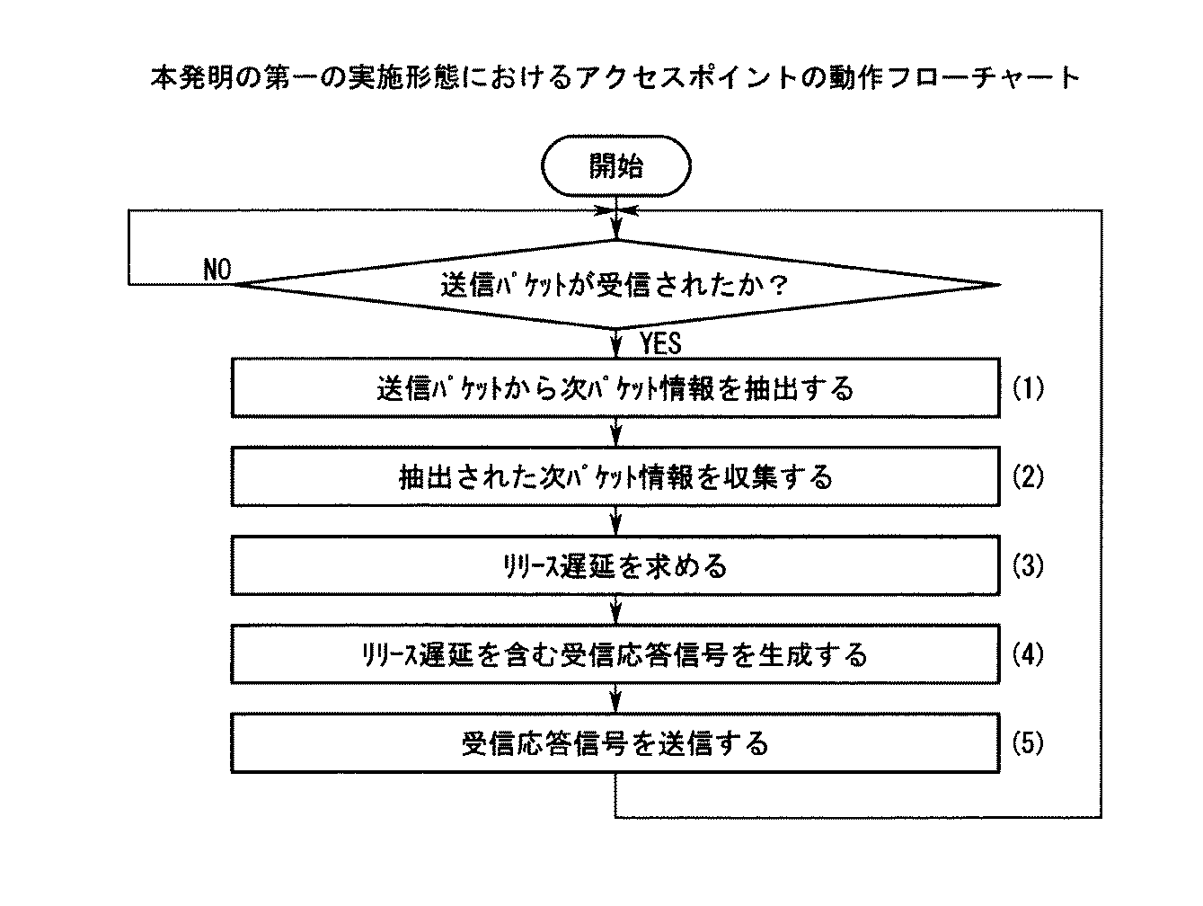
図4は、本発明の第一の実施形態におけるアクセスポイントの動作フローチャートである。
[第一の実施形態]
以下、図1〜図4を参照して本発明の第一の実施形態の動作を説明する。
FIG. 2 is a diagram for explaining the operation of the first embodiment of the present invention.
FIG. 3 is an operation flowchart of the terminal in the first embodiment of the present invention.
FIG. 4 is an operation flowchart of the access point in the first embodiment of the present invention.
[First embodiment]
The operation of the first embodiment of the present invention will be described below with reference to FIGS.
以下では、端末20-1〜20-nに共通の事項については、添え番号「1」〜「n」の何れにも該当し得ることを意味する「c」を該当する端末の要素の符号に付加することによって記述する。
本実施形態では、既述の「CSMA/CA with ACK方式」が適用された無線パケット通信システムに、本願の請求項1、2、5に係る発明が併せて適用される。また、本実施形態の特徴は、アクセスポイント10に備えられた制御部14と、端末20-cに備えられた制御部24-cとの構成および動作にある。
In the following, for items common to the terminals 20-1 to 20-n, “c” meaning that it can correspond to any of the suffix numbers “1” to “n” is used as the element code of the corresponding terminal. Describe by appending.
In the present embodiment, the invention according to
端末20-1では、送信されるべきパケット(以下、「送信パケット」という。)が送信バッファ24A-1に蓄積されていない時刻t0に2つの送信パケットp11、p12が発生し、これらの送信パケットp11、p12は、送信バッファ24A-1に順次格納される(図2(1))。次パケット情報管理部24B-1は、このようにして格納された送信パケットp11、p12の内、最先に送信される送信パケットp11に後続して送信されるべき送信パケットp12を識別し、その送信パケットp12のフォーマットに基づいて下記の項目の何れかに該当する「次パケット情報」を生成する。
・ 送信パケットp12のサイズ
・ 送信パケットp12の有無を示す二値情報
また、端末20-2では、送信バッファ24A-2に送信パケットが蓄積されていない時刻t1(>t0)に2つのパケットp21、p22が発生し、これらのパケットp21、p22は、送信バッファ24A-2に順次格納される(図2(2))。次パケット情報管理部24B-2は、このようにして格納された送信パケットp21、p22の内、最先に送信される送信パケットp21に後続して送信されるべき送信パケットp22を識別し、その送信パケットp22のフォーマットに基づいて下記の項目の何れかに該当する「次パケット情報」を生成する。
・ 送信パケットp22のサイズ
・ 送信パケットp22の有無を示す二値情報
ところで、端末20-1では、パケット発生時(送信バッファにパケットが格納されるとき)に、送信バッファに未送信パケットが存在せず、さらにDIFSの間、チャネルがアイドルであれば、バックオフタイムを利用せずに、送信パケットの生成および送信処理に入る。ここでは、端末20-1は送信バッファに格納されている送信パケットp11の余剰フィールドに、パケットp12の次パケット情報を付加して送信パケットP11を生成する(図3(1)、(2)、(5))。この送信パケットP11は、アクセスポイント10宛に送信される(図3(6)、図2(4))。
In the terminal 20-1, two transmission packets p11 and p12 are generated at time t0 when packets to be transmitted (hereinafter referred to as “transmission packets”) are not accumulated in the transmission buffer 24A-1, and these transmission packets are generated. p11 and p12 are sequentially stored in the transmission buffer 24A-1 (FIG. 2 (1)). The next packet information management unit 24B-1 identifies the transmission packet p12 to be transmitted subsequent to the transmission packet p11 transmitted first among the transmission packets p11 and p12 stored in this way, Based on the format of the transmission packet p12, “next packet information” corresponding to any of the following items is generated.
The size of the transmission packet p12 Binary information indicating the presence / absence of the transmission packet p12 Further, in the terminal 20-2, two packets p21 at time t1 (> t0) when no transmission packet is accumulated in the transmission buffer 24A-2, p22 is generated, and these packets p21 and p22 are sequentially stored in the transmission buffer 24A-2 (FIG. 2 (2)). The next packet information management unit 24B-2 identifies the transmission packet p22 to be transmitted subsequent to the transmission packet p21 transmitted first among the transmission packets p21 and p22 stored in this way, Based on the format of the transmission packet p22, “next packet information” corresponding to any of the following items is generated.
-The size of the transmission packet p22-Binary information indicating the presence / absence of the transmission packet p22 In the terminal 20-1, when a packet occurs (when a packet is stored in the transmission buffer), there is no untransmitted packet in the transmission buffer. In addition, if the channel is idle during DIFS, transmission packet generation and transmission processing is entered without using the back-off time. Here, the terminal 20-1 generates the transmission packet P11 by adding the next packet information of the packet p12 to the surplus field of the transmission packet p11 stored in the transmission buffer (FIG. 3 (1), (2), (Five)). This transmission packet P11 is transmitted to the access point 10 (FIG. 3 (6), FIG. 2 (4)).
また、パケット発生時(送信バッファにパケットが格納されるとき)に、送信バッファに未送信パケットが存在した場合、あるいは送信バッファに未送信パケットが存在しなくてもDIFSの間にチャネルがビジーになった場合には、バックオフタイムを利用した制御を行う。すなわち、チャネルセンスによってDIFSの間、チャネルがアイドルになったときに、バックオフタイムを選択する。そして、バックオフタイムを減算して0になったときに、送信パケットの生成および送信処理に入る。ここでは、端末20-2は送信バッファに格納されている送信パケットp21の余剰フィールドに、パケットp22の次パケット情報を付加して送信パケットP21を生成する(図3(1)、(2)、(3)、(4)、(5))。この送信パケットP21は、アクセスポイント10宛に送信される(図3(6)、図2(4)′)。 Also, when a packet occurs (when a packet is stored in the transmission buffer), if there is an untransmitted packet in the transmission buffer, or if there is no untransmitted packet in the transmission buffer, the channel is busy during DIFS. If this happens, control using the back-off time is performed. That is, the backoff time is selected when the channel becomes idle during DIFS due to channel sensing. Then, when the back-off time is subtracted to become 0, transmission packet generation and transmission processing starts. Here, the terminal 20-2 generates the transmission packet P21 by adding the next packet information of the packet p22 to the surplus field of the transmission packet p21 stored in the transmission buffer (FIG. 3 (1), (2), (3), (4), (5)). This transmission packet P21 is transmitted to the access point 10 (FIG. 3 (6), FIG. 2 (4) ′).
一方、アクセスポイント10では、送受信部12は、アンテナ11を介して上記の送信パケットP11を受信する(図2(5))。制御部14に備えられた次パケット情報抽出部14Aは、ベースバンド処理部13を介してこの送信パケットP11を取り込み、かつ既述のフォーマットに基づいて解析することによって、下記の処理を行う(図2(6))。
・ 送信パケットP11に含まれる「次パケット情報」を抽出する(図4(1))。
・ その「次パケット情報」をこの送信パケットP11から除外することによって既述の送信パケットp11を復元する。
On the other hand, in the
Extract “next packet information” included in the transmission packet P11 (FIG. 4 (1)).
The above-mentioned transmission packet p11 is restored by excluding the “next packet information” from the transmission packet P11.
ベースバンド処理部13は、その送信パケットP11にべーバンド領域で所定の処理を施し、かつ制御部14およびインタフェース部15を介して既述の網にその処理の結果を順次引き渡す。次パケット情報管理部14Bは、次パケット情報抽出部14Aによって抽出された「次パケット情報」を収集し、かつ端末20-1〜20-n毎に管理する(図4(2))。
The
リリース遅延演算部14Cは、このようにして収集された「次パケット情報」に基づいて後述する「リリース遅延演算処理」を行うことによって、「リリース遅延」(ここでは、先行して上記の「次パケット情報」のみが収集されているため、「0」であると仮定する。)を求める(図4(3))。受信応答信号生成部14Dは、その「リリース遅延」を含み、かつ既述の送信パケットP11が受信されたことを意味する「受信応答信号(ACK)」を生成する(図4(4))。 The release delay calculation unit 14C performs a “release delay calculation process” to be described later based on the “next packet information” collected in this manner, thereby performing a “release delay” (here, the above “next delay”). Since only “packet information” is collected, it is assumed that it is “0”) (FIG. 4 (3)). The reception response signal generation unit 14D generates a “reception response signal (ACK)” including the “release delay” and meaning that the transmission packet P11 described above has been received (FIG. 4 (4)).
送信制御部14Eは、ベースバンド処理部13、送受信部12およびアンテナ11を介してダウンリンクチャネル(端末20-1宛)にその「受信応答信号(ACK)」を送出する(図2(7)、図4(5))。
また、端末20-1、20-2は、その「受信応答信号(ACK)」を受信すると、それぞれ既述の送信パケットP21、P12の送信を試みるが、これらの端末20-1、20-2の内、例えば、バックオフタイムが短い一方の端末20-2が他方の端末20-1に先行して送信を行う。
The transmission control unit 14E sends the “reception response signal (ACK)” to the downlink channel (addressed to the terminal 20-1) via the
Further, when the terminals 20-1 and 20-2 receive the “reception response signal (ACK)”, the terminals 20-1 and 20-2 attempt to transmit the transmission packets P21 and P12 described above, respectively. For example, one terminal 20-2 with a short back-off time performs transmission ahead of the other terminal 20-1.
なお、このようにして送信パケットP21が端末20-2によって送信される過程においてその端末20-2の各部によって行われる下記の処理については、送信パケットp11に代えて送信パケットp21が参照される点を除いて既述の通りであるので、ここでは、その説明を省略する。
・ キャリアセンス
・ アップリンクチャネルのアイドル状態の識別
・ 実際に送信される送信パケットの生成
また、この送信パケットP21が受信される過程においてアクセスポイント10およびその各部によって行われる下記の処理についても、その処理の対象が送信パケットP11ではなく送信パケットP21である点を除いて既述の通りであるので、ここでは、その説明を省略する。
・ 「次パケット情報」の抽出
・ その「次パケット情報」を含まない送信パケットの復元
・ リリース遅延演算部14Cによって行われる処理
・ 「リリース遅延」を含む「受信応答信号(ACK)」の生成および送信
ところで、リリース遅延演算部14Cは、下記の手順に基づいて既述の「リリース遅延演算処理」を行う。
・ 次パケット情報抽出部14Aによって抽出され、かつ次パケット情報管理部14Bによって収集された「次パケット情報」の内、受信された送信パケットP21の送信元である端末20-2以外の何れかの端末が送信元に該当する全ての「次パケット情報」で示される「次パケット」のサイズの総和ΣS(または個数の総和ΣN)を求める。
・ その総和ΣS(またはΣN)として、「リリース遅延」を求める。
In addition, in the process in which the transmission packet P21 is transmitted by the terminal 20-2 in this way, the following processing performed by each unit of the terminal 20-2 refers to the transmission packet p21 instead of the transmission packet p11. Except for, the description is omitted here.
・ Carrier sense ・ Identification of uplink channel idle state ・ Generation of transmission packet to be actually transmitted In addition, the following processing performed by the
-Extraction of "next packet information"-Reconstruction of transmission packet not including the "next packet information"-Processing performed by the release delay calculation unit 14C-Generation of "Reception response signal (ACK)" including "release delay" and Transmission By the way, the release delay calculation unit 14C performs the above-described “release delay calculation process” based on the following procedure.
Of the “next packet information” extracted by the next packet
• Calculate the “release delay” as the sum ΣS (or ΣN).
端末20-cでは、制御部24-cは、アンテナ21-c、送受信部22-cおよびベースバンド処理部23-cを介して上述した「受信応答信号(ACK)」を受信する(図2(a))と、下記の処理を行う。
・ 該当する「受信応答信号(ACK)」に含まれる「リリース遅延」を抽出する(図3(a))。
・ 後続して送信すべき次パケットがある場合には、その「リリース遅延」に等しい時間が経過する時点(図2(b)、図3(b))まで、後続する送信パケットの送信(図2(c))を見合わせる。
In the terminal 20-c, the control unit 24-c receives the “reception response signal (ACK)” described above via the antenna 21-c, the transmission / reception unit 22-c, and the baseband processing unit 23-c (FIG. 2). (a)) and the following processing is performed.
Extract the “release delay” included in the corresponding “reception response signal (ACK)” (FIG. 3A).
-If there is a next packet to be transmitted subsequently, transmission of subsequent transmission packets until the time (Fig. 2 (b), Fig. 3 (b)) equal to the "release delay" has elapsed (Fig. 2 (c))
すなわち、端末20-1〜20-nの内、アップリンクチャネルに対する送信パケットの送信を開始した時点で次に送信されるべき「次パケット」が既に与えられている端末は、他の端末が保有する次パケットの送信が完了するリリース遅延の期間待機した後に次パケットの送信を開始する。図2の例では、アクセスポイント10は、端末20-2の送信パケットP21を受信した時点で、端末20-1の送信パケットP11に付加された送信パケットP12の次パケット情報を取得しており、端末20-2の送信パケットP21に対するACKに、送信パケットP12の送信期間に対応するリリース遅延を付加する。端末20-2はそのリリース遅延の期間待機することにより、端末20-1は優先的に送信パケットP21を送信することができる。同様に、端末20-1の送信パケットP21に対するACKには、端末20-2の送信パケットP22の送信期間に対応するリリース遅延が付加されており、端末20-2は優先的に送信パケットP22の送信が可能となる。このように、各端末の次パケット同士が衝突する事態を回避しながら、次パケットの送信権を各端末に均等に付与し、スループットの向上を図ることができる。
That is, of the terminals 20-1 to 20-n, the terminal that has already been given the “next packet” to be transmitted next when transmission of the transmission packet to the uplink channel is started is held by another terminal. After waiting for a release delay period in which the transmission of the next packet to be completed is completed, transmission of the next packet is started. In the example of FIG. 2, when the
また、アップリンクチャネルのスループットが向上し、かつ伝送遅延時間が短縮されるので、伝送品質に併せて、端末20-1〜20-nに提供される通信サービスの品質が高められる。
[第二の実施形態]
以下、図1を参照して本発明の第二の実施形態について説明する。
Moreover, since the throughput of the uplink channel is improved and the transmission delay time is shortened, the quality of the communication service provided to the terminals 20-1 to 20-n can be improved along with the transmission quality.
[Second Embodiment]
Hereinafter, a second embodiment of the present invention will be described with reference to FIG.
本実施形態の特徴は、アクセスポイント10に備えられたリリース遅延演算部14Cによって行われる下記の処理の手順にある。
リリース遅延演算部14Cは、下記の手順に基づいて「リリース遅延」を求める。
(1) 次パケット情報抽出部14Aによって抽出され、かつ次パケット情報管理部14Bによって収集された「次パケット情報」を参照することによって、端末20-1〜20-nのそれぞれについて、下記の値を求める。
・ 「次パケット」のサイズS1〜Sn(または、「次パケット」の有無を示し、かつ該当する「次パケット」がある場合に限って値が「1」となる二値情報N1〜Nn)
・ 端末20-cによって乱数として決定される衝突回避期間Tcwの平均的な値Tcw_av(乱数の値域の中央値である既知の値として与えられる。)と、本実施形態にかかわる無線パケット通信システムに適用された伝送方式や多元接続方式に固有の値であって、個々の送信パケットの送信の開始の遅れを示す固定遅延σ(例えば、第一の実施形態と同様にCSMA/CA方式が適用された場合には、既述の時間DIFSや時間SIFS、ACK送信時間が該当する。)とに対して下式(1) で与えられるオーバヘッドDoh
Doh=Tcw_av+σ ・・・(1)
(2) そのオーバヘッドDohと、上記のサイズS1〜Sn(または二値情報N1〜Nn)とに対して与えられる下式(2) または下式(3) の右辺の値として、端末20-1〜20-n毎の「リリース遅延Rd1〜Rdn」を求める。ただし、iは「1」ないし「n」の全ての整数に該当し、かつjは、「1」ないし「n」の整数の内、i以外の全ての整数である。
A feature of the present embodiment is the following processing procedure performed by the release
The release delay calculation unit 14C obtains “release delay” based on the following procedure.
(1) By referring to the “next packet information” extracted by the next packet
-"Next packet" size S1 to Sn (or binary information N1 to Nn indicating the presence or absence of "next packet" and having a value of "1" only when there is a corresponding "next packet")
The average value Tcw_av of the collision avoidance period Tcw determined as a random number by the terminal 20-c (given as a known value that is the median value of the random number range), and the radio packet communication system according to the present embodiment This is a value specific to the applied transmission method or multiple access method, and indicates a fixed delay σ indicating the start delay of transmission of each transmission packet (for example, the CSMA / CA method is applied as in the first embodiment) In the case of the above-mentioned time DIFS, time SIFS, and ACK transmission time).
Doh = Tcw_av + σ (1)
(2) As the value of the right side of the following equation (2) or the following equation (3) given to the overhead Doh and the above-mentioned sizes S1 to Sn (or binary information N1 to Nn), the terminal 20-1 "Release delay Rd1 to Rdn" every ~ 20-n is obtained. However, i corresponds to all integers “1” to “n”, and j is an integer other than i among the integers “1” to “n”.
すなわち、端末20-cには、既述の「次パケット情報」を含む送信パケットを送信した後には、端末20-1〜20-nの内、その端末20-c以外の全ての端末が保有し、かつその送信パケットに後続して送信されるべき「次パケット」のサイズまたは個数の総和(上式(2)、(3)の右辺の第一項として与えられる。)と、これらの「次パケット」の送信の開始に先行して生じる固定遅延の総和(上式(2)、(3)の右辺の第二項として与えられる。)との和として、「リリース遅延」が設定される。 That is, after the transmission packet including the “next packet information” described above is transmitted to the terminal 20-c, all terminals other than the terminal 20-c among the terminals 20-1 to 20-n are owned. And the sum of the sizes or number of “next packets” to be transmitted subsequent to the transmission packet (given as the first term on the right side of the above formulas (2) and (3)) and these “ “Release delay” is set as the sum of the sum of fixed delays (given as the second term on the right-hand side of equations (2) and (3) above) that precedes the start of transmission of “next packet” .
このように本実施形態によれば、端末20-1〜20-nの何れについても、「リリース遅延」は、これらの端末20-1〜20-nの内、該当する端末以外の全ての端末が保有する「次パケット」の送信にアップリンクチャネルが実際に適用される時間に設定される。
したがって、既述の第一の実施形態に比べて、端末20-1〜20-nのトラヒックの分布や輻輳の程度に対して柔軟かつ適切に、アップリンクの伝送帯域がこれらの端末20-1〜20-nに対して割り付けられる。
As described above, according to the present embodiment, for any of the terminals 20-1 to 20-n, the “release delay” is all terminals other than the corresponding terminals among these terminals 20-1 to 20-n. Is set to the time at which the uplink channel is actually applied to the transmission of the “next packet” held by.
Therefore, as compared with the first embodiment described above, the uplink transmission band can be flexibly and appropriately adapted to the traffic distribution and the degree of congestion of the terminals 20-1 to 20-n. Assigned to ~ 20-n.
なお、本実施形態では、上式(1) の右辺の第一項Tcw_avと第二項σとの双方が定数として予め与えられている。
しかし、本発明はこのような構成に限定されず、例えば、端末20-cからアクセスポイント10にダウンリンクチャネルを介して引き渡される情報と、これらの端末20-cおよびアクセスポイント10の連係によって行われる分散処理とに基づいて、これらの第一項Tcw_avと第二項σとの値が適切な値に設定されてもよい。
In the present embodiment, both the first term Tcw_av and the second term σ on the right side of the above equation (1) are given in advance as constants.
However, the present invention is not limited to such a configuration. For example, the present invention is performed by information delivered from the terminal 20-c to the
また、上述した各実施形態では、「送信パケット」と「次パケット」とのサイズ(語長)が同じであるとは限らない無線パケット通信システムに本発明が適用されている。
しかし、本発明は、このような無線パケット通信システムに限定されず、例えば、アップリンクチャネルを介して伝送される全てのパケットのサイズが同じである無線パケット通信システムにも適用可能である。
In each of the above-described embodiments, the present invention is applied to a wireless packet communication system in which the sizes (word lengths) of “transmission packet” and “next packet” are not necessarily the same.
However, the present invention is not limited to such a wireless packet communication system, and can also be applied to, for example, a wireless packet communication system in which the size of all packets transmitted through the uplink channel are the same.
さらに、このような場合には、既述の式(2)、(3) は、上記の一定のサイズsに対して与えられる下式(4) で代替されてもよい。 Further, in such a case, the above-described equations (2) and (3) may be replaced by the following equation (4) given for the above-mentioned constant size s.
また、上述した各実施形態では、CSMA/CA方式が適用された無線パケット通信システムに本発明が適用されている。
しかし、本発明は、このような無線パケット通信システムに限定されず、例えば、下記の項目の如何にかかわらず多様な無線パケット通信システムに対する適用が可能であり、かつ既存の構成が大幅に変更されることなく安価に伝送品質やサービス品質を高めるために有効である。
・ アップリンクチャネルに適用された多元接続方式、伝送方式(スロット化の有無を含む。)および通信制御の方式
・ アップリンクチャネルを介して伝送されるパケットの構成、形式および内容
・ アップリンクチャネルを介するパケットの伝送を実現する通信手順
さらに、上述した各実施形態では、「次パケット情報」は、送信バッファ24A-cを介して先行して「送信パケット」が送信された時点でその送信バッファ24A-cに格納され、かつ次パケット情報管理部24B-cによって参照された「次パケット」について求められている。
In each of the above-described embodiments, the present invention is applied to a wireless packet communication system to which the CSMA / CA scheme is applied.
However, the present invention is not limited to such a wireless packet communication system. For example, the present invention can be applied to various wireless packet communication systems regardless of the following items, and the existing configuration is significantly changed. It is effective to improve transmission quality and service quality at a low cost.
・ Multiple access method applied to uplink channel, transmission method (including presence / absence of slotting) and communication control method ・ Configuration, format and contents of packet transmitted via uplink channel ・ Uplink channel Further, in each of the above-described embodiments, the “next packet information” is stored in the transmission buffer 24A when the “transmission packet” is transmitted in advance through the transmission buffer 24A-c. The “next packet” stored in -c and referred to by the next packet information management unit 24B-c is obtained.
しかし、このような「次パケット情報」は、送信バッファ24A-cに格納された「次パケット」ではなく、『先行して送信された「送信パケット」の次に送信されることに併せて、内容が上記の時点で確定した「次送信パケット」』について求められてよい。
また、上述した各実施形態では、アクセスポイント10に備えられた制御部14と、端末20-cに備えられた制御部24-cとは、図1に示される専用のハードウエアとして構成されている。
However, such “next packet information” is not “next packet” stored in the transmission buffer 24A-c, but “sent next to“ transmission packet ”transmitted in advance” The content may be obtained for the “next transmission packet” whose contents are determined at the above-mentioned time.
In each embodiment described above, the
しかし、本発明はこのような構成に限定されず、例えば、これらの制御部14と制御部24-cとの双方もしくは一方の全てまたは一部は、汎用のプロセッサ(DSPであってもよい。)によって実行されるソフトウエアとして構成されてもよい。
さらに、本発明は、上述した実施形態に限定されるものではなく、本発明の範囲において多様な実施形態が可能であり、かつ構成装置の全てまたは一部に如何なる改良が施されてもよい。
However, the present invention is not limited to such a configuration. For example, all or part of both or one of the
Furthermore, the present invention is not limited to the above-described embodiments, and various embodiments are possible within the scope of the present invention, and any improvement may be applied to all or part of the constituent devices.
10 アクセスポイント(AP)
10Z 無線ゾーン
11,21 アンテナ
12,22 送受信部(TRX)
13,23 ベースバンド処理部(BB)
14,24 制御部(CNT)
14A 次パケット情報抽出部
14B,24B 次パケット情報管理部
14C リリース遅延演算部
14D 受信応答信号生成部
14E,24C 送信制御部
15,26 インタフェース部(I/F)
20 端末
24A 送信バッファ
24D リリース遅延抽出部
25 パーソナルコンピュータ(PC)
10 Access point (AP)
13, 23 Baseband processing unit (BB)
14, 24 Control unit (CNT)
14A Next packet information extraction unit 14B, 24B Next packet information management unit 14C Release delay calculation unit 14D Reception response
20 Terminal 24A Transmission buffer 24D Release delay extraction unit 25 Personal computer (PC)
Claims (7)
前記アクセスポイント宛にパケットの送信を行おうとする端末は、前記パケットの次に送信の対象となる次パケットのサイズ、または前記次パケットの有無を示す次パケット情報を前記パケットに付加する
ことを特徴とする無線パケット通信方法。 In a wireless packet communication method of a wireless packet communication system configured to include one access point and a plurality of terminals,
A terminal that intends to transmit a packet to the access point adds next packet information indicating the size of the next packet to be transmitted next to the packet or the presence / absence of the next packet to the packet. A wireless packet communication method.
前記アクセスポイントは、
前記パケットに付加された次パケット情報を管理すると共に、前記パケットの送信端である端末宛に前記次パケットを送信するまでの待機期間を示すリリース遅延を含む受信応答信号を送信し、
前記送信端である端末は、
前記受信応答信号を受信後に前記リリース遅延に等しい時間が経過するまで前記次パケットの送信を控える
ことを特徴とする無線パケット通信方法。 The wireless packet communication method according to claim 1, wherein
The access point is
Managing the next packet information added to the packet, and transmitting a reception response signal including a release delay indicating a waiting period until the next packet is transmitted to a terminal which is a transmission end of the packet;
The terminal which is the transmitting end is
The wireless packet communication method characterized by refraining from transmitting the next packet until a time equal to the release delay elapses after receiving the reception response signal.
前記アクセスポイントは、
前記アクセスポイント宛に前記パケットの送信を行おうとする端末に該当しない他の端末によって通知された次パケット情報に基づいて前記リリース遅延を求める
ことを特徴とする無線パケット通信方法。 The wireless packet communication method according to claim 2,
The access point is
The wireless packet communication method, wherein the release delay is obtained based on next packet information notified by another terminal that does not correspond to a terminal that transmits the packet to the access point.
前記アクセスポイントは、
前記アクセスポイント宛に前記パケットの送信を行おうとする端末に該当しない他の端末によって通知された次パケット情報で示される個々の次パケットの長さの和と、これらの次パケットの送信にかかわるオーバヘッドの平均時間の和の合計として、前記リリース遅延を求める
ことを特徴とする無線パケット通信方法。 In the wireless packet communication method according to claim 1 or 2,
The access point is
The sum of the lengths of the individual next packets indicated by the next packet information notified by other terminals not corresponding to the terminal that intends to transmit the packet to the access point, and the overhead associated with the transmission of these next packets The release delay is obtained as the sum of the sum of the average times of the wireless packet communication methods.
前記複数の端末の内、前記アクセスポイント宛にパケットの送信を行おうとする端末は、
前記パケットの次に送信の対象となる次パケットのサイズ、または前記次パケットの有無を示す次パケット情報を前記パケットに付加すると共に、前記次パケットに応じて前記アクセスポイントから送信された受信応答信号を受信後に、その受信応答信号に含まれるリリース遅延に等しい時間が経過するまで前記次パケットの送信を控え、
前記アクセスポイントは、
前記パケットに付加された次パケット情報を管理すると共に、前記パケットの送信端である端末宛に前記受信応答信号を送信する
ことを特徴とする無線パケット通信システム。 One access point and multiple terminals,
Of the plurality of terminals, a terminal that attempts to transmit a packet to the access point is:
Next packet information indicating the size of the next packet to be transmitted next to the packet or the presence / absence of the next packet is added to the packet, and a reception response signal transmitted from the access point according to the next packet Refrain from transmitting the next packet until a time equal to the release delay included in the reception response signal has elapsed,
The access point is
A radio packet communication system characterized by managing next packet information added to the packet and transmitting the reception response signal to a terminal which is a transmission end of the packet.
前記アクセスポイントは、
前記アクセスポイント宛に前記パケットの送信を行おうとする端末に該当しない他の端末によって通知された次パケット情報に基づいて前記リリース遅延を求める
ことを特徴とする無線パケット通信システム。 The wireless packet communication system according to claim 5,
The access point is
The wireless packet communication system, wherein the release delay is obtained based on next packet information notified by another terminal that does not correspond to a terminal that transmits the packet to the access point.
前記アクセスポイントは、
前記アクセスポイント宛に前記パケットの送信を行おうとする端末に該当しない他の端末によって通知された次パケット情報で示される個々の次パケットの長さの和と、これらの次パケットの送信にかかわるオーバヘッドの平均時間の和の合計として、前記リリース遅延を求める
ことを特徴とする無線パケット通信システム。 The wireless packet communication system according to claim 5,
The access point is
The sum of the lengths of the individual next packets indicated by the next packet information notified by other terminals not corresponding to the terminal that intends to transmit the packet to the access point, and the overhead associated with the transmission of these next packets The wireless packet communication system, wherein the release delay is obtained as the sum of the sum of the average times of the two.
Priority Applications (1)
| Application Number | Priority Date | Filing Date | Title |
|---|---|---|---|
| JP2004245651A JP2006067115A (en) | 2004-08-25 | 2004-08-25 | Wireless packet communication method and wireless packet communication system |
Applications Claiming Priority (1)
| Application Number | Priority Date | Filing Date | Title |
|---|---|---|---|
| JP2004245651A JP2006067115A (en) | 2004-08-25 | 2004-08-25 | Wireless packet communication method and wireless packet communication system |
Publications (1)
| Publication Number | Publication Date |
|---|---|
| JP2006067115A true JP2006067115A (en) | 2006-03-09 |
Family
ID=36113217
Family Applications (1)
| Application Number | Title | Priority Date | Filing Date |
|---|---|---|---|
| JP2004245651A Withdrawn JP2006067115A (en) | 2004-08-25 | 2004-08-25 | Wireless packet communication method and wireless packet communication system |
Country Status (1)
| Country | Link |
|---|---|
| JP (1) | JP2006067115A (en) |
Cited By (25)
| Publication number | Priority date | Publication date | Assignee | Title |
|---|---|---|---|---|
| JP2010504687A (en) * | 2006-10-30 | 2010-02-12 | エルジー エレクトロニクス インコーポレイティド | Redirection method for uplink connection |
| US7872986B2 (en) | 2006-10-30 | 2011-01-18 | Lg Electronics Inc. | Method for transitioning between multiple reception levels |
| JP2011510586A (en) * | 2008-01-23 | 2011-03-31 | エレクトロニクス アンド テレコミュニケーションズ リサーチ インスチチュート | Method and apparatus for arbitrary connection in cellular system |
| US7965740B2 (en) | 2007-05-02 | 2011-06-21 | Lg Electronics Inc. | Method of transmitting data in a wireless communication system |
| US8005115B2 (en) | 2007-05-03 | 2011-08-23 | Lg Electronics Inc. | Method of transferring a data block in a wireless communication system |
| US8027363B2 (en) | 2007-04-30 | 2011-09-27 | Lg Electronics Inc. | Method of transmitting data in a wireless communication system |
| US8040806B2 (en) | 2007-04-30 | 2011-10-18 | Lg Electronics Inc. | Methods of generating data block in mobile communication system |
| US8081662B2 (en) | 2007-04-30 | 2011-12-20 | Lg Electronics Inc. | Methods of transmitting data blocks in wireless communication system |
| US8107456B2 (en) | 2007-06-18 | 2012-01-31 | Lg Electronics Inc. | Method of performing uplink synchronization in wireless communication system |
| US8139524B2 (en) | 2007-06-18 | 2012-03-20 | Lg Electronics Inc. | Control channel reception method for receiving broadcast or multicast service |
| US8155648B2 (en) | 2006-08-22 | 2012-04-10 | Lg Electronics, Inc. | Method of transmitting and receiving control information in a wireless communication system |
| US8184570B2 (en) | 2007-04-30 | 2012-05-22 | Lg Electronics Inc. | Method of transmitting data in wireless communication system supporting multimedia broadcast/multicast service |
| US8189493B2 (en) | 2007-04-30 | 2012-05-29 | Lg Electronics Inc. | Method for triggering a measurement report of mobile terminal |
| US8218524B2 (en) | 2007-04-30 | 2012-07-10 | Lg Electronics Inc. | Method for transmitting or receiving data unit using header field existence indicator |
| US8229517B2 (en) | 2007-05-01 | 2012-07-24 | Lg Electronics Inc. | Data transmission/reception method |
| US8400982B2 (en) | 2007-09-20 | 2013-03-19 | Lg Electronics Inc. | Method for handling correctly received but header compression failed packets |
| US8428013B2 (en) | 2006-10-30 | 2013-04-23 | Lg Electronics Inc. | Method of performing random access in a wireless communcation system |
| US8438446B2 (en) | 2007-06-18 | 2013-05-07 | Lg Electronics Inc. | Method for transmitting/receiving broadcast or multicast service and terminal thereof |
| US8463300B2 (en) | 2007-06-18 | 2013-06-11 | Lg Electronics Inc. | Paging information transmission method for effective call setup |
| US8543089B2 (en) | 2007-04-30 | 2013-09-24 | Lg Electronics Inc. | Method for performing an authentication of entities during establishment of wireless call connection |
| US8619685B2 (en) | 2006-10-02 | 2013-12-31 | Lg Electronics Inc. | Method for transmitting and receiving paging message in wireless communication system |
| JP2014112970A (en) * | 2007-03-20 | 2014-06-19 | Nec Corp | Base station, mobile communication system, mobile communication device, and communication method |
| US8811336B2 (en) | 2006-08-22 | 2014-08-19 | Lg Electronics Inc. | Method of performing handover and controlling thereof in a mobile communication system |
| JP2015035744A (en) * | 2013-08-09 | 2015-02-19 | 日本電信電話株式会社 | Radio communication system, radio terminal and radio communication method |
| US8964652B2 (en) | 2007-06-18 | 2015-02-24 | Lg Electronics Inc. | Method for enhancing of controlling radio resources, method for transmitting status report, and receiver in mobile communication system |
-
2004
- 2004-08-25 JP JP2004245651A patent/JP2006067115A/en not_active Withdrawn
Cited By (45)
| Publication number | Priority date | Publication date | Assignee | Title |
|---|---|---|---|---|
| US8155648B2 (en) | 2006-08-22 | 2012-04-10 | Lg Electronics, Inc. | Method of transmitting and receiving control information in a wireless communication system |
| US8768353B2 (en) | 2006-08-22 | 2014-07-01 | Lg Electronics Inc. | Method of transmitting and receiving control information in a wireless communication system |
| US9668240B2 (en) | 2006-08-22 | 2017-05-30 | Lg Electronics Inc. | Method of transmitting and receiving control information in a wireless communication system |
| US8781466B2 (en) | 2006-08-22 | 2014-07-15 | Lg Electronics Inc. | Method of transmitting and receiving control information in a wireless communication system |
| US9325473B2 (en) | 2006-08-22 | 2016-04-26 | Lg Electronics Inc. | Method of transmitting and receiving control information in a wireless communication system |
| US8811336B2 (en) | 2006-08-22 | 2014-08-19 | Lg Electronics Inc. | Method of performing handover and controlling thereof in a mobile communication system |
| US8619685B2 (en) | 2006-10-02 | 2013-12-31 | Lg Electronics Inc. | Method for transmitting and receiving paging message in wireless communication system |
| US9001766B2 (en) | 2006-10-30 | 2015-04-07 | Lg Electronics Inc. | Method for re-direction of uplink access |
| US8054759B2 (en) | 2006-10-30 | 2011-11-08 | Lg Electronics Inc. | Method for transitioning between multiple reception levels |
| US7872986B2 (en) | 2006-10-30 | 2011-01-18 | Lg Electronics Inc. | Method for transitioning between multiple reception levels |
| US9161306B2 (en) | 2006-10-30 | 2015-10-13 | Lg Electronics Inc. | Method for transitioning between multiple reception levels |
| JP2010504687A (en) * | 2006-10-30 | 2010-02-12 | エルジー エレクトロニクス インコーポレイティド | Redirection method for uplink connection |
| US9516695B2 (en) | 2006-10-30 | 2016-12-06 | Lg Electronics Inc. | Method for transitioning between multiple reception levels |
| US8428013B2 (en) | 2006-10-30 | 2013-04-23 | Lg Electronics Inc. | Method of performing random access in a wireless communcation system |
| US8054758B2 (en) | 2006-10-30 | 2011-11-08 | Lg Electronics Inc. | Method for transitioning between multiple reception levels |
| US8576741B2 (en) | 2006-10-30 | 2013-11-05 | Lg Electronics Inc. | Method for transitioning between multiple reception levels |
| US8520644B2 (en) | 2006-10-30 | 2013-08-27 | Lg Electronics Inc. | Method for re-direction of uplink access |
| JP2014112970A (en) * | 2007-03-20 | 2014-06-19 | Nec Corp | Base station, mobile communication system, mobile communication device, and communication method |
| USRE45347E1 (en) | 2007-04-30 | 2015-01-20 | Lg Electronics Inc. | Methods of transmitting data blocks in wireless communication system |
| US8081662B2 (en) | 2007-04-30 | 2011-12-20 | Lg Electronics Inc. | Methods of transmitting data blocks in wireless communication system |
| US8543089B2 (en) | 2007-04-30 | 2013-09-24 | Lg Electronics Inc. | Method for performing an authentication of entities during establishment of wireless call connection |
| US8218524B2 (en) | 2007-04-30 | 2012-07-10 | Lg Electronics Inc. | Method for transmitting or receiving data unit using header field existence indicator |
| US8027363B2 (en) | 2007-04-30 | 2011-09-27 | Lg Electronics Inc. | Method of transmitting data in a wireless communication system |
| US8189493B2 (en) | 2007-04-30 | 2012-05-29 | Lg Electronics Inc. | Method for triggering a measurement report of mobile terminal |
| US8184570B2 (en) | 2007-04-30 | 2012-05-22 | Lg Electronics Inc. | Method of transmitting data in wireless communication system supporting multimedia broadcast/multicast service |
| US8040806B2 (en) | 2007-04-30 | 2011-10-18 | Lg Electronics Inc. | Methods of generating data block in mobile communication system |
| US8229517B2 (en) | 2007-05-01 | 2012-07-24 | Lg Electronics Inc. | Data transmission/reception method |
| US7965740B2 (en) | 2007-05-02 | 2011-06-21 | Lg Electronics Inc. | Method of transmitting data in a wireless communication system |
| US9131003B2 (en) | 2007-05-02 | 2015-09-08 | Lg Electronics Inc. | Method of transmitting data in a wireless communication system |
| US8798070B2 (en) | 2007-05-02 | 2014-08-05 | Lg Electronics Inc. | Method of transmitting data in a wireless communication system |
| US8005115B2 (en) | 2007-05-03 | 2011-08-23 | Lg Electronics Inc. | Method of transferring a data block in a wireless communication system |
| US8649366B2 (en) | 2007-06-18 | 2014-02-11 | Lg Electronics Inc. | Method of performing uplink synchronization in wireless communication system |
| US8438446B2 (en) | 2007-06-18 | 2013-05-07 | Lg Electronics Inc. | Method for transmitting/receiving broadcast or multicast service and terminal thereof |
| US8107456B2 (en) | 2007-06-18 | 2012-01-31 | Lg Electronics Inc. | Method of performing uplink synchronization in wireless communication system |
| US9538490B2 (en) | 2007-06-18 | 2017-01-03 | Lg Electronics Inc. | Method of performing uplink synchronization in wireless communication system |
| US8964652B2 (en) | 2007-06-18 | 2015-02-24 | Lg Electronics Inc. | Method for enhancing of controlling radio resources, method for transmitting status report, and receiver in mobile communication system |
| US8463300B2 (en) | 2007-06-18 | 2013-06-11 | Lg Electronics Inc. | Paging information transmission method for effective call setup |
| US8139524B2 (en) | 2007-06-18 | 2012-03-20 | Lg Electronics Inc. | Control channel reception method for receiving broadcast or multicast service |
| US8400982B2 (en) | 2007-09-20 | 2013-03-19 | Lg Electronics Inc. | Method for handling correctly received but header compression failed packets |
| KR101449757B1 (en) * | 2008-01-23 | 2014-10-13 | 한국전자통신연구원 | Random Access Method and Device in a Cellular System |
| US8797973B2 (en) | 2008-01-23 | 2014-08-05 | Electronics And Telecommunications Research Institute | Apparatus and method for random access in cellular system |
| JP2011510586A (en) * | 2008-01-23 | 2011-03-31 | エレクトロニクス アンド テレコミュニケーションズ リサーチ インスチチュート | Method and apparatus for arbitrary connection in cellular system |
| USRE48969E1 (en) | 2008-01-23 | 2022-03-08 | Electronics And Telecommunications Research Institute | Apparatus and method for random access in cellular system |
| USRE50773E1 (en) | 2008-01-23 | 2026-01-27 | Electronics And Telecommunications Research Institute | Apparatus and method for random access in cellular system |
| JP2015035744A (en) * | 2013-08-09 | 2015-02-19 | 日本電信電話株式会社 | Radio communication system, radio terminal and radio communication method |
Similar Documents
| Publication | Publication Date | Title |
|---|---|---|
| JP2006067115A (en) | Wireless packet communication method and wireless packet communication system | |
| JP4663653B2 (en) | How to access media with multi-channel devices | |
| CN100539525C (en) | Method and apparatus for providing channel access parameters | |
| EP3547632B1 (en) | Method for terminal communication | |
| CN103220788B (en) | Method, node and the access point that node is grouped | |
| CN107079470B (en) | Media access control for licensed assisted access | |
| US10470215B2 (en) | Coexistence of users with different latency requirements | |
| US20160183305A1 (en) | Allocation of uplink resources in orthogonal frequency-division multiple access (ofdma) wireless networks | |
| US10506615B2 (en) | Method for performing communication by using spectrum resource and communications device | |
| US20040257996A1 (en) | Wireless network communication method using access point | |
| US20120163216A1 (en) | Media access control apparatus and method in wireless local area network system | |
| KR101828402B1 (en) | Contention control mechanism | |
| CN111132369A (en) | Method for selecting channel and sender | |
| US9560674B2 (en) | Virtual busy-tone for full-duplex wireless networks | |
| US20080056298A1 (en) | Communication system | |
| CN109803283B (en) | Wireless communication method and communication equipment | |
| KR20150084296A (en) | Wireless local area network system and driving method thereof | |
| US10128999B2 (en) | Efficient protection of basic service set traffic | |
| JP2011035600A (en) | Wireless communication system | |
| WO2016125775A1 (en) | Control device, communication device, control method and program | |
| CN110247738A (en) | Data confirmation method and device | |
| Barcelo et al. | Carrier sense multiple access with enhanced collision avoidance: a performance analysis | |
| KR20230049722A (en) | Device and method for multi-link wireless transmission | |
| Garcia-Luna-Aceves | Carrier resolution multiple access | |
| KR102448310B1 (en) | Method and apparatus for determining contention window size in communication system |
Legal Events
| Date | Code | Title | Description |
|---|---|---|---|
| A300 | Application deemed to be withdrawn because no request for examination was validly filed |
Free format text: JAPANESE INTERMEDIATE CODE: A300 Effective date: 20071106 |