JP2006066501A - Spin cleaning drying apparatus and spin cleaning drying method - Google Patents
Spin cleaning drying apparatus and spin cleaning drying method Download PDFInfo
- Publication number
- JP2006066501A JP2006066501A JP2004245053A JP2004245053A JP2006066501A JP 2006066501 A JP2006066501 A JP 2006066501A JP 2004245053 A JP2004245053 A JP 2004245053A JP 2004245053 A JP2004245053 A JP 2004245053A JP 2006066501 A JP2006066501 A JP 2006066501A
- Authority
- JP
- Japan
- Prior art keywords
- substrate
- drying
- cleaning
- spin
- rotating
- Prior art date
- Legal status (The legal status is an assumption and is not a legal conclusion. Google has not performed a legal analysis and makes no representation as to the accuracy of the status listed.)
- Pending
Links
Images


Classifications
-
- H10P52/00—
-
- H10P72/0406—
-
- B—PERFORMING OPERATIONS; TRANSPORTING
- B08—CLEANING
- B08B—CLEANING IN GENERAL; PREVENTION OF FOULING IN GENERAL
- B08B3/00—Cleaning by methods involving the use or presence of liquid or steam
- B08B3/02—Cleaning by the force of jets or sprays
Landscapes
- Cleaning Or Drying Semiconductors (AREA)
- Drying Of Solid Materials (AREA)
- Mechanical Treatment Of Semiconductor (AREA)
Abstract
【課題】基板を枚葉式でスピン洗浄及びスピン乾燥するにあたり、基板の全面を十分に乾燥させることのできるスピン洗浄乾燥装置及びスピン洗浄乾燥方法を提供すること。
【解決手段】スピンチャック1に保持された基板Wに対向し所定間隔離間した位置に整流板3を設け、整流板3の中央部から乾燥補助気体を噴射するようにした。またスピンチャック1の下方にはフード付スリット孔6Aを有する排気カバー6を設けた。この排気カバー6により洗浄時は発生するミストを上方に舞い上がらすことなく外部に排気し、乾燥時は整流板3によって周辺空気の流れを整流して乱流を発生させず、基板Wの全面を十分に乾燥させることができるようにした。
【選択図】 図1An object of the present invention is to provide a spin cleaning drying apparatus and a spin cleaning drying method capable of sufficiently drying the entire surface of a substrate when performing spin cleaning and spin drying of a substrate in a single wafer mode.
A rectifying plate 3 is provided at a position facing a substrate W held by a spin chuck 1 and spaced apart by a predetermined distance, and a drying auxiliary gas is jetted from a central portion of the rectifying plate 3. An exhaust cover 6 having a hooded slit hole 6A is provided below the spin chuck 1. The exhaust cover 6 exhausts the mist generated during cleaning to the outside without flying upward, and during the drying, the flow of the surrounding air is rectified by the rectifying plate 3 so as not to generate turbulence, and the entire surface of the substrate W is It was made to be able to dry sufficiently.
[Selection] Figure 1
Description
本発明は基板のスピン洗浄乾燥装置及びスピン洗浄乾燥方法に関し、特にCMP(化学機械研磨)装置等に設けられ半導体ウェーハ等の基板を枚葉式でスピン洗浄及び乾燥するスピン洗浄乾燥装置及びスピン洗浄乾燥方法に関する。 The present invention relates to a spin cleaning and drying apparatus and a spin cleaning and drying method for a substrate, and more particularly to a spin cleaning and drying apparatus and a spin cleaning that are provided in a CMP (Chemical Mechanical Polishing) apparatus or the like and spin-clean and dry a substrate such as a semiconductor wafer. It relates to a drying method.
半導体装置や電子部品等は小型化を図るため、素材であるシリコン等のウェーハ(基板)上に多層配線されて形成される。その際、各層の配線を形成する毎に平坦化処理が行われ、その平坦面にまた次の層の配線が形成される。 Semiconductor devices, electronic components, and the like are formed by multilayer wiring on a wafer (substrate) such as silicon, which is a material, in order to reduce the size. At that time, a flattening process is performed every time the wiring of each layer is formed, and the wiring of the next layer is formed again on the flat surface.
このウェーハ(基板)の平坦化にはCMP(化学機械研磨)装置を用いるのが一般的になってきた。この平坦化処理されたウェーハは、CMP装置に設けられたスピン洗浄乾燥装置でスピン回転されながら洗浄液が供給され、最後に純水が供給されて洗浄工程が終了し、更にスピン回転によって純水を外側に排出する乾燥工程が施される。 In order to planarize the wafer (substrate), it has become common to use a CMP (Chemical Mechanical Polishing) apparatus. The planarized wafer is supplied with a cleaning solution while being rotated by a spin cleaning / drying device provided in a CMP apparatus. Finally, pure water is supplied to finish the cleaning process. A drying step of discharging to the outside is performed.
しかし、スピン回転のみによる乾燥ではウェーハの中心部に水滴が残り、また中心部以外でも乾燥が不十分で、これらの部位にウオーターマークが形成される。ウオーターマークが形成されると、ウェーハ上に形成されている微細配線層の質が低下してしまったり、またパーティクルが発生してしまう。 However, when drying is performed only by spin rotation, water droplets remain at the center of the wafer, and drying is not sufficient at portions other than the center, and a water mark is formed at these portions. When the water mark is formed, the quality of the fine wiring layer formed on the wafer deteriorates or particles are generated.
ウェーハ乾燥工程におけるこのような問題を解決するために、スピン洗浄乾燥装置のスピンチャックを囲むカップの上部開口部にウェーハに近接して外部の空気を遮蔽する雰囲気遮断板を設け、雰囲気遮断板の中央部に純水供給口と乾燥補助気体を噴射する気体噴射口とを設けた装置が提案されている。(例えば、特許文献1参照。)。
しかし、前述の特許文献1に記載された装置では、ウェーハに近接して配置された雰囲気遮断板の中央部から純水を供給するため、雰囲気遮断板のウェーハに面した表面に水滴が付着し、その水滴が次の乾燥工程でウェーハ上に落下するため、ウェーハ表面を十分に乾燥させることができなかった。
However, in the apparatus described in the above-mentioned
また、雰囲気遮断板がウェーハに近接して配置されているため、ウェーハの回転によって生じる気体の流れがウェーハの外周部で乱流となり、ウェーハ外周部、特にウェーハ裏面の外周部の乾燥が不十分になるという問題を有していた。 In addition, because the atmosphere blocking plate is located close to the wafer, the gas flow generated by the rotation of the wafer becomes turbulent at the outer periphery of the wafer, and the outer periphery of the wafer, particularly the outer periphery of the back surface of the wafer, is insufficiently dried. Had the problem of becoming.
また、洗浄時及び乾燥時に基板の外側に排出された水分がカップ内面に衝突して発生するミストが上方に舞い上がり、基板に再付着するという問題も有していた。 Further, there has been a problem that mist generated when the water discharged to the outside of the substrate at the time of cleaning and drying collides with the inner surface of the cup soars upward and reattaches to the substrate.
本発明はこのような事情に鑑みてなされたもので、基板を枚葉式でスピン洗浄及びスピン乾燥するにあたり、基板の全面を十分に乾燥させることのできるスピン洗浄乾燥装置及びスピン洗浄乾燥方法を提供することを目的とする。 The present invention has been made in view of such circumstances, and provides a spin cleaning drying apparatus and a spin cleaning drying method capable of sufficiently drying the entire surface of a substrate when performing spin cleaning and spin drying on a single wafer. The purpose is to provide.
前記目的を達成するために、請求項1に記載の発明は、基板を回転させながらリンスノズルから洗浄液を供給して洗浄し、洗浄後の基板を回転させながら乾燥させる枚葉式のスピン洗浄乾燥装置において、前記基板を保持して回転するスピンチャックと、上方に開口部を有するとともに底部に排水口及び排気口が設けられ、前記スピンチャックを包囲するカップと、中央部に気体噴射口を有し、前記スピンチャックに保持された基板に対向し所定間隔離間した位置と上方又は側方に退避した位置とに進退移動可能に設けられた整流板と、が設けられ、前記スピンチャックの下方には、上面に開口された複数のフード付スリット孔を有する排気カバーが設けられていることを特徴とする。
In order to achieve the above object, the invention according to
請求項1の発明によれば、基板の洗浄では整流板は上方又は側方に退避しているので整流板表面に水滴が付着しない。このため、基板の乾燥時に基板面に水滴が落下することがない。更に乾燥時には、基板に対向し所定間隔離間した位置に整流板が配置され、基板の回転による周辺空気の流れが整流されて乱流が発生せず、また中央部から乾燥補助気体を噴射するので、基板の表裏全面が十分に乾燥する。 According to the first aspect of the present invention, when the substrate is washed, the current plate is retracted upward or sideward, so that water droplets do not adhere to the surface of the current plate. For this reason, water droplets do not fall on the substrate surface when the substrate is dried. Further, when drying, a rectifying plate is arranged at a position facing the substrate and spaced apart by a predetermined distance, the flow of ambient air due to the rotation of the substrate is rectified, turbulent flow does not occur, and drying auxiliary gas is injected from the center part. The entire front and back surfaces of the substrate are sufficiently dried.
また、スピンチャックの下方に複数のフード付スリット孔を有する排気カバーが設けられているので、洗浄時及び乾燥時に基板の外側に排出された水分がカップ内面に衝突して発生するミストがフード付スリット孔を経由してカップ外部に排気され、上方に舞い上がることがなく、洗浄時及び乾燥時に悪影響を及ぼすことがない。 In addition, since an exhaust cover having a plurality of hooded slit holes is provided below the spin chuck, the mist generated by the collision of moisture discharged outside the substrate during cleaning and drying with the inner surface of the cup is attached to the hood. It is exhausted to the outside of the cup through the slit hole, does not rise upward, and does not adversely affect washing and drying.
請求項2に記載の発明は、請求項1の発明において、前記整流板は、導電性材料で形成されていることを特徴とする。これによれば、整流板が導電性材料で形成されているので、乾燥気体中で基板が高速回転することによって生じる静電気を整流板を通して外部に放電させることができる。 According to a second aspect of the present invention, in the first aspect of the invention, the rectifying plate is made of a conductive material. According to this, since the current plate is made of a conductive material, static electricity generated by the high-speed rotation of the substrate in the dry gas can be discharged to the outside through the current plate.
また、請求項3に記載の発明は、基板を回転させながらリンスノズルから洗浄液を供給して洗浄し、洗浄後の基板を回転させながら乾燥させる枚葉式のスピン洗浄乾燥装置において、前記基板を保持して回転するスピンチャックと、上方に開口部を有するとともに底部に排水口及び排気口が設けられ、前記スピンチャックを包囲するカップと、先端に気体噴射口を有し、前記基板の中央部から外周部までをトラバースするスキャンアームと、が設けられ、前記スピンチャックの下方には、上面に開口された複数のフード付スリット孔を有する排気カバーが設けられていることを特徴とする。 According to a third aspect of the present invention, there is provided a single wafer type spin cleaning / drying apparatus in which a cleaning liquid is supplied from a rinse nozzle to perform cleaning while rotating the substrate, and the substrate after cleaning is dried while rotating. A spin chuck that holds and rotates, and has an opening at the top and a drain port and an exhaust port at the bottom, a cup that surrounds the spin chuck, a gas injection port at the tip, and a central portion of the substrate And a scan arm that traverses from the outer periphery to the outer periphery, and an exhaust cover having a plurality of hooded slit holes opened on the upper surface is provided below the spin chuck.
請求項3の発明によれば、基板の乾燥時には先端に気体噴射口を有したスキャンアームが乾燥補助気体を噴射しながら基板の中央部から外周部までをトラバースするので、基板の全面が十分に乾燥する。
According to the invention of
また、スピンチャックの下方に複数のフード付スリット孔を有する排気カバーが設けられているので、洗浄時及び乾燥時に基板の外側に排出された水分がカップ内面に衝突して発生するミストがフード付スリット孔を経由してカップ外部に排気され、上方に舞い上がることがなく、洗浄時及び乾燥時に悪影響を及ぼすことがない。 In addition, since an exhaust cover having a plurality of hooded slit holes is provided below the spin chuck, the mist generated by the collision of moisture discharged outside the substrate during cleaning and drying with the inner surface of the cup is attached to the hood. It is exhausted to the outside of the cup through the slit hole, does not rise upward, and does not adversely affect washing and drying.
請求項4に記載の発明は、請求項1、2、又は3のうちいずれか1項に記載の発明において、前記フード付スリット孔は、前記排気カバーの中央部から外周部に向けて形成され、前記フードはスリット孔の長辺の一方側から他方側に向けて形成され、他方側で開口されていることを特徴とする。 According to a fourth aspect of the present invention, in the invention according to any one of the first, second, and third aspects, the hooded slit hole is formed from a central portion of the exhaust cover toward an outer peripheral portion. The hood is formed from one side of the long side of the slit hole toward the other side, and is opened on the other side.
請求項4の発明によれば、排気カバーのフード付スリット孔が排気カバーの中央部から外周部に向けて形成され、フードはスリット孔の長辺の一方側から他方側に向けて形成されて他方側で開口されているので、カップ内に発生するミストを上方に舞い上がらせることなくスリット孔を通してカップ外部に排気することができる。 According to invention of Claim 4, the slit hole with a hood of an exhaust cover is formed toward the outer peripheral part from the center part of an exhaust cover, and the hood is formed toward the other side from the one side of the long side of a slit hole. Since it is opened on the other side, the mist generated in the cup can be exhausted outside the cup through the slit hole without causing the mist to rise upward.
また、請求項5に記載の発明は、基板を回転させながら洗浄及び乾燥する枚葉式のスピン洗浄乾燥方法において、前記基板を第1の回転速度で回転させながら洗浄液を供給し、前記基板を洗浄するリンス工程と、前記基板の回転によって基板の外周近傍に流体の乱流が生じないように、前記流体を整流可能な位置に整流板を配置する工程と、前記基板に乾燥補助気体を供給するとともに、前記第1の回転速度よりも低速の第2の回転速度から前記第1の回転速度よりも高速の第3の回転速度まで段階的に又は連続で回転速度を上げながら前記基板を回転させて、前記基板を乾燥する乾燥工程と、を有することを特徴とする。 According to a fifth aspect of the present invention, in the single wafer type spin cleaning drying method in which cleaning and drying are performed while rotating the substrate, a cleaning liquid is supplied while rotating the substrate at a first rotation speed, and the substrate is A rinsing step for cleaning, a step of arranging a rectifying plate at a position where the fluid can be rectified so that a turbulent flow of fluid does not occur in the vicinity of the outer periphery of the substrate due to rotation of the substrate, and supplying a drying auxiliary gas to the substrate And rotating the substrate while increasing the rotation speed stepwise or continuously from a second rotation speed lower than the first rotation speed to a third rotation speed higher than the first rotation speed. And a drying step of drying the substrate.
請求項5の発明によれば、基板を第1の回転速度で回転させながら洗浄液を供給してリンスし、次に、基板の回転によって周囲の気体の流れに乱流が生じないように整流板を配置し、次に乾燥補助気体を供給するとともに、第1の回転速度よりも低速の第2の回転速度から第1の回転速度よりも高速の第3の回転速度まで回転速度を上げながら基板を乾燥するので、基板の中心部より徐々に乾燥させて基板外周部まで十分に乾燥させることができる。 According to the fifth aspect of the present invention, the cleaning liquid is supplied and rinsed while rotating the substrate at the first rotation speed, and then the rectifying plate prevents the turbulent flow from occurring in the surrounding gas flow due to the rotation of the substrate. And then supplying the drying auxiliary gas and increasing the rotation speed from the second rotation speed lower than the first rotation speed to the third rotation speed higher than the first rotation speed. Thus, the substrate can be dried gradually from the center of the substrate and sufficiently dried to the outer periphery of the substrate.
また、請求項6に記載の発明は、基板を回転させながら洗浄及び乾燥する枚葉式のスピン洗浄乾燥方法において、前記基板を回転させながら洗浄液を供給し、前記基板を洗浄するリンス工程と、前記基板を回転させるとともに前記基板に乾燥補助気体を噴射し、噴射点を基板の中心から外周部までトラバースして、前記基板を乾燥する乾燥工程と、を有することを特徴とする。 The invention according to claim 6 is a single wafer type spin cleaning drying method in which cleaning and drying are performed while rotating the substrate, and a rinsing step of cleaning the substrate by supplying a cleaning liquid while rotating the substrate; A drying step of rotating the substrate and spraying a drying auxiliary gas onto the substrate, traversing the spray point from the center of the substrate to the outer periphery, and drying the substrate.
請求項6の発明によれば、基板を回転させるとともに乾燥補助気体の噴射点を基板の中心から外周部までトラバースするので、基板の中心部から基板外周部まで十分に乾燥させることができる。 According to the invention of claim 6, since the substrate is rotated and the spray point of the drying auxiliary gas is traversed from the center of the substrate to the outer peripheral portion, the substrate can be sufficiently dried from the central portion of the substrate to the outer peripheral portion of the substrate.
また、請求項7に記載の発明は、請求項6の発明において、前記乾燥補助気体の噴射点のトラバースは、基板の中心から外周部に向けてトラバース速度を遅くすることを特徴とする。請求項7の発明によれば、基板表面の面積が増大する外周部にむけてトラバース速度を遅くするので、基板全面を十分に乾燥させることができる。 According to a seventh aspect of the invention, in the sixth aspect of the invention, the traverse of the spray point of the drying auxiliary gas decreases the traverse speed from the center of the substrate toward the outer periphery. According to the seventh aspect of the invention, the traverse speed is reduced toward the outer peripheral portion where the area of the substrate surface increases, so that the entire surface of the substrate can be sufficiently dried.
また、請求項8に記載の発明は、請求項5、6、又は7のうちいずれか1項に記載の発明において、前記乾燥補助気体が、フィルタを通過させた乾燥空気又は窒素ガスであることを特徴とする。請求項8の発明によれば、正常な乾燥空気又は窒素ガスを乾燥補助気体とするので、基板全面を十分に乾燥させることができる。
The invention according to claim 8 is the invention according to any one of
また、請求項9に記載の発明は、請求項5、6、7、又は8のうちいずれか1項に記載の発明において、前記乾燥補助気体にイオンを含有させ、乾燥工程において発生する静電気を空中に放電させることを特徴とする。
The invention according to claim 9 is the invention according to any one of
請求項9の発明によれば、乾燥補助気体にイオンを含有させ、乾燥工程において発生する静電気を空中に放電させるので、基板に形成された半導体装置等が静電破壊されるのを防止することができる。 According to the invention of claim 9, since ions are contained in the drying auxiliary gas and the static electricity generated in the drying process is discharged into the air, the semiconductor device or the like formed on the substrate is prevented from being electrostatically destroyed. Can do.
以上説明したように本発明のスピン洗浄乾燥装置によれば、基板の乾燥時に基板面に水滴が落下することがなく、基板の回転による周辺空気の流れが整流されて乱流が発生せず、また乾燥補助気体を噴射するので基板の全面が十分に乾燥する。また、排気カバーによってカップ内に発生するミストが上方に舞い上がることが防止される。 As described above, according to the spin cleaning drying apparatus of the present invention, water droplets do not fall on the substrate surface when the substrate is dried, the flow of ambient air due to the rotation of the substrate is rectified, and turbulence does not occur. Further, since the drying auxiliary gas is injected, the entire surface of the substrate is sufficiently dried. Further, the exhaust cover prevents mist generated in the cup from rising upward.
また、本発明のスピン洗浄乾燥方法によれば、基板の中心部より徐々に乾燥させて基板外周部まで十分に乾燥させることができる。 Further, according to the spin cleaning drying method of the present invention, the substrate can be dried gradually from the central portion of the substrate and sufficiently dried to the outer peripheral portion of the substrate.
以下添付図面に従って本発明に係るスピン洗浄乾燥装置及びスピン洗浄乾燥方法の好ましい実施の形態について詳説する。尚、各図において同一部材には同一の番号または記号を付している。 The preferred embodiments of the spin cleaning / drying apparatus and spin cleaning / drying method according to the present invention will be described below in detail with reference to the accompanying drawings. In each figure, the same number or symbol is attached to the same member.
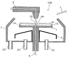
図1は、本発明の実施の形態に係るスピン洗浄乾燥装置を示す断面図である。スピン洗浄乾燥装置10は、上面にウェーハWを保持する3個の支持ピン1A、1A、1Aを有しスピン回転するするスピンチャック1、上方に開口部2Aが形成され、スピンチャック1を囲むカップ2、ウェーハWと所定間隔離れて対向配置された位置と、上方に退避した位置とに移動可能な整流板3、カップ2の開口部2AからウェーハWにリンス液を供給するリンスノズル7、及びカップ2内のスピンチャック1の下方に設けられた排気カバー6等から構成されている。
FIG. 1 is a cross-sectional view showing a spin cleaning / drying apparatus according to an embodiment of the present invention. The spin cleaning / drying
スピンチャック1の中心には気体噴射口1Bが形成され、配管5によって窒素ガス源に接続され、ウェーハWの裏面に乾燥補助気体としての窒素ガスを噴射するようになっている。
A
また、整流板3は、ウェーハWの径よりも大きな径を有する導電性の金属円盤で、所定の距離でウェーハWに対向配置したときに、ウェーハWが回転することによって生じる気体の流れがウェーハWの周縁近傍で乱流とならないように整流する効果を有している。
The rectifying
この整流板3の中心にも下方に向けて気体噴射口3Aが形成され、配管4によって窒素ガス源に接続されてウェーハWの表面に乾燥補助気体としての窒素ガスを噴射するようになっている。
A
整流板3はまた、上方に大きく退避できるようになっており、リンスノズル7からウェーハWにリンス液を供給する時は、この上方の退避位置に位置付けられる。なお、整流板3の退避位置はウェーハWの上方に限らず、ウェーハWの側方に退避するような構成であっても良い。
The rectifying
スピンチャック1を囲むカップ2の底部2Bには排水口2Dが設けられ、リンス液をカップ2外に排出する。またカップ2の底部2Bには中心に対して円周上3等分された位置に排気口2Cが3個設けられている。この排気口2C、2C、2Cは夫々図示しない強制排気装置に接続され、カップ2内の気体やミスト状のリンス液を吸引してカップ2外に排出する。
A
カップ2のスピンチャック1の下部に設けられた排気カバー6は、スピンチャック1の回転軸部を囲むとともに、外周に向けて傾斜した上面を有する筒状カバーで、図2はその排気カバー6の平面図で、図3は排気カバー6の拡大断面図である。
The exhaust cover 6 provided at the lower part of the
図2に示すように、排気カバー6の外周に向けて傾斜した上面には中心部から外周にむけて形成された長方形孔を有するフード付スリット孔6Aが、円周上3等分された位置に3個設けられている。このフード付スリット孔6Aは、図3に示すように、長方形孔の一方側から上方を覆い、他方側に開口したフード6Bを有している。
As shown in FIG. 2, the
また、排気カバー6はこのフード付スリット孔6Aが平面的に見てカップ2の底部2Bに設けられた排気口2C、2C、2Cの中間に位置するように配置され、更にフード付スリット孔6Aのフード6Bの開口部がスピンチャック1の回転方向に対向する向きに開口されている。
Further, the exhaust cover 6 is arranged so that the
排気カバー6のフード付スリット孔6Aはこのように形成されているので、カップ2内部に発生するミストをカップ2内で上方に舞い上がらせることなく、図3の白矢印で示すように排気口2Cに吸引してカップ2外に効率良く排出する。
Since the
次に、このような構成を有するスピン洗浄乾燥装置を用いたスピン洗浄乾燥方法について説明する。図4は、このスピン洗浄乾燥方法の実施の形態を示すタイムチャートである。最初に図5に示すように、整流板3を上方の退避位置に退避させておき、直径200mmのウェーハWをスピンチャック1の3個の支持ピン1A、1A、1Aで3点支持する。
Next, a spin cleaning / drying method using the spin cleaning / drying apparatus having such a configuration will be described. FIG. 4 is a time chart showing an embodiment of this spin cleaning drying method. First, as shown in FIG. 5, the
次いで図4に示すように、スピンチャック1を600rpmの回転速度で回転させながらリンスノズル7からウェーハWに純水を10秒間供給し、ウェーハWの表面を洗浄する(リンス工程)。この時カップ2内にミストが発生するが、ミストは排気カバー6のフード付スリット孔6A、6A、6Aから効率良く吸引され、排気口2C、2C、2Cからカップ2外に排出されるので、ウェーハWに向けて舞い上がることがない。
Next, as shown in FIG. 4, pure water is supplied from the rinse
次に、純水の供給を停止し、図1に示すように、整流板3をウェーハWの上面から5mm程度離間させてウェーハWに対向配置する。次いで、整流板3の中心部に設けられた気体噴射口3A及びスピンチャック1の中心部に設けられた気体噴射口1BからウェーハWに向けて乾燥補助気体としての窒素ガスを噴射する。噴射量は約15L/Minとする。
Next, the supply of pure water is stopped, and the
この状態で図4に示すように、スピンチャック1を400rpmの回転速度で20秒間回転させ、引き続きスピンチャック1の回転速度を600rpmで20秒間、800rpmで20秒間、1,000rpmで5秒間、2,000rpmで5秒間回転させる(乾燥工程)。
In this state, as shown in FIG. 4, the
このように乾燥工程では、最初に低速回転でウェーハWの中心部から徐々に乾燥させ、次いで中速、高速回転させる手順を踏むことにより、表面にウオーターマークを発生させることなくウェーハWの表裏両面を十分に乾燥させることができる。 In this way, in the drying process, both the front and back surfaces of the wafer W are generated without causing a water mark on the surface by first gradually drying from the center of the wafer W at a low speed rotation and then rotating at a medium speed and a high speed. Can be sufficiently dried.
図6は、この乾燥工程の状態を概念的に表わしたものである。ウェーハWの回転によって周囲の気体に乱流が発生するが、本発明の場合は整流板3が気体の流れを整流するのでウェーハWの周辺に発生する乱流が抑制される。また、整流板3が導電性の金属板のため、ウェーハWの高速回転によって乾燥補助気体との摩擦で生じる静電気をカップ2外に放電させるので、ウェーハWに形成された半導体装置等が静電破壊されるのを防止する。
FIG. 6 conceptually shows the state of this drying process. Although the turbulent flow is generated in the surrounding gas by the rotation of the wafer W, in the case of the present invention, the rectifying
なお、スピンチャック1の回転速度を低速から高速に段階的に変化させたが、連続的に変化させてもよい。また、前述した手順のスピンチャック1の回転速度と時間及び窒素ガスの噴射量は、ウェーハWの直径によって適宜変化させる。
Although the rotation speed of the
また、乾燥補助気体として窒素ガスを用いたが、ULPAフィルタ(ultra low penetration air filter)等の高性能エアーフィルタを通した乾燥エアを用いてもよい。更に、乾燥補助気体中にイオナイザでイオンを含有させ、静電気を空中に放電させると一層好適である。 Further, although nitrogen gas is used as the drying auxiliary gas, dry air that has passed through a high-performance air filter such as an ULPA filter (ultra low penetration air filter) may be used. Further, it is more preferable that ions are contained in the drying auxiliary gas by an ionizer to discharge static electricity into the air.
次に、図7に示す本発明の別発明のスピン洗浄乾燥装置について説明する。この別発明のスピン洗浄乾燥装置10Aは、前述したスピン洗浄乾燥装置10に比べて整流板3を有さず、先端に気体噴射口8Aが形成され図示しない駆動手段で駆動されてウェーハWの中央部から外周部外までをトラバースするスキャンアーム8が設けられている。その他の構成は前述したスピン洗浄乾燥装置10と同一であるので説明を省略する。
Next, a spin cleaning / drying apparatus according to another embodiment of the present invention shown in FIG. 7 will be described. The spin cleaning /
スキャンアーム8のスキャン動作は、簡単な構造の旋回方式で、旋回角度に応じて旋回速度を制御するようになっている。なお、このスキャンアーム8のスキャン動作は旋回方式に限らず、既知の直線駆動方式を用いてもよい。 The scanning operation of the scan arm 8 is a simple turning method, and the turning speed is controlled according to the turning angle. The scan operation of the scan arm 8 is not limited to the turning method, and a known linear drive method may be used.
図8は、このスピン洗浄乾燥装置10Aを用いたスピン洗浄乾燥方法の実施の形態を示すタイムチャートである。最初に図9に示すように、スキャンアーム8をカップ2の外部の退避位置に退避させておき、直径200mmのウェーハWをスピンチャック1の3個の支持ピン1A、1A、1Aで3点支持する。
FIG. 8 is a time chart showing an embodiment of a spin cleaning / drying method using the spin cleaning /
次いで図8に示すように、スピンチャック1を600rpmの回転速度で回転させながらリンスノズル7からウェーハWに純水を10秒間供給し、ウェーハWの表面を洗浄する(リンス工程)。この時カップ2内にミストが発生するが、ミストは排気カバー6のフード付スリット孔6A、6A、6Aから効率良く吸引され、排気口2C、2C、2Cからカップ2外に排出されるので、ウェーハWに向けて舞い上がることがない。
Next, as shown in FIG. 8, pure water is supplied from the rinse
次に、純水の供給を停止し、スキャンアーム8先端の噴射口8AをウェーハWの中心部上方に位置付ける。次いで図8に示すように、スピンチャック1を400rpmの回転速度で回転させるとともに、スキャンアーム8先端の噴射口8A及びスピンチャック1の中心部に設けられた気体噴射口1BからウェーハWに向けて乾燥補助気体としての窒素ガスを噴射する。噴射量は約15L/Minとする。図7はこの状態を表わしている。
Next, the supply of pure water is stopped, and the
この状態で図8に示すように、スキャンアーム8からの窒素ガスの噴射点をウェーハWの中心部から外周に向けて60秒かけてスキャンさせる。この時スキャンアーム8の移動速度をウェーハWの中心部では速く移動させ、ウェーハWの外周にゆくほど低速にする。 In this state, as shown in FIG. 8, the nitrogen gas injection point from the scan arm 8 is scanned from the center of the wafer W toward the outer periphery over 60 seconds. At this time, the moving speed of the scan arm 8 is moved faster in the center portion of the wafer W, and is lowered as it goes to the outer periphery of the wafer W.
窒素ガスの噴射点がウェーハWの外周から外れた時点でスキャンアーム8の移動を停止し、窒素ガスの噴射も停止する。次いで、スピンチャック1を2,000rpmで5秒間高速回転させて終了する(乾燥工程)。
When the nitrogen gas injection point deviates from the outer periphery of the wafer W, the movement of the scan arm 8 is stopped, and the nitrogen gas injection is also stopped. Next, the
このように、回転するウェーハWに乾燥補助気体としての窒素ガスを噴射するとともに、窒素ガスの噴射点をウェーハWの中心部から外周に向けてスキャンし、スキャン速度をウェーハWの面積が増大する外周部に行くほど低速にするので、ウェーハWの表面にウオーターマークを発生させることなく、十分にウェーハWを乾燥させることができる。 In this way, while the nitrogen gas as the drying auxiliary gas is sprayed onto the rotating wafer W, the nitrogen gas spray point is scanned from the center of the wafer W toward the outer periphery, and the scan speed increases the area of the wafer W. Since the speed is reduced as it goes to the outer peripheral portion, the wafer W can be sufficiently dried without generating a water mark on the surface of the wafer W.
なお、乾燥工程における静電気対策は前述同様、イオナイザによって乾燥補助気体にイオンを含有させ、発生する静電気を空中に放電させる。また、スピンチャック1の回転速度と時間及び窒素ガスの噴射量も前述同様、ウェーハWの直径によって適宜変化させる。
As for the static electricity countermeasure in the drying process, ions are contained in the drying auxiliary gas by an ionizer as described above, and the generated static electricity is discharged into the air. Further, the rotational speed and time of the
以上説明したように、本発明のスピン洗浄乾燥装置及びスピン洗浄乾燥方法によれば、純水洗浄を施した後のウェーハWの表面にウオーターマークを発生させることなく、十分にウェーハWを乾燥させることができる。 As described above, according to the spin cleaning drying apparatus and the spin cleaning drying method of the present invention, the wafer W is sufficiently dried without generating a water mark on the surface of the wafer W after the pure water cleaning. be able to.
1…スピンチャック;1B、3A、8A…噴射口;2…カップ;2B…底部;2C…排気口;2D…排水口;3…整流板;6…排気カバー;6A…フード付スリット孔;6B…フード;7…リンスノズル;8…スキャンアーム;10、10A…スピン洗浄乾燥装置;W…ウェーハ(基板)
DESCRIPTION OF
Claims (9)
前記基板を保持して回転するスピンチャックと、
上方に開口部を有するとともに底部に排水口及び排気口が設けられ、前記スピンチャックを包囲するカップと、
中央部に気体噴射口を有し、前記スピンチャックに保持された基板に対向し所定間隔離間した位置と上方又は側方に退避した位置とに進退移動可能に設けられた整流板と、が設けられ、
前記スピンチャックの下方には、上面に開口された複数のフード付スリット孔を有する排気カバーが設けられていることを特徴とするスピン洗浄乾燥装置。 In a single wafer type spin cleaning drying apparatus that supplies cleaning liquid from a rinse nozzle while rotating the substrate and cleans it, and dries while rotating the substrate after cleaning,
A spin chuck that holds and rotates the substrate;
A cup having an opening at the top and a drain and an exhaust at the bottom, and surrounding the spin chuck;
A rectifying plate having a gas injection port in the center and facing the substrate held by the spin chuck and spaced apart by a predetermined distance and a rectifying plate provided so as to be able to move forward and backward is provided. And
A spin cleaning and drying apparatus, wherein an exhaust cover having a plurality of slit holes with a hood opened on an upper surface is provided below the spin chuck.
前記基板を保持して回転するスピンチャックと、
上方に開口部を有するとともに底部に排水口及び排気口が設けられ、前記スピンチャックを包囲するカップと、
先端に気体噴射口を有し、前記基板の中央部から外周部までをトラバースするスキャンアームと、が設けられ、
前記スピンチャックの下方には、上面に開口された複数のフード付スリット孔を有する排気カバーが設けられていることを特徴とするスピン洗浄乾燥装置。 In a single wafer type spin cleaning drying apparatus that supplies cleaning liquid from a rinse nozzle while rotating the substrate and cleans it, and dries while rotating the substrate after cleaning,
A spin chuck that holds and rotates the substrate;
A cup having an opening at the top and a drain and an exhaust at the bottom, and surrounding the spin chuck;
A scan arm having a gas injection port at the tip and traversing from the central part to the outer peripheral part of the substrate; and
A spin cleaning and drying apparatus, wherein an exhaust cover having a plurality of slit holes with a hood opened on an upper surface is provided below the spin chuck.
前記フードはスリット孔の長辺の一方側から他方側に向けて形成され、他方側で開口されていることを特徴とする請求項1、2、又は3のうちいずれか1項に記載のスピン洗浄乾燥装置。 The hooded slit hole is formed from the central portion of the exhaust cover toward the outer peripheral portion,
4. The spin according to claim 1, wherein the hood is formed from one side of the long side of the slit hole toward the other side and is opened on the other side. 5. Washing and drying equipment.
前記基板を第1の回転速度で回転させながら洗浄液を供給し、前記基板を洗浄するリンス工程と、
前記基板の回転によって基板の外周近傍に流体の乱流が生じないように、前記流体を整流可能な位置に整流板を配置する工程と、
前記基板に乾燥補助気体を供給するとともに、前記第1の回転速度よりも低速の第2の回転速度から前記第1の回転速度よりも高速の第3の回転速度まで段階的に又は連続で回転速度を上げながら前記基板を回転させて、前記基板を乾燥する乾燥工程と、を有することを特徴とするスピン洗浄乾燥方法。 In the single wafer type spin cleaning drying method in which cleaning and drying are performed while rotating the substrate,
A rinsing step of cleaning the substrate by supplying a cleaning liquid while rotating the substrate at a first rotation speed;
A step of arranging a current plate at a position where the fluid can be rectified so as not to cause a turbulent flow of fluid near the outer periphery of the substrate due to the rotation of the substrate;
While supplying the drying auxiliary gas to the substrate, it is rotated stepwise or continuously from a second rotation speed lower than the first rotation speed to a third rotation speed higher than the first rotation speed. And a drying step of drying the substrate by rotating the substrate while increasing the speed.
前記基板を回転させながら洗浄液を供給し、前記基板を洗浄するリンス工程と、
前記基板を回転させるとともに前記基板に乾燥補助気体を噴射し、噴射点を基板の中心から外周部までトラバースして、前記基板を乾燥する乾燥工程と、を有することを特徴とするスピン洗浄乾燥方法。 In the single wafer type spin cleaning drying method in which cleaning and drying are performed while rotating the substrate,
A rinsing step of cleaning the substrate by supplying a cleaning liquid while rotating the substrate;
A spin cleaning drying method comprising: a drying step of rotating the substrate and spraying a drying auxiliary gas onto the substrate, traversing a spray point from a center of the substrate to an outer peripheral portion, and drying the substrate. .
Priority Applications (4)
| Application Number | Priority Date | Filing Date | Title |
|---|---|---|---|
| JP2004245053A JP2006066501A (en) | 2004-08-25 | 2004-08-25 | Spin cleaning drying apparatus and spin cleaning drying method |
| KR1020050075762A KR20060053113A (en) | 2004-08-25 | 2005-08-18 | Spin cleaning drying device and spin cleaning drying method |
| US11/206,997 US7434588B2 (en) | 2004-08-25 | 2005-08-19 | Spin cleaning and drying apparatus and method of spin cleaning and drying |
| TW094128983A TW200616056A (en) | 2004-08-25 | 2005-08-24 | Spin cleaning and drying apparatus and method of spin cleaning and drying |
Applications Claiming Priority (1)
| Application Number | Priority Date | Filing Date | Title |
|---|---|---|---|
| JP2004245053A JP2006066501A (en) | 2004-08-25 | 2004-08-25 | Spin cleaning drying apparatus and spin cleaning drying method |
Publications (1)
| Publication Number | Publication Date |
|---|---|
| JP2006066501A true JP2006066501A (en) | 2006-03-09 |
Family
ID=35941323
Family Applications (1)
| Application Number | Title | Priority Date | Filing Date |
|---|---|---|---|
| JP2004245053A Pending JP2006066501A (en) | 2004-08-25 | 2004-08-25 | Spin cleaning drying apparatus and spin cleaning drying method |
Country Status (4)
| Country | Link |
|---|---|
| US (1) | US7434588B2 (en) |
| JP (1) | JP2006066501A (en) |
| KR (1) | KR20060053113A (en) |
| TW (1) | TW200616056A (en) |
Cited By (6)
| Publication number | Priority date | Publication date | Assignee | Title |
|---|---|---|---|---|
| JP2012049359A (en) * | 2010-08-27 | 2012-03-08 | Disco Abrasive Syst Ltd | Dicing processing device |
| US10096492B2 (en) | 2012-10-03 | 2018-10-09 | Ebara Corporation | Substrate cleaning apparatus and polishing apparatus |
| WO2020218351A1 (en) * | 2019-04-25 | 2020-10-29 | 株式会社Screenホールディングス | Substrate processing method, semiconductor manufacturing method, and substrate processing device |
| JP2020176786A (en) * | 2019-04-19 | 2020-10-29 | 株式会社Screen Spe テック | Drying device |
| JP2022100702A (en) * | 2020-12-24 | 2022-07-06 | Agc株式会社 | Method for drying mask blank substrate, and method for manufacturing euvl mask blank |
| CN115440633A (en) * | 2022-10-17 | 2022-12-06 | 北京北方华创微电子装备有限公司 | Semiconductor processing equipment and exhaust adjusting mechanism |
Families Citing this family (14)
| Publication number | Priority date | Publication date | Assignee | Title |
|---|---|---|---|---|
| JP4607755B2 (en) * | 2005-12-19 | 2011-01-05 | 東京エレクトロン株式会社 | Substrate cleaning method, substrate cleaning apparatus, control program, and computer-readable storage medium |
| EP1992008A1 (en) * | 2006-02-28 | 2008-11-19 | Sez Ag | Device and method for liquid treating disc-like articles |
| KR100739478B1 (en) * | 2006-08-24 | 2007-07-13 | 세메스 주식회사 | Sheet type substrate processing apparatus and method |
| CN104388935B (en) * | 2014-10-13 | 2017-05-03 | 黄山市恒悦电子有限公司 | Semiconductor silicon flat chip table surface rotating corrosion acid and table surface rotating corrosion technology thereof |
| KR102493017B1 (en) * | 2015-12-18 | 2023-01-31 | 주식회사 케이씨텍 | Rinsing and drying device |
| TWI638394B (en) * | 2016-07-25 | 2018-10-11 | 斯庫林集團股份有限公司 | Substrate processing device |
| TWI770115B (en) * | 2017-02-06 | 2022-07-11 | 新加坡商平面半導體公司 | Removal of process effluents |
| US10985039B2 (en) | 2017-02-06 | 2021-04-20 | Planar Semiconductor, Inc. | Sub-nanometer-level substrate cleaning mechanism |
| WO2018145001A1 (en) | 2017-02-06 | 2018-08-09 | Planar Semiconductor, Inc. | Subnanometer-level light-based substrate cleaning mechanism |
| WO2020100829A1 (en) * | 2018-11-16 | 2020-05-22 | 東京エレクトロン株式会社 | Substrate processing device and method for cleaning substrate processing device |
| CN111775056A (en) * | 2020-07-04 | 2020-10-16 | 刘永 | Splash guard for chemical mechanical polishing |
| CN113197681A (en) * | 2021-05-07 | 2021-08-03 | 太和县人民医院 | Medical instrument operating forceps sterilization cleaning and collecting device |
| CN118455168B (en) * | 2024-07-09 | 2024-12-06 | 山东鸿远新材料科技股份有限公司 | Zirconium dioxide preparation is with wasing drying equipment |
| CN120305700B (en) * | 2025-06-12 | 2025-09-30 | 国蓝新材料技术研发(山东)有限公司 | Aluminum-poly drying equipment for phosphorus oxychloride production |
Family Cites Families (5)
| Publication number | Priority date | Publication date | Assignee | Title |
|---|---|---|---|---|
| JPS5927229B2 (en) * | 1979-09-19 | 1984-07-04 | 富士通株式会社 | spinner |
| JP3116297B2 (en) * | 1994-08-03 | 2000-12-11 | 東京エレクトロン株式会社 | Processing method and processing apparatus |
| JP3745140B2 (en) | 1998-03-16 | 2006-02-15 | 大日本スクリーン製造株式会社 | Substrate processing equipment |
| JP4018958B2 (en) * | 2001-10-30 | 2007-12-05 | 大日本スクリーン製造株式会社 | Substrate processing equipment |
| JP4494840B2 (en) * | 2003-06-27 | 2010-06-30 | 大日本スクリーン製造株式会社 | Foreign matter removing apparatus, substrate processing apparatus, and substrate processing method |
-
2004
- 2004-08-25 JP JP2004245053A patent/JP2006066501A/en active Pending
-
2005
- 2005-08-18 KR KR1020050075762A patent/KR20060053113A/en not_active Withdrawn
- 2005-08-19 US US11/206,997 patent/US7434588B2/en not_active Expired - Fee Related
- 2005-08-24 TW TW094128983A patent/TW200616056A/en unknown
Cited By (9)
| Publication number | Priority date | Publication date | Assignee | Title |
|---|---|---|---|---|
| JP2012049359A (en) * | 2010-08-27 | 2012-03-08 | Disco Abrasive Syst Ltd | Dicing processing device |
| US10096492B2 (en) | 2012-10-03 | 2018-10-09 | Ebara Corporation | Substrate cleaning apparatus and polishing apparatus |
| JP2020176786A (en) * | 2019-04-19 | 2020-10-29 | 株式会社Screen Spe テック | Drying device |
| WO2020218351A1 (en) * | 2019-04-25 | 2020-10-29 | 株式会社Screenホールディングス | Substrate processing method, semiconductor manufacturing method, and substrate processing device |
| JP2020181892A (en) * | 2019-04-25 | 2020-11-05 | 株式会社Screenホールディングス | Substrate processing method, semiconductor manufacturing method, and substrate processing apparatus |
| JP7233294B2 (en) | 2019-04-25 | 2023-03-06 | 株式会社Screenホールディングス | SUBSTRATE PROCESSING METHOD, SEMICONDUCTOR MANUFACTURING METHOD AND SUBSTRATE PROCESSING APPARATUS |
| JP2022100702A (en) * | 2020-12-24 | 2022-07-06 | Agc株式会社 | Method for drying mask blank substrate, and method for manufacturing euvl mask blank |
| CN115440633A (en) * | 2022-10-17 | 2022-12-06 | 北京北方华创微电子装备有限公司 | Semiconductor processing equipment and exhaust adjusting mechanism |
| CN115440633B (en) * | 2022-10-17 | 2023-07-11 | 北京北方华创微电子装备有限公司 | Semiconductor process equipment and exhaust gas adjusting mechanism |
Also Published As
| Publication number | Publication date |
|---|---|
| US7434588B2 (en) | 2008-10-14 |
| US20060042666A1 (en) | 2006-03-02 |
| TW200616056A (en) | 2006-05-16 |
| KR20060053113A (en) | 2006-05-19 |
Similar Documents
| Publication | Publication Date | Title |
|---|---|---|
| JP2006066501A (en) | Spin cleaning drying apparatus and spin cleaning drying method | |
| KR102450849B1 (en) | Wafer cleaning apparatus and wafer processing apparatus | |
| US9956594B2 (en) | Substrate processing method | |
| JP3976718B2 (en) | Wafer dryer | |
| US8122899B2 (en) | Apparatus and method for treating substrate | |
| JP4976949B2 (en) | Substrate processing equipment | |
| TWI529798B (en) | Substrate processing device, substrate processing method, and memory medium | |
| JP7224403B2 (en) | SUBSTRATE CLEANING APPARATUS AND SUBSTRATE CLEANING METHOD | |
| TWI620238B (en) | Substrate processing method and substrate processing device | |
| US6494220B1 (en) | Apparatus for cleaning a substrate such as a semiconductor wafer | |
| JP6718714B2 (en) | Substrate processing method and substrate processing apparatus | |
| KR20140086840A (en) | Substrate cleaning apparatus | |
| JP2020115513A (en) | Substrate processing method and substrate processing apparatus | |
| KR102338647B1 (en) | Substrate cleaning apparatus | |
| CN113471108B (en) | Vertical rotatory processing apparatus of wafer based on marangoni effect | |
| JP2017188665A (en) | Substrate processing apparatus and substrate processing method | |
| JP7290695B2 (en) | Cleaning equipment for ultrasonic cleaning equipment and cleaning tools | |
| JP6775638B2 (en) | Substrate cleaning equipment | |
| CN100452307C (en) | Method and apparatus for cleaning and drying wafer | |
| US9764364B2 (en) | Apparatus and methods for movable megasonic wafer probe | |
| JP5017258B2 (en) | Apparatus and method for liquid treatment of wafer-like articles | |
| JP4342324B2 (en) | Substrate processing method and substrate processing apparatus | |
| JP7336967B2 (en) | SUBSTRATE PROCESSING APPARATUS AND SUBSTRATE PROCESSING METHOD | |
| WO2019150683A1 (en) | Substrate cleaning device, substrate processing device, ultrasonic cleaning fluid supply device, and recording medium | |
| JP6934918B2 (en) | Substrate cleaning equipment |
Legal Events
| Date | Code | Title | Description |
|---|---|---|---|
| A621 | Written request for application examination |
Free format text: JAPANESE INTERMEDIATE CODE: A621 Effective date: 20060630 |
|
| A977 | Report on retrieval |
Free format text: JAPANESE INTERMEDIATE CODE: A971007 Effective date: 20081203 |
|
| A131 | Notification of reasons for refusal |
Free format text: JAPANESE INTERMEDIATE CODE: A131 Effective date: 20081217 |
|
| A02 | Decision of refusal |
Free format text: JAPANESE INTERMEDIATE CODE: A02 Effective date: 20090409 |