JP2006060516A - Foldable mobile phone - Google Patents
Foldable mobile phone Download PDFInfo
- Publication number
- JP2006060516A JP2006060516A JP2004240282A JP2004240282A JP2006060516A JP 2006060516 A JP2006060516 A JP 2006060516A JP 2004240282 A JP2004240282 A JP 2004240282A JP 2004240282 A JP2004240282 A JP 2004240282A JP 2006060516 A JP2006060516 A JP 2006060516A
- Authority
- JP
- Japan
- Prior art keywords
- housing
- casing
- front surface
- mobile phone
- concave portion
- Prior art date
- Legal status (The legal status is an assumption and is not a legal conclusion. Google has not performed a legal analysis and makes no representation as to the accuracy of the status listed.)
- Pending
Links
Images


Landscapes
- Telephone Set Structure (AREA)
Abstract
【課題】 片手だけで容易に折り畳んだ状態から開いた状態にすることが可能な折り畳み式携帯電話機を提供する。
【解決手段】 折り畳み式携帯電話機(1)は、第1の筐体(11)、第2の筐体(12)、およびこれらを回動可能に連結するヒンジ部(13)から成り、開いた状態で第1の筐体(11)を把持されて使用される。第1の筐体(11)の前面のうち親指の近くに位置する部位に側面に達する凹部(21)を設け、第2の筐体(12)の前面のうち折り畳んだ状態で凹部(21)に対向する部位に側面に達する凹部(31)を設ける。折り畳んだ状態では、側面に開口を有する穴が凹部(21,31)によって形成され、その穴に親指の先端を挿入して開いた状態とするようにする。また、開口(21)内に上下方向の軸を中心に回動する回動体を設けて、開口から穴の内部全体が見えないようにする。
【選択図】 図1PROBLEM TO BE SOLVED: To provide a foldable mobile phone that can be easily folded from a folded state with only one hand.
A foldable mobile phone (1) is composed of a first casing (11), a second casing (12), and a hinge portion (13) that rotatably couples the first casing (11), and is opened. In use, the first casing (11) is held and used. A concave portion (21) that reaches the side surface is provided at a portion of the front surface of the first housing (11) located near the thumb, and the concave portion (21) is folded in the front surface of the second housing (12). A recess (31) that reaches the side surface is provided at a portion facing the surface. In the folded state, a hole having an opening on the side surface is formed by the recess (21, 31), and the tip of the thumb is inserted into the hole so that the hole is opened. In addition, a rotating body that rotates about the vertical axis is provided in the opening (21) so that the entire inside of the hole cannot be seen from the opening.
[Selection] Figure 1
Description
本発明は、折り畳み式の携帯電話機に関する。 The present invention relates to a foldable mobile phone.
近年、非使用時に小型になる折り畳み式携帯電話機の普及が目覚ましい。従来の折り畳み式携帯電話機5の外観を図14、図15に示し、使用者の手に把持された使用時の様子を図16に示す。図14、図15はそれぞれ携帯電話機5の折り畳んだ状態および開いた状態を表している。
In recent years, the spread of a foldable mobile phone that is small when not in use is remarkable. FIG. 14 and FIG. 15 show the external appearance of a conventional foldable
携帯電話機5は、左右方向の大きさが略等しい第1の筐体51と第2の筐体52と、ヒンジ部53より成る。ヒンジ部53は、第1の筐体51の上端部と第2の筐体52の下端部を連結しており、第1の筐体51と第2の筐体52は、ヒンジ部53に含まれる左右方向に延びる軸を中心に、相対的に回動可能である。
The
携帯電話機5は、第1の筐体51の前面(使用時に使用者の顔に対向する面)と第2の筐体52の前面が対向する折り畳んだ状態(図14)と、第1の筐体51の前面と第2の筐体52の前面が対向しない開いた状態(図15)とをとる。使用者は、携帯電話機5を使用する際、図14の折り畳んだ状態から図15の開いた状態とする。そして、図16に示すように、第1の筐体51を背面側から把持して、使用する。
The
第1の筐体51の前面には、電話番号等の入力のために操作される複数のキー54が設けられており、第2の筐体52の前面には、液晶表示器から成る表示部55が設けられている。図示しないが、第1の筐体51の下端付近には音声を取り込むマイクロフォンが内蔵されており、第2の筐体52の上端付近には音声を出力するスピーカが内蔵されている。また、第1の筐体51と第2の筐体52のいずれかに、電波を送受信するアンテナが設けられている。
A plurality of
非使用時に携帯電話機5が誤って開いた状態となるのを防止するために、ヒンジ部53には、折り畳んだ状態にある第1の筐体51と第2の筐体52を互いに近づける方向に付勢する機構が設けられている。このような付勢機構は、例えば、特開平7−131850号や特開2003−87873号に開示されているように、回動軸を囲む形態のコイルばねを用いて実現することができる。
折り畳んだ状態にある第1の筐体51と第2の筐体52を互いに近づける方向に付勢する機構が設けられている折り畳み式携帯電話機5では、折り畳んだ状態から開いた状態とするために、使用者は次のような操作をする。すなわち、第1の筐体51を一方の手の親指と他の指で左右から挟み、第2の筐体52を他方の手の親指と他の指で左右から挟んで、筐体51、52を回動させる。あるいは、第1の筐体51を一方の手の親指と他の指で左右から挟み、第2の筐体52の上端面を他方の手の親指で押して、筐体52を回動させる。いずれにしても、携帯電話機を開いた状態とするためには、使用者は両手を使う必要がある。
In the foldable
しかしながら、使用者が常に両手を自由に使えるとは限らず、外出先で使用することを前提とする携帯電話機では、むしろ、使用者が荷物を持っているときに着信があることの方が多い。このため、携帯電話機5を開いた状態とするのに手間取ってしまいがちで、不便である。
However, users are not always free to use both hands, and mobile phones that are supposed to be used on the go are more likely to receive incoming calls when the user has luggage. . For this reason, it tends to be troublesome to make the
本発明は、このような問題点に鑑みてなされたもので、片手でも容易に折り畳んだ状態から開いた状態にすることが可能な折り畳み式携帯電話機を提供することを目的とする。 The present invention has been made in view of such problems, and an object of the present invention is to provide a foldable mobile phone that can be easily folded from a folded state with one hand.
上記目的を達成するために、本発明では、左右方向の大きさが略等しい第1の筐体と第2の筐体と、第1の筐体の上端部と第2の筐体の下端部とを回動可能に連結する左右方向に延びる回動軸を備え、第1の筐体の前面と第2の筐体の前面が対向する折り畳んだ状態と、第1の筐体の前面と第2の筐体の前面が対向しない開いた状態とをとり、開いた状態で第1の筐体を把持されて使用される折り畳み式携帯電話機であって、折り畳んだ状態で第1の筐体と第2の筐体を互いに接近する方向に付勢する付勢機構を備えるものにおいて、第1の筐体が、前面のうち使用時に親指の近傍となる部位に、側面に達する凹部を有し、第2の筐体が、前面のうち折り畳んだ状態で第1の筐体の凹部に対向する部位に、側面に達する凹部を有し、第1の筐体の凹部内に、側面から遠い側の端部付近に位置し上下方向に延びる回動軸を中心に回動可能で、側面に近いほど背面に近づく傾斜面を有する回動体と、その回動体を前方に付勢する付勢部材を備える構成とする。 In order to achieve the above object, according to the present invention, a first housing and a second housing having substantially the same size in the left-right direction, an upper end portion of the first housing, and a lower end portion of the second housing. And a pivot shaft extending in the left-right direction so that the front surface of the first housing and the front surface of the second housing are opposed to each other, a front surface of the first housing, 2 is a foldable mobile phone that is used in a state in which the front surface of the two housings is not opposed to each other and is held in a state where the first housing is held open. In what includes a biasing mechanism that biases the second housing in a direction approaching each other, the first housing has a concave portion reaching the side surface in a portion of the front surface that is near the thumb when in use. The second housing has a concave portion reaching the side surface at a portion facing the concave portion of the first housing in a folded state on the front surface. A rotating body having an inclined surface that is rotatable about a rotating shaft that is positioned near the end portion on the side far from the side surface and extends in the up-down direction, and that approaches the back surface as it is closer to the side surface. A biasing member that biases forward is provided.
この折り畳み式携帯電話機は、第1の筐体と第2の筐体の前面側部に凹部を有しており、折り畳んだ状態では、側面に開口を有する穴が第1の筐体の凹部と第2の筐体の凹部とで形成される。この穴は携帯電話機を把持する手の親指付近に位置するため、使用者は、携帯電話機を把持した手の親指を開口から穴の内部に挿入することができる。さらに、第1の筐体を把持した状態で、穴に挿入した親指の背で、第2の筐体に第1の筐体から離間する方向の力を加えることができる。これで、片手のみで携帯電話機を開いた状態とすることが可能になる。 This foldable mobile phone has a concave portion on the front side portion of the first casing and the second casing, and in the folded state, a hole having an opening on the side surface is provided with the concave portion of the first casing. And a concave portion of the second casing. Since this hole is located near the thumb of the hand holding the mobile phone, the user can insert the thumb of the hand holding the mobile phone into the hole through the opening. Furthermore, in a state where the first casing is held, a force in a direction away from the first casing can be applied to the second casing with the back of the thumb inserted into the hole. As a result, the cellular phone can be opened with only one hand.
第1の筐体の凹部に備えられた回動体は、折り畳んだ状態では、付勢部材からの付勢力によって第2の筐体に近づいており、側面に現れる開口から穴の内部全体が見えるのを防止する機能を有する。回動体は、端面から離れるほど第2の筐体に近づく傾斜面を有しており、親指挿入の妨げにはならない。付勢力に抗して開口から親指が挿入されると、回動体は第2の筐体から離れる方向に回動し、更なる親指の挿入を可能にする。これで、第2の筐体に力を加えるに足るだけ、親指を挿入することができる。 In the folded state, the rotating body provided in the concave portion of the first casing approaches the second casing by the biasing force from the biasing member, and the entire inside of the hole can be seen from the opening that appears on the side surface. It has the function to prevent. The rotating body has an inclined surface that approaches the second housing as it moves away from the end surface, and does not hinder thumb insertion. When the thumb is inserted from the opening against the urging force, the rotating body rotates in a direction away from the second housing, thereby enabling further insertion of the thumb. Thus, the thumb can be inserted only enough to apply force to the second housing.
ここで、第1の筐体の凹部の縁および第2の筐体の凹部の縁が、前方から見て弧状であり、側方から見て弧状である構成とするとよい。このようにすると、第1の筐体の凹部と第2の筐体の凹部とによって形成される穴が親指の先の形状に近くなり、親指の挿入を可能にしながら、穴を必要最小の大きさに抑えることができる。 Here, the edge of the recess of the first housing and the edge of the recess of the second housing are preferably arcuate when viewed from the front and arcuate when viewed from the side. In this case, the hole formed by the concave portion of the first casing and the concave portion of the second casing is close to the shape of the tip of the thumb, allowing the insertion of the thumb while making the hole the smallest necessary size. It can be suppressed.
第1の筐体の凹部の縁近傍および第2の筐体の凹部の縁近傍が、前面および側面との角度差を小さくする傾斜面である構成としてもよい。このようにすると、尖った開口の縁に親指が触れるという事態が生じることがなく、穴への親指の挿入が円滑になる。また、開いた状態においても、凹部の尖った縁に指が触れるという事態が生じず、使用感が損なわれることがない。 The vicinity of the edge of the recess of the first housing and the vicinity of the edge of the recess of the second housing may be inclined surfaces that reduce the angle difference between the front surface and the side surface. In this way, the situation where the thumb touches the edge of the sharp opening does not occur, and the insertion of the thumb into the hole becomes smooth. Even in the open state, a situation in which a finger touches the sharp edge of the recess does not occur, and the usability is not impaired.
第2の筐体の前面に表示部を備え、第2の筐体が、前面のうち凹部の周囲に、凸部を有する構成とすることもできる。開口から穴に挿入される親指の背は第2の筐体の前面側を向き、凹部と表示部の間に何もなければ、親指の背が表示部に触れて、表示部が汚れたり、爪で傷ついたりする可能性がある。しかし、ここに凸部を設けることで、親指は凸部に当たることになり、親指が表示部に触れて表示部を汚損するのを防止することができる。 A display unit may be provided on the front surface of the second housing, and the second housing may have a convex portion around the concave portion of the front surface. The back of the thumb inserted into the hole from the opening faces the front side of the second housing, and if there is nothing between the recess and the display unit, the back of the thumb touches the display unit, the display unit becomes dirty, There is a possibility of being hurt by a nail. However, by providing the convex portion here, the thumb hits the convex portion, and it is possible to prevent the thumb from touching the display portion and soiling the display portion.
本発明の折り畳み式携帯電話機は、第1の筐体を把持した手の親指で、第2の筐体に第1の筐体から離間する方向の力を加えることができるため、折り畳んだ状態から開いた状態にする操作を片手のみで行うことができる。したがって、使用者が両手を自由に使えないときでも、速やかに使用することが可能な折り畳み式携帯電話機となる。 The foldable mobile phone of the present invention can apply a force in a direction away from the first housing to the second housing with the thumb of the hand holding the first housing. The opening operation can be performed with only one hand. Therefore, even when the user cannot freely use both hands, the foldable mobile phone can be used quickly.
以下、本発明の折り畳み式携帯電話機の実施形態について図面を参照しながら説明する。第1の実施形態の折り畳み式携帯電話機1の開いた状態での外観を図1に示す。この携帯電話機1は、左右方向の大きさが略等しい第1の筐体11と第2の筐体12と、ヒンジ部13より成る。ヒンジ部13は、第1の筐体11の上端部と第2の筐体12の下端部を連結しており、第1の筐体11と第2の筐体12は、ヒンジ部13に含まれる左右方向に延びる軸を中心に、相対的に回動可能である。
Hereinafter, embodiments of a foldable mobile phone according to the present invention will be described with reference to the drawings. FIG. 1 shows an appearance of the foldable
携帯電話機1は、第1の筐体11の前面(使用時に使用者の顔に対向する面)と第2の筐体12の前面が対向する折り畳んだ状態(図6参照)と、図1に示すように、第1の筐体11の前面と第2の筐体12の前面が対向しない開いた状態とをとる。使用者は、携帯電話機1を使用する際、折り畳んだ状態から開いた状態とし、第1の筐体11を背面側から把持して使用する。
The
第1の筐体11の前面には、電話番号等の入力のために操作される複数のキー14が設けられており、第2の筐体12の前面には、液晶表示器から成る表示部15が設けられている。図示しないが、第1の筐体11の下端付近には音声を取り込むマイクロフォンが内蔵されており、第2の筐体12の上端付近には音声を出力するスピーカが内蔵されている。また、第1の筐体11と第2の筐体12のいずれかに、電波を送受信するアンテナが設けられている。
A plurality of
非使用時に携帯電話機1が誤って開いた状態となるのを防止するために、ヒンジ部13には、折り畳んだ状態にある第1の筐体11と第2の筐体12を互いに近づける方向に付勢する付勢機構が設けられている(不図示)。この付勢機構としては、例えば、前述の特開平7−131850号や特開2003−87873号に開示されているような、回動軸を囲む形態のコイルばねを用いたものを採用している。
In order to prevent the
本実施形態の折り畳み式携帯電話機1は、使用者が左手で把持して使用する設定であり、携帯電話機1を把持した手の親指は、前方から見て、第1の筐体11の左側の側部に位置する。第1の筐体11のうち、親指の近傍に位置する部位(図1にAで示す)を拡大して図2に示す。
The foldable
第1の筐体11の前面のうち使用時に親指の近傍に位置する部位には、側面に達する凹部21が設けられている。凹部21は2段階の深さで設けられており、深部と深部を取り囲む浅部を有する。凹部21の浅部の面は、楕円体の一部分の如き形状であり、前方から見た凹部21の縁(凹部21と筐体11の前面との交線)は弧状であり、側方から見た凹部21の縁(凹部21と筐体11の側面との交線)も弧状である。また、凹部21の浅部の縁近傍21aは、筐体11の前面や側面に対する角度を小さくする傾斜面とされている。
A
凹部21の深部には、回動体22が配置されている。図2の線C−Cでの断面を図3に示す。回動体22は、筐体11の側面から遠い側の端部付近に設けられた上下方向に延びる回動軸23を中心に回動する。回動体22の前面のうち筐体11の側面寄りの部分は、側面に近づくほど筐体11の前面から離れる(背面に近づく)傾斜面とされており、回動体22の前面のうち残りの部分は、回動していないときに筐体11の前面に平行になる平面とされている。
A rotating
凹部21の深部には、回動体22を前方に付勢する板ばね24が設けられている。板ばね24の付勢力に抗して後方への力が加えられると、回動体22は筐体11の背面側に回動し、その力が除かれると、回動体22は前面側に回動して図3の状態となる。
A
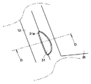
第2の筐体12のうち、折り畳んだ状態で第1の筐体11の凹部21に対向する部位の周辺(図1にBで示す)を拡大して図4に示す。第2の筐体12の前面のうち凹部21に対向する部位には、側面に達する凹部31が設けられている。凹部31も楕円体の一部分の如き形状であり、前方から見た凹部31の縁(凹部31と筐体12の前面との交線)は弧状であり、側方から見た凹部31の縁(凹部31と筐体12の側面との交線)も弧状である。また、凹部31の縁の近傍31aは、筐体12の前面や側面に対する角度を小さくする傾斜面とされている。
FIG. 4 shows an enlarged view of the periphery of the portion of the
図4の線D−Dでの断面を図5に示す。第1の筐体11の凹部21と異なり、第2の筐体12の凹部31の内部には何も配置されていない。
FIG. 5 shows a cross section taken along line DD in FIG. Unlike the
携帯電話機1が折り畳んだ状態にあるとき、第1の筐体11の凹部21と第2の筐体12の凹部31は、側面に開口を有する穴を形成する。この穴は、使用者が片手のみで携帯電話機1を開いた状態とするために利用される。使用者が片手で携帯電話機1を開いた状態とする過程を図6〜図10に示す。
When the
使用者はまず、図6に示すように、閉じた状態にある携帯電話機1の第1の筐体11を親指の付け根と他の指とで左右から挟み、親指Tの先端を側面の開口から穴の内部に挿入する。図6の線E−Eでの断面を図7に示す。親指Tの先端は、その腹が凹部21内の回動体22の傾斜面22aに触れ、背(爪)が凹部31の面に触れる。
First, as shown in FIG. 6, the user sandwiches the
使用者はその状態から、図8に示すように、親指Tをさらに深く挿入する。図8の線F−Fでの断面を図9に示す。回動体22は、親指Tの腹で押されて背面側に回動し、凹部22の深部の底面(不図示)に当接して停止する。このとき、第2の筐体12は親指Tの背により第1の筐体11から離間する方向の力を受けて、ある程度回動する。
From that state, the user inserts the thumb T deeper as shown in FIG. FIG. 9 shows a cross section taken along line FF in FIG. The rotating
使用者は次いで、親指Tの背で第2の筐体12に第1の筐体11から離間する方向の力を加えて、第2の筐体12を大きく回動させ、さらに、図10に示すように、親指Tの側部で第2の筐体12に第1の筐体11から離間する方向の力を加えて、第2の筐体12を一層回動させる。これで、携帯電話機1は開いた状態となる。なお、図10において、丸で囲んだX印は、紙面の背面側に向けて力を加えることを表している。
Next, the user applies a force in the direction away from the
上述のように、携帯電話機1を開く操作は手指の自然な動きのみで成り立っており、携帯電話機1を片手のみで折り畳んだ状態から開いた状態にすることは容易である。凹部21、31の縁近傍21a、31aは傾斜面とされて、側面に対する角度が小さくなっているため、親指Tの先端を開口から穴に挿入するときに、開口の尖った縁に指先が当たって使用者が苦痛を感じることはないし、挿入も円滑に行うことができる。また、開いた状態でも、凹部21、31は筐体11、12の前面や側面に概ねなだらかに連なり、尖った縁が手指や顔に触れて使用者が苦痛を感じることはない。
As described above, the operation of opening the
さらに、凹部21、31を楕円体の一部分の如き形状として、側面での凹部21、31の縁を弧状としているため、側面に形成される開口を、親指の挿入が可能な必要最小の大きさとすることができる。しかも、回動体22を設けているため、開口を介して見えるのは穴の一部分のみである。したがって、片手で開いた状態とし得るようにするために凹部21、31を設けたことで、携帯電話機1の美観が損なわれることはない。
Further, since the
なお、当然ながら、従来のように、両手を用いて携帯電話機1を折り畳んだ状態から開いた状態にすることも可能である。
Needless to say, it is possible to change the
第2の実施形態の折り畳み式携帯電話機2の開いた状態での外観を図11に示す。この携帯電話機2は、第1の実施形態の携帯電話機1を修飾して、第2の筐体12の前面に凹部31を取り囲む凸部を設けたものである。他の構成は携帯電話機1と同様なので、重複する説明は省略する。
FIG. 11 shows an external appearance of the foldable
凹部31の周辺(図11にBで示す)を拡大して図12に示し、図12の線D−Dでの断面を図13に示す。第2の筐体12の前面には凹部31を取り囲む凸部32が設けられている。凸部32は、凹部31と第2の筐体12の前面に設けられている表示部15との間に位置する。凸部32は、側面から離れるほど第2の筐体12の前面から離れる傾斜面を有しており、表示部15寄りの端部で最も高くなっている。
FIG. 12 is an enlarged view of the periphery of the recess 31 (indicated by B in FIG. 11), and FIG. 13 shows a cross section taken along line DD in FIG. A
前述の図6〜図10に示した操作を行う際、親指Tを穴に深く挿入しすぎると、親指Tが表示部15に触れて、表示部15に汚れが付着することがある。また、穴への挿入に際しては親指Tの背が第2の筐体12側を向くから、親指Tの爪で表示部15を損傷するおそれもある。
When performing the operations shown in FIGS. 6 to 10 described above, if the thumb T is inserted too deeply into the hole, the thumb T may touch the
しかしながら、本実施形態の折り畳み式携帯電話機2のように、凹部31を取り囲む凸部32を第2の筐体12の前面に設けておけば、親指Tを深く挿入しすぎたときでも、親指Tは凸部32に触れることになって、凸部32と高低差のある表示部15には触れない。したがって、表示部15が汚れたり損傷したりするのを確実に防止することができる。
However, if the
なお、図には示していないが、凸部32は手指や顔に触れることがあるため、凸部32の縁や角には適度な丸みをもたせておくのが望ましい。
Although not shown in the drawing, since the
上記の各実施形態では使用者が左手で把持する折り畳み式携帯電話1、2を掲げたが、前方から見て右側の側部に凹部21、31や回動体22を設けて、使用者が右手で把持する設定としてもよい。また、左側の側部と右側の側部の双方に凹部21、31や回動体22を設けて、任意の手で把持し、その手で開いた状態とし得るようにしてもよい。
In each of the above embodiments, the foldable
1、2 折り畳み式携帯電話機
11 第1の筐体
12 第2の筐体
13 ヒンジ部
14 キー
15 表示部
21 凹部
21a 凹部縁部
22 回動体
22a 回動体傾斜面
23 回動軸
24 板ばね
31 凹部
31a 凹部縁部
32 凸部
DESCRIPTION OF
Claims (4)
第1の筐体が、前面のうち使用時に親指の近傍となる部位に、側面に達する凹部を有し、
第2の筐体が、前面のうち折り畳んだ状態で第1の筐体の凹部に対向する部位に、側面に達する凹部を有し、
第1の筐体の凹部内に、側面から遠い側の端部付近に位置し上下方向に延びる回動軸を中心に回動可能で、側面に近いほど背面に近づく傾斜面を有する回動体と、その回動体を前方に付勢する付勢部材を備える
ことを特徴とする折り畳み式携帯電話機。 The first casing and the second casing, which are substantially equal in size in the left-right direction, extend in the left-right direction that rotatably connects the upper end of the first casing and the lower end of the second casing. A folded state provided with a rotation shaft, wherein the front surface of the first housing and the front surface of the second housing face each other, and an open state where the front surface of the first housing and the front surface of the second housing do not face each other And a folding mobile phone that is used by holding the first housing in the open state, with the first housing and the second housing attached in a direction approaching each other in the folded state. In what has a biasing mechanism
The first housing has a concave portion that reaches the side surface in a portion of the front surface that is near the thumb when in use,
The second housing has a concave portion reaching the side surface at a portion facing the concave portion of the first housing in a folded state of the front surface,
A rotating body having an inclined surface in the recess of the first housing, which can be rotated around a rotation shaft extending in the vertical direction and located near an end far from the side surface, and closer to the back surface as it is closer to the side surface; A foldable mobile phone comprising a biasing member that biases the rotating body forward.
第2の筐体が、前面のうち凹部の周囲に、凸部を有する
ことを特徴とする請求項1から請求項3までのいずれか1項に記載の折り畳み式携帯電話機。 A display unit is provided on the front surface of the second housing,
The foldable mobile phone according to any one of claims 1 to 3, wherein the second casing has a convex portion around the concave portion of the front surface.
Priority Applications (1)
| Application Number | Priority Date | Filing Date | Title |
|---|---|---|---|
| JP2004240282A JP2006060516A (en) | 2004-08-20 | 2004-08-20 | Foldable mobile phone |
Applications Claiming Priority (1)
| Application Number | Priority Date | Filing Date | Title |
|---|---|---|---|
| JP2004240282A JP2006060516A (en) | 2004-08-20 | 2004-08-20 | Foldable mobile phone |
Publications (1)
| Publication Number | Publication Date |
|---|---|
| JP2006060516A true JP2006060516A (en) | 2006-03-02 |
Family
ID=36107632
Family Applications (1)
| Application Number | Title | Priority Date | Filing Date |
|---|---|---|---|
| JP2004240282A Pending JP2006060516A (en) | 2004-08-20 | 2004-08-20 | Foldable mobile phone |
Country Status (1)
| Country | Link |
|---|---|
| JP (1) | JP2006060516A (en) |
Cited By (11)
| Publication number | Priority date | Publication date | Assignee | Title |
|---|---|---|---|---|
| JP2008182343A (en) * | 2007-01-23 | 2008-08-07 | Casio Hitachi Mobile Communications Co Ltd | Folding type mobile terminal device |
| JP2010250513A (en) * | 2009-04-14 | 2010-11-04 | Fujitsu Ltd | Electronics |
| US8384770B2 (en) | 2010-06-02 | 2013-02-26 | Nintendo Co., Ltd. | Image display system, image display apparatus, and image display method |
| US8512152B2 (en) | 2010-06-11 | 2013-08-20 | Nintendo Co., Ltd. | Hand-held game apparatus and housing part of the same |
| US8633947B2 (en) | 2010-06-02 | 2014-01-21 | Nintendo Co., Ltd. | Computer-readable storage medium having stored therein information processing program, information processing apparatus, information processing system, and information processing method |
| US8780183B2 (en) | 2010-06-11 | 2014-07-15 | Nintendo Co., Ltd. | Computer-readable storage medium, image display apparatus, image display system, and image display method |
| US8854356B2 (en) | 2010-09-28 | 2014-10-07 | Nintendo Co., Ltd. | Storage medium having stored therein image processing program, image processing apparatus, image processing system, and image processing method |
| US8894486B2 (en) | 2010-01-14 | 2014-11-25 | Nintendo Co., Ltd. | Handheld information processing apparatus and handheld game apparatus |
| US9128293B2 (en) | 2010-01-14 | 2015-09-08 | Nintendo Co., Ltd. | Computer-readable storage medium having stored therein display control program, display control apparatus, display control system, and display control method |
| US9278281B2 (en) | 2010-09-27 | 2016-03-08 | Nintendo Co., Ltd. | Computer-readable storage medium, information processing apparatus, information processing system, and information processing method |
| US10506218B2 (en) | 2010-03-12 | 2019-12-10 | Nintendo Co., Ltd. | Computer-readable storage medium having stored therein display control program, display control apparatus, display control system, and display control method |
-
2004
- 2004-08-20 JP JP2004240282A patent/JP2006060516A/en active Pending
Cited By (14)
| Publication number | Priority date | Publication date | Assignee | Title |
|---|---|---|---|---|
| JP2008182343A (en) * | 2007-01-23 | 2008-08-07 | Casio Hitachi Mobile Communications Co Ltd | Folding type mobile terminal device |
| JP2010250513A (en) * | 2009-04-14 | 2010-11-04 | Fujitsu Ltd | Electronics |
| US8894486B2 (en) | 2010-01-14 | 2014-11-25 | Nintendo Co., Ltd. | Handheld information processing apparatus and handheld game apparatus |
| US9128293B2 (en) | 2010-01-14 | 2015-09-08 | Nintendo Co., Ltd. | Computer-readable storage medium having stored therein display control program, display control apparatus, display control system, and display control method |
| US10764565B2 (en) | 2010-03-12 | 2020-09-01 | Nintendo Co., Ltd. | Computer-readable storage medium having stored therein display control program, display control apparatus, display control system, and display control method |
| US10506218B2 (en) | 2010-03-12 | 2019-12-10 | Nintendo Co., Ltd. | Computer-readable storage medium having stored therein display control program, display control apparatus, display control system, and display control method |
| US9282319B2 (en) | 2010-06-02 | 2016-03-08 | Nintendo Co., Ltd. | Image display system, image display apparatus, and image display method |
| US8384770B2 (en) | 2010-06-02 | 2013-02-26 | Nintendo Co., Ltd. | Image display system, image display apparatus, and image display method |
| US8633947B2 (en) | 2010-06-02 | 2014-01-21 | Nintendo Co., Ltd. | Computer-readable storage medium having stored therein information processing program, information processing apparatus, information processing system, and information processing method |
| US8512152B2 (en) | 2010-06-11 | 2013-08-20 | Nintendo Co., Ltd. | Hand-held game apparatus and housing part of the same |
| US10015473B2 (en) | 2010-06-11 | 2018-07-03 | Nintendo Co., Ltd. | Computer-readable storage medium, image display apparatus, image display system, and image display method |
| US8780183B2 (en) | 2010-06-11 | 2014-07-15 | Nintendo Co., Ltd. | Computer-readable storage medium, image display apparatus, image display system, and image display method |
| US9278281B2 (en) | 2010-09-27 | 2016-03-08 | Nintendo Co., Ltd. | Computer-readable storage medium, information processing apparatus, information processing system, and information processing method |
| US8854356B2 (en) | 2010-09-28 | 2014-10-07 | Nintendo Co., Ltd. | Storage medium having stored therein image processing program, image processing apparatus, image processing system, and image processing method |
Similar Documents
| Publication | Publication Date | Title |
|---|---|---|
| US6996424B2 (en) | Portable, foldable electronic device comprising at least two use positions | |
| US7447527B2 (en) | Handheld electronic data processing device with multiple operation modes for different functions | |
| CN100385804C (en) | Self-operating opening mechanism for use in hand-held electronic devices | |
| US20040204197A1 (en) | Portable information terminal having expandable data input unit | |
| KR20060122932A (en) | Mobile communication devices | |
| EP1178649A2 (en) | Key and button arrangement for a portable, foldable electronic device comprising at least two use positions | |
| JP2006060516A (en) | Foldable mobile phone | |
| TWM249125U (en) | Handheld electronic device | |
| KR20120118352A (en) | Mobile terminal | |
| CN100342309C (en) | Data input key for a portable apparatus and key array thereof | |
| CN103237103A (en) | Sliding device for portable terminal and portable terminal | |
| JP2009088667A (en) | Portable device | |
| JP2006060517A (en) | Foldable mobile phone | |
| CN103081447B (en) | Slider for electronic equipment | |
| JP4026506B2 (en) | Switchgear and electronic device using the same | |
| JP2005534237A (en) | Automatic opening mechanism for electronic devices | |
| KR101155196B1 (en) | Port cover of portable terminal | |
| KR20060038552A (en) | Input device of portable terminal | |
| JP3111467B2 (en) | Flip phone | |
| JP2003298711A (en) | Fingerprint sensor reading unit composite shape for portable telephone | |
| KR200193785Y1 (en) | Mouse for note-book | |
| KR20040015475A (en) | Information and voice processing portable terminal structure having PDA and phone functions | |
| KR200230378Y1 (en) | Double cover of mobile communication apparatus | |
| KR100374356B1 (en) | Portable radiotelephone for game | |
| JP4403865B2 (en) | Switchgear |