JP2005529763A - Nail gun - Google Patents
Nail gun Download PDFInfo
- Publication number
- JP2005529763A JP2005529763A JP2004523722A JP2004523722A JP2005529763A JP 2005529763 A JP2005529763 A JP 2005529763A JP 2004523722 A JP2004523722 A JP 2004523722A JP 2004523722 A JP2004523722 A JP 2004523722A JP 2005529763 A JP2005529763 A JP 2005529763A
- Authority
- JP
- Japan
- Prior art keywords
- power
- locking device
- lock block
- nail gun
- push button
- Prior art date
- Legal status (The legal status is an assumption and is not a legal conclusion. Google has not performed a legal analysis and makes no representation as to the accuracy of the status listed.)
- Pending
Links
- 230000005540 biological transmission Effects 0.000 claims abstract description 23
- 238000011084 recovery Methods 0.000 description 5
- 238000013461 design Methods 0.000 description 4
- 230000008859 change Effects 0.000 description 3
- 238000005516 engineering process Methods 0.000 description 3
- 230000004308 accommodation Effects 0.000 description 2
- 238000010586 diagram Methods 0.000 description 2
- 230000006872 improvement Effects 0.000 description 2
- 230000004048 modification Effects 0.000 description 2
- 238000012986 modification Methods 0.000 description 2
- 230000002093 peripheral effect Effects 0.000 description 2
- 230000009471 action Effects 0.000 description 1
- 238000004891 communication Methods 0.000 description 1
- 230000006835 compression Effects 0.000 description 1
- 238000007906 compression Methods 0.000 description 1
- 230000007547 defect Effects 0.000 description 1
- 238000003780 insertion Methods 0.000 description 1
- 230000037431 insertion Effects 0.000 description 1
- 238000000034 method Methods 0.000 description 1
- 230000008569 process Effects 0.000 description 1
- 230000009467 reduction Effects 0.000 description 1
- 230000004044 response Effects 0.000 description 1
Images


Classifications
-
- B—PERFORMING OPERATIONS; TRANSPORTING
- B25—HAND TOOLS; PORTABLE POWER-DRIVEN TOOLS; MANIPULATORS
- B25C—HAND-HELD NAILING OR STAPLING TOOLS; MANUALLY OPERATED PORTABLE STAPLING TOOLS
- B25C5/00—Manually operated portable stapling tools; Hand-held power-operated stapling tools; Staple feeding devices therefor
- B25C5/10—Driving means
- B25C5/15—Driving means operated by electric power
-
- B—PERFORMING OPERATIONS; TRANSPORTING
- B25—HAND TOOLS; PORTABLE POWER-DRIVEN TOOLS; MANIPULATORS
- B25C—HAND-HELD NAILING OR STAPLING TOOLS; MANUALLY OPERATED PORTABLE STAPLING TOOLS
- B25C1/00—Hand-held nailing tools; Nail feeding devices
- B25C1/06—Hand-held nailing tools; Nail feeding devices operated by electric power
Landscapes
- Engineering & Computer Science (AREA)
- Mechanical Engineering (AREA)
- Portable Nailing Machines And Staplers (AREA)
Abstract
動力装置が電源と二つの電源スイッチを具え、伝動装置はモータ、伝動歯車及び作動歯車を具え動力装置の駆動を受け、作動歯車は一部に作動歯を有し、制御装置は二つの押しボタン、係止装置、ロックブロックを具え、二つの押しボタンが押圧される時、動力装置と伝動装置を駆動し係止装置がロックブロックの押圧を受け外に移動し、衝撃装置は衝撃筒、撃板、及び弾性部品を具え、弾性部品の弾力開放時に撃板が釘列を押し出し、且つ衝撃筒が作動歯車の作動歯により駆動され、動力導通時に作動歯車の駆動により衝撃筒が後退し、作動歯が衝撃筒に噛み合わなくなる時、衝撃筒が前に釘列を押し出し、係止装置が作動歯車のプッシュロッドに押されロックブロックの係止を離脱し、位置を回復し電力切断し、その後、一つの押しボタンを開放すると、ロックブロックが再び係止装置を係止する。The power unit includes a power source and two power switches, the transmission unit includes a motor, a transmission gear, and an operating gear, and is driven by the power unit. The operating gear partially includes operating teeth, and the control unit includes two push buttons. When the two push buttons are pressed, the power device and the transmission device are driven, and the locking device moves to the outside under the pressure of the lock block. Plate and elastic parts, the impact plate pushes out the nail train when the elastic part is released, and the impact cylinder is driven by the operating teeth of the operating gear. When the tooth stops engaging with the impact cylinder, the impact cylinder pushes the nail row forward, the locking device is pushed by the push rod of the operating gear to release the lock block, recovers the position and disconnects power, One push button Upon release of the lock block to again lock the locking device.
Description
本発明は一種のネイルガンに係り、特に、一部に作動歯を有する作動歯車が衝撃筒に噛み合うか否かにより、衝撃筒の後退と回復を制御する設計と、動力装置、制御装置の組合せにより、構造が簡単で、機能が増されたネイルガンの構造に関する。 The present invention relates to a kind of nail gun, and in particular, by a combination of a power unit and a control device, a design for controlling the retraction and recovery of an impact cylinder depending on whether or not an operating gear partially having an operating tooth meshes with the impact cylinder. It relates to the structure of a nail gun with a simple structure and increased functions.
市場の競争が激烈となり、各種の工業技術が日々進歩するなかにあって、各メーカーは不断に研究開発を行ない、既存の製品の技術領域を突破して市場を占有するチャンスを狙っている。このため周知のネイルガンについても、業界が製造する構造には多くの形式があり、且つそれぞれに機能訴求、構造の創意を有しているが、その最大の欠点は現在のネイルガンの動力ソースは気動方式とされ、その設備は空気圧縮機と空気パイプをネイルガンに接続しなければならず、ゆえに周辺設備が多くなり、且つ使用、携帯上の不便を形成することであり、特に、施工場所を変換する時、一般家庭内では空気圧縮機等の設備をおけないためネイルガンは一般家庭では使用できず、このため常に変化が求められる市場での競争にあって、更に新規で、簡単で、周知の欠点を改善し、機能が増されその競争力を増さねば勝利のチャンスはない。 As the competition in the market intensifies and various industrial technologies advance day by day, manufacturers are constantly researching and developing, aiming to break through the technological field of existing products and occupy the market. For this reason, there are many types of structures manufactured by the industry for well-known nail guns, and each has its own appeal for function and structure, but the biggest drawback is the power source of current nail guns. It is necessary to connect an air compressor and an air pipe to the nail gun, so that the peripheral equipment is increased and inconvenience in use and portability is formed. When converting, nail guns cannot be used in ordinary households because they cannot be installed in ordinary households, so they are constantly in competition in the market where changes are required, and are new, simple, and well-known. There is no chance of victory if the defect is improved, the function is increased and the competitiveness is increased.
本発明は周知の技術の気動方式を電動方式に改変し、且つ最も好ましくは無線式の電動方式とし、その使用、携帯の便利性を増す。ゆえに、本発明の主要な目的は、使用に便利で、構造が簡単で、機能が増され、進歩性を有する一種の斬新な構造の電動ネイルガンを提供することにある。 The present invention modifies the known pneumatic system to an electric system, and most preferably a wireless electric system, increasing the convenience of use and portability. Therefore, the main object of the present invention is to provide an electric nail gun having a novel structure which is convenient to use, simple in structure, increased in function and has an inventive step.
本発明は、ケース、動力装置、伝動装置、制御装置及び衝撃装置で構成されている。そのうち、動力装置は電源と少なくとも二つの電源スイッチを具え、電源は商用電源を電源コードで提供するか或いは二次電池とされ、伝動装置はモータ、伝動歯車及び作動歯車を具えて動力装置の駆動を受け、且つ作動歯車は一部だけに作動歯を有し、制御装置は二つの押しボタン、係止装置及びロックブロックを具え、二つの押しボタンが押圧される時、動力装置と伝動装置が駆動され、このとき、係止装置がロックブロックの押圧を受けて外に移動し、並びに作動歯車に別に設けられたプッシュロッドに歯車回転後に押圧され、且つ押圧されてロックブロックの係止より離脱して位置を回復し電力切断し、またその一つの押しボタンが押圧されないと、ロックブロックが再び係止装置を係止して原状に回復し、これが反復して釘を打つロック係止構造の根拠とされ、衝撃装置は衝撃筒、撃板、及び弾性部品を具え、弾性部品が衝撃筒内に設けられ、それが弾力開放に撃板により釘列を押し出し、且つ衝撃筒が作動歯車の作動歯により駆動され、これにより動力導通時に作動歯車の駆動により衝撃筒が後退し、作動歯が衝撃筒に噛み合わない時、衝撃筒が前に釘列を押し出し、係止装置が作動歯車のプッシュロッドに押されてロックブロックの係止を離脱し、位置を回復し電力切断し、その後、更に一つの押しボタンを開放すると、ロックブロックが再び係止装置を係止して原状を回復し、こうして構造が簡単で新規な電動ネイルガン構造が形成される。 The present invention includes a case, a power device, a transmission device, a control device, and an impact device. Among them, the power unit includes a power source and at least two power switches, and the power source provides a commercial power source with a power cord or a secondary battery, and the transmission unit includes a motor, a transmission gear, and an operating gear to drive the power unit. The control gear has two push buttons, a locking device and a lock block, and when the two push buttons are pressed, the power device and the transmission device are Driven at this time, the locking device receives the pressure of the lock block and moves to the outside, and is pressed by the push rod provided separately to the operating gear after the gear rotation and is released from the lock block locking. Then the position is restored and the power is cut, and if one of the pushbuttons is not pressed, the lock block again locks the locking device and restores its original shape, which repeatedly hits the nail The impact device has an impact cylinder, a striking plate, and an elastic part, and the elastic part is provided in the impact cylinder, which pushes the nail row by the striking plate to release elasticity, and the impact. When the cylinder is driven by the operating tooth of the operating gear, the impact cylinder is retracted by the driving of the operating gear when power is turned on, and when the operating tooth does not mesh with the impact cylinder, the impact cylinder pushes the nail row forward, and the locking device Is pushed by the push rod of the operating gear to release the locking of the lock block, recovers the position and disconnects the power, and then when one more push button is released, the lock block locks the locking device again. The original state is restored, and thus a new electric nail gun structure having a simple structure is formed.
本発明の主要な目的は、斬新なネイルガン構造を提供することにあり、それは動力に電動方式を採用し、商用電源を電線で導入するか或いは二次電池を使用し、且つ構造が簡単で、衝撃装置の作動が平穏で確実であり、構造品質を確保できる進歩性を具備するものとする。 The main object of the present invention is to provide a novel nail gun structure, which adopts an electric system for power, introduces a commercial power source with an electric wire or uses a secondary battery, and has a simple structure, It is assumed that the operation of the impact device is calm and reliable, and has an inventive step capable of ensuring structural quality.
請求項1の発明は、ケース、動力装置、伝動装置、制御装置及び衝撃装置で構成され、 該ケースは、使用者の手部が通され握持に供される穿孔を具え、ケース内部は部品の収容或いは固定に供され、その出釘側に収容溝が設けられて釘列と釘列を押す弾性部品が収容され、且つケースに案内室が設けられ、
該動力装置は、電源と第1電源スイッチ、第2電源スイッチの少なくとも二つの電源スイッチを具え、二つの電源スイッチがそれぞれ突出接触部を具え、
該伝動装置は、モータ、伝動歯車セット及び作動歯車を具え、モータは動力装置に接続され、伝動歯車セットはモータに駆動されて作動歯車を駆動し、且つ作動歯車が一部に作動歯を具え、
該制御装置は、少なくとも第1押しボタン、第2押しボタンの二つの押しボタン、及び係止装置及びロックブロックを具え、第1押しボタンが押圧される時、第1電源スイッチの突出接触部を押圧して導通状態を形成し、第2押しボタンはロックブロックを弾性部品と共に収容してロックブロックを弾性突出可能とし、該係止装置は長孔を具えて該長孔がケース内部に延設さえた軸柱の挿通に供され、該軸柱が長孔行程を移動可能とされ、また係止装置のロックブロックに対応する側に係止孔が設けられてロックブロックが進入し、第2押しボタンが押圧される時、係止装置がロックブロックの押し上げにより移動し、且つ別の弾性部品の牽引を受け、係止装置が未だ押動を受けない時、弾性部品の牽引により第2電源スイッチが停電状態を保持し、且つ係止装置が外に押される時、第2電源スイッチが導通し、
該衝撃装置は、ケースの案内室内に設けられ、少なくとも衝撃筒、撃板、弾性部品を具え、弾性部品の一側が衝撃筒内に設けられ、別側はケースの案内室の後側内壁に当接し、衝撃筒の前端に撃板が固定され、弾性部品が弾性開放する時撃板により釘列を打撃し、衝撃筒に貫通溝に対応してラックが設けられ、且つラックが作動歯車の作動歯の駆動を受け、
以上により、第1押しボタンと第2押しボタンが押圧されて係止装置がロックブロックの押し上げにより移動して動力を導通させる時、作動歯車が回転し、その作動歯が衝撃筒のラックに噛み合い、衝撃筒が前に打撃して撃板により釘列を押し出すことを特徴とする、ネイルガンとしている。
請求項2の発明は、請求項1記載のネイルガンにおいて、第1押しボタン、第2押しボタンとケース内部の間に弾性体が設けられ、それが未押圧時に外向きに支持され、且つ第2電源スイッチの突出接触部が押圧される時、停電状態とされ、且つ係止装置が常態に回復する時、弾性部品の牽引により第2電源スイッチの突出接触部が押圧されることを特徴とする、ネイルガンとしている。
請求項3の発明は、請求項2記載のネイルガンにおいて、係止装置が湾曲部分を具え、長孔が該湾曲部分に設けられ、ロックブロックが斜め案内部を具え、且つ作動歯車の側面にプッシュロッドが設けられ、作動歯車が回転してそのプッシュロッドが係止装置を押圧する時、係止装置が長孔部分を軸心として回転し、係止孔がロックブロックの係止より離脱し、且つ弾性部品の牽引を受けた後に係止装置が回復して第2電源スイッチの突出接触部に接触して停電し、プッシュロッドが回転して係止装置を押圧しなくなると、係止装置がそれ以上回転せず、第2押しボタンを押圧せず、ロックブロックがその斜め案内部の案内により係止孔中に導入されて係止を回復することを特徴とする、ネイルガンとしている。
請求項4の発明は、請求項1記載のネイルガンにおいて、案内室の底側に貫通溝が設けられて衝撃筒のラックが挿通することを特徴とする、ネイルガンとしている。
請求項5の発明は、請求項1記載のネイルガンにおいて、電源が電線電源とされるか二次電池とされたことを特徴とする、ネイルガンとしている。
請求項6の発明は、請求項1記載のネイルガンにおいて、作動歯車の作動歯が半環部分に設けられたことを特徴とする、ネイルガンとしている。
請求項7の発明は、請求項1記載のネイルガンにおいて、第2押しボタンに収容室が設けられ、且つ収容室に弾性部品が設けられてロックブロックがこの弾性部品の上方に収容されて弾性突出可能とされたことを特徴とする、ネイルガンとしている。
請求項8の発明は、請求項1記載のネイルガンにおいて、ケースにあって衝撃装置の前端部分に収容孔が設けられ、収容孔内に接触ロッドが設けられ、該接触ロッドが弾性部品に付勢され、圧力を受けない時に常態でケースより突出し、接触ロッド内端に押し棒が設けられ、別に第3電源スイッチが設けられ、該第3電源スイッチに突出接触部が設けられてそれに動力部品が接続され、且つ押し棒は接触ロッド18が外から内に押圧される時、第3電源スイッチの突出接触部を押圧し、導通を形成することを特徴とする、ネイルガンとしている。
請求項9の発明は、請求項1記載のネイルガンにおいて、衝撃装置の弾性部品の別側が当接片に接続され、該当接片にピンが通され、該ピンの外側に回転つまみが設けられたことを特徴とする、ネイルガンとしている。
The invention of
The power unit includes at least two power switches, ie, a power source, a first power switch, and a second power switch, and each of the two power switches includes a projecting contact portion.
The transmission device includes a motor, a transmission gear set, and an operating gear, the motor is connected to a power unit, the transmission gear set is driven by the motor to drive the operating gear, and the operating gear partially includes operating teeth. ,
The control device includes at least two push buttons, a first push button, a second push button, a locking device, and a lock block. When the first push button is pressed, the protruding contact portion of the first power switch is provided. The second push button accommodates the lock block together with the elastic part so that the lock block can be elastically protruded. The locking device has a long hole that extends into the case. The shaft column is inserted into the shaft column so that the shaft column can move through the long hole stroke, and a locking hole is provided on the side corresponding to the lock block of the locking device so that the lock block enters, and the second When the push button is pressed, the locking device moves when the lock block is pushed up and is pulled by another elastic component. When the locking device is not yet pushed, the second power source is pulled by the elastic component. The power switch Lifting and, and when the locking device is pushed out, the second power switch is turned on,
The impact device is provided in the guide chamber of the case, and includes at least an impact cylinder, a strike plate, and an elastic part. One side of the elastic part is provided in the impact cylinder, and the other side contacts the rear inner wall of the case guide chamber. When the striking plate is fixed to the front end of the impact cylinder and the elastic part is elastically released, the nail train is struck by the striking board, the rack is provided in the impact cylinder corresponding to the through groove, and the rack is operated by the operating gear. Under the drive of the teeth
As described above, when the first push button and the second push button are pressed and the locking device moves by pushing up the lock block to conduct power, the operating gear rotates and the operating teeth mesh with the rack of the impact cylinder. The nail gun is characterized in that the impact cylinder is struck in front and the nail train is pushed out by the striking plate.
According to a second aspect of the present invention, in the nail gun according to the first aspect, an elastic body is provided between the first push button, the second push button and the inside of the case, and the elastic body is supported outward when not pressed, and the second When the protruding contact portion of the power switch is pressed, a power failure state occurs, and when the locking device recovers to a normal state, the protruding contact portion of the second power switch is pressed by pulling the elastic part. , With a nail gun.
According to a third aspect of the present invention, in the nail gun according to the second aspect, the locking device has a curved portion, the long hole is provided in the curved portion, the lock block has an oblique guide portion, and is pushed onto the side surface of the operating gear. When the rod is provided and the operating gear rotates and the push rod presses the locking device, the locking device rotates around the elongated hole portion, and the locking hole is disengaged from the locking of the lock block, When the locking device recovers after receiving the pulling of the elastic part, contacts the protruding contact portion of the second power switch and a power failure occurs, and the push rod rotates to stop pressing the locking device, the locking device The nail gun is characterized in that it does not rotate any further, does not press the second push button, and the lock block is introduced into the lock hole by the guide of the oblique guide portion to recover the lock.
According to a fourth aspect of the present invention, in the nail gun according to the first aspect, a through groove is provided on the bottom side of the guide chamber and the rack of the impact cylinder is inserted.
A fifth aspect of the present invention is the nail gun according to the first aspect, wherein the power source is an electric wire power source or a secondary battery.
A sixth aspect of the present invention is the nail gun according to the first aspect, wherein the operating tooth of the operating gear is provided in the half ring portion.
According to a seventh aspect of the present invention, in the nail gun according to the first aspect, the second push button is provided with a storage chamber, the storage chamber is provided with an elastic part, and the lock block is stored above the elastic part and elastically protrudes. It is a nail gun characterized by being made possible.
According to an eighth aspect of the present invention, in the nail gun according to the first aspect, in the case, a housing hole is provided in a front end portion of the impact device, a contact rod is provided in the housing hole, and the contact rod biases the elastic part. When it is not subjected to pressure, it protrudes from the case in a normal state, a push rod is provided at the inner end of the contact rod, a third power switch is provided separately, a projecting contact portion is provided on the third power switch, and power components are The connected and push rod is a nail gun characterized in that when the
According to a ninth aspect of the present invention, in the nail gun according to the first aspect, the other side of the elastic part of the impact device is connected to the contact piece, a pin is passed through the corresponding contact piece, and a rotary knob is provided outside the pin. It is a nail gun characterized by that.
本発明は一種のネイルガンに係り、特に、一部に作動歯を有する作動歯車が衝撃筒に噛み合うか否かにより、衝撃筒の後退と回復を制御する設計と、動力装置、制御装置の組合せにより、構造が簡単で、機能が増されたネイルガンの構造を提供している。 The present invention relates to a kind of nail gun, and in particular, by a combination of a power unit and a control device, a design for controlling the retraction and recovery of an impact cylinder depending on whether or not an operating gear partially having an operating tooth meshes with the impact cylinder. It provides a nail gun structure with simple structure and increased functionality.
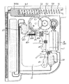
本発明は、ケース1、動力装置2、伝動装置3、制御装置4及び衝撃装置5で構成されている。
The present invention includes a
該ケース1は、使用者の手部が通され握持に供される穿孔11を具え、ケース1内部は部品の収容或いは固定に供され、その出釘側に収容溝12が設けられて釘列13と釘列13を押す弾性部品14が設けられ、且つケース1に案内室15が設けられ、該案内室15に衝撃装置5が収容され、案内室15の底側に貫通溝151が設けられている。
The
該動力装置2は、電源21と第1電源スイッチ22、第2電源スイッチ23の少なくとも二つの電源スイッチを具え、電源21は一般の電線電源(図2の如し)或いは二次電池(図1の如し)とされ得て、第1電源スイッチ22及び第2電源スイッチ23はいずれも電源21に接続され、且ついずれも感応部、例えば突出接触部221、231或いはその他の同じ機能を具備する構造を具え、第1電源スイッチ22の突出接触部221が押圧さされる時は導通状態とされ、第2電源スイッチ23の突出接触部231が押圧される時は電力切断状態とされる(これは周知の配線変化であり、本発明の主要な技術内容ではないため、説明を省略する。)。
The
伝動装置3は、モータ31、伝動歯車セット32及び作動歯車33を具え、モータ31は動力装置2に接続され、動力装置2の連通により作動し、伝動歯車セット32はモータ31に駆動され、且つ変速の機能を具え(また変速歯車セットと称され、この部分は減速用である)、伝動歯車セット32の最後が作動歯車33を駆動し、作動歯車33は一部に作動歯331を具え、図示される実施例では半環部分の歯を有し、また作動歯車33は側面に突出するプッシュロッド332を具えている。作動歯車33の作動歯331は衝撃装置5の衝撃筒51に作用してそれを後退させ、ゆえに歯数は要求される衝撃筒51の後退程度により定められ、図示される実施例では半環部に作動歯が設けられている。
The
制御装置4は少なくとも第1押しボタン41、第2押しボタン42の二つの押しボタン、及び一つの係止装置43及びロックブロック44を具えている。第1押しボタン41、第2押しボタン42はケース1の穿孔11の後端に設けられ、それとケース1内部の間に弾性体45が設けられ、それが未押圧時に、外向きの押圧状態を保持し、且つ第1押しボタン41が押圧される時、第1電源スイッチ22の突出接触部221を押圧し、それを導通状態となし(図3)、第2押しボタン42に収容室421が設けられ、且つ弾性部品422を収容し、並びにロックブロック44は斜め案内部441を具えている。別に係止装置43は湾曲部分を具えて例えばL形とされ、その湾曲部分に長孔431が設けられてケース1内部に延設された軸柱16が挿通し、係止装置43が長孔431の工程中を移動可能とされ、また係止装置43のロックブロック44に対応する側に係止孔432が設けられ、且つロックブロック44の挿通に適したものとされ、並びに第2押しボタン42が押圧される時、係止装置43がロックブロック44の押圧により移動し、且つ弾性部品433の牽引を受け(図3)、移動後に回復の弾性を具え、弾性部品433の一端は係止装置43に接続され、別端はケース1内部に接続されている。係止装置43が押動を受けない時、弾性部品433の牽引により第2電源スイッチ23の突出接触部231に対する押圧が保持され、これによりそれが電力切断状態を保持し(図1参照)、それがロックブロック44により外向きに押される時、第2電源スイッチ23が導通し(図3)、動力装置2が通電状態の時、作動歯車33が回転し、そのプッシュロッド332が係止装置43を押圧し、係止装置43が長孔431部分を軸として回転し(図5)、係止孔432がロックブロック44の係止より離脱し、弾性部品433の弾性回復力作用を受けて回復し第2電源スイッチ23の突出接触部231に圧接し電力を切断し、且つプッシュロッド332が係止装置43を押圧しなくなると、係止装置43はそれ以上回転しない(図6)。
The control device 4 includes at least two push buttons, a
衝撃装置5は、少なくとも衝撃筒51、撃板52、弾性部品53を具え、弾性部品53の一側が衝撃筒51内に設けられ、別側はケース1の案内室15の後側内壁に当接するか、或いは弾性部品53の別側が当接片54に当接し(図7)、当接片54に更にピン55が通されピン55の外側に回転ボタン551が設けられ、該回転ボタン551が弾性部品53の弾性力の調節に供される。衝撃筒51は案内室15内に設けられ、その前端に撃板52が固定され、弾性部品53が弾性開放する時撃板52により釘列12を打撃し、衝撃筒51に貫通溝151に対応してラック511が設けられ、且つラック511が貫通溝151を挿通した後に作動歯車33の作動歯331の駆動を受ける(図8参照)。
The
以上の構成により、実施時には、使用者は第1押しボタン41及び第2押しボタン42を押す(図3)。そのうち、係止装置43はロックブロック44に押圧されて移動し、且つ弾性部品433の牽引を受けて回復の弾性を得て、この時、その動力はすでに導通し、同時の作動歯車33が回転し、その作動歯331が衝撃筒51のラック511に噛み合う時、衝撃筒51を駆動して後退させ(図4)、この時、弾性部品533が弾性回復力を保存し、作動歯331がラック511と噛み合わなくなる時、瞬間的に衝撃筒51を前に打たせて撃板52により釘列13を押し出させ(図4)、こうして一次の釘打ちの操作を完成し、その後、作動歯車33が続けて回転し、そのプッシュロッド332が係止装置43を押圧する時、係止装置43が長孔431部分を軸心として回転し(図5)、係止孔432がロックブロック44の係止より離脱し、且つ弾性部品433の牽引により後退し第2電源スイッチ23の突出接触部231に圧接して電源を切断し、プッシュロッド332が係止装置43を押圧しなくなる時、係止装置43がそれ以上回転せず(図6)、使用者が第2押しボタン42を開放すると、ロックブロック44がその斜め案内部441を利用して係止孔432中に導入されて係止状態に回復し(図1)、一次作動の操作が完成する。
With the above configuration, at the time of implementation, the user presses the
更に、図7、8、9に示されるように、ケース1の衝撃装置5の前端部分に別に収容孔17が設けられ、該収容孔17内に接触ロッド18が枢設され、接触ロッド18に弾性部品19が嵌合され、圧迫されない時に状態でケース1より突出し、接触ロッド18の内端に押し棒10が固定され、更に第3電源スイッチ24が設けられ、それもまた突出接触部241を具えて動力装置2に接続され、且つ押し棒10が接触ロッド18が外から内に押圧される時(図11)、第3電源スイッチ24の突出接触部241を押圧し、導通を形成し、操作時に使用者が直接接触ロッド18の前端を釘打ち部分に押しつけると、第3電源スイッチ24が導通し、その後、前述と同様の操作プロセスの操作により、3つの電源スイッチの保険構造が構成される。
Further, as shown in FIGS. 7, 8, and 9, a
以上の構造設計及び改良を受け、本発明は、動力装置2、伝動装置3、制御装置4、及び衝撃装置5の組合せ構造により、少なくとも二つの電源スイッチのほか、作動歯車33、ラック511及び係止装置43、ロックブロック44の連動設計が本発明の構造の核心とされ、ネイルガンの構造の簡易化、衝撃筒の作動が平穏で確実とされ及び構造品質確保の進歩性目標を達成し、且つその動力が電力方式に改められて空気圧縮機の周辺設備を免除し、特に二次電池の利用により各種の作業場所、家庭での使用に適合し、且つ電線電源を採用して家庭生活中で使用でき、且つ現在DIY工具、製品の流行の下、その動力の心配がなく、取得しやすく、更に本発明の製品の進歩性が明らかであり、周知の技術と較べて技術上、明らかに進歩しており、ネイルガン製品に革命をもたらすものである。
In response to the structural design and improvement described above, the present invention is based on the combined structure of the
総合すると、本発明の新規な構造は産業上の利用性、新規性、進歩性を具え、特許の要件を具備している。なお、以上の実施例は本発明の範囲を限定するものではなく、本発明に基づきなしうる細部の修飾或いは改変は、いずれも本発明の請求範囲に属するものとする。 Taken together, the novel structure of the present invention has industrial applicability, novelty, inventive step and has patent requirements. It should be noted that the above embodiments do not limit the scope of the present invention, and any modification or modification of details that can be made based on the present invention shall belong to the claims of the present invention.
1 ケース 11 穿孔
12 収容溝 13 釘列
14 弾性部品 15 案内室
151 貫通溝 16 軸柱
17 収容孔 18 接触ロッド
19 弾性部品 10 押し棒
2 動力装置 21 電源
22 第1電源スイッチ 221 突出接触部
23 第2電源スイッチ 231 突出接触部
24 第3電源スイッチ 241 突出接触部
3 伝動装置 31 モータ
32 伝動歯車セット 33 作動歯車
331 作動歯 332 プッシュロッド
4 制御装置 41 第1押しボタン
42 第2押しボタン 421 収容室
422 弾性部品 43 係止装置
431 長孔 432 係止孔
433 弾性部品 44 ロックブロック
441 斜め案内部 45 弾性体
5 衝撃装置 51 衝撃筒
511 ラック 52 撃板
53 弾性部品 54 当接片
55 ピン 551 回転つまみ
DESCRIPTION OF
Claims (9)
該ケースは、使用者の手部が通され握持に供される穿孔を具え、ケース内部は部品の収容或いは固定に供され、その出釘側に収容溝が設けられて釘列と釘列を押す弾性部品が収容され、且つケースに案内室が設けられ、
該動力装置は、電源と第1電源スイッチ、第2電源スイッチの少なくとも二つの電源スイッチを具え、二つの電源スイッチがそれぞれ突出接触部を具え、
該伝動装置は、モータ、伝動歯車セット及び作動歯車を具え、モータは動力装置に接続され、伝動歯車セットはモータに駆動されて作動歯車を駆動し、且つ作動歯車が一部に作動歯を具え、
該制御装置は、少なくとも第1押しボタン、第2押しボタンの二つの押しボタン、及び係止装置及びロックブロックを具え、第1押しボタンが押圧される時、第1電源スイッチの突出接触部を押圧して導通状態を形成し、第2押しボタンはロックブロックを弾性部品と共に収容してロックブロックを弾性突出可能とし、該係止装置は長孔を具えて該長孔がケース内部に延設さえた軸柱の挿通に供され、該軸柱が長孔行程を移動可能とされ、また係止装置のロックブロックに対応する側に係止孔が設けられてロックブロックが進入し、第2押しボタンが押圧される時、係止装置がロックブロックの押し上げにより移動し、且つ別の弾性部品の牽引を受け、係止装置が未だ押動を受けない時、弾性部品の牽引により第2電源スイッチが停電状態を保持し、且つ係止装置が外に押される時、第2電源スイッチが導通し、
該衝撃装置は、ケースの案内室内に設けられ、少なくとも衝撃筒、撃板、弾性部品を具え、弾性部品の一側が衝撃筒内に設けられ、別側はケースの案内室の後側内壁に当接し、衝撃筒の前端に撃板が固定され、弾性部品が弾性開放する時撃板により釘列を打撃し、衝撃筒に貫通溝に対応してラックが設けられ、且つラックが作動歯車の作動歯の駆動を受け、
以上により、第1押しボタンと第2押しボタンが押圧されて係止装置がロックブロックの押し上げにより移動して動力を導通させる時、作動歯車が回転し、その作動歯が衝撃筒のラックに噛み合い、衝撃筒が前に打撃して撃板により釘列を押し出すことを特徴とする、ネイルガン。 Consists of case, power unit, transmission unit, control unit and impact unit,
The case is provided with a perforation through which a user's hand is passed and used for gripping, and the inside of the case is used for receiving or fixing parts, and a receiving groove is provided on the protruding nail side to provide a nail row and a nail row. Elastic parts that press the are housed, and a guide chamber is provided in the case,
The power unit includes at least two power switches, ie, a power source, a first power switch, and a second power switch, and each of the two power switches includes a projecting contact portion.
The transmission device includes a motor, a transmission gear set, and an operating gear, the motor is connected to a power unit, the transmission gear set is driven by the motor to drive the operating gear, and the operating gear partially includes operating teeth. ,
The control device includes at least two push buttons, a first push button, a second push button, a locking device, and a lock block. When the first push button is pressed, the protruding contact portion of the first power switch is provided. The second push button accommodates the lock block together with the elastic part so that the lock block can be elastically protruded. The locking device has a long hole that extends into the case. The shaft column is inserted into the shaft column so that the shaft column can move through the long hole stroke, and a locking hole is provided on the side corresponding to the lock block of the locking device so that the lock block enters, and the second When the push button is pressed, the locking device moves when the lock block is pushed up and is pulled by another elastic component. When the locking device is not yet pushed, the second power source is pulled by the elastic component. The power switch Lifting and, and when the locking device is pushed out, the second power switch is turned on,
The impact device is provided in the guide chamber of the case, and includes at least an impact cylinder, a strike plate, and an elastic part. One side of the elastic part is provided in the impact cylinder, and the other side contacts the rear inner wall of the case guide chamber. When the striking plate is fixed to the front end of the impact cylinder and the elastic part is elastically released, the nail train is struck by the striking board, the rack is provided in the impact cylinder corresponding to the through groove, and the rack is operated by the operating gear. Under the drive of the teeth
As described above, when the first push button and the second push button are pressed and the locking device moves by pushing up the lock block to conduct power, the operating gear rotates and the operating teeth mesh with the rack of the impact cylinder. The nail gun is characterized in that the impact cylinder is struck forward and the nail row is pushed out by the striking plate.
2. The nail gun according to claim 1, wherein another side of the elastic part of the impact device is connected to the contact piece, a pin is passed through the contact piece, and a rotary knob is provided outside the pin. .
Applications Claiming Priority (1)
| Application Number | Priority Date | Filing Date | Title |
|---|---|---|---|
| PCT/CN2002/000518 WO2004011201A1 (en) | 2002-07-25 | 2002-07-25 | A hand-held nailing tool |
Publications (1)
| Publication Number | Publication Date |
|---|---|
| JP2005529763A true JP2005529763A (en) | 2005-10-06 |
Family
ID=30774640
Family Applications (1)
| Application Number | Title | Priority Date | Filing Date |
|---|---|---|---|
| JP2004523722A Pending JP2005529763A (en) | 2002-07-25 | 2002-07-25 | Nail gun |
Country Status (9)
| Country | Link |
|---|---|
| US (1) | US6997367B2 (en) |
| JP (1) | JP2005529763A (en) |
| CN (1) | CN1308118C (en) |
| AU (1) | AU2002323786A1 (en) |
| CA (1) | CA2479979C (en) |
| DE (1) | DE10297712T5 (en) |
| GB (1) | GB2406070B (en) |
| MX (1) | MXPA05001027A (en) |
| WO (1) | WO2004011201A1 (en) |
Cited By (8)
| Publication number | Priority date | Publication date | Assignee | Title |
|---|---|---|---|---|
| JP2007260898A (en) * | 2006-03-28 | 2007-10-11 | Hilti Ag | Driving device |
| JP2008132590A (en) * | 2006-11-27 | 2008-06-12 | Hilti Ag | Fixed element driving device |
| JP2008279518A (en) * | 2007-05-08 | 2008-11-20 | Hitachi Koki Co Ltd | Driving machine |
| WO2015182508A1 (en) * | 2014-05-30 | 2015-12-03 | 日立工機株式会社 | Driving machine |
| JP2016068221A (en) * | 2014-09-30 | 2016-05-09 | 日立工機株式会社 | Driving machine |
| CN105818099A (en) * | 2016-05-26 | 2016-08-03 | 杭州科龙电器工具股份有限公司 | Electric nail gun using air spring |
| JP2016190277A (en) * | 2015-03-31 | 2016-11-10 | 日立工機株式会社 | Driving machine |
| CN114427749A (en) * | 2022-01-26 | 2022-05-03 | 黄曹 | Portable gas hot air gun |
Families Citing this family (86)
| Publication number | Priority date | Publication date | Assignee | Title |
|---|---|---|---|---|
| US8302833B2 (en) | 2004-04-02 | 2012-11-06 | Black & Decker Inc. | Power take off for cordless nailer |
| US10882172B2 (en) | 2004-04-02 | 2021-01-05 | Black & Decker, Inc. | Powered hand-held fastening tool |
| WO2005102611A2 (en) * | 2004-04-20 | 2005-11-03 | Acco Brands Usa Llc | Handheld powered stapler |
| CN100351047C (en) * | 2004-11-05 | 2007-11-28 | 茂纲实业股份有限公司 | Single-click electric nail gun |
| US20060180631A1 (en) * | 2005-02-16 | 2006-08-17 | Chris Pedicini | Electric motor driven energy storage device for impacting |
| DE102005016454A1 (en) * | 2005-04-11 | 2006-10-12 | Robert Bosch Gmbh | Hand tool for driving in staples and / or nails |
| US8505798B2 (en) | 2005-05-12 | 2013-08-13 | Stanley Fastening Systems, L.P. | Fastener driving device |
| US7938305B2 (en) * | 2006-05-31 | 2011-05-10 | Stanley Fastening Systems, L.P. | Fastener driving device |
| US7494037B2 (en) * | 2005-05-12 | 2009-02-24 | Stanley Fastening Systems, L.P. | Fastener driving device |
| DE102005000089B4 (en) * | 2005-07-13 | 2023-02-09 | Hilti Aktiengesellschaft | Hand-held fastener driving tool |
| JP4749828B2 (en) * | 2005-10-19 | 2011-08-17 | 株式会社マキタ | Driving tool |
| EP1777040B1 (en) * | 2005-10-19 | 2013-01-16 | Makita Corporation | Power tool |
| JP2007237351A (en) * | 2006-03-09 | 2007-09-20 | Hitachi Koki Co Ltd | Portable driving machine |
| JP2007237345A (en) * | 2006-03-09 | 2007-09-20 | Hitachi Koki Co Ltd | Portable driving machine |
| DE102006000202A1 (en) * | 2006-04-27 | 2007-11-08 | Hilti Ag | Hand-guided tacker |
| JP4664240B2 (en) * | 2006-06-12 | 2011-04-06 | 株式会社マキタ | Driving tool |
| US7322502B1 (en) * | 2006-07-25 | 2008-01-29 | Pei-Chang Sun | Protection device for DC-powered nail gun |
| JP4692932B2 (en) * | 2006-09-14 | 2011-06-01 | 日立工機株式会社 | Electric driving machine |
| DE102007000007A1 (en) * | 2007-01-11 | 2008-08-21 | Hilti Aktiengesellschaft | Hand-guided tacker |
| US20080190986A1 (en) * | 2007-02-09 | 2008-08-14 | Chin-Hsiung Chang | Electric Nailing Mechanism |
| JP5024727B2 (en) * | 2007-03-26 | 2012-09-12 | 日立工機株式会社 | Driving machine |
| JP4968518B2 (en) * | 2007-04-03 | 2012-07-04 | 日立工機株式会社 | Driving machine |
| TW200906566A (en) * | 2007-08-07 | 2009-02-16 | Nat Energy Technology Co Ltd | Electric tool |
| US7789282B2 (en) * | 2007-08-14 | 2010-09-07 | Chervon Limited | Nailer device |
| US20090057368A1 (en) * | 2007-08-27 | 2009-03-05 | Wen-Pin Lin | Impact-Force Adjusting Device for a Nailer |
| US7513407B1 (en) * | 2007-09-20 | 2009-04-07 | Acuman Power Tools Corp. | Counterforce-counteracting device for a nailer |
| US8763874B2 (en) * | 2007-10-05 | 2014-07-01 | Senco Brands, Inc. | Gas spring fastener driving tool with improved lifter and latch mechanisms |
| US8011441B2 (en) | 2007-10-05 | 2011-09-06 | Senco Brands, Inc. | Method for controlling a fastener driving tool using a gas spring |
| JP5146734B2 (en) * | 2008-01-15 | 2013-02-20 | 日立工機株式会社 | Fastener driving machine |
| JP5424009B2 (en) * | 2008-01-15 | 2014-02-26 | 日立工機株式会社 | Fastener driving machine |
| KR100914641B1 (en) * | 2008-04-10 | 2009-09-02 | 이재민 | Nail holding and hitting device |
| US20100116864A1 (en) * | 2008-11-07 | 2010-05-13 | Pneutools, Incorporated | Motorized fastener applicator |
| CN102844154B (en) * | 2010-02-19 | 2015-09-16 | 密尔沃基电动工具公司 | Percussion mechanism |
| DE102010030098A1 (en) * | 2010-06-15 | 2011-12-15 | Hilti Aktiengesellschaft | driving- |
| DE102011075882A1 (en) * | 2010-06-15 | 2011-12-15 | Hilti Aktiengesellschaft | driving- |
| TWI401143B (en) * | 2010-11-03 | 2013-07-11 | Basso Ind Corp | Electric nail gun double switch device |
| DE102010063176A1 (en) * | 2010-12-15 | 2012-06-21 | Hilti Aktiengesellschaft | Electrically operated bolt gun |
| JP5733051B2 (en) | 2011-06-24 | 2015-06-10 | マックス株式会社 | Electric driving tool |
| GB2483957B (en) * | 2011-07-20 | 2012-10-24 | Anthony Richard Howe | Cable clip gun |
| US20130240594A1 (en) * | 2012-03-19 | 2013-09-19 | Stanley Fastening Systems, L.P. | Cordless carton closer |
| CN102689289B (en) * | 2012-05-30 | 2014-12-17 | 杭州博达设计咨询有限公司 | Nail gun |
| US9676090B2 (en) * | 2012-06-21 | 2017-06-13 | Illinois Tool Works Inc. | Fastener-driving tool with an electric power generator |
| US9522463B2 (en) | 2012-07-25 | 2016-12-20 | Worktools Inc. | Compact electric spring energized desktop stapler |
| DE102012219288A1 (en) * | 2012-10-23 | 2014-04-24 | Hilti Aktiengesellschaft | Drive-in device with adjustable spring accumulator |
| DE102012221748A1 (en) * | 2012-11-28 | 2014-05-28 | Robert Bosch Gmbh | Hand tool |
| JP6309022B2 (en) * | 2012-12-21 | 2018-04-11 | アトラス・コプコ・インダストリアル・テクニーク・アクチボラグ | Impact wrench with push start function |
| US9643306B2 (en) * | 2014-04-15 | 2017-05-09 | Illinois Tool Works Inc. | Fastener-driving tool including a driving device |
| TWI607839B (en) | 2014-06-05 | 2017-12-11 | Basso Ind Corp | Portable power tool and impact block resetting device |
| TWI613049B (en) * | 2014-07-18 | 2018-02-01 | Basso Ind Corp | Portable power tool control method |
| US9636812B2 (en) * | 2015-01-23 | 2017-05-02 | Tricord Solutions, Inc. | Fastener driving apparatus |
| EP3253534B1 (en) * | 2015-02-06 | 2020-05-06 | Milwaukee Electric Tool Corporation | Gas spring-powered fastener driver |
| CN107249823A (en) * | 2015-02-26 | 2017-10-13 | 日立工机株式会社 | Beating machine |
| FI3888850T3 (en) | 2015-03-30 | 2024-09-23 | Kyocera Senco Industrial Tools Inc | Method and lift mechanism for framing nailer |
| JP6485544B2 (en) * | 2015-06-10 | 2019-03-20 | 工機ホールディングス株式会社 | Driving machine |
| US10363650B2 (en) * | 2015-11-05 | 2019-07-30 | Makita Corporation | Driving tool |
| TWM518764U (en) * | 2015-11-26 | 2016-03-11 | Yih Kai Entpr Co Ltd | Pneumatic toy gun bolt device |
| WO2018003370A1 (en) * | 2016-06-30 | 2018-01-04 | 日立工機株式会社 | Driving device |
| CN106112917B (en) * | 2016-08-20 | 2018-06-12 | 谢建华 | A kind of automatically upper nailing machine structure and automatic nailing gun |
| FI3558595T3 (en) | 2016-12-22 | 2023-12-14 | Kyocera Senco Industrial Tools Inc | FASTENER OPERATING TOOL WITH OPERATING DEVICE POSITION SENSORS |
| TWI714707B (en) * | 2017-01-18 | 2021-01-01 | 鑽全實業股份有限公司 | Unobstructed recovery device of electric nail gun |
| US10974378B2 (en) * | 2017-02-03 | 2021-04-13 | Tricord Solutions, Inc. | Fastener driving apparatus |
| JP7271438B2 (en) | 2017-05-03 | 2023-05-11 | シグノード インダストリアル グループ リミティド ライアビリティ カンパニー | electric stapling device |
| TWI744560B (en) * | 2017-11-02 | 2021-11-01 | 鑽全實業股份有限公司 | Pneumatic nail gun and its firing pin device |
| US10822880B2 (en) | 2018-01-25 | 2020-11-03 | Amy Knott | Golf tee insert device and method for inserting a golf tee into the ground |
| JP7050952B2 (en) | 2018-04-20 | 2022-04-08 | キョウセラ センコ インダストリアル ツールズ インク. | Improved lift mechanism for framing nailers |
| CA3106685C (en) | 2018-08-28 | 2023-12-05 | Kyocera Senco Industrial Tools, Inc. | Forced air cooling from piston movements of nailer tool |
| USD900575S1 (en) | 2018-09-26 | 2020-11-03 | Milwaukee Electric Tool Corporation | Powered fastener driver |
| US12194607B2 (en) | 2018-10-17 | 2025-01-14 | Kyocera Senco Industrial Tools, Inc. | Working cylinder for power tool with piston lubricating system |
| AU2019360114B2 (en) | 2018-10-17 | 2022-08-11 | Kyocera Senco Industrial Tools, Inc. | Working cylinder for power tool with piston lubricating system |
| CN109159439B (en) * | 2018-10-29 | 2023-09-22 | 梅胜旺 | Disassembly-free tire repairing gun for automobile vacuum tire |
| CN109392749A (en) * | 2018-11-30 | 2019-03-01 | 上海生物数据有限公司 | Electric ear tag gun |
| US10946547B2 (en) * | 2018-12-03 | 2021-03-16 | Apex Mfg. Co., Ltd. | Electric striking device |
| TW202134018A (en) * | 2020-03-04 | 2021-09-16 | 鑽全實業股份有限公司 | Electric nail gun with buffer mechanism |
| JP7332522B2 (en) * | 2020-03-31 | 2023-08-23 | 株式会社マキタ | driving tool |
| US11285593B2 (en) * | 2020-05-05 | 2022-03-29 | Apex Mfg. Co., Ltd. | Electric stapler |
| CA3174815A1 (en) | 2020-05-07 | 2021-11-11 | Kyocera Senco Industrial Tools, Inc. | Power driving tool with latch position sensor |
| WO2022094190A2 (en) | 2020-10-30 | 2022-05-05 | Milwaukee Electric Tool Corporation | Powered fastener driver |
| WO2023176711A1 (en) * | 2022-03-16 | 2023-09-21 | 工機ホールディングス株式会社 | Work machine |
| CN114670566B (en) * | 2022-03-18 | 2025-11-18 | 得力集团有限公司 | An electric stapler |
| WO2023205068A1 (en) | 2022-04-18 | 2023-10-26 | Kyocera Senco Industrial Tools, Inc. | Lifter for fastener driving tool |
| US12251807B2 (en) * | 2022-05-13 | 2025-03-18 | Makita Corporation | Driving tools |
| US12128535B2 (en) * | 2022-06-14 | 2024-10-29 | Taizhou Dajiang Ind. Co. Ltd. | Force supply mechanisms and nail guns having same |
| US12434365B2 (en) | 2022-07-15 | 2025-10-07 | Kyocera Senco Industrial Tools, Inc. | Microfastener driving tool with gas spring |
| WO2025111243A1 (en) * | 2023-11-21 | 2025-05-30 | Kyocera Senco Industrial Tools, Inc. | Lifter with shield for fastener driving tools |
| US20250229396A1 (en) * | 2024-01-12 | 2025-07-17 | Milwaukee Electric Tool Corporation | Gas spring-powered fastener driver |
| CN118080920B (en) * | 2024-04-17 | 2024-09-27 | 山东旭光汽配有限公司 | Automatic drilling equipment for machining automobile silencer |
Family Cites Families (16)
| Publication number | Priority date | Publication date | Assignee | Title |
|---|---|---|---|---|
| US4033500A (en) * | 1976-03-26 | 1977-07-05 | Electro-Matic Staplers, Inc. | Electromagnetic stapler and safety trigger therefor |
| US4049176A (en) * | 1976-05-11 | 1977-09-20 | Monarch Marking Systems, Inc. | Tag attaching apparatus |
| US4583600A (en) * | 1981-04-30 | 1986-04-22 | Black & Decker Inc. | Impact tool |
| DE3237616A1 (en) * | 1982-10-11 | 1984-04-12 | Hilti AG, 9494 Schaan | DRIVING DEVICE FOR NAILS AND THE LIKE FASTENING ELEMENTS |
| GB2171351B (en) * | 1985-02-27 | 1988-10-26 | Tench Main Limited | Fastener dispensing and affixing device |
| US4724992A (en) * | 1985-11-07 | 1988-02-16 | Olympic Company, Ltd. | Electric tacker |
| US4811885A (en) * | 1988-03-23 | 1989-03-14 | Lai Wen Tan | Power transmission mechanism of an electric stapler |
| US4834278A (en) * | 1988-06-13 | 1989-05-30 | Lin Chung Cheng | Structure of dc motorized nailing machine |
| CN2047208U (en) * | 1989-02-04 | 1989-11-08 | 蔡裕庆 | An electric nailing machine including automatic correction, power saving and safety devices |
| JPH07115307B2 (en) * | 1989-04-24 | 1995-12-13 | 株式会社マキタ | Electric tucker |
| US5004140A (en) * | 1989-04-24 | 1991-04-02 | Makita Electric Works, Ltd. | Electrically-operated tacker |
| AU637367B2 (en) * | 1990-04-24 | 1993-05-27 | Regitar Power Tools Co Ltd | A transmission mechanism for an electric stapling gun |
| CN2081783U (en) * | 1990-05-04 | 1991-07-31 | 蔡宜雄 | Double-cam transmission structure of electric nailing machine |
| JP2568736Y2 (en) * | 1993-12-06 | 1998-04-15 | マックス株式会社 | Portable electric staple driving machine |
| JP3676879B2 (en) * | 1995-07-25 | 2005-07-27 | 株式会社マキタ | Fastener driving tool |
| CN2419019Y (en) * | 2000-05-17 | 2001-02-14 | 吴鹏德 | Nail head device of nail box machine |
-
2002
- 2002-07-25 JP JP2004523722A patent/JP2005529763A/en active Pending
- 2002-07-25 CN CNB028285638A patent/CN1308118C/en not_active Expired - Fee Related
- 2002-07-25 US US10/506,261 patent/US6997367B2/en not_active Expired - Fee Related
- 2002-07-25 WO PCT/CN2002/000518 patent/WO2004011201A1/en not_active Ceased
- 2002-07-25 DE DE10297712T patent/DE10297712T5/en not_active Withdrawn
- 2002-07-25 GB GB0419998A patent/GB2406070B/en not_active Expired - Fee Related
- 2002-07-25 MX MXPA05001027A patent/MXPA05001027A/en unknown
- 2002-07-25 AU AU2002323786A patent/AU2002323786A1/en not_active Abandoned
- 2002-07-25 CA CA002479979A patent/CA2479979C/en not_active Expired - Fee Related
Cited By (11)
| Publication number | Priority date | Publication date | Assignee | Title |
|---|---|---|---|---|
| JP2007260898A (en) * | 2006-03-28 | 2007-10-11 | Hilti Ag | Driving device |
| JP2008132590A (en) * | 2006-11-27 | 2008-06-12 | Hilti Ag | Fixed element driving device |
| JP2008279518A (en) * | 2007-05-08 | 2008-11-20 | Hitachi Koki Co Ltd | Driving machine |
| WO2015182508A1 (en) * | 2014-05-30 | 2015-12-03 | 日立工機株式会社 | Driving machine |
| JPWO2015182508A1 (en) * | 2014-05-30 | 2017-04-20 | 日立工機株式会社 | Driving machine |
| US10625407B2 (en) | 2014-05-30 | 2020-04-21 | Koki Holdings Co., Ltd. | Driving machine |
| JP2016068221A (en) * | 2014-09-30 | 2016-05-09 | 日立工機株式会社 | Driving machine |
| JP2016190277A (en) * | 2015-03-31 | 2016-11-10 | 日立工機株式会社 | Driving machine |
| CN105818099A (en) * | 2016-05-26 | 2016-08-03 | 杭州科龙电器工具股份有限公司 | Electric nail gun using air spring |
| CN114427749A (en) * | 2022-01-26 | 2022-05-03 | 黄曹 | Portable gas hot air gun |
| CN114427749B (en) * | 2022-01-26 | 2024-04-02 | 黄曹 | Portable gas hot air gun |
Also Published As
| Publication number | Publication date |
|---|---|
| GB2406070A (en) | 2005-03-23 |
| AU2002323786A1 (en) | 2004-02-16 |
| GB0419998D0 (en) | 2004-10-13 |
| GB2406070B (en) | 2005-06-29 |
| CA2479979C (en) | 2007-03-13 |
| US6997367B2 (en) | 2006-02-14 |
| CA2479979A1 (en) | 2004-02-05 |
| WO2004011201A1 (en) | 2004-02-05 |
| MXPA05001027A (en) | 2005-05-16 |
| CN1622870A (en) | 2005-06-01 |
| US20050082334A1 (en) | 2005-04-21 |
| DE10297712T5 (en) | 2006-03-02 |
| CN1308118C (en) | 2007-04-04 |
Similar Documents
| Publication | Publication Date | Title |
|---|---|---|
| JP2005529763A (en) | Nail gun | |
| JP3118822U (en) | Double-acting toy gun control structure | |
| JP2013240266A (en) | Power generation device and switch | |
| WO2020048529A1 (en) | Handheld power tool, and control method and operation method therefor | |
| CN209785864U (en) | Circuit breaker operating mechanism | |
| JP2008229740A (en) | Electric tool | |
| JP5721536B2 (en) | Half-mating prevention connector | |
| CN217280526U (en) | Internal opening button | |
| TWI394645B (en) | Nail gun can be fired or burst device | |
| CN100439046C (en) | electric machine tool | |
| CN114530356A (en) | Universal circuit breaker handle structure | |
| CN212170302U (en) | Quick-release quick-assembly connecting structure and handheld tool | |
| CN105856173B (en) | Single switch linkage control device and nail gun | |
| CN109308981B (en) | Driving module of circuit breaker | |
| CN210598520U (en) | A U-shaped padlock | |
| JP4917612B2 (en) | Device for setting fixed elements | |
| CN216871880U (en) | A universal circuit breaker handle structure | |
| CN212170301U (en) | Knife rest dismounting structure and hand-held tool | |
| TWI243738B (en) | Improved structure for a stapling gun | |
| CN210517202U (en) | Timing socket | |
| CN215605989U (en) | Transmission structure of electric endoscope linear type cutting anastomat | |
| CN101732145A (en) | Electric spine adjusting machine | |
| CN221149846U (en) | A switch assembly and hot air gun with self-locking function | |
| JP3758346B2 (en) | Tightening tool with torque clutch | |
| CN216592978U (en) | Toy gun |
Legal Events
| Date | Code | Title | Description |
|---|---|---|---|
| A131 | Notification of reasons for refusal |
Free format text: JAPANESE INTERMEDIATE CODE: A131 Effective date: 20071218 |
|
| A02 | Decision of refusal |
Free format text: JAPANESE INTERMEDIATE CODE: A02 Effective date: 20080520 |