JP2005528290A - Sensor mounting system - Google Patents
Sensor mounting system Download PDFInfo
- Publication number
- JP2005528290A JP2005528290A JP2004567198A JP2004567198A JP2005528290A JP 2005528290 A JP2005528290 A JP 2005528290A JP 2004567198 A JP2004567198 A JP 2004567198A JP 2004567198 A JP2004567198 A JP 2004567198A JP 2005528290 A JP2005528290 A JP 2005528290A
- Authority
- JP
- Japan
- Prior art keywords
- circuit board
- housing
- lens
- disposed
- cradle
- Prior art date
- Legal status (The legal status is an assumption and is not a legal conclusion. Google has not performed a legal analysis and makes no representation as to the accuracy of the status listed.)
- Pending
Links
- 238000001514 detection method Methods 0.000 claims abstract description 24
- 230000007246 mechanism Effects 0.000 claims abstract description 13
- 230000004888 barrier function Effects 0.000 claims description 2
- 239000000463 material Substances 0.000 abstract description 10
- 238000009434 installation Methods 0.000 abstract description 5
- 239000002184 metal Substances 0.000 abstract description 4
- 238000012544 monitoring process Methods 0.000 abstract description 2
- 238000005034 decoration Methods 0.000 abstract 1
- 238000012986 modification Methods 0.000 abstract 1
- 230000004048 modification Effects 0.000 abstract 1
- 241000191291 Abies alba Species 0.000 description 7
- 235000004507 Abies alba Nutrition 0.000 description 7
- 238000010586 diagram Methods 0.000 description 4
- 238000005516 engineering process Methods 0.000 description 3
- 230000006870 function Effects 0.000 description 3
- 238000004026 adhesive bonding Methods 0.000 description 1
- 238000004873 anchoring Methods 0.000 description 1
- 230000000694 effects Effects 0.000 description 1
- 230000007613 environmental effect Effects 0.000 description 1
- 239000003000 extruded plastic Substances 0.000 description 1
- 238000002955 isolation Methods 0.000 description 1
- 238000000034 method Methods 0.000 description 1
- 230000003287 optical effect Effects 0.000 description 1
- 230000001681 protective effect Effects 0.000 description 1
- 230000005855 radiation Effects 0.000 description 1
Images


Classifications
-
- G—PHYSICS
- G01—MEASURING; TESTING
- G01S—RADIO DIRECTION-FINDING; RADIO NAVIGATION; DETERMINING DISTANCE OR VELOCITY BY USE OF RADIO WAVES; LOCATING OR PRESENCE-DETECTING BY USE OF THE REFLECTION OR RERADIATION OF RADIO WAVES; ANALOGOUS ARRANGEMENTS USING OTHER WAVES
- G01S7/00—Details of systems according to groups G01S13/00, G01S15/00, G01S17/00
- G01S7/48—Details of systems according to groups G01S13/00, G01S15/00, G01S17/00 of systems according to group G01S17/00
- G01S7/481—Constructional features, e.g. arrangements of optical elements
- G01S7/4811—Constructional features, e.g. arrangements of optical elements common to transmitter and receiver
- G01S7/4813—Housing arrangements
-
- B—PERFORMING OPERATIONS; TRANSPORTING
- B60—VEHICLES IN GENERAL
- B60R—VEHICLES, VEHICLE FITTINGS, OR VEHICLE PARTS, NOT OTHERWISE PROVIDED FOR
- B60R11/00—Arrangements for holding or mounting articles, not otherwise provided for
- B60R11/02—Arrangements for holding or mounting articles, not otherwise provided for for radio sets, television sets, telephones, or the like; Arrangement of controls thereof
-
- G—PHYSICS
- G01—MEASURING; TESTING
- G01P—MEASURING LINEAR OR ANGULAR SPEED, ACCELERATION, DECELERATION, OR SHOCK; INDICATING PRESENCE, ABSENCE, OR DIRECTION, OF MOVEMENT
- G01P13/00—Indicating or recording presence, absence, or direction, of movement
-
- G—PHYSICS
- G01—MEASURING; TESTING
- G01S—RADIO DIRECTION-FINDING; RADIO NAVIGATION; DETERMINING DISTANCE OR VELOCITY BY USE OF RADIO WAVES; LOCATING OR PRESENCE-DETECTING BY USE OF THE REFLECTION OR RERADIATION OF RADIO WAVES; ANALOGOUS ARRANGEMENTS USING OTHER WAVES
- G01S17/00—Systems using the reflection or reradiation of electromagnetic waves other than radio waves, e.g. lidar systems
- G01S17/02—Systems using the reflection of electromagnetic waves other than radio waves
- G01S17/04—Systems determining the presence of a target
-
- G—PHYSICS
- G01—MEASURING; TESTING
- G01S—RADIO DIRECTION-FINDING; RADIO NAVIGATION; DETERMINING DISTANCE OR VELOCITY BY USE OF RADIO WAVES; LOCATING OR PRESENCE-DETECTING BY USE OF THE REFLECTION OR RERADIATION OF RADIO WAVES; ANALOGOUS ARRANGEMENTS USING OTHER WAVES
- G01S17/00—Systems using the reflection or reradiation of electromagnetic waves other than radio waves, e.g. lidar systems
- G01S17/88—Lidar systems specially adapted for specific applications
-
- B—PERFORMING OPERATIONS; TRANSPORTING
- B60—VEHICLES IN GENERAL
- B60R—VEHICLES, VEHICLE FITTINGS, OR VEHICLE PARTS, NOT OTHERWISE PROVIDED FOR
- B60R11/00—Arrangements for holding or mounting articles, not otherwise provided for
- B60R2011/0001—Arrangements for holding or mounting articles, not otherwise provided for characterised by position
- B60R2011/0003—Arrangements for holding or mounting articles, not otherwise provided for characterised by position inside the vehicle
- B60R2011/0019—Side or rear panels
- B60R2011/0021—Doors
-
- G—PHYSICS
- G01—MEASURING; TESTING
- G01S—RADIO DIRECTION-FINDING; RADIO NAVIGATION; DETERMINING DISTANCE OR VELOCITY BY USE OF RADIO WAVES; LOCATING OR PRESENCE-DETECTING BY USE OF THE REFLECTION OR RERADIATION OF RADIO WAVES; ANALOGOUS ARRANGEMENTS USING OTHER WAVES
- G01S7/00—Details of systems according to groups G01S13/00, G01S15/00, G01S17/00
- G01S7/48—Details of systems according to groups G01S13/00, G01S15/00, G01S17/00 of systems according to group G01S17/00
- G01S7/497—Means for monitoring or calibrating
- G01S7/4972—Alignment of sensor
Landscapes
- Engineering & Computer Science (AREA)
- Physics & Mathematics (AREA)
- General Physics & Mathematics (AREA)
- Computer Networks & Wireless Communication (AREA)
- Radar, Positioning & Navigation (AREA)
- Remote Sensing (AREA)
- Electromagnetism (AREA)
- Mechanical Engineering (AREA)
- Geophysics And Detection Of Objects (AREA)
- Radar Systems Or Details Thereof (AREA)
- Window Of Vehicle (AREA)
Abstract
モニターするセンサシステム及び取り付けシステムを含む車両環境のための障害物検知システムが記載されている。設置者は、工場又は屋外において、変動条件が重なって生じる許容誤差(トーレランススタックアップ)を考慮して的を定める調節を行うことができる。このシステムは、モニターするセンサシステムを取り付けるハウジングを含み、このハウジングによって、トランスミッタとレシーバ部との間のクロストーク及び干渉を無くし、センサシステムの動きを制限し、大まかで、こまやかな調節を行うことができる。一つの実施の態様においては、回路板を受け台アッセンブリーに配置し、この受け台を前記ハウジング内に設けるか、該ハウジングと一体構造のものとし、前記障害物検知センサを必要に応じて位置決めする。一つの実施の態様における前記受け台は、回路板を包みこむものである。前記センサハウジングは、自動車内部のトリム材及び/又はドアの金属板に取り付けられ、内部装飾のトリム材又は工場での設置の種々の変形に関係無く、一定に取り付けられる。一体になった調節機構が組み込まれて、前記センサシステムの向きを調節する。前記回路板は、フレキシブルな回路板により相互接続された複数のサブセクションから構成でき、取り付けるべき環境に対し各サブセクションを正確に正合させることができる。An obstacle detection system for a vehicle environment including a monitoring sensor system and an attachment system is described. The installer can make a target adjustment in the factory or outdoors in consideration of tolerances (tolerance stackup) caused by overlapping fluctuation conditions. This system includes a housing that mounts the sensor system to be monitored, which eliminates crosstalk and interference between the transmitter and receiver sections, limits the movement of the sensor system, and provides coarse and fine adjustments Can do. In one embodiment, the circuit board is disposed in a cradle assembly, and the cradle is provided in the housing or is integrated with the housing, and the obstacle detection sensor is positioned as necessary. . In one embodiment, the cradle encloses a circuit board. The sensor housing is attached to the trim material inside the automobile and / or to the metal plate of the door, and is fixedly attached regardless of the interior decoration trim material or various modifications of the factory installation. An integrated adjustment mechanism is incorporated to adjust the orientation of the sensor system. The circuit board can be composed of a plurality of subsections interconnected by flexible circuit boards, and each subsection can be precisely aligned with the environment to be installed.
Description
【0001】
連出願の相互参照
【0002】
この出願は、ここに参考文献として組み入れる2000年12月20日出願の米国仮特許出願第60/257,081についての優先権を主張するものである。
【0003】
連邦支援研究又は開発に関する記述
【0004】
発明の背景
【0005】
この発明は、自動車又は自動車の内部に関連する窓部、ドア又はその他の開放部をモニターする電子センサシステムに関し、特に、センサシステムなどを装着したり、目標をつけさせたり、さらには/又は、内蔵するシステムに関するものである。
【0006】
近年においては、自動車の窓部機構に障害物検知又は侵入検知のために、電子センサ類を利用することは、複雑さと装着の点からの制約を受けて、行われていない。一般的に言って、障害物検知は、リミットスイッチ類、ウインドウのモータ特性又は超音波モニターシグナルに基づいて行われているが、これらは、正確に取り付けたり、位置合わせをしたりする条件を満たしていない。取り付けられた検知システムにおける小さな変動は、これらセンサシステムのパフォーマンスに大きく影響するものではない。装着調整部材と装着者の技術とが多種多彩であれば、理想的な装着形態にそぐわないような不具合な装着状態の結果、機能が低下してしまうような、感受性に富んでいて、したがって、精度がよいモニターシステムを使用しなくても済む。
【0007】
レンズ対障害物検知システムのエミッタ又は検知器、エミッタ又は検知器対これらが実装されている回路板、該回路板対それぞれのハウジング、該ハウジング対自動車のトリム部材及び/又はドアパネル、そして、自動車のトリム部材及び/又はドアパネル対ドアの金属板材のフィジカルな関係における変動が種々寄り合って、所謂許容誤差が認められてしまう。自動車工場におけるシステム設置技術及び販売後の設置技術者によるシステム設置技術における車種の変化、ドアの変化は、すべて許容される誤差の問題を大きくしてしまう。
【0008】
発明の詳細な説明
【0009】
ここに記載の発明は、自動車の窓部に関連して使用するためのような障害物検知システムを正確に設置し、さらに、最高の機能が発揮できるように前記システムの部品類を整列配置させることができるものである。ここに記載の発明による障害物検知システムは、障害物の検知に応答する能動サーキットリーと前記能動サーキットリーの部分部分を正確に整列配置させることができる装着サブシステムとを備えている。
【0010】
図1は、前記能動サーキットリーの一部として使用される回路板の説明図である。個々の能動部品類及びそれらの作用は、この出願と同じ譲受人により所有されており、ここに参考文献として組み入れる米国特許第5,955,854号に記載されている。図1を参照すると、パワーウインドウが動く窓開口部近くで、赤外線(IR)発光ダイオード類(LEDs)12の使用によりエネルギー・フィールド(エネルギー場)が発生する。放射されたエネルギーの放射路内にある一つ又は一つ以上の障害物又は面で反射されたエネルギーは、共に配置されている複数のIR検知器14で検知される。関連したメモリーをもつ特別にプログラムされたマイクロプロセッサのようなプロセッサ16を用いて複数のエミッタ12の動作を制御し、検知器14の出力を分析する。しかしながら、理解すべき点は、ここに記載し、特許請求の範囲で請求した発明概念に協調する部品であれば、別の部品に代替できることである。
【0011】
一枚又は複数枚の回路板20を用いて、回路構成全体を実装する。モニターする窓開口部は、一般的には平らなものではなく、さらに、エミッタ12及び検知器14が機能する場が多様である結果エミッタ12と検知器14の機能する場を異なる面に向ける必要が多々ある。図1に示した実施の態様においては、能動検知器システム部品類を装着するために使用の回路板20は、フレキシブルな回路板の部分26で相互に連結された曲がらない回路板の二つの部分22,24から構成されている。プロセッサ16、エミッタ12及び検知器14の間の信号路30を略図的に示している。モニターすべき特定のフィジカル環境に応じて、回路板の二つ又は二つ以上の部分が色々な位置でフレキシブルな部分で連結されるようになっている。図1の実施の態様は、ほんの一例にしかすぎない。
【0012】
自動車に障害物検知システムを搭載するために使用される、ここに記載の該システムの一部には、図2に例示してあるようなハウジング40が含まれる。このようなハウジング40は、自動車のトリム部材のマテリアルに合ったマテリアルで作られていることが好ましい。環境の気温の変動、紫外線被曝及びフィジカルな軋りを含む問題を考慮してハウジング40のために適切な素材を選ばなければならない。
【0013】
前記ハウジングの表面には、一枚又は複数のレンズ42が配置されている。これらのレンズは、エミッタ12又は検知器14により使用されている能動波長に対し透過性になっているか、又は、送出され、反射されたエネルギーに所望のビーム形状又は焦点を結ばせるようにするフィジカルな形態をもつものになっている。図2に示した実施の態様におけるハウジングは、図4に示すように、自動車の窓の下位前方のコーナーに取り付けるのに特に適している。このようなハウジングは、障害物検知システムのサーキットリーに加えて別のサーキットリーに適応して使用されるものである。
【0014】
図3は、図2に示したハウジング40の反対側の斜視図である。この実施の態様においては、図1の単一で、複数部分に分けられた回路板20の代わりに、二枚の別個の回路板44,46が用いられている。送出要素と受光要素との間を光学的に隔離するために不透明又は非透過性バリヤが前記ハウジングと一体になって設けられている。自動車のドア構造に対するハウジング40の配置が図4に示されている。
【0015】
図3と同様な図5は、障害物検知サーキットリーをモニターする開口近くに取り付けるために使用のハウジングの裏側を示すものである。しかしながら、この事例においては、回路板44,46は、回路板レセプタクル又は“受け台”に代わっている。受け台62は、好ましい実施の態様では、押し出し成形プラスチックで作られており、特別な形態の回路板又は複数の回路板が取り付けられるようになっていて、ハウジング60に対して前記回路板(又は複数の回路板)を正確に配置することができるようになっている。図示の実施の態様においては、一つ又は複数の柱64が設けられていて、受け台62内に一つ又は複数の回路板を正確に配置することができるようになっている。受け台62には、また、一つ又は複数の装着用フランジ58が設けられていて、受け台62をハウジング60に固定できるようになっている。ねじ付きファスナー、熱接着、のり付け又は他の固着技術が使用されて、受け台62をハウジング60に取り付ける。好ましくは、受け台62と一体の矩形面のようなエネルギー遮断体68が設けられて、後記するように、エミッタ要素とレシーバ要素との間で光が漏れないようにしている。回路板と関連の要素とが受け台62に取り付けられれば、保護カバー(図示せず)もまた設けられる。
【0016】
図5の受け台62に取り付けるのに最も適している回路板の一つの形状を図6に示す。この回路板66には、二つの開口70が設けられていて、これらは、受け台62の柱64に取り付けられるように配置されている。ねじ類のようなファスナーを用いて回路板66を柱64に取り付ける。図6の回路板66には、また、スロット72が設けられていて、回路板66を受け台62のエネルギー遮断体68部分に取り付けることができるようになっている。エミッタ要素と検知要素とに電気接続するレセプタクル74が回路板66に関連して設けられている。能動回路要素が当業者に知られている態様で必要に応じて回路板に配置される。
【0017】
図1と図3の実施の態様は、多くの用途に適しているが、その他には、エミッタ要素12と検知要素14をそれぞれのレンズ42から離れさすことで積み重ねが許容できる。換言すれば、例えば、エミッタLED12の配置に誤りがあると、それぞれのレンズ42で事態を悪化させてしまう。同様に、レシーバ要素14がそれぞれのレンズ42に対し正しい位置になっていないと、障害物が検知できなかったり、誤った警告が出されてしまう。
【0018】
レンズとエミッタ又は検知器との間の誤配置(ミスアライメント)による許容さてる積み重ね、これはまたボアサイトの誤り(ボアサイトエラー)と言われる作用に対処するためには、前記レンズとそれぞれのエミッタ又は検知要素との間の距離をなくし、それらの間における勝手な動きをなくすようにすることが好ましい。ここに記載の発明の一つのアスペクトによれば、図7に示すように、一体のレンズモジュール80を設けることにより前記の点に対処している。一つ又は複数のエミッタ又は検知要素をレンズ用金型内に正しく位置させ、レンズ素材を前記エミッタ又は検知器まわりに射出し、一体のモジュールを成形する。該レンズがそれぞれエミッタ又は検知器を備えていれば、このような一体のモジュールは、レンズの誤配置(ミスアライメント)に起因する許容できる積み重ねに対する貢献度をなくすものである。当業者に知られているように、レンズモジュール80の前面を必要なビーム形状が出せるように成形することができ、該レンズを経て送られるエネルギーに所望の強さ(インパクト)(必要であれば)を与えることができるように選んだ素材で形成される。該レンズ製造後、このレンズに前記能動要素類を関連させることもできる。例えば、予め成形されたレンズにボア(孔)を形成し、前記能動要素を挿入して、前記レンズに固着することができる。
【0019】
それぞれのエミッタ又は検知器と連通している電気リード線82が前記レンズモジュール80の後面から延び、障害物検知システムの残されている能動サーキットリーに接続するようになっている。例えば、レンズモジュール80は、図6の回路板におけるレセプタクル74と連通するように配置され、図5の受け台62と一体のエネルギー遮断体68の両側面に配置される。複数のタブ84のようなフィジカル特徴部が受け台62に設けられ、レンズモジュール80の面に配置の対応する溝又はキー溝86と干渉しあう。かくして、レンズモジュール80の正確な配置が行える。レンズモジュール80一つについて一つのタブ84が図示されているが、別の実施の態様においては、前記タブの設置数を増やしている。
【0020】
レンズモジュール80によって許容できる積み重ねが減少されるのにも拘らず、しなければならないことは、検知システムが動作する環境に対しハウジング40を正しく配置することである。多種多彩の位置決め及び固着機構が使用できるが、一つの特に有用なシステムに、ドアの金属シートに検知システムを取り付けるための所謂“クリスマスツリー”ファスナーの変形の使用が含まれる。クリスマスツリー・ファスナーは、代表的には、円筒形状の幹として設けられ、これは、前記幹にその長さ方向にそって配置された複数の円錐形突起を有している。この幹を該幹の直径よりも僅かに大きな直径をもつ孔に強制的に挿入すると、前記円錐形の突起は、変形した後もとの形状に復元し、これによって、バックプレッシャーを与えて、前記幹を前記孔から引き抜けなくなる。通例のファスナー類をここに記載のように変形した例によって、重なるトリム材と注文品とに関係無しに自動車に共通の部位に障害物検知システムを正確に取り付けることができる。
【0021】
通例のクリスマスツリーの幹が断面丸くなっていることにより、これらのファスナー類は、取り付け後、勝手に回転してしまったり、また、別な動きをしてしまう。この欠点に対処するために、ここに記載のシステムは、一つの実施の態様において少なくとも一つ及び好ましくはいくつかの修正された複数のクリスマスツリー90を用いて、ハウジング40,60を自動車のトリム部材に固定するようになっている。図8に示すように、この修正例は、幹94の相対向する側に二つの平行な溝92を形成している。両溝は、幹94の長さ方向に対し実質的に直交し、円錐形の突起96に対し平行になっている。
【0022】
従来の技術では、通例のクリスマスツリー・ファスナーを受ける孔が円形であったが、ここに記載のシステムにおいては、図9に示してあるような自動車のトリム材108又は他の取り付け面に形成された鍵孔形状の使用が含まれる。修正されたクリスマスツリー90は、複数の円錐形の突起96が円形の孔102に挿通し終わるまで実質的に円形の孔102に挿通される。複数の溝92は、自動車のトリム材108において円形の孔102から延びているスロット104に合わせられる。複数の溝92がスロット104に正合されるとき、複数の溝92に最も近い円錐形の突起96が鍵孔開口部100に近接の自動車のトリム材108に当接していて、ファスナー90が相対運動しないようにすることが好ましい。
【0023】
一つの実施の態様においては、鍵孔形孔100のスロット104は、一つ又は複数のロックするタブ106を含み、これらは、幹94と干渉し合い、かくして、前記幹を所定の位置に保持するか、又は、前記タブの間を前記幹が通るようにして前記円形開口部102に向けての前記幹の動きを阻止するようにする。前者の場合、前記溝内にレセプタクル(図示せず)が設けられて、タブ106を受けるようになっていてもよい。
【0024】
前記のような修正されたクリスマスツリー・ファスナー90と鍵孔形孔100で十分であるとしても、複数のファスナー90と孔100とを設けて、ここに記載の障害物検知システムのハウジング40,60を適正に総体的に整列させることができるのが好ましいと考えられる。
【0025】
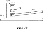
検知システムをまとめて整列させる別の機構が図10に示されている。図5の受け台62がハウジング60に対し立面状態で略示されている。多数の配置部を有するブラケット110によって、前記受け台の一端をハウジング60の内面に対する種々の位置の一つに位置せしめることができるようになっている。リーフスプリングのような弾性部材112を前記ブラケットの各配置位置に設けて、そこに配置位置された前記部材の動きを抑えるようにすることが好ましい。複数のソケット又は溝に嵌まる複数のタブ又はキーのようなフィジカルな特徴部を設けてブラケット110に取り付けた前記部材を積極的に係合させることもできる。
【0026】
かくして受け台62に取り付けた回路板66の対向端部に配置の能動要素の視界は、受け台62をブラケットにおける一つの配置位置から別の配置位置へ移すことで調節される。この場合、ハウジング60から受け台62の底部に向け突出する複数の柱64は、ハウジング60の主となる面に平行の受け台62の横方向の動きに主として抵抗するようになっている。
【0027】
別の実施の態様においては、回路板66は、変形の受け台62に係合し、受け台それ自体は、図10に示すように、多数の配置部を有するブラケット110を支持する。さらにまた、受け台62が無いときは、図1に示すように、回路板20をハウジング40に取り付けたブラケット110における複数の配置位置の一つに配置できる。別の実施の態様では、図1に示すように複数のセクションに分けた回路板20の一つ又は複数のサブセクションに前記のようなブラケッテオ110を使用できる。さらにブラケット110は、独立したユニットとして図示されているが、自動車のトリム部材の面に設けた互いに平行な多数のリブとして設けることができる。
【0028】
図10の多数の配置部を有するブラケット110による機動性と受け台62、受け台62に取り付けられる回路板66又は独立した回路板44,46、図1に示すような回路板アッセンブリー20に使用できるようになっている適合力にも拘らず、障害物検知システムの能動要素の視界をさらによくすることが度々必要になる。この目的のために、ここに記載の発明の図11に示した一つの実施の態様においては、ハウジングに対し回路板120の向きを立体的にこまやかに調整できるようにする。
【0029】
図11の回路板120は、図1の部分部分に分けられた回路板20、図3の一体の回路板44,46のいずれか又は図6の受け台に取り付けた回路板66を現す。さらに、図5の受け台62を同様にしてハウジング60に取り付けることができる。いずれの場合でも、回路板120は、取り付け面122から出ている突起124に当接する。取り付け面122は、ハウジング40(図3)、ハウジング60(図5)又は受け台62(図5)を現す。図示のように、突起124は、半球体であるが、回路板120又は的を定める他の面が接触するピボットポイントになる形状のものに代えることができる。さらに、突起124は、取り付け面122に設けられていることが好ましいが、回路板120に形成し、取り付け面122に接触するように突き出ているものでもよい。
【0030】
回路板120は、ねじのような少なくとも3本の高さ寸法が調節できるファスナー126を使用して、下側の取り付け面122に機械的に接続される。ファスナー126のまわりに設けたスプリングのような弾性要素128を回路板120と取り付け面122との中間に介在させて、取り付け面122に対する所望の位置に回路板120を維持するようになっている。一つ又は複数のファスナー126の高さ寸法を調節することで、回路板120の傾斜角度を変えることができる。ファスナー126のねじ溝のピッチに応じて、前記ハウジングに対する回路板の向きを極めてこまやかに調節することができる。
【0031】
図示し、上記した発明のこれらの実施の態様およびその他の実施の態様は、あくまでも例示であって、この発明の真の範囲は、上述の範囲と真髄によってのみ制限されるものである。
【図面の簡単な説明】
ここに記載の発明のこれら及び他の目的は、以下の図面を参照することでより完全に理解される:
【図1】ここに記載の発明による障害物検知システムの構成部品類の説明図。
【図2】ここに記載の発明による障害物検知システムのハウジングの第1の実施の態様の外面斜視図。
【図3】図2のハウジングの内面斜視図。
【図4】自動車のドアの金属板に、ここに記載の発明の障害物検知システムを配置した状態の図。
【図5】図1の障害物検知システムの別の実施の態様の構成部品類の説明図。
【図6】図5の障害物検知システムの実施の態様に使用の回路板の平面図。
【図7】図5の障害物検知システムの実施の態様に使用のレンズモジュールの平面図。
【図8】ここに記載の障害物検知システムのためのファスナーの断面図。
【図9】図8のファスナーを受ける孔の平面図。
【図10】ここに記載の障害物検知システムに使用される第1の整列機構の立面図。
【図11】ここに記載の障害物検知システムに使用される第2の整列機構の立面図。[0001]
Cross-reference of consecutive applications
This application claims priority to US Provisional Patent Application No. 60 / 257,081, filed December 20, 2000, which is incorporated herein by reference.
[0003]
Description of federal aid research or development
BACKGROUND OF THE INVENTION
The present invention relates to an electronic sensor system that monitors a window, a door, or other opening related to an automobile or an interior of the automobile, and in particular, is equipped with a sensor system or the like, has a target, and / or It relates to the built-in system.
[0006]
In recent years, the use of electronic sensors for detecting obstacles or detecting intrusions in the window mechanism of automobiles has not been performed due to limitations in terms of complexity and wearing. Generally speaking, obstacle detection is based on limit switches, window motor characteristics or ultrasonic monitor signals, which meet the requirements for accurate mounting and alignment. Not. Small variations in the installed sensing system do not significantly affect the performance of these sensor systems. If there are a wide variety of mounting adjustment members and wearer's technology, the function will be reduced as a result of a faulty mounting state that does not match the ideal mounting form, and therefore, it is highly sensitive, so accuracy However, there is no need to use a good monitoring system.
[0007]
Lens-to-obstacle detection system emitter or detector, emitter or detector pair mounted circuit board, housing of each circuit board pair, housing to automobile trim member and / or door panel, and automobile Variations in the physical relationship between the trim member and / or door panel-to-door metal plate material can be offset by various so-called tolerances. Changes in vehicle types and door changes in system installation technology in automobile factories and system installation technology by post-sales installation engineers all increase the problem of allowable errors.
[0008]
DETAILED DESCRIPTION OF THE INVENTION
The invention described herein accurately installs an obstacle detection system, such as for use in connection with an automobile window, and further aligns the components of the system for maximum functionality. It is something that can be done. The obstacle detection system according to the invention described herein comprises an active circuit responsive to the detection of an obstacle and a mounting subsystem capable of accurately aligning and arranging portions of the active circuit.
[0010]
FIG. 1 is an explanatory diagram of a circuit board used as a part of the active circuitry. Individual active components and their operation are owned by the same assignee as this application and are described in US Pat. No. 5,955,854, incorporated herein by reference. Referring to FIG. 1, an energy field is generated by the use of infrared (IR) light emitting diodes (LEDs) 12 near the window opening through which the power window moves. The energy reflected by one or more obstacles or surfaces in the radiation path of the emitted energy is detected by a plurality of IR detectors 14 arranged together. A
[0011]
The entire circuit configuration is mounted using one or a plurality of
[0012]
A portion of the system described herein that is used to mount an obstacle detection system in an automobile includes a
[0013]
One or
[0014]
FIG. 3 is a perspective view of the opposite side of the
[0015]
FIG. 5, similar to FIG. 3, shows the back side of the housing used for mounting near the opening to monitor the obstacle detection circuitry. However, in this case, the
[0016]
One form of circuit board that is most suitable for mounting on the
[0017]
The embodiment of FIGS. 1 and 3 is suitable for many applications, but otherwise, stacking is acceptable by moving the
[0018]
Allowable stacking due to misalignment between the lens and the emitter or detector, which is also to deal with the so-called boresight error (boresight error), in order to cope with the effect of said lens and each of the lenses. It is preferable to eliminate the distance between the emitters or the sensing elements and to eliminate arbitrary movement between them. According to one aspect of the invention described herein, the above point is addressed by providing an
[0019]
Electrical leads 82 communicating with the respective emitters or detectors extend from the rear surface of the
[0020]
In spite of the reduced stacking allowed by the
[0021]
Due to the round cross-section of the usual Christmas tree trunk, these fasteners may rotate freely after installation or move in a different manner. To address this shortcoming, the system described herein uses at least one and preferably several modified
[0022]
In the prior art, the holes that receive the usual Christmas tree fasteners were circular, but in the system described here, they are formed on the
[0023]
In one embodiment, the
[0024]
Even if the modified
[0025]
Another mechanism for aligning the sensing systems together is shown in FIG. The
[0026]
Thus, the field of view of the active elements located at the opposite ends of the
[0027]
In another embodiment, the
[0028]
The mobility by the
[0029]
The
[0030]
The
[0031]
These and other embodiments of the invention shown and described above are exemplary only, and the true scope of the invention is limited only by the scope and essence described above.
[Brief description of the drawings]
These and other objects of the invention described herein will be more fully understood with reference to the following drawings:
FIG. 1 is an explanatory diagram of components of an obstacle detection system according to the invention described herein.
FIG. 2 is an external perspective view of a first embodiment of a housing of an obstacle detection system according to the invention described herein.
3 is an internal perspective view of the housing of FIG. 2. FIG.
FIG. 4 is a diagram showing a state in which the obstacle detection system according to the invention described herein is arranged on a metal plate of a door of an automobile.
FIG. 5 is an explanatory diagram of components of another embodiment of the obstacle detection system of FIG. 1;
6 is a plan view of a circuit board used in the embodiment of the obstacle detection system of FIG. 5. FIG.
7 is a plan view of a lens module used in the embodiment of the obstacle detection system of FIG. 5. FIG.
FIG. 8 is a cross-sectional view of a fastener for the obstacle detection system described herein.
9 is a plan view of a hole that receives the fastener of FIG. 8. FIG.
FIG. 10 is an elevation view of a first alignment mechanism used in the obstacle detection system described herein.
FIG. 11 is an elevation view of a second alignment mechanism used in the obstacle detection system described herein.
Claims (21)
以下を備えるモニタ・サブシステム
ハウジング、
前記ハウジングに関連して配置された少なくとも一つの回路板、
前記少なくとも一つの回路板に配置されていて、エネルギー・フィールドを発生するエミッタ要素、
前記少なくとも一つの回路板に配置されていて、前記エネルギー・フィールドの少なくとも一部を受ける検知器(ディテクタ)要素及び
前記エネルギー・フィールドを再指向させる少なくとも一つのレンズ;及び
以下を備える取り付けサブシステム
少なくとも一つの配置部材、
前記少なくとも一つの回路板を第1の精度度合いに位置決めすることを可能にする大まかな調節機構、及び
前記少なくとも一つの回路板を第2の精度度合いに位置決めすることを可能にする微調節機構、
及び
前記第2の精度度合いが前記第1の精度度合いよりも精度がよくなっていること。Obstacle detection system comprising:
A monitor subsystem housing comprising:
At least one circuit board disposed in relation to the housing;
An emitter element disposed on the at least one circuit board for generating an energy field;
A mounting subsystem comprising at least one lens disposed on the at least one circuit board and receiving at least a portion of the energy field; and at least one lens redirecting the energy field; and One arrangement member,
A rough adjustment mechanism that allows the at least one circuit board to be positioned with a first degree of accuracy, and a fine adjustment mechanism that allows the at least one circuit board to be positioned with a second degree of accuracy;
And the second accuracy level is better than the first accuracy level.
Applications Claiming Priority (2)
| Application Number | Priority Date | Filing Date | Title |
|---|---|---|---|
| US25708100P | 2000-12-20 | 2000-12-20 | |
| PCT/US2001/049724 WO2002050553A2 (en) | 2000-12-20 | 2001-12-20 | Sensor mounting system |
Publications (1)
| Publication Number | Publication Date |
|---|---|
| JP2005528290A true JP2005528290A (en) | 2005-09-22 |
Family
ID=22974792
Family Applications (1)
| Application Number | Title | Priority Date | Filing Date |
|---|---|---|---|
| JP2004567198A Pending JP2005528290A (en) | 2000-12-20 | 2001-12-20 | Sensor mounting system |
Country Status (6)
| Country | Link |
|---|---|
| US (1) | US6720884B2 (en) |
| EP (1) | EP1346331A4 (en) |
| JP (1) | JP2005528290A (en) |
| CA (1) | CA2432307A1 (en) |
| MX (1) | MXPA03005480A (en) |
| WO (1) | WO2002050553A2 (en) |
Families Citing this family (11)
| Publication number | Priority date | Publication date | Assignee | Title |
|---|---|---|---|---|
| US7415891B2 (en) * | 2005-09-30 | 2008-08-26 | Rockwell Automation Technologies, Inc. | Sensor mounting structure with snapping feature |
| US7527437B2 (en) * | 2005-09-30 | 2009-05-05 | Rockwell Automation Technologies, Inc. | Sensor mounting structure with light pipe |
| US7546780B2 (en) * | 2005-09-30 | 2009-06-16 | Rockwell Automation Technologies, Inc. | Sensor mounting structure allowing for adjustment of sensor position |
| US7412900B2 (en) * | 2005-09-30 | 2008-08-19 | Rockwell Automation Technologies, Inc. | Sensor mounting structure with adjustable swivel ball and panel mounting mechanism |
| US8439425B2 (en) | 2010-04-21 | 2013-05-14 | Honda Motor Co., Ltd. | Sensor housing |
| CN104379410B (en) * | 2012-06-26 | 2016-12-28 | 翰昂系统有限公司 | Temperature survey in vehicle chamber infrared ray sensor assembly |
| KR101459910B1 (en) * | 2013-05-28 | 2014-11-07 | 현대자동차주식회사 | Radar apparatus for vehicle |
| US9956993B1 (en) | 2017-01-20 | 2018-05-01 | Ford Global Technologies, Llc | Vehicle front impact sensor with impact resistant carriage |
| US10519642B2 (en) | 2017-04-26 | 2019-12-31 | Masco Canada Limited | Adjustable sensor device for a plumbing fixture |
| CN111142120B (en) * | 2020-02-25 | 2025-12-09 | 珠海一微科技股份有限公司 | Infrared receiving and transmitting unit, detection device, multi-infrared detection device and obstacle avoidance robot |
| CA3141724A1 (en) | 2020-12-30 | 2022-06-30 | Op-Hygiene Ip Gmbh | Smart module with adjustable time of flight sensor |
Family Cites Families (22)
| Publication number | Priority date | Publication date | Assignee | Title |
|---|---|---|---|---|
| US4505054A (en) | 1983-05-25 | 1985-03-19 | Prince Corporation | Magnetic sensor mounting system |
| US5153419A (en) | 1985-04-22 | 1992-10-06 | Canon Kabushiki Kaisha | Device for detecting position of a light source with source position adjusting means |
| US4687924A (en) * | 1985-05-08 | 1987-08-18 | Adt Inc. | Modular transceiver with adjustable specular member |
| JPS63268130A (en) * | 1987-04-24 | 1988-11-04 | Mitsubishi Electric Corp | Photodetector position adjustment device |
| JPH03203029A (en) * | 1989-12-28 | 1991-09-04 | Pioneer Electron Corp | Information reader |
| US5103917A (en) * | 1990-04-27 | 1992-04-14 | Sukup Manufacturing Company | Adjustable calibration assembly for a guidance system |
| US5210406A (en) | 1991-06-10 | 1993-05-11 | Beran Mark A | Presence detector housing and mount |
| US5219068A (en) * | 1991-07-16 | 1993-06-15 | Cincinnati Milacron, Inc. | Adjustable proximity switch mounting assembly |
| IT223271Z2 (en) * | 1991-07-31 | 1995-06-21 | Fiat Ricerche | FANTASY GROUP FOR VEHICLES INCORPORATING AN OBSTACLE RELIEF SYSTEM. |
| FI914598A7 (en) | 1991-09-30 | 1993-03-31 | Valtion Teknillinen | FOERFARANDE I EN MED OPTISK PRINCIP FUNGERANDE ANKOMSTKOPPLING |
| US5191222A (en) * | 1991-10-23 | 1993-03-02 | Pitney Bowes Inc. | Apparatus for synchronizing data reading capabilities of an optical reader |
| US5235574A (en) * | 1991-11-04 | 1993-08-10 | International Business Machines Corporation | Optical disk drive relative position sensor |
| US5457314A (en) * | 1991-12-31 | 1995-10-10 | Hyundai Electronics Industries Co., Ltd. | Mount for positioning a photodetector on an optical apparatus |
| DE69222160T2 (en) * | 1992-06-29 | 1998-02-19 | Oce Tech Bv | Mounting structure for electro-optical devices |
| US5955854A (en) * | 1992-09-29 | 1999-09-21 | Prospects Corporation | Power driven venting of a vehicle |
| FI98766C (en) | 1994-01-11 | 1997-08-11 | Vaisala Oy | Device and method for measuring visibility and prevailing weather conditions |
| AU683152B2 (en) * | 1994-05-31 | 1997-10-30 | Hochiki Kabushiki Kaisha | Projected beam-type smoke detector |
| JP3095971B2 (en) | 1995-02-07 | 2000-10-10 | 本田技研工業株式会社 | Headlight device for vehicles |
| US5757004A (en) * | 1995-08-11 | 1998-05-26 | Larry C. Y. Lee | Motion detector with external range adjustment |
| US5938320A (en) * | 1997-03-19 | 1999-08-17 | Harman Automotive, Inc. | Enhanced illuminated polymeric indicator employed in a mirror housing of an automotive vehicle |
| DE19833065B4 (en) | 1997-07-22 | 2010-04-15 | DENSO CORPORATION, Kariya-shi | An angular displacement determining device for determining the angular displacement of the radar center axis for use in a self-locating obstacle detection system |
| US6479823B1 (en) * | 1999-08-11 | 2002-11-12 | Hubbell Incorporated | Apparatus and method for lens adjustment |
-
2001
- 2001-12-20 JP JP2004567198A patent/JP2005528290A/en active Pending
- 2001-12-20 MX MXPA03005480A patent/MXPA03005480A/en unknown
- 2001-12-20 CA CA002432307A patent/CA2432307A1/en not_active Abandoned
- 2001-12-20 EP EP01992252A patent/EP1346331A4/en not_active Withdrawn
- 2001-12-20 WO PCT/US2001/049724 patent/WO2002050553A2/en not_active Ceased
- 2001-12-20 US US10/029,062 patent/US6720884B2/en not_active Expired - Fee Related
Also Published As
| Publication number | Publication date |
|---|---|
| WO2002050553A3 (en) | 2002-09-12 |
| US6720884B2 (en) | 2004-04-13 |
| EP1346331A2 (en) | 2003-09-24 |
| US20020101694A1 (en) | 2002-08-01 |
| MXPA03005480A (en) | 2003-09-25 |
| CA2432307A1 (en) | 2002-06-27 |
| WO2002050553A8 (en) | 2003-03-06 |
| WO2002050553A9 (en) | 2003-08-14 |
| EP1346331A4 (en) | 2004-07-14 |
| WO2002050553A2 (en) | 2002-06-27 |
Similar Documents
| Publication | Publication Date | Title |
|---|---|---|
| US12379209B2 (en) | Electronic device having a vision system assembly held by a self-aligning bracket assembly | |
| JP7597850B2 (en) | Portable Electronic Devices | |
| JP2005528290A (en) | Sensor mounting system | |
| US7348536B2 (en) | Light grid with housing | |
| EP3096070B1 (en) | Light emission module, connector, and mounting structure for light emission module | |
| JP4995438B2 (en) | Reflective photoelectric switch | |
| US7546766B2 (en) | Sun sensor using MID technology | |
| JP2632625B2 (en) | Sensor module | |
| JP6858013B2 (en) | Assembly structure and bracket | |
| JP5842222B2 (en) | Decorative cover and mounting structure for security sensor device | |
| JPH0740229Y2 (en) | Reflective photoelectric switch | |
| JPH0669777U (en) | Indoor mounted detector |