JP2005518238A - Cepstrum region pulse oximeter - Google Patents
Cepstrum region pulse oximeter Download PDFInfo
- Publication number
- JP2005518238A JP2005518238A JP2003570692A JP2003570692A JP2005518238A JP 2005518238 A JP2005518238 A JP 2005518238A JP 2003570692 A JP2003570692 A JP 2003570692A JP 2003570692 A JP2003570692 A JP 2003570692A JP 2005518238 A JP2005518238 A JP 2005518238A
- Authority
- JP
- Japan
- Prior art keywords
- signal
- patient
- domain
- cepstrum
- time domain
- Prior art date
- Legal status (The legal status is an assumption and is not a legal conclusion. Google has not performed a legal analysis and makes no representation as to the accuracy of the status listed.)
- Pending
Links
- 238000000034 method Methods 0.000 claims abstract description 76
- 238000001228 spectrum Methods 0.000 claims abstract description 69
- 229910003798 SPO2 Inorganic materials 0.000 claims abstract description 26
- 101100478210 Schizosaccharomyces pombe (strain 972 / ATCC 24843) spo2 gene Proteins 0.000 claims abstract description 26
- 238000009499 grossing Methods 0.000 claims abstract description 19
- 238000012545 processing Methods 0.000 claims abstract description 14
- 230000004962 physiological condition Effects 0.000 claims abstract 4
- 230000003595 spectral effect Effects 0.000 claims description 85
- 230000033001 locomotion Effects 0.000 claims description 42
- 230000003287 optical effect Effects 0.000 claims description 38
- 230000000875 corresponding effect Effects 0.000 claims description 32
- 238000004159 blood analysis Methods 0.000 claims description 12
- 238000005070 sampling Methods 0.000 claims description 12
- 230000002238 attenuated effect Effects 0.000 claims description 11
- 230000035790 physiological processes and functions Effects 0.000 claims description 9
- 230000003044 adaptive effect Effects 0.000 claims description 7
- 238000001914 filtration Methods 0.000 claims description 7
- 230000002596 correlated effect Effects 0.000 claims description 3
- 238000003672 processing method Methods 0.000 abstract description 14
- 230000008569 process Effects 0.000 description 10
- 238000010586 diagram Methods 0.000 description 6
- 239000000523 sample Substances 0.000 description 6
- 238000000611 regression analysis Methods 0.000 description 3
- 238000004458 analytical method Methods 0.000 description 2
- 239000008280 blood Substances 0.000 description 2
- 210000004369 blood Anatomy 0.000 description 2
- 238000006243 chemical reaction Methods 0.000 description 2
- 230000004044 response Effects 0.000 description 2
- 230000006978 adaptation Effects 0.000 description 1
- 230000002411 adverse Effects 0.000 description 1
- 238000013459 approach Methods 0.000 description 1
- 238000013528 artificial neural network Methods 0.000 description 1
- QVGXLLKOCUKJST-UHFFFAOYSA-N atomic oxygen Chemical compound [O] QVGXLLKOCUKJST-UHFFFAOYSA-N 0.000 description 1
- 230000005540 biological transmission Effects 0.000 description 1
- 238000004364 calculation method Methods 0.000 description 1
- 239000002131 composite material Substances 0.000 description 1
- 238000007796 conventional method Methods 0.000 description 1
- 210000000624 ear auricle Anatomy 0.000 description 1
- 230000002708 enhancing effect Effects 0.000 description 1
- 230000007274 generation of a signal involved in cell-cell signaling Effects 0.000 description 1
- 238000009532 heart rate measurement Methods 0.000 description 1
- 238000002329 infrared spectrum Methods 0.000 description 1
- 238000005259 measurement Methods 0.000 description 1
- 238000012986 modification Methods 0.000 description 1
- 230000004048 modification Effects 0.000 description 1
- 239000013307 optical fiber Substances 0.000 description 1
- 229910052760 oxygen Inorganic materials 0.000 description 1
- 239000001301 oxygen Substances 0.000 description 1
- 238000002106 pulse oximetry Methods 0.000 description 1
- 230000011218 segmentation Effects 0.000 description 1
- 230000009466 transformation Effects 0.000 description 1
Images


Classifications
-
- A—HUMAN NECESSITIES
- A61—MEDICAL OR VETERINARY SCIENCE; HYGIENE
- A61B—DIAGNOSIS; SURGERY; IDENTIFICATION
- A61B5/00—Measuring for diagnostic purposes; Identification of persons
- A61B5/145—Measuring characteristics of blood in vivo, e.g. gas concentration or pH-value ; Measuring characteristics of body fluids or tissues, e.g. interstitial fluid or cerebral tissue
- A61B5/1455—Measuring characteristics of blood in vivo, e.g. gas concentration or pH-value ; Measuring characteristics of body fluids or tissues, e.g. interstitial fluid or cerebral tissue using optical sensors, e.g. spectral photometrical oximeters
- A61B5/14551—Measuring characteristics of blood in vivo, e.g. gas concentration or pH-value ; Measuring characteristics of body fluids or tissues, e.g. interstitial fluid or cerebral tissue using optical sensors, e.g. spectral photometrical oximeters for measuring blood gases
-
- A—HUMAN NECESSITIES
- A61—MEDICAL OR VETERINARY SCIENCE; HYGIENE
- A61B—DIAGNOSIS; SURGERY; IDENTIFICATION
- A61B5/00—Measuring for diagnostic purposes; Identification of persons
- A61B5/02—Detecting, measuring or recording for evaluating the cardiovascular system, e.g. pulse, heart rate, blood pressure or blood flow
- A61B5/024—Measuring pulse rate or heart rate
- A61B5/02416—Measuring pulse rate or heart rate using photoplethysmograph signals, e.g. generated by infrared radiation
-
- A—HUMAN NECESSITIES
- A61—MEDICAL OR VETERINARY SCIENCE; HYGIENE
- A61B—DIAGNOSIS; SURGERY; IDENTIFICATION
- A61B5/00—Measuring for diagnostic purposes; Identification of persons
- A61B5/72—Signal processing specially adapted for physiological signals or for diagnostic purposes
- A61B5/7235—Details of waveform analysis
- A61B5/7253—Details of waveform analysis characterised by using transforms
- A61B5/7257—Details of waveform analysis characterised by using transforms using Fourier transforms
-
- A—HUMAN NECESSITIES
- A61—MEDICAL OR VETERINARY SCIENCE; HYGIENE
- A61B—DIAGNOSIS; SURGERY; IDENTIFICATION
- A61B5/00—Measuring for diagnostic purposes; Identification of persons
- A61B5/72—Signal processing specially adapted for physiological signals or for diagnostic purposes
- A61B5/7203—Signal processing specially adapted for physiological signals or for diagnostic purposes for noise prevention, reduction or removal
- A61B5/7207—Signal processing specially adapted for physiological signals or for diagnostic purposes for noise prevention, reduction or removal of noise induced by motion artifacts
Landscapes
- Health & Medical Sciences (AREA)
- Life Sciences & Earth Sciences (AREA)
- Physics & Mathematics (AREA)
- Engineering & Computer Science (AREA)
- Surgery (AREA)
- Public Health (AREA)
- Pathology (AREA)
- Veterinary Medicine (AREA)
- Biomedical Technology (AREA)
- Heart & Thoracic Surgery (AREA)
- Medical Informatics (AREA)
- Molecular Biology (AREA)
- Biophysics (AREA)
- Animal Behavior & Ethology (AREA)
- General Health & Medical Sciences (AREA)
- Cardiology (AREA)
- Physiology (AREA)
- Spectroscopy & Molecular Physics (AREA)
- Optics & Photonics (AREA)
- Mathematical Physics (AREA)
- Artificial Intelligence (AREA)
- Computer Vision & Pattern Recognition (AREA)
- Psychiatry (AREA)
- Signal Processing (AREA)
- Measurement Of The Respiration, Hearing Ability, Form, And Blood Characteristics Of Living Organisms (AREA)
- Measuring Pulse, Heart Rate, Blood Pressure Or Blood Flow (AREA)
Abstract
プレチスモグラフ信号をケプストラム領域で処理する方法を提供する。一実施形態では、ケプストラム領域プレチスモグラフ信号処理方法(200)は、時間領域プレチスモグラフ信号を取得する工程(210)、時間領域プレチスモグラフ信号を平滑化する工程(220)、時間領域プレチスモグラフ信号に対して第1段階フーリェ変換を行なって時間領域プレチスモグラフ信号を周波数領域プレチスモグラフ信号に変換する工程(230)、パワースペクトルを周波数領域プレチスモグラフ信号から算出する工程(240)、パワースペクトルを対数関数でスケーリングする工程(250)、対数変換されたスペクトルに対して第2段階フーリェ変換を行なってパワースペクトルをケプストラムに変換する工程(260)、ケプストラムを検討してこれらのケプストラムから患者の脈拍数またはSPO2レベルのような患者の生理状態に関する情報を取得する工程(270)、を含む。A method for processing a plethysmograph signal in a cepstrum domain is provided. In one embodiment, the cepstrum domain plethysmograph signal processing method (200) includes obtaining a time domain plethysmograph signal (210), smoothing the time domain plethysmograph signal (220), and first to the time domain plethysmograph signal. Performing step Fourier transform to convert a time-domain plethysmograph signal into a frequency-domain plethysmograph signal (230); calculating a power spectrum from the frequency-domain plethysmograph signal (240); scaling the power spectrum with a logarithmic function (250) Performing a second-stage Fourier transform on the logarithmically transformed spectrum to convert the power spectrum into cepstrum (260); reviewing the cepstrum from the cepstrum to the patient's pulse rate or SPO2 level; Step (270) to obtain information about physiological condition of the patient, such as, including.
Description
(関連出願の相互参照)
本出願は、「ケプストラム領域パルスオキシメータ」と題する2002年2月22日出願の米国仮出願シリーズ番号60/359,018の優先権を主張するものであり、この出願の全ての開示内容が本明細書に援用される。
(Cross-reference of related applications)
This application claims priority from US Provisional Application Series No. 60 / 359,018, filed February 22, 2002, entitled “Cepstrum Domain Pulse Oximeter”, the entire disclosure of which is incorporated herein by reference. Incorporated herein by reference.
本発明はパルスオキシメータ(パルス酸素濃度計)に関し、特にプレチスモグラフ信号のケプストラム領域処理を用いる脈拍数及び血液分析レベル推定に関する。 The present invention relates to pulse oximeters, and more particularly to pulse rate and blood analysis level estimation using cepstrum region processing of plethysmographic signals.
現在のパルスオキシメータでは、赤色光信号及び赤外光信号が患者の組織部位、通常指を通過するときに、これらの信号の減衰により生じる2つの信号が得られる。当業界においては、減衰赤色光信号及び赤外光信号から脈拍数情報及び動脈血液の酸素濃度(SpO2)レベルの双方を得るために、時間領域及び周波数領域の双方において多くの処理方法が開発されてきた。減衰赤色光信号及び赤外光信号は患者の心拍数に関連するパルス波形を示す。これらの時間領域信号は、通常幾つかの帯域フィルタリング処理を施された後に、脈拍周期の表示に使用され、プレチスモグラフ信号として知られる。従来の脈拍数推定技術は、ほとんどの場合、時間領域で処理されて、ピークピッキング及びピーク解析を使用して脈拍数を決定していた。時間領域指標は脈拍数変化に高速に応答するが、ゆっくりとした動きの、かつ/または小さい振幅の脈波が在ると、正確なピークピッキングに問題が生じる。周波数領域またはスペクトル領域での処理も使用されてきたが、この処理には脈拍推定値を生成するために波形の長いサンプルが必要となる。また、脈波により生じる主たるスペクトルピークを特定する操作では、モーションアーチファクトが在ると問題が生じる。 In current pulse oximeters, when a red light signal and an infrared light signal pass through a patient's tissue site, usually a finger, two signals resulting from the attenuation of these signals are obtained. In the industry, many processing methods have been developed in both time and frequency domains to obtain both pulse rate information and arterial blood oxygen concentration (SpO2) levels from attenuated red and infrared light signals. I came. The attenuated red light signal and the infrared light signal show pulse waveforms related to the patient's heart rate. These time domain signals are usually used for the display of the pulse period after some band filtering and are known as plethysmographic signals. Conventional pulse rate estimation techniques are most often processed in the time domain to determine the pulse rate using peak picking and peak analysis. Time domain indicators respond quickly to pulse rate changes, but slow peaking and / or small amplitude pulse waves can cause problems with accurate peak picking. Frequency or spectral domain processing has also been used, but this process requires long samples of the waveform to generate a pulse estimate. Further, in the operation of specifying the main spectrum peak generated by the pulse wave, there is a problem if there is a motion artifact.
従って本発明は、特にモーションアーチファクトがプレチスモグラフ信号に含まれる場合に、プレチスモグラフ信号をケプストラム領域で処理して、患者の脈拍数及びSPO2レベル情報のような患者の生理状態関連情報をプレチスモグラフ信号から決定することを改善する。 Accordingly, the present invention processes the plethysmographic signal in the cepstrum domain, particularly when motion artifacts are included in the plethysmographic signal, to determine patient physiological state related information such as patient pulse rate and SPO2 level information from the plethysmographic signal. To improve.
本発明によれば、プレチスモグラフ信号(例えば、減衰赤色信号及び減衰赤外信号)をサンプリングし、例えば2つの順フーリェ変換の間に挟まれた対数尤度変換(logarithmic like transform)を通じて、ケプストラム領域に変換する。ケプストラム領域のピーク群は主として脈拍数に関連する。脈拍によって生じるケプストラム領域ピークを特定することにより中程度のモーションアーチファクトの存在下でのパルス推定が可能になる。ケプストラム情報はまた、入力プレチスモグラフ信号に対する適応フィルタリングが、ノイズ及びアーチファクトを取り除くことを可能にする。赤色光信号及び赤外光信号の双方のケプストラムピークの相対振幅は、赤色信号及び赤外信号のDCレベルの推定値と協働して、血液の血液分析(例えばSPO2)レベルの測定も可能にする。 According to the present invention, a plethysmograph signal (eg, attenuated red signal and attenuated infrared signal) is sampled and, for example, into a cepstrum domain through a logarithmic likelihood transform sandwiched between two forward Fourier transforms. Convert. The peak group in the cepstrum region is mainly related to the pulse rate. Identifying the cepstrum region peaks caused by the pulse enables pulse estimation in the presence of moderate motion artifacts. The cepstrum information also allows adaptive filtering on the input plethysmograph signal to remove noise and artifacts. The relative amplitudes of the cepstrum peaks of both the red and infrared light signals, in conjunction with an estimate of the DC level of the red and infrared signals, also allows measurement of blood analysis (eg SPO2) levels of blood. To do.
本発明の一態様によれば、患者から得られる少なくとも第1及び第2の時間領域プレチスモグラフ信号(例えば、赤色プレチスモグラフ信号及び赤外プレチスモグラフ信号)を処理する方法は、第1の時間領域プレチスモグラフ信号に対してフーリェ変換を行なって
第1のプレチスモグラフ信号を第1の周波数領域プレチスモグラフ信号に変換する工程と、第2の時間領域プレチスモグラフ信号に対してフーリェ変換を行なって第2のプレチスモグラフ信号を第2の周波数領域プレチスモグラフ信号に変換する工程とを備える。この点に関して、フーリェ変換は高速フーリェ変換とすることができる。第1パワースペクトルは第1の周波数領域プレチスモグラフ信号から算出され、第2パワースペクトルは第2の周波数領域プレチスモグラフ信号から算出される。フーリェ変換を第1パワースペクトルに対して行なって、第1パワースペクトルを第1ケプストラムに変換し、かつフーリェ変換を第2パワースペクトルに対して行なって、第2パワースペクトルを第2ケプストラムに変換する。この点に関して、フーリェ変換は高速フーリェ変換とすることができる。次に、第1及び第2ケプストラムを検討して患者の生理状態に関する情報をこれらのケプストラムから取得する。
According to one aspect of the present invention, a method for processing at least first and second time domain plethysmographic signals (eg, red plethysmographic signal and infrared plethysmographic signal) obtained from a patient is provided on the first time domain plethysmographic signal. Performing a Fourier transform on the first to convert the first plethysmograph signal into a first frequency domain plethysmograph signal; and performing a Fourier transform on the second time domain plethysmograph signal to convert the second plethysmograph signal into a second Converting to a frequency domain plethysmograph signal. In this regard, the Fourier transform can be a fast Fourier transform. The first power spectrum is calculated from the first frequency domain plethysmograph signal, and the second power spectrum is calculated from the second frequency domain plethysmograph signal. A Fourier transform is performed on the first power spectrum to convert the first power spectrum to the first cepstrum, and a Fourier transform is performed on the second power spectrum to convert the second power spectrum to the second cepstrum. . In this regard, the Fourier transform can be a fast Fourier transform. Next, the first and second cepstrum are examined to obtain information about the physiological state of the patient from these cepstrum.
患者の生理状態は、例えば患者の脈拍数とすることができる。この点に関して、第1及び第2ケプストラムを検討して患者の脈拍数に関連する第1及び第2ケプストラムのピークを特定し、患者の脈拍数を第1及び第2ケプストラムの特定したピークの位置に基づいて推定することができる。 The physiological state of the patient can be, for example, the patient's pulse rate. In this regard, the first and second cepstrum are examined to identify the first and second cepstrum peaks associated with the patient's pulse rate, and the patient's pulse rate is determined to be the position of the identified peak of the first and second cepstrum. Can be estimated.
患者の生理状態は、例えば患者のSPO2レベルとすることもできる。この点に関して、第1及び第2パワースペクトルのDCレベルを決定し、第1及び第2の時間領域プレチスモグラフ信号のACレベルを第1及び第2ケプストラムの特定したピークから決定し、第1及び第2パワースペクトルのDC値及び第1及び第2の時間領域プレチスモグラフ信号のACレベルから患者の血液分析レベル(例えばSPO2レベル)と相互に関連する値を算出することができる。 The patient's physiological state may be, for example, the patient's SPO2 level. In this regard, the DC levels of the first and second power spectra are determined, the AC levels of the first and second time domain plethysmographic signals are determined from the identified peaks of the first and second cepstrum, and the first and second A value correlated with the patient's blood analysis level (eg, SPO2 level) can be calculated from the DC value of the two power spectrum and the AC level of the first and second time domain plethysmographic signals.
本発明の別の態様によれば、患者の脈拍数を、患者から得られる少なくとも一つの時間領域プレチスモグラフ信号から決定する方法は、患者の脈拍数の時間領域ベースの推定値を時間領域プレチスモグラフ信号から取得する工程を含む。時間領域プレチスモグラフ信号はスペクトル領域プレチスモグラフ信号に変換され、患者の脈拍数のスペクトル領域ベースの推定値はスペクトル領域プレチスモグラフ信号から取得される。スペクトル領域プレチスモグラフ信号はケプストラム領域プレチスモグラフ信号に変換され、患者の脈拍数のケプストラム領域ベースの推定値はケプストラム領域プレチスモグラフ信号から取得される。次に患者の脈拍数の最良の推定値は、少なくとも患者の脈拍数の時間領域ベースの推定値、スペクトル領域ベースの推定値及びケプストラム領域ベースの推定値に基づいて決定しられる。 In accordance with another aspect of the present invention, a method for determining a patient's pulse rate from at least one time domain plethysmographic signal obtained from a patient comprises obtaining a time domain based estimate of the patient's pulse rate from the time domain plethysmographic signal. Including the step of obtaining. The time domain plethysmographic signal is converted to a spectral domain plethysmographic signal, and a spectral domain based estimate of the patient's pulse rate is obtained from the spectral domain plethysmographic signal. The spectral domain plethysmograph signal is converted to a cepstrum domain plethysmograph signal, and a cepstrum domain based estimate of the patient's pulse rate is obtained from the cepstrum domain plethysmograph signal. The best estimate of the patient's pulse rate is then determined based on at least a time domain based estimate, a spectral domain based estimate and a cepstrum domain based estimate of the patient's pulse rate.
本発明の別の態様によれば、パルスオキシメータは、第1及び第2波長(例えば、赤色及び赤外)によりそれぞれ特徴付けられる光信号を放出するように動作可能である第1及び第2光信号源を備える。パルスオキシメータは駆動システム、検出器、デジタルサンプラー(例えばアナログ−デジタル変換器)及びデジタルプロセッサも備える。駆動システムは、第1及び第2光信号源を動作させて各光信号源がそれぞれ第1及び第2光信号を多重化方法に従って放出するように動作可能である。検出器は、第1及び第2光信号が患者の患者組織部位によって減衰した後に第1及び第2光信号を受信するように動作可能である。検出器はまた、減衰した第1及び第2光信号を表わすアナログ検出器出力信号を供給するように動作可能である。デジタルサンプラーは、アナログ検出器出力信号を所望のサンプリングレートでサンプリングし、減衰した第1及び第2光信号を表わす一連のサンプリング値を有するデジタル信号を出力するように動作可能である。デジタルプロセッサは、一連のサンプリング値を逆多重化して第1及び第2の時間領域プレチスモグラフ信号とし、第1及び第2の時間領域プレチスモグラフ信号を第1及び第2スペクトル領域信号に変換し、第1及び第2スペクトル領域プレチスモグラフ信号を第1及び第2ケプストラム領域プレチスモグラフ信号に変換し、第1及び第2ケプストラム領域プレチスモグラフ信
号を検討してこれらの信号から患者の脈拍数またはSPO2レベルのような患者の生理状態に関する情報を取得することが可能である。
According to another aspect of the present invention, the pulse oximeter is operable to emit an optical signal characterized by first and second wavelengths (eg, red and infrared), respectively. An optical signal source is provided. The pulse oximeter also includes a drive system, a detector, a digital sampler (eg, an analog-to-digital converter) and a digital processor. The drive system is operable to operate the first and second optical signal sources so that each optical signal source emits the first and second optical signals, respectively, according to the multiplexing method. The detector is operable to receive the first and second optical signals after the first and second optical signals are attenuated by the patient tissue site of the patient. The detector is also operable to provide an analog detector output signal representative of the attenuated first and second optical signals. The digital sampler is operable to sample the analog detector output signal at a desired sampling rate and output a digital signal having a series of sampling values representing the attenuated first and second optical signals. The digital processor demultiplexes the series of sampling values into first and second time domain plethysmographic signals, converts the first and second time domain plethysmographic signals into first and second spectral domain signals, And converting the second spectral domain plethysmographic signal into first and second cepstrum domain plethysmographic signals and examining the first and second cepstrum domain plethysmographic signals from these signals to determine the patient's pulse rate or SPO2 level, etc. It is possible to acquire information about the physiological state.
本発明のさらに別の態様によれば、患者の基本パルス周波数(または脈拍数)を、患者から得られる少なくとも一つの時間領域プレチスモグラフ信号に関連する複数の信号領域(例えば、時間、エネルギー、対数、及びケプストラム)から決定する際に使用されるパルス調整方法は、時間領域プレチスモグラフ信号をスペクトル領域プレチスモグラフ信号に変換する工程を含む。スペクトル領域プレチスモグラフ信号はケプストラム領域プレチスモグラフ信号に変換される。スペクトル領域及びケプストラム領域への変換は、例えばフーリェ変換操作により行なうことができる。スペクトル領域プレチスモグラフ信号及びケプストラム領域プレチスモグラフ信号を検討して対応するスペクトル領域プレチスモグラフ信号ピーク及びケプストラム領域プレチスモグラフ信号ピークを特定する。次に、特定した対応するスペクトル領域プレチスモグラフ信号ピーク及びケプストラム領域プレチスモグラフ信号ピークを使用して基本パルス周波数を、患者の基本パルス周波数の複数の考えられる候補の中から選択する。患者の基本パルス周波数の考えられる候補は、例えば時間領域プレチスモグラフ信号、スペクトル領域プレチスモグラフ信号、及び/又はケプストラム領域プレチスモグラフ信号からだけでなく、フィルタリング処理した時間領域プレチスモグラフ信号、及び/又は対数変換されたスペクトル領域プレチスモグラフ信号から取得することができる。 In accordance with yet another aspect of the present invention, the patient's fundamental pulse frequency (or pulse rate) is determined from a plurality of signal regions (eg, time, energy, logarithm) associated with at least one time domain plethysmographic signal obtained from the patient. And a cepstrum) to determine a pulse adjustment method includes converting a time domain plethysmographic signal into a spectral domain plethysmographic signal. The spectral domain plethysmograph signal is converted to a cepstrum domain plethysmograph signal. The conversion to the spectral region and the cepstrum region can be performed by, for example, a Fourier transform operation. The spectral domain plethysmographic signal and the cepstrum domain plethysmographic signal are examined to identify the corresponding spectral domain plethysmographic signal peak and cepstrum domain plethysmographic signal peak. The fundamental pulse frequency is then selected from a plurality of possible candidates for the patient's fundamental pulse frequency using the identified corresponding spectral domain plethysmographic signal peak and cepstrum domain plethysmographic signal peak. Possible candidates for the patient's fundamental pulse frequency are not only time domain plethysmographic signals, spectral domain plethysmographic signals, and / or cepstrum domain plethysmographic signals, but also filtered time domain plethysmographic signals and / or logarithmically transformed spectra. It can be obtained from the region plethysmograph signal.
プレチスモグラフ信号をケプストラム領域で処理することにより脈拍数特定操作に幾つかの利点がもたらされる。例えば、対数尤度変換(log−like transform)は弱いノイズ成分を抑制してピーク特定操作を容易にするように作用し、ケプストラムピークは主としてパルスの高調波成分を使用して生成されるので、この「基本」パルス周波数近傍のノイズエネルギーがパルス周波数特定操作に悪影響を及ぼさないようになる。 Processing the plethysmographic signal in the cepstrum domain provides several advantages for pulse rate identification operations. For example, log-like transform acts to suppress weak noise components to facilitate peak identification operations, and cepstrum peaks are generated primarily using the harmonic components of the pulse, Noise energy in the vicinity of this “basic” pulse frequency does not adversely affect the pulse frequency specifying operation.
本発明のこれらの及び他の態様及び利点は、添付の図面を参照しながら次の詳細な記載を読むことにより明らかになるものと考える。 These and other aspects and advantages of the present invention will become apparent upon reading the following detailed description with reference to the accompanying drawings.
本発明及びその利点をより完全に理解するために、以下の図面と共に以下に示す詳細な記載を参照されたい。
図1を参照すると、パルスオキシメータ10の一実施形態のブロック図が示されている。このパルスオキシメータにおいて、本発明によるケプストラム領域のプレチスモグラフ信号処理方法を実施することができる。パルスオキシメータ10は、患者の脈拍数だけでなく、SPO2レベルのような患者の一つ以上の血液分析レベルを決定する際に使用されるように構成されている。本発明によるケプストラム領域のプレチスモグラフ信号処理方法は、図1に描いたパルスオキシメータとは異なる構成のパルスオキシメータだけでなく、プレチスモグラフ信号を処理して患者の生理状態に関する所望の情報をプレチスモグラフ信号から取得する構成の他の環境においても実施することができることを理解されたい。
For a more complete understanding of the present invention and its advantages, reference should be made to the following detailed description taken together with the following figures.
Referring to FIG. 1, a block diagram of one embodiment of a
パルスオキシメータ10は、一対の光信号源20a,20bを含み、この光信号源20a,20bは異なる所定の中心波長λ1,λ2に中心が合わせられた対応する一対の光信号30a,30bを放出して、患者の適切な組織部位を通過させ、検出器40(例えば発光ダイオード)に至らしめる。光信号源20a,20b及び検出器40はポジショニング装置50またはプローブに備えられて、光信号30a,30bの検出器40との位置合わせが容易になる。例えば、ポジショニング装置50は、適切な患者組織部位(例えば、患者の指、耳たぶ、足、または鼻)に選択的に接触するように適合させたクリップタイプ構
成またはフレキシブルストリップ構成とすることができる。必要な中心波長λ1,λ2は、決定する血液分析レベルに依存する。例えば、SPO2レベルを決定するために、λ1は赤色波長範囲とし、λ2は赤外波長範囲とすることができる。パルスオキシメータ10は、測定すべき異なる血液分析レベルの数に応じて、より多くの光信号源(例えば4つの)を設けて容易に実施され得ることが理解されるべきである。
The
光信号源20a,20bは対応する複数の駆動信号60a,60bにより起動されて光信号30a,30bを放出する。対応する複数の駆動信号源70a,70bによって、駆動信号60a,60bが、光信号源20a,20bに供給される。駆動信号源70a,70bはデジタルプロセッサ80に接続され、このプロセッサはマスタークロック100からのクロック信号90によって駆動される。デジタルプロセッサ80は、光信号源20a,20bの各々に対応する変調波形または駆動パターンを定義するようにプログラムされていてよい。より詳細には、デジタルプロセッサ80は個別のデジタルトリガー信号110a,110bを駆動信号源70a〜70dに供給し、次にこれらの駆動信号源70a〜70dが駆動信号60a,60bを生成する。この点に関して、デジタルトリガー信号110a,110bは、多重化方式(例えば、時分割多重、周波数分割多重、または符号分割多重)に従って、駆動信号60a,60bの多重化、次いで光信号30a,30bの多重化を提供するように構成されている。
The optical signal sources 20a and 20b are activated by a plurality of corresponding driving signals 60a and 60b to emit optical signals 30a and 30b. The drive signals 60a and 60b are supplied to the optical signal sources 20a and 20b by the corresponding drive signal sources 70a and 70b. The drive signal sources 70 a and 70 b are connected to a
駆動信号源70a,70b、プロセッサ80及びクロック100は全て、モニターユニット120に収容される。図示の実施形態は、ポジショニング装置50に物理的に相互接続される(例えば、ポジショニング装置50内に搭載される、またはポジショニング装置50に選択的に接続可能なケーブルのコネクタ端部内に取り付けられる)光信号源20a,20bを示しているが、光信号源20a,20bはモニターユニット120内に配置することもできることを理解されたい。後者の場合、光信号源20a,20bから放出される光信号30a,30bは、モニターユニット120から一つ以上の光ファイバを通してポジショニング装置50に指向されて、組織部位を透過する。また、駆動信号源70a,70bは単一の駆動信号発生ユニットを備え、このユニットは駆動信号60a,60bの各々を光信号源20a,20bに供給する。
The drive signal sources 70a and 70b, the
透過光信号130a,130b(すなわち、組織を出て行く光信号30a,30bの一部)は検出器40によって検出される。検出器40は透過信号130a,130bの強度を検出して、電流信号140を出力する。この場合、電流レベルは透過信号130a,130bの強度を示す。明らかなことであるが、検出器40が出力する電流信号140は、この信号が透過信号130a,130bの各々の強度に関する情報を含むコンポジット信号であるという意味で、多重化信号からなる。駆動信号60a,60bの性質に応じて、電流信号140は、例えば時分割多重化、波長分割多重化、または符号分割多重化することができる。
Transmitted light signals 130a, 130b (ie, portions of optical signals 30a, 30b exiting the tissue) are detected by
電流信号140は、図示のようにモニターユニット120に収容される増幅器150に向けられる。別の構成として、増幅器150がモニターユニット120に収容されるのではなく、モニターユニット120に選択的に接続可能なプローブ/ケーブルユニットに含まれるようにすることができる。増幅器150は電流信号140を電圧信号160に変換し、この場合、電圧レベルは透過信号130a,130bの強度を示す。増幅器150はまた、検出器40からの電流信号140をフィルタリングしてノイズ及びエイリアシングを減らすように構成することができる。一例として、増幅器150は、駆動信号60a,60bの変調周波数を含む所定周波数範囲から外れる信号成分を減衰させるバンドパスフィルタを含むことができる。
The
検出器40が出力する電流信号140は多重化信号なので、電圧信号160もまた多重
化信号であり、従って電圧信号160を逆多重化して透過光信号130a,130bの強度に対応する信号部分を取得する必要がある。この点に関して、デジタルプロセッサ80には復調ソフトウェアが設けられて電圧信号160を逆多重化する。デジタルプロセッサ80が電圧信号160を復調するためには、この信号はまず、アナログからデジタルに変換される必要がある。アナログ電圧信号160の変換はアナログ−デジタル(A/D)変換器170によって行なわれ、この変換器もまたモニターユニット120に含ませることができる。A/D変換器170はアナログ電圧信号160を増幅器150から受信し、電圧信号160をサンプリングし、これらのサンプリング値を一連のデジタルワード180(例えば、8,16または32ビットワード)に変換する。この場合、各デジタルワードは特定のサンプリング時間での電圧信号160のレベル(従って、透過光信号130a,130bの強度)を表わす。この点に関して、A/D変換器170は、変換対象のアナログ電圧信号160を含む種々の信号部分の形状を正確に追跡できるようにするために十分なレートで、電圧信号160のサンプリングを提供する必要がある。例えば、A/D変換器170は、さらに高精度のアナログ電圧信号を表現するために、
最高周波数の駆動信号60a,60bの周波数の少なくとも2倍のサンプリング周波数、一般的には、有意に高いサンプリングレートのサンプリング周波数を提供し得る。
Since the
It may provide a sampling frequency that is at least twice the frequency of the highest frequency drive signals 60a, 60b, generally a significantly higher sampling rate.
一連のデジタルワード180は、A/D変換器170によって、プロセッサ80に供給され、ここで逆多重化される。より詳細には、プロセッサ80は周期的(例えば、8,16または32クロックサイクル毎に1回の頻度で)に割込み信号190をA/D変換器170に送信し、これによりA/D変換器170が1つのデジタルワード180をプロセッサ80に送信する。次に、復調ソフトウェアが、適切な方法(例えば、時間、波長または符号)に従って、一連のデジタルワード180を逆多重化して、透過光信号130a,130bの各々の強度を示すデジタル信号部分を取得する。この点に関して、逆多重化デジタル信号部分は、光信号源20a,20bの中心波長λ1,λ2(例えば、赤色及び赤外)に対応する時間領域プレチスモグラフ信号を含む。これらの赤色時間領域プレチスモグラフ信号(赤色波長に対応する時間領域プレチスモグラフ信号)及び赤外時間領域プレチスモグラフ信号(赤外波長に対応する時間領域プレチスモグラフ信号)は、次に、プロセッサ80によって処理され、患者の脈拍数及びSPO2レベルのような所望の患者の生理状態関連情報をこれらの信号から取得する。
The series of
次に図2を参照すると、赤色時間領域プレチスモグラフ信号及び赤外時間領域プレチスモグラフ信号をケプストラム領域で処理して、患者の脈拍数及び血液分析レベル(例えばSPO2)情報のような患者の生理状態に関連する所望の情報を取得する方法(200)の一実施形態を示すブロック図が示されている。ケプストラム領域プレチスモグラフ信号処理方法(200)は、赤色プレチスモグラフ信号及び赤外プレチスモグラフ信号のような2つのデジタル化時間領域プレチスモグラフ信号の取得(210)から開始される。この点に関して、50MHzでサンプリングされた通常の赤色時間領域プレチスモグラフ信号及び赤外時間領域プレチスモグラフ信号を図3Aに示す。ケプストラム領域処理方法(200)は、図1に関連して上に記載したパルスオキシメータ10のデジタルプロセッサ80が実行可能なソフトウェアで実施するのに特に適している。他の実施形態では、ケプストラム領域処理方法(200)は、非デジタル化プレチスモグラフ信号を処理するように構成することができ、適切なハードウェア構成要素で実施することができる。また、ケプストラム領域処理方法(200)は、2つよりも多くのプレチスモグラフ信号を同時に処理するように構成することができる。
Referring now to FIG. 2, the red time domain plethysmograph signal and the infrared time domain plethysmograph signal are processed in the cepstrum domain to correlate with the patient's physiological status, such as the patient's pulse rate and blood analysis level (eg, SPO2) information. A block diagram illustrating one embodiment of a method (200) for obtaining desired information to do is shown. The cepstrum domain plethysmographic signal processing method (200) begins with the acquisition (210) of two digitized time domain plethysmographic signals, such as a red plethysmograph signal and an infrared plethysmograph signal. In this regard, a typical red time domain plethysmograph signal and infrared time domain plethysmograph signal sampled at 50 MHz are shown in FIG. 3A. The cepstrum region processing method (200) is particularly suitable for implementation in software executable by the
適切な平滑化ウィンドウ関数(例えば、Hanning,Hamming,Kaiser)をデジタル化時間領域プレチスモグラフ信号に適用して(220)信号を平滑化する。デジタル化時間領域プレチスモグラフ信号を平滑化することにより周波数推定が向上する。信号を平滑化した後、第1フーリェ変換操作を信号に対して行なって(230)赤色
プレチスモグラフ信号及び赤外プレチスモグラフ信号を、時間領域から周波数領域に変換する。2つの主信号(赤色光入力及び赤外光入力)が在るので、信号の第1フーリェ変換を複素高速フーリェ変換(FFT)手順を使用して並列的に行なうと便利である。必要に応じて、FFT演算の結果を適切にスケーリングして(例えば、FFT演算で使用するポイント数で除することにより)後続の演算における浮動小数点オーバーフローエラーの防止を援助する。第1段階FFTを行なった後、それぞれのパワースペクトルを周波数領域赤色プレチスモグラフ信号及び周波数領域赤外プレチスモグラフ信号から算出する(240)。この点に関して、パワースペクトルは、赤色周波数領域プレチスモグラフ信号及び赤外周波数領域プレチスモグラフ信号の適切な実部の周波数成分及び虚部の周波数成分を自乗して合算することによって算出する(240)ことができる。第1段階FFT後の通常の赤色プレチスモグラフ信号及び赤外プレチスモグラフ信号のパワースペクトルをそれぞれ図3B及び3Cに示す。
An appropriate smoothing window function (eg, Hanning, Hamming, Kaiser) is applied to the digitized time domain plethysmographic signal (220) to smooth the signal. Smoothing the digitized time domain plethysmograph signal improves frequency estimation. After smoothing the signal, a first Fourier transform operation is performed on the signal (230) to convert the red plethysmograph signal and the infrared plethysmograph signal from the time domain to the frequency domain. Since there are two main signals (red light input and infrared light input), it is convenient to perform the first Fourier transform of the signal in parallel using a complex fast Fourier transform (FFT) procedure. If necessary, the result of the FFT operation is appropriately scaled (eg, divided by the number of points used in the FFT operation) to help prevent floating point overflow errors in subsequent operations. After performing the first stage FFT, each power spectrum is calculated from the frequency domain red plethysmograph signal and the frequency domain infrared plethysmograph signal (240). In this regard, the power spectrum can be calculated 240 by squaring and summing the appropriate real and imaginary frequency components of the red and infrared frequency domain plethysmograph signals. . The power spectra of a normal red plethysmograph signal and an infrared plethysmograph signal after the first stage FFT are shown in FIGS. 3B and 3C, respectively.
パワースペクトルを算出した後、対数尤度(log−like)関数または圧伸関数(compading function)を赤色パワースペクトル及び赤外パワースペクトルに適用する(250)。対数尤度関数または圧伸関数の適用によって小さなノイズ成分が抑制され、主要高調波を強調することによってスペクトルの周期性を一層容易に抽出することができる。次に、第2フーリェ変換操作を対数変換されたパワースペクトルに対して行なって(260)、信号をケプストラム領域に変換する。この点に関して、対数変換されたパワースペクトルの第2段階フーリェ変換を複素高速フーリェ変換(FFT)手順を使用して並列的に行なうと便利である。必要に応じて、第2段階FFT演算の結果を、第1段階FFT演算の結果に対して行なったスケーリングと同様な方法で適切にスケーリングする。第2段階FFTを行なった後に得られる典型的な赤色プレチスモグラフ信号及び赤外プレチスモグラフ信号のケプストラムもそれぞれ図3B及び図3Cに示す。 After calculating the power spectrum, a log-like function or companding function is applied to the red power spectrum and the infrared power spectrum (250). By applying a log-likelihood function or companding function, small noise components are suppressed, and the periodicity of the spectrum can be extracted more easily by enhancing the main harmonics. Next, a second Fourier transform operation is performed on the logarithmically transformed power spectrum (260) to transform the signal into a cepstrum domain. In this regard, it is convenient to perform the second stage Fourier transform of the logarithmically transformed power spectrum in parallel using a complex fast Fourier transform (FFT) procedure. If necessary, the result of the second stage FFT operation is appropriately scaled in the same manner as the scaling performed on the result of the first stage FFT operation. A typical red and infrared plethysmographic signal cepstrum obtained after performing the second stage FFT is also shown in FIGS. 3B and 3C, respectively.
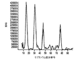
一旦、赤色ケプストラム及び赤外ケプストラムが得られると、別個の次にそれら赤色ケプストラム及び赤外ケプストラムは、患者の脈拍数に関連するピークについて検討される(270)。この点に関して、各ケプストラムの最も顕著な(すなわち最大の)ピークが識別され得る。各ケプストラムの最も顕著なピークの位置は、ケプストラムが得られるプレチスモグラフ波形の基本周波数を示す。プレチスモグラフ波形の基本周波数は患者の脈拍数に比例するので、患者の脈拍数はケプストラムの一方または双方から推定する(280)ことができる。例えば、図3Bの赤色ケプストラムの最も顕著なピークは、1分当たり約65拍動のケプストラムベースの脈拍数推定値に対応するFFTスペクトルの20番目の区分の近傍で生じる。ここでこの推定値は、図3Aに示す1分当たり61拍動の赤色光使用の時間領域プレチスモグラフ波形から得られる従来の時間領域ベースの推定値とはわずかに異なることに注目されたい。脈拍数推定値は赤色ケプストラム及び赤外ケプストラムの双方から得られ、個々の推定値を相互に関連付けることにより患者脈拍数の単一の推定値を得ることができる。また、患者の脈拍数をケプストラムの一方または双方からの情報のみに基づいて推定することが可能であるが、患者の脈拍数の時間領域ベースの推定値を使用して初期識別を行なって、後続する脈拍数に関連するケプストラムピーク(ケフレンシー:Quefrency)の追跡をサポートすることもできる。 Once the red and infrared cepstrum are obtained, the red and infrared cepstrum are then examined for peaks associated with the patient's pulse rate (270). In this regard, the most prominent (ie, largest) peak of each cepstrum can be identified. The position of the most prominent peak in each cepstrum indicates the fundamental frequency of the plethysmograph waveform from which the cepstrum is obtained. Since the fundamental frequency of the plethysmograph waveform is proportional to the patient's pulse rate, the patient's pulse rate can be estimated 280 from one or both of the cepstrum. For example, the most prominent peak of the red cepstrum in FIG. 3B occurs near the 20th section of the FFT spectrum corresponding to a cepstrum-based pulse rate estimate of approximately 65 beats per minute. Note that this estimate is slightly different from the conventional time domain based estimate obtained from the time domain plethysmographic waveform with 61 beats per minute red light shown in FIG. 3A. Pulse rate estimates are obtained from both the red and infrared cepstrum and a single estimate of the patient's pulse rate can be obtained by correlating individual estimates. It is also possible to estimate the patient's pulse rate based solely on information from one or both of the cepstrum, but use a time domain based estimate of the patient's pulse rate to make subsequent identifications. It is also possible to support tracking of cepstrum peaks (Quefrency) related to the pulse rate to be performed.
ケプストラムの一方または双方に顕著なピークが無い場合もある。例えば、図3Dは、生理的信号が無い(例えば、プレチスモグラフプローブが患者の指から取り外された)状態において典型的に見られる赤外時間領域プレチスモグラフ信号を示し、図3Eは、図3Dの赤外時間領域プレチスモグラフ信号に関して得られる赤外パワースペクトル及びケプストラムを示している。図3Eのパワースペクトルは、図3B及び3Cに示すパワースペクトルのような患者の生理的信号状態において典型的に見られるパワースペクトルとは幾分異なるが、図3B及び3Cの実に顕著なケプストラムピークに比べると図3Eのケプストラムには顕著なピークは見られないので、患者の生理的信号が無いことは、特にケプス
トラムの検討から明らかである。
There may be no significant peak in one or both of the cepstrum. For example, FIG. 3D shows an infrared time domain plethysmographic signal typically seen in the absence of a physiological signal (eg, the plethysmograph probe has been removed from the patient's finger), and FIG. 3E shows the infrared of FIG. Figure 5 shows the infrared power spectrum and cepstrum obtained for a time domain plethysmographic signal. The power spectrum of FIG. 3E is somewhat different from the power spectrum typically seen in a patient's physiological signal conditions, such as the power spectrum shown in FIGS. 3B and 3C, but with the very prominent cepstrum peaks of FIGS. 3B and 3C. In comparison, the cepstrum in FIG. 3E does not have a significant peak, so it is clear from the cepstrum study that there is no patient physiological signal.
患者の脈拍数に関連するピークのケプストラムの検討に加えて、ステップ(270)では、赤色ケプストラム及び赤外ケプストラムをモーションアーチファクトに関連するピークについて検討する。通常、モーションアーチファクトに関連する赤色ケプストラム及び赤外ケプストラムのピークは患者の脈拍数に関連するピークほど顕著ではない。各ケプストラムのさほど顕著ではないピークの位置(複数の位置)は、このケプストラムが得られるプレチスモグラフ波形に含まれるモーションアーチファクトに関する示唆を与え、この情報に基づいて、赤色プレチスモグラフ信号及び赤外プレチスモグラフ信号に含まれるモーションアーチファクトの周波数を推定することができる(290)。 In addition to reviewing the peak cepstrum associated with the patient's pulse rate, step (270) examines the red and infrared cepstrum for peaks associated with motion artifacts. Typically, the red and infrared cepstrum peaks associated with motion artifacts are not as prominent as the peaks associated with the patient's pulse rate. The less prominent peak position (several positions) of each cepstrum gives suggestions on motion artifacts contained in the plethysmographic waveform from which this cepstrum is obtained, and based on this information, it is included in the red and infrared plethysmographic signals. The frequency of motion artifacts to be estimated can be estimated (290).
一旦、脈拍数の推定値が得られると、この脈拍数情報を使用してフィルタを構成して、入力赤色光信号及び入力赤外光信号からノイズ及びモーションアーチファクトを除去する。これは、時間領域で赤色信号及び赤外信号に適用される適応バンドパスフィルタを使用して行なうことができ、このフィルタではカットオフ周波数がケプストラム領域で特定されるパルス周波数により決定される。別の構成として、図2の実施形態に示すように、赤色周波数領域プレチスモグラフ信号及び赤外周波数領域プレチスモグラフ信号を、第1段階FFT後に、ケプストラム領域から得られるパルス周波数情報を使用して構成する周波数領域フィルタによって、周波数領域でフィルタリングすることができる(300)。逆高速フーリェ変換(IFFT)操作をフィルタリング処理した周波数領域信号に対して行なって(310)フィルタリング処理した赤色時間領域プレチスモグラフ信号及び赤外時間領域プレチスモグラフ信号を取得し、これらの信号は、時間領域の赤色入力信号及び赤外入力信号を使用する回帰分析をベースとするSPO2推定のような後続の処理に使用される。赤色信号及び赤外信号からノイズを除去することにより、回帰分析をベースとするSPO2推定のような後続の処理が改善される。 Once the pulse rate estimate is obtained, this pulse rate information is used to construct a filter to remove noise and motion artifacts from the input red light signal and the input infrared light signal. This can be done using an adaptive bandpass filter applied to the red and infrared signals in the time domain, where the cutoff frequency is determined by the pulse frequency specified in the cepstrum domain. As another configuration, as shown in the embodiment of FIG. 2, the frequency formed by using the pulse frequency information obtained from the cepstrum region after the first stage FFT for the red frequency domain plethysmograph signal and the infrared frequency domain plethysmograph signal. A domain filter can filter in the frequency domain (300). An inverse fast Fourier transform (IFFT) operation is performed on the filtered frequency domain signal (310) to obtain filtered red time domain plethysmographic signal and infrared time domain plethysmographic signal, Used for subsequent processing such as SPO2 estimation based on regression analysis using red and infrared input signals. By removing noise from the red and infrared signals, subsequent processing such as SPO2 estimation based on regression analysis is improved.
さらに、スペクトル領域及びケプストラム領域の双方における情報を使用してSPO2に関する指標が得られる。赤色プレチスモグラフ信号及び赤外プレチスモグラフ信号の全体としてのDCレベルは第1段階スペクトルから決定することができ、脈拍の周波数に対応するケプストラムピークの相対振幅を使用して赤色プレチスモグラフ信号及び赤外プレチスモグラフ信号のACレベルに関する指標が得られる。この点に関して、次の計算式を利用することができる。 In addition, an index for SPO2 is obtained using information in both the spectral and cepstrum domains. The overall DC level of the red and infrared plethysmographic signals can be determined from the first stage spectrum and the relative amplitude of the cepstrum peak corresponding to the pulse frequency is used to determine the red and infrared plethysmographic signal. Indicators on AC levels are obtained. In this regard, the following formula can be used.
R’=AC(ケプストラム−赤色)/DC(スペクトル−赤色)/AC(ケプストラム−赤外)/DC(ケプストラム−赤外)
または、別の計算式で表わすことができる。
R ′ = AC (cepstrum-red) / DC (spectrum-red) / AC (cepstrum-infrared) / DC (cepstrum-infrared)
Alternatively, it can be expressed by another calculation formula.
R’=AC(ケプストラム−赤色)/DC(スペクトル−赤色)×DC(スペクトル赤外)/AC(ケプストラム−赤外)
ここで、AC(ケプストラム−赤色)は赤色ケプストラムから得られる赤色プレチスモグラフ信号のACレベルであり、DC(スペクトル−赤色)は赤色スペクトルから得られる赤色プレチスモグラフ信号のDCレベルであり、AC(ケプストラム−赤外)は赤外ケプストラムから得られる赤外プレチスモグラフ信号のACレベルであり、DC(スペクトル−赤外)は赤外スペクトルから得られる赤外プレチスモグラフ信号のDCレベルである。次に、生成された指標R’を使用して、患者のSPO2レベルを既知の回帰技術と同様な方法で推定する(320)ことができる。この回帰技術ではAC及びDC推定値が時間領域の赤色信号及び赤外信号から得られる。このような既知の回帰技術の一例は、「パルスオキシメータによるSPO2判定システム(SYSTEM FOR PULSE OXIMETRY SPO2 DETERMINATION)」と題される米国特許第5,934,277号に開示されており、この文献はその全体が開示されることにより本発明の開
示に含まれる。
R ′ = AC (cepstrum-red) / DC (spectrum-red) × DC (spectral infrared) / AC (cepstrum-infrared)
Here, AC (cepstrum-red) is the AC level of the red plethysmograph signal obtained from the red cepstrum, DC (spectrum-red) is the DC level of the red plethysmograph signal obtained from the red spectrum, and AC (cepstrum-red). (Ex) is the AC level of the infrared plethysmograph signal obtained from the infrared cepstrum, and DC (spectrum-infrared) is the DC level of the infrared plethysmograph signal obtained from the infrared spectrum. The generated index R ′ can then be used to estimate 320 the patient's SPO2 level in a manner similar to known regression techniques. In this regression technique, AC and DC estimates are obtained from the red and infrared signals in the time domain. An example of such a known regression technique is disclosed in US Pat. No. 5,934,277, entitled “SYSTEM FOR PULSE OXIMETRY SPO2 DETERMINATION”, which is disclosed in US Pat. The entire disclosure is included in the disclosure of the present invention.
次に図4を参照すると、方法(400)の別の実施形態を示すブロック図が示されている。この方法においては、赤色時間領域プレチスモグラフ信号及び赤外時間領域プレチスモグラフ信号をケプストラム領域で処理して、患者の脈拍数及び血液分析レベル(例えばSPO2)情報のような患者の生理状態に関する所望の情報を取得する。図4に示すケプストラム領域プレチスモグラフ信号処理方法(200)は、図2に示す方法(200)と同様な態様で行なわれる。この点に関して、赤色プレチスモグラフ信号及び赤外プレチスモグラフ信号のような2つの連続時間領域プレチスモグラフ信号は、これらの信号を適切な周波数でサンプリングすることによってデジタル化される(410)。50Hzでサンプリングした代表的な赤色時間領域プレチスモグラフ信号及び赤外時間領域プレチスモグラフ信号を図5A及び図6Aに示す。図6Aの信号はモーションアーチファクトを含む。図2の方法(200)のように、ケプストラム領域処理方法(400)は特に、図1に関連して上に記載したようなパルスオキシメータ10のデジタルプロセッサ80が実行することができるソフトウェアで実施するのに適している。他の実施形態では、ケプストラム領域処理方法(400)は、非デジタル化プレチスモグラフ信号を処理するように構成することができ、適切なハードウェア構成要素で実行することができる。さらに、ケプストラム領域処理方法(400)は、2つよりも多くのプレチスモグラフ信号を同時に処理するように構成することができる。
Turning now to FIG. 4, a block diagram illustrating another embodiment of a method (400) is shown. In this method, the red time domain plethysmograph signal and the infrared time domain plethysmograph signal are processed in the cepstrum domain to provide desired information regarding the patient's physiological state, such as patient pulse rate and blood analysis level (eg, SPO2) information. get. The cepstrum region plethysmograph signal processing method (200) shown in FIG. 4 is performed in the same manner as the method (200) shown in FIG. In this regard, two continuous time domain plethysmographic signals, such as a red plethysmographic signal and an infrared plethysmographic signal, are digitized by sampling these signals at the appropriate frequency (410). Representative red time domain plethysmographic signals and infrared time domain plethysmographic signals sampled at 50 Hz are shown in FIGS. 5A and 6A. The signal in FIG. 6A includes motion artifacts. Like the method (200) of FIG. 2, the cepstrum region processing method (400) is particularly implemented in software that can be executed by the
デジタル化した赤色時間領域プレチスモグラフ信号及び赤外時間領域プレチスモグラフ信号を適切な平滑化ウィンドウ(例えば、Hanning,HammingまたはKaiser)を使用して平滑化し(420)、次に複素FFT(430)を使用して並列的に処理する。次に、第1段階FFTからの出力をデコードし、個々の赤色及び赤外エネルギースペクトル及び対数パワースペクトルを算出して、保存する(440,450)。図5A及び図6Aの赤色信号及び赤外信号に関して得られる赤色及び赤外エネルギースペクトル及び対数パワースペクトルのプロットをそれぞれ図5C及び図5D、並びに図6C及び図6Dに示す。次に、第2段階FFT(460)を対数パワースペクトルに適用して、その結果から赤色ケプストラム及び赤外ケプストラム(470)を取得する。必要に応じて、第1及び第2段階FFT演算の結果をスケーリングして、後続の演算における浮動小数点エラーの防止に役立てる。図5A及び図6Aの赤色信号及び赤外信号に関して得られる赤色ケプストラム及び赤外ケプストラムのプロットを図5E及び図6Eに示す。ケプストラム(ケフレンシーの次元を有する)のピークを検討し(480)、変換してパルス周波数の推定値を供給する。 The digitized red time domain plethysmograph signal and infrared time domain plethysmograph signal are smoothed (420) using an appropriate smoothing window (eg Hanning, Hamming or Kaiser) and then using a complex FFT (430). Process in parallel. Next, the output from the first stage FFT is decoded and individual red and infrared energy spectra and log power spectra are calculated and stored (440, 450). The red and infrared energy spectra and log power spectrum plots obtained for the red and infrared signals of FIGS. 5A and 6A are shown in FIGS. 5C and 5D, and FIGS. 6C and 6D, respectively. Next, a second stage FFT (460) is applied to the logarithmic power spectrum, and a red cepstrum and an infrared cepstrum (470) are obtained from the result. If necessary, the results of the first and second stage FFT operations are scaled to help prevent floating point errors in subsequent operations. The resulting red and infrared cepstrum plots for the red and infrared signals of FIGS. 5A and 6A are shown in FIGS. 5E and 6E. The peak of the cepstrum (having the quefrency dimension) is examined (480) and transformed to provide an estimate of the pulse frequency.
ケプストラムベースの脈拍数推定値をパルス調整モジュール(490)に供給する。パルス調整モジュール(490)はまた、エネルギースペクトル及び対数パワースペクトルのピーク分析に基づく患者の脈拍数推定値を受信する。加えて、時間領域脈拍数推定値を、デジタル化した赤色時間領域プレチスモグラフ信号及び赤外時間領域プレチスモグラフ信号から、微分、しきい値設定、及び最も共通して検出される間隔をピッキングすることのような従来技術を使用して抽出する(500)。図5A及び図6Aの赤色時間領域プレチスモグラフ信号及び赤外時間領域プレチスモグラフ信号から得られる微分波形のプロットを図5B及び図6Bに示す。また、時間領域ベースの脈拍数推定値を入力としてパルス調整モジュール(490)に供給する。 A cepstrum based pulse rate estimate is provided to the pulse adjustment module (490). The pulse adjustment module (490) also receives a patient's pulse rate estimate based on peak analysis of the energy spectrum and logarithmic power spectrum. In addition, time domain pulse rate estimates are picked from digitized red time domain plethysmograph signals and infrared time domain plethysmograph signals, derivatives, threshold settings, and most commonly detected intervals. Extract using conventional techniques (500). The differential waveform plots obtained from the red time domain plethysmograph signal and the infrared time domain plethysmograph signal of FIGS. 5A and 6A are shown in FIGS. 5B and 6B. In addition, a time domain based pulse rate estimate is provided as an input to the pulse adjustment module (490).
エネルギースペクトル及びエネルギーケプストラムのピークに関する情報をモーション区分兼モーション強度推定モジュール(510)に入力する。モーション区分兼モーション強度推定モジュール(510)は、赤色及び赤外のエネルギースペクトル及びエネルギーケプストラムのそれぞれのピークの振幅、相対位置及び間隔の全てを使用して、モーション区分判定及びモーション強度判定を行なう。簡単な指標区分及びモーション推定は、
ケプストラムピークの数及び間隔を使用することにより決定することができる。この点に関して、比較的明瞭なプレチスモグラフ信号により通常、一つの主要なケプストラムピークを生成することができる。ケプストラムピークの数及びサイズが大きくなると、相当大きなモーション要素の存在が推測される。モーション区分兼モーション強度推定モジュール(510)からの情報をアダプティブフィルタモジュール(520)及びパルス調整モジュール(490)の双方に入力する。
Information about the energy spectrum and energy cepstrum peaks is input to the motion segment and motion intensity estimation module (510). The motion segment and motion intensity estimation module (510) performs motion segment determination and motion intensity determination using all of the red, infrared energy spectrum and the amplitude, relative position and interval of each peak of the energy cepstrum. Simple index classification and motion estimation
It can be determined by using the number and interval of cepstrum peaks. In this regard, one major cepstrum peak can usually be generated by a relatively clear plethysmographic signal. As the number and size of cepstrum peaks increases, it can be assumed that there are significant motion elements. Information from the motion classification and motion intensity estimation module (510) is input to both the adaptive filter module (520) and the pulse adjustment module (490).
アダプティブフィルタモジュール(520)はパルス周波数の推定値及びモーションノイズ成分(が在る場合)の周波数分布を使用して周波数領域のフィルタリングを制御して、パルス基本周波数成分及び/又はその高調波の信号対ノイズ比を改善する。この点に関して、第1段階FFT(430)信号の後に得られる赤色周波数領域プレチスモグラフ信号及び赤外周波数領域プレチスモグラフ信号をフィルタリングして(530)、フィルタリング処理した赤色周波数領域プレチスモグラフ信号及び赤外周波数領域プレチスモグラフ信号を生成する。図5A及び図6Aの赤色時間領域プレチスモグラフ信号及び赤外時間領域プレチスモグラフ信号に対応するフィルタリング処理した赤色周波数領域プレチスモグラフ信号及び赤外周波数領域プレチスモグラフ信号のプロットを図5F及び図6Fに示す。有限インパルス応答(finite impulse response:FIR)フィルタ及び無限インパルス応答(infinite impulse response:IIR)フィルタの双方を含む多くの異なるタイプのフィルタを実現することができる。スペクトル法の一つの不利な点は、これらのスペクトル法が入力信号の高速変化を追跡するには向かないことである。しかしながら、本方法(400)では、スペクトル情報を使用してアダプティブフィルタを制御する。時間領域パルス測定技術をこのフィルタからの出力信号に使用することにより、かなり速い変化を追跡する能力が得られる。 The adaptive filter module (520) uses the frequency distribution of the pulse frequency estimate and the motion noise component (if present) to control frequency domain filtering to provide a signal for the pulse fundamental frequency component and / or its harmonic signal. Improve the noise-to-noise ratio. In this regard, the red frequency domain plethysmograph signal and infrared frequency domain plethysmograph signal obtained after the first stage FFT (430) signal are filtered (530), and the filtered red frequency domain plethysmograph signal and infrared frequency domain plethysmograph are processed. Generate a signal. Plots of the filtered red frequency domain plethysmograph signal and infrared frequency domain plethysmograph signal corresponding to the red time domain plethysmograph signal and infrared time domain plethysmograph signal of FIGS. 5A and 6A are shown in FIGS. 5F and 6F. Many different types of filters can be implemented, including both finite impulse response (FIR) filters and infinite impulse response (IIR) filters. One disadvantage of spectral methods is that they are not suitable for tracking fast changes in the input signal. However, the method (400) uses spectral information to control the adaptive filter. By using a time domain pulse measurement technique on the output signal from this filter, the ability to track fairly fast changes is obtained.
逆FFT操作(540)を実行して、フィルタリング処理した赤色時間領域プレチスモグラフ信号及び赤外時間領域プレチスモグラフ信号を取得し、オーバーラップ及び加算操作(550)を実行して、DC成分が差し引かれ、かつモーション成分を減らしたプレチスモグラフ信号を再構成する。オーバーラップ及び加算操作(550)に続いて、フィルタリング処理した赤色信号及び赤外信号の双方のエネルギー成分を、例えば最小二乗法(root−mean−square (rms) measure)を使用して取得する(560)。これにより、赤色ACレベル及び赤外ACレベルの推定値が得られる。図4には示していないが、ケプストラム領域で表わされる赤色ACレベル及び赤外ACレベルの推定値を取得することもできる。赤色ケプストラム及び赤外ケプストラムの主要ピーク位置を周波数値に変換し、その周波数及び周波数の高調波のエネルギー値を赤色信号及び赤外信号の保存エネルギースペクトルを参照することにより取得する(すなわち積分する)ことができる。赤色及び赤外ケプストラムピークの相対振幅を使用してAC推定値を生成することも可能である。オーバーラップ及び加算操作(550)に続いて、別の従来の時間領域ベースのパルス推定をフィルタリング処理した赤色信号及び赤外信号に対しても行ない(570)、この推定値もパルス調整モジュール(490)に送信する。 Perform inverse FFT operation (540) to obtain filtered red time domain plethysmograph signal and infrared time domain plethysmograph signal, perform overlap and add operation (550), subtract DC component, and Reconstruct a plethysmograph signal with reduced motion components. Following the overlap and add operation (550), the energy components of both the filtered red and infrared signals are acquired using, for example, a root-mean-square (rms) measure ( 560). Thereby, the estimated values of the red AC level and the infrared AC level are obtained. Although not shown in FIG. 4, it is also possible to obtain estimated values of the red AC level and the infrared AC level represented by the cepstrum region. The main peak position of the red cepstrum and infrared cepstrum is converted into a frequency value, and energy values of harmonics of the frequency and frequency are obtained by referring to (ie, integrating) the stored energy spectra of the red signal and the infrared signal. be able to. It is also possible to generate AC estimates using the relative amplitudes of the red and infrared cepstrum peaks. Subsequent to the overlap and add operation (550), another conventional time domain based pulse estimation is also performed on the filtered red and infrared signals (570), and this estimate is also applied to the pulse adjustment module (490). ).
パルス調整器(490)は種々の時間領域、フィルタリング処理した時間領域、エネルギースペクトル、対数パワースペクトル、及びケプストラムベースのパルス推定値、及びモーション強度及び区分を使用して、患者の脈拍数の全体としての最良の推定値(580)を供給する。この点に関して、ある範囲のモーションの場合、主要ケプストラムピーク位置はパルス周波数の良好な推定値として十分に役に立つ。しかしながら、大きなモーションの振幅及び赤色プレチスモグラフ信号及び赤外プレチスモグラフ信号の波形と同様な波形を生じさせるモーションの場合、多くのパラメータを検討して競合する推定値の中から一つを決定する必要がある。特に、パルス調整モジュール(490)によって時間領域(フィルタリング処理済み、及びフィルタリング処理を行なっていないものの双方)、スペクトル領域(エネルギー及び対数パワーの双方)、及びケプストラム領域ベースのパル
ス推定値の相関性を検討し、モーション区分兼モーション強度推定モジュール(510)においてケプストラムから生成されるモーション推定を使用して、それぞれの脈拍数推定値に重み付けを行なう。大きなモーションが在る場合には、ケプストラム情報を使用して、競合するスペクトルパルス候補の間に分解する。この点に関して、「ノコギリ歯状」の典型的なパルス波形は、普通少なくとも2つの可視高調波ピークを有する主要基本スペクトルピークとなる。結果として得られるケプストラムは、基本周波数に関連する主要ピークである。従って、対応するケプストラムピークを持たないスペクトル候補は排除され得る。また、基本周波数ピーク近傍に競合ノイズが在る場合には、ケプストラムピークは、基本周波数ピーク及び関連する高調波のエネルギーまたは対数スペクトルを検討することにより確認することができる。前に記載したパルス調整プロセス(490)に加えて、パルス調整プロセス(490)用の神経網を用いることも可能である。
The pulse adjuster (490) uses various time domains, filtered time domain, energy spectrum, log power spectrum, and cepstrum-based pulse estimates, and motion intensity and segmentation as a whole for the patient's pulse rate. Provides the best estimate (580) of. In this regard, for a range of motions, the main cepstrum peak position serves well as a good estimate of the pulse frequency. However, for motion that produces large motion amplitudes and waveforms similar to those of the red and infrared plethysmograph signals, many parameters need to be considered to determine one of the competing estimates. . In particular, the correlation between the time domain (both filtered and unfiltered), spectral domain (both energy and log power), and cepstrum domain based pulse estimates by the pulse adjustment module (490). Consider and weight each pulse rate estimate using motion estimation generated from the cepstrum in the motion segment and motion intensity estimation module (510). If there is a large motion, cepstrum information is used to resolve between competing spectral pulse candidates. In this regard, a typical “sawtooth” pulse waveform will be the main fundamental spectral peak, usually with at least two visible harmonic peaks. The resulting cepstrum is the main peak associated with the fundamental frequency. Thus, spectral candidates that do not have a corresponding cepstrum peak can be excluded. Also, if there is competing noise in the vicinity of the fundamental frequency peak, the cepstrum peak can be confirmed by examining the fundamental frequency peak and the associated harmonic energy or logarithmic spectrum. In addition to the pulse adjustment process (490) described previously, it is also possible to use a neural network for the pulse adjustment process (490).
パルス調整モジュール(490)に用いることができる別の手法では、ケプストラムピークをエネルギースペクトルの領域またはチャネルに関連付け、AC値を取得し、次にSPO2推定値を生成する。このSPO2推定値は、許容パルス範囲(例えば、30〜350bpm)に渡る平均エネルギーから生成される別のSPO2推定値とすることができる。有効なケプストラム候補によってSPO2を平均エネルギーから生成される推定値として同様に経時的に追跡することができる。この情報を使用して、競合するケプストラム候補の中からパルス周波数に関連する一のケプストラムを決定することもできる。 Another approach that can be used in the pulse adjustment module (490) involves associating cepstrum peaks with regions or channels of the energy spectrum, obtaining AC values, and then generating SPO2 estimates. This SPO2 estimated value may be another SPO2 estimated value generated from the average energy over an allowable pulse range (for example, 30 to 350 bpm). SPO2 can also be tracked over time as an estimate generated from average energy by valid cepstrum candidates. This information can also be used to determine one cepstrum associated with the pulse frequency from among the competing cepstrum candidates.
患者の脈拍数の全体としての最良の推定値(580)を取得するのに加えて、図4のプレチスモグラフ信号処理方法(400)によれば、患者のSPO2レベルの推定値も生成される。赤色時間領域プレチスモグラフ信号及び赤外時間領域プレチスモグラフ信号のエネルギー成分は、例えば最小二乗法(rms)による変換を通して得られる(590)。これによって赤色DCレベル及び赤外DCレベルの推定値が得られる。赤色DCレベル及び赤外DCレベル(590)、及び赤色ACレベル及び赤外ACレベル(560)はSPO2モジュール(600)に供給される。図2に示す方法(200)のステップ(310)に関連する形で上に詳細に議論したように、SPO2モジュール(600)は赤色DCレベル及び赤外DCレベル、及び赤色ACレベル及び赤外ACレベルを使用して患者のSPO2レベルと相互に関連する指標を従来の回帰分析をベースとする技術と同様な方法で生成する。 In addition to obtaining an overall best estimate (580) of the patient's pulse rate, the plethysmographic signal processing method (400) of FIG. 4 also generates an estimate of the patient's SPO2 level. The energy components of the red time-domain plethysmograph signal and the infrared time-domain plethysmograph signal are obtained (590) through transformation, for example, by least squares (rms). This provides an estimate of the red and infrared DC levels. The red and infrared DC levels (590) and the red and infrared AC levels (560) are provided to the SPO2 module (600). As discussed in detail above in connection with step (310) of the method (200) shown in FIG. 2, the SPO2 module (600) has a red DC level and an infrared DC level, and a red AC level and an infrared AC level. The level is used to generate an index that correlates with the patient's SPO2 level in a manner similar to techniques based on conventional regression analysis.
本発明の種々の実施形態について詳細に記載してきたが、本発明をさらに変形し、適合させることが可能なことはこの技術分野の当業者であれば明らかである。しかしながら、このような変形及び適合は本発明の技術思想及び技術範囲に含まれるものであることは明白に理解されるものと考える。 Although various embodiments of the present invention have been described in detail, it will be apparent to those skilled in the art that the present invention can be further modified and adapted. However, it should be clearly understood that such modifications and adaptations are included in the technical spirit and scope of the present invention.
Claims (52)
前記第1の時間領域プレチスモグラフ信号に対してフーリェ変換を行なって前記第1のプレチスモグラフ信号を第1の周波数領域プレチスモグラフ信号に変換する工程と、
前記第2の時間領域プレチスモグラフ信号に対してフーリェ変換を行なって前記第2のプレチスモグラフ信号を第2の周波数領域プレチスモグラフ信号に変換する工程と、
第1パワースペクトルを前記第1の周波数領域プレチスモグラフ信号から算出する工程と、
第2パワースペクトルを前記第2の周波数領域プレチスモグラフ信号から算出する工程と、
前記第1パワースペクトルに対してフーリェ変換を行なって前記第1パワースペクトルを第1ケプストラムに変換する工程と、
前記第2パワースペクトルに対してフーリェ変換を行なって前記第2パワースペクトルを第2ケプストラムに変換する工程と、
前記第1及び第2ケプストラムを検討して、これらのケプストラムから前記患者の生理状態に関する情報を取得する工程とを備える方法。 A method of processing at least first and second time domain plethysmographic signals obtained from a patient comprising:
Performing a Fourier transform on the first time-domain plethysmograph signal to convert the first plethysmograph signal to a first frequency-domain plethysmograph signal;
Performing a Fourier transform on the second time domain plethysmograph signal to convert the second plethysmograph signal to a second frequency domain plethysmograph signal;
Calculating a first power spectrum from the first frequency domain plethysmograph signal;
Calculating a second power spectrum from the second frequency domain plethysmograph signal;
Performing a Fourier transform on the first power spectrum to convert the first power spectrum into a first cepstrum;
Performing a Fourier transform on the second power spectrum to convert the second power spectrum into a second cepstrum;
Reviewing the first and second cepstrum and obtaining information about the patient's physiological condition from these cepstrum.
前記患者の前記脈拍数に関連する前記第1ケプストラムのピークを特定し、
前記患者の前記脈拍数に関連する前記第2ケプストラムのピークを特定し、かつ
前記患者の前記脈拍数を前記第1及び第2ケプストラムの前記特定されたピークに基づいて推定する、請求項5記載の方法。 In the step of considering the first and second cepstrum,
Identifying the peak of the first cepstrum associated with the pulse rate of the patient;
6. The peak of the second cepstrum associated with the patient's pulse rate is identified, and the pulse rate of the patient is estimated based on the identified peak of the first and second cepstrum. the method of.
項6記載の方法。 Identifying the peak of the first cepstrum associated with the pulse rate of the patient and identifying the peak of the second cepstrum associated with the pulse rate of the patient in the time of the pulse rate of the patient The method of claim 6, further comprising utilizing region-based estimates.
前記第2パワースペクトルのDCレベルを決定する工程と、
前記第1の時間領域プレチスモグラフ信号のACレベルを前記第1ケプストラ ムの前記特定されたピークから取得する工程と、
前記第2の時間領域プレチスモグラフ信号のACレベルを前記第2ケプストラムの前記特定されたピークから取得する工程と、
前記患者の血液分析レベルと相互に関連する値を前記第1及び第2パワースペクトルの前記DC値、及び前記第1及び第2の時間領域プレチスモグラフ信号の前記ACレベルから算出する工程とをさらに含む、請求項6記載の方法。 Determining a DC level of the first power spectrum;
Determining a DC level of the second power spectrum;
Obtaining an AC level of the first time domain plethysmograph signal from the identified peak of the first cepstrum;
Obtaining an AC level of the second time-domain plethysmograph signal from the identified peak of the second cepstrum;
Calculating a value correlated with the blood analysis level of the patient from the DC value of the first and second power spectra and the AC level of the first and second time domain plethysmographic signals. The method according to claim 6.
赤外波長光信号を前記患者の組織部位を透過させて前記第2の時間領域プレチスモグラフ信号を取得する工程とをさらに含む、請求項1記載の方法。 Transmitting a red wavelength light signal through the tissue site of the patient to obtain the first time domain plethysmograph signal;
The method of claim 1, further comprising: passing an infrared wavelength light signal through the patient's tissue site to obtain the second time domain plethysmographic signal.
第2の時間領域プレチスモグラフ信号に含まれるモーションアーチファクトに関する情報を取得する工程をさらに含む、請求項1記載の方法。 The method of claim 1, further comprising: analyzing the number and interval of peaks included in the first and second cepstrum to obtain information on motion artifacts included in the first and second time domain plethysmographic signals. Method.
前記患者の前記脈拍数の時間領域ベースの推定値を前記時間領域プレチスモグラフ信号から取得する工程と、
前記時間領域プレチスモグラフ信号をスペクトル領域プレチスモグラフ信号に変換する工程と、
前記患者の前記脈拍数のスペクトル領域ベースの推定値を前記スペクトル領域プレチスモグラフ信号から取得する工程と、
前記スペクトル領域プレチスモグラフ信号をケプストラム領域プレチスモグラフ信号に変換する工程と、
前記患者の前記脈拍数のケプストラム領域ベースの推定値を前記ケプストラム領域プレチスモグラフ信号から取得する工程と、
前記患者の前記脈拍数の最良の推定値を少なくとも前記患者の前記脈拍数の前記時間領域ベースの推定値、スペクトル領域ベースの推定値及びケプストラム領域ベースの推定値に基づいて決定する工程と、を備える方法。 A method for determining a patient's pulse rate from at least one time domain plethysmographic signal obtained from said patient comprising:
Obtaining a time domain based estimate of the pulse rate of the patient from the time domain plethysmograph signal;
Converting the time domain plethysmograph signal to a spectral domain plethysmograph signal;
Obtaining a spectral domain based estimate of the pulse rate of the patient from the spectral domain plethysmograph signal;
Converting the spectral domain plethysmographic signal into a cepstrum domain plethysmographic signal;
Obtaining a cepstrum region based estimate of the pulse rate of the patient from the cepstrum region plethysmograph signal;
Determining a best estimate of the pulse rate of the patient based at least on the time domain based estimate, spectral domain based estimate and cepstrum domain based estimate of the patient pulse rate. How to prepare.
前記時間領域プレチスモグラフ信号に含まれるモーションアーチファクトに関する前記情報を前記患者の前記脈拍数の最良の推定値を決定する前記工程に取り入れることによって、前記患者の前記脈拍数の前記最良の推定値が、少なくとも前記患者の前記脈拍数の前記時間領域ベースの推定値、スペクトル領域ベースの推定値及びケプストラム領域ベースの推定値及び前記時間領域プレチスモグラフ信号に含まれるモーションアーチファクトに関する情報に基づくものとなる工程とをさらに含む、請求項21記載の方法。 Generating information about motion artifacts included in the time domain plethysmograph from at least the spectral domain plethysmograph signal and the cepstrum domain plethysmograph signal;
By incorporating the information regarding motion artifacts contained in the time-domain plethysmographic signal into the step of determining the best estimate of the patient's pulse rate, the best estimate of the patient's pulse rate is at least Further comprising: based on the time domain based estimate of the pulse rate of the patient, a spectral domain based estimate and a cepstrum domain based estimate and information regarding motion artifacts contained in the time domain plethysmograph signal. 22. The method of claim 21, comprising.
タを構成する工程と、
前記スペクトル領域プレチスモグラフ信号に対して前記フィルタによりフィルタリングを行なって、フィルタリング処理したスペクトル領域プレチスモグラフ信号を取得する工程と、
前記フィルタリング処理したスペクトル領域プレチスモグラフ信号をフィルタリング処理した時間領域プレチスモグラフ信号に変換する工程と、
前記患者の前記脈拍数のフィルタリング処理した時間領域ベースの推定値を前記フィルタリング処理した時間領域プレチスモグラフ信号から取得する工程と、
前記患者の前記脈拍数の前記フィルタリング処理した時間領域ベースの推定値を、前記患者の前記脈拍数の最良の推定値を決定する工程に取り入れることによって、前記患者の前記脈拍数の前記最良の推定値が、少なくとも前記患者の前記脈拍数の時間領域ベースの推定値、スペクトル領域ベースの推定値、ケプストラム領域ベースの推定値、及びフィルタリング処理した時間領域ベースの推定値、及び前記時間領域プレチスモグラフ信号に含まれるモーションアーチファクトに関する情報に基づくものとなる工程とをさらに含む、請求項27記載の方法。 Configuring a frequency domain filter to remove motion artifacts based at least on the best estimate of the pulse rate of the patient, the spectral domain plethysmographic signal, and information on motion artifacts contained in the time domain plethysmographic signal; ,
Filtering the spectral domain plethysmograph signal with the filter to obtain a filtered spectral domain plethysmograph signal;
Converting the filtered spectral domain plethysmograph signal to a filtered time domain plethysmographic signal;
Obtaining a filtered time domain based estimate of the pulse rate of the patient from the filtered time domain plethysmograph signal;
The best estimate of the patient's pulse rate by incorporating the filtered time-domain based estimate of the patient's pulse rate into a step of determining the best estimate of the patient's pulse rate. The values are at least a time domain based estimate of the pulse rate of the patient, a spectral domain based estimate, a cepstrum domain based estimate, and a filtered time domain based estimate, and the time domain plethysmograph signal. 28. The method of claim 27, further comprising the step of being based on information regarding included motion artifacts.
前記患者の前記脈拍数の対数変換されたスペクトル領域ベースの推定値を前記対数変換されたスペクトル領域プレチスモグラフ信号から取得する工程と、
前記患者の前記脈拍数の前記対数変換されたスペクトル領域ベースの推定値を前記患者の前記脈拍数の最良の推定値を決定する前記工程に取り入れることによって、前記患者の前記脈拍数の前記最良の推定値が、少なくとも前記患者の前記脈拍数の時間領域ベースの推定値、スペクトル領域ベースの推定値、ケプストラム領域ベースの推定値、フィルタリング処理した時間領域ベースの推定値及び対数変換されたスペクトル領域ベースの推定値、及び前記時間領域プレチスモグラフ信号に含まれるモーションアーチファクトに関する前記情報に基づくものとなる工程とをさらに含む、請求項28記載の方法。 Prior to converting the spectral domain plethysmographic signal into a cepstrum domain plethysmographic signal, scaling the spectral domain plethysmographic signal with a logarithmic function to obtain a log-transformed spectral domain plethysmographic signal;
Obtaining a logarithmically transformed spectral domain-based estimate of the pulse rate of the patient from the logarithmically transformed spectral domain plethysmograph signal;
Incorporating the log-transformed spectral domain-based estimate of the patient's pulse rate into the step of determining the best estimate of the patient's pulse rate, the best of the patient's pulse rate. Estimates are at least a time domain based estimate of the pulse rate of the patient, a spectral domain based estimate, a cepstrum domain based estimate, a filtered time domain based estimate and a log transformed spectral domain base 30. The method of claim 28, further comprising: based on an estimate of the information and the information regarding motion artifacts included in the time domain plethysmographic signal.
前記第1波長とは異なる第2波長により特徴付けられる光信号を放出するように動作する第2光信号源と、
前記第1及び第2光信号源を動作させて前記第1及び第2光信号源の各々がそれぞれ第1及び第2光信号を多重化方法に従って放出するように動作可能である駆動システムと、
前記第1及び第2光信号が患者の患者組織部位によって減衰した後に、前記第1及び第2光信号を受信するように動作可能である検出器であって、さらに前記減衰した第1及び第2光信号を表わすアナログ検出器出力信号を供給するように動作可能である検出器と、
前記アナログ検出器出力信号を所望のサンプリングレートでサンプリングし、前記減衰した第1及び第2光信号を表わす一連のサンプリング値を有するデジタル信号を出力するように動作可能であるデジタルサンプラーと、
前記一連のサンプリング値を逆多重化して第1及び第2の時間領域プレチスモグラフ信号とし、前記第1及び第2の時間領域プレチスモグラフ信号を第1及び第2スペクトル領域プレチスモグラフ信号に変換し、前記第1及び第2スペクトル領域プレチスモグラフ信号を第1及び第2ケプストラム領域プレチスモグラフ信号に変換し、さらに前記第1及び第2ケプストラム領域プレチスモグラフ信号を検討してこれらの信号から前記患者の生理
状態に関する情報を取得することが可能であるデジタルプロセッサとを備えるパルスオキシメータ。 A first optical signal source operable to emit an optical signal characterized by a first wavelength;
A second optical signal source operable to emit an optical signal characterized by a second wavelength different from the first wavelength;
A drive system operable to operate the first and second optical signal sources so that each of the first and second optical signal sources emits first and second optical signals, respectively, according to a multiplexing method;
A detector operable to receive the first and second optical signals after the first and second optical signals are attenuated by a patient tissue site of a patient, further comprising the attenuated first and second attenuated first and second optical signals; A detector operable to provide an analog detector output signal representative of the two optical signals;
A digital sampler operable to sample the analog detector output signal at a desired sampling rate and to output a digital signal having a series of sampling values representing the attenuated first and second optical signals;
The series of sampling values are demultiplexed into first and second time domain plethysmographic signals, the first and second time domain plethysmographic signals are converted to first and second spectral domain plethysmographic signals, and the first And converting the second spectral domain plethysmographic signal into first and second cepstrum domain plethysmographic signals, and further examining the first and second cepstrum domain plethysmographic signals to obtain information on the patient's physiological condition from these signals. A pulse oximeter comprising a digital processor that is capable of.
前記時間領域プレチスモグラフ信号をスペクトル領域プレチスモグラフ信号に変換する工程と、
前記スペクトル領域プレチスモグラフ信号をケプストラム領域プレチスモグラフ信号に変換する工程と、
前記スペクトル領域プレチスモグラフ信号及びケプストラム領域プレチスモグラフ信号を検討して、対応するスペクトル領域プレチスモグラフ信号ピーク及びケプストラム領域プレチスモグラフ信号ピークを特定する工程と、
前記特定した対応スペクトル領域プレチスモグラフ信号ピーク及びケプストラム領域プレチスモグラフ信号ピークを使用して、前記基本パルス周波数を前記患者の基本パルス周波数に対する複数の可能な候補の中から選択する工程と、を備える方法。 A pulse adjustment method used in determining a basic pulse frequency of a patient from a plurality of signal regions associated with at least one time-domain plethysmographic signal obtained from the patient,
Converting the time domain plethysmograph signal to a spectral domain plethysmograph signal;
Converting the spectral domain plethysmographic signal into a cepstrum domain plethysmographic signal;
Examining the spectral domain plethysmographic signal and the cepstrum domain plethysmographic signal to identify corresponding spectral domain plethysmographic signal peaks and cepstrum domain plethysmographic signal peaks;
Using the identified corresponding spectral domain plethysmographic signal peak and cepstrum domain plethysmographic signal peak to select the fundamental pulse frequency from among a plurality of possible candidates for the patient fundamental pulse frequency.
前記時間領域プレチスモグラフ信号から取得した前記患者の基本パルス周波数の候補を、前記特定した対応スペクトル領域プレチスモグラフ信号ピーク及びケプストラム領域プレチスモグラフ信号ピークを使用して前記基本パルス周波数を選択する工程における前記患者の基本パルス周波数の複数の候補に含める工程とをさらに含む、請求項45記載の方法。 Obtaining at least one candidate for the patient's fundamental pulse frequency from the time domain plethysmographic signal;
The patient base pulse in the step of selecting the basic pulse frequency using the identified corresponding spectral domain plethysmographic signal peak and cepstrum domain plethysmographic signal peak as candidates for the basic pulse frequency of the patient obtained from the time domain plethysmographic signal 46. The method of claim 45, further comprising the step of including in a plurality of pulse frequency candidates.
前記患者の前記パルス周波数の少なくとも一つの候補を前記対数変換されたスペクトル領域プレチスモグラフ信号から取得する工程と、
前記対数変換されたスペクトル領域プレチスモグラフ信号から取得した前記患者の基本パルス周波数の候補を、前記特定した対応するスペクトル領域プレチスモグラフ信号ピーク及びケプストラム領域プレチスモグラフ信号ピークを使用して前記基本パルス周波数を選択する工程における前記患者の基本パルス周波数の複数の候補に含める工程とをさらに含む、請求項45記載の方法。 Scaling the spectral domain plethysmographic signal with a logarithmic function to obtain a logarithmically transformed spectral domain plethysmographic signal;
Obtaining at least one candidate for the pulse frequency of the patient from the logarithmically transformed spectral domain plethysmograph signal;
Selecting the basic pulse frequency candidate of the patient obtained from the logarithmically transformed spectral domain plethysmographic signal using the identified corresponding spectral domain plethysmographic signal peak and cepstrum domain plethysmographic signal peak. 46. The method of claim 45, further comprising including in a plurality of candidates for the patient's fundamental pulse frequency at.
前記スペクトル領域プレチスモグラフ信号から取得した前記患者の基本パルス周波数の候補を、前記特定した対応するスペクトル領域プレチスモグラフ信号ピーク及びケプストラム領域プレチスモグラフ信号ピークを使用して、前記基本パルス周波数を選択する工程における前記患者の基本パルス周波数の複数の候補に含める工程とをさらに含む、請求項45記載の方法。 Obtaining at least one candidate for the fundamental pulse frequency of the patient from the spectral domain plethysmographic signal;
The patient in the step of selecting the fundamental pulse frequency using the identified corresponding spectral domain plethysmographic signal peak and cepstrum domain plethysmographic signal peak as candidates for the basic pulse frequency of the patient obtained from the spectral domain plethysmographic signal 46. The method of claim 45, further comprising the step of including in a plurality of candidates for a fundamental pulse frequency of
前記ケプストラム領域プレチスモグラフ信号から取得した前記患者の基本パルス周波数の候補を、前記特定した対応するスペクトル領域プレチスモグラフ信号ピーク及びケプストラム領域プレチスモグラフ信号ピークを使用して前記基本パルス周波数を選択する工程における前記患者の基本パルス周波数の複数の候補に含める工程とをさらに含む、請求項45記載の方法。 Obtaining at least one candidate for the fundamental pulse frequency of the patient from the cepstrum domain plethysmograph signal;
The patient's fundamental pulse frequency candidates obtained from the cepstrum domain plethysmograph signal are selected from the patient in the step of selecting the fundamental pulse frequency using the identified corresponding spectral domain plethysmographic signal peak and cepstrum domain plethysmographic signal peak. 46. The method of claim 45, further comprising including in a plurality of candidates for a fundamental pulse frequency.
前記スペクトル領域プレチスモグラフ信号を前記周波数領域フィルタでフィルタリングして、フィルタリング処理したスペクトル領域プレチスモグラフ信号を取得する工程と、
前記フィルタリング処理したスペクトル領域プレチスモグラフ信号をフィルタリング処理した時間領域プレチスモグラフ信号に変換する工程と、
前記患者の前記基本パルス周波数の少なくとも一つの候補を前記フィルタリング処理した時間領域プレチスモグラフ信号から取得する工程と、
前記フィルタリング処理した時間領域プレチスモグラフ信号から取得した前記患者の基本パルス周波数の候補を、前記特定した対応するスペクトル領域プレチスモグラフ信号ピーク及びケプストラム領域プレチスモグラフ信号ピークを使用して前記基本パルス周波数を選択する工程における前記患者の基本パルス周波数の複数の候補に含める工程とをさらに含む、請求項45記載の方法。 Motion artifacts based on at least the basic pulse frequency of the patient, the spectral domain plethysmographic signal, and information about motion artifacts in the time domain plethysmographic signal generated from at least the spectral domain plethysmographic signal and the cepstrum domain plethysmographic signal. Configuring a frequency domain filter to be removed;
Filtering the spectral domain plethysmographic signal with the frequency domain filter to obtain a filtered spectral domain plethysmographic signal;
Converting the filtered spectral domain plethysmograph signal to a filtered time domain plethysmographic signal;
Obtaining at least one candidate for the fundamental pulse frequency of the patient from the filtered time domain plethysmographic signal;
Selecting the fundamental pulse frequency of the patient obtained from the filtered time domain plethysmograph signal using the identified corresponding spectral domain plethysmographic signal peak and cepstrum domain plethysmographic signal peak 46. The method of claim 45, further comprising including in a plurality of candidates for the patient's fundamental pulse frequency.
Applications Claiming Priority (2)
| Application Number | Priority Date | Filing Date | Title |
|---|---|---|---|
| US35901802P | 2002-02-22 | 2002-02-22 | |
| PCT/US2003/005181 WO2003071941A1 (en) | 2002-02-22 | 2003-02-21 | Cepstral domain pulse oximetry |
Publications (1)
| Publication Number | Publication Date |
|---|---|
| JP2005518238A true JP2005518238A (en) | 2005-06-23 |
Family
ID=27766033
Family Applications (1)
| Application Number | Title | Priority Date | Filing Date |
|---|---|---|---|
| JP2003570692A Pending JP2005518238A (en) | 2002-02-22 | 2003-02-21 | Cepstrum region pulse oximeter |
Country Status (5)
| Country | Link |
|---|---|
| US (2) | US6650918B2 (en) |
| EP (1) | EP1485015A1 (en) |
| JP (1) | JP2005518238A (en) |
| AU (1) | AU2003216348A1 (en) |
| WO (1) | WO2003071941A1 (en) |
Cited By (6)
| Publication number | Priority date | Publication date | Assignee | Title |
|---|---|---|---|---|
| JP2011524196A (en) * | 2008-06-16 | 2011-09-01 | コーニンクレッカ フィリップス エレクトロニクス エヌ ヴィ | Monitoring patient vital parameters using "IN-SITU" modulation scheme to avoid interference |
| JP2011215027A (en) * | 2010-03-31 | 2011-10-27 | National Institute Of Advanced Industrial Science & Technology | Positioning system and positioning method using pyroelectric infrared sensor array |
| JP2012504022A (en) * | 2008-09-26 | 2012-02-16 | クゥアルコム・インコーポレイテッド | Method and apparatus for undersampled collection and transmission of photoelectric pulse wave (PPG) data and reconstruction of full band PPG data at a receiver |
| JP2013506523A (en) * | 2009-10-06 | 2013-02-28 | コーニンクレッカ フィリップス エレクトロニクス エヌ ヴィ | Method and system for obtaining a first signal for analysis to characterize at least one periodic component of the first signal |
| WO2019202971A1 (en) * | 2018-04-17 | 2019-10-24 | ソニー株式会社 | Biometric information evaluating device and biometric information evaluating method |
| JP2023551585A (en) * | 2021-01-21 | 2023-12-08 | コーニンクレッカ フィリップス エヌ ヴェ | Arterial oxygenation measurement |
Families Citing this family (114)
| Publication number | Priority date | Publication date | Assignee | Title |
|---|---|---|---|---|
| US6018673A (en) | 1996-10-10 | 2000-01-25 | Nellcor Puritan Bennett Incorporated | Motion compatible sensor for non-invasive optical blood analysis |
| US9468378B2 (en) | 1997-01-27 | 2016-10-18 | Lawrence A. Lynn | Airway instability detection system and method |
| US8932227B2 (en) | 2000-07-28 | 2015-01-13 | Lawrence A. Lynn | System and method for CO2 and oximetry integration |
| US9042952B2 (en) | 1997-01-27 | 2015-05-26 | Lawrence A. Lynn | System and method for automatic detection of a plurality of SPO2 time series pattern types |
| US9521971B2 (en) | 1997-07-14 | 2016-12-20 | Lawrence A. Lynn | System and method for automatic detection of a plurality of SPO2 time series pattern types |
| US20070191697A1 (en) | 2006-02-10 | 2007-08-16 | Lynn Lawrence A | System and method for SPO2 instability detection and quantification |
| US6675031B1 (en) | 1999-04-14 | 2004-01-06 | Mallinckrodt Inc. | Method and circuit for indicating quality and accuracy of physiological measurements |
| US9053222B2 (en) | 2002-05-17 | 2015-06-09 | Lawrence A. Lynn | Patient safety processor |
| US20060195041A1 (en) | 2002-05-17 | 2006-08-31 | Lynn Lawrence A | Centralized hospital monitoring system for automatically detecting upper airway instability and for preventing and aborting adverse drug reactions |
| US6748254B2 (en) | 2001-10-12 | 2004-06-08 | Nellcor Puritan Bennett Incorporated | Stacked adhesive optical sensor |
| US7020507B2 (en) * | 2002-01-31 | 2006-03-28 | Dolphin Medical, Inc. | Separating motion from cardiac signals using second order derivative of the photo-plethysmogram and fast fourier transforms |
| JP2005518238A (en) * | 2002-02-22 | 2005-06-23 | デイテックス−オーメダ インコーポレイテッド | Cepstrum region pulse oximeter |
| US7190986B1 (en) | 2002-10-18 | 2007-03-13 | Nellcor Puritan Bennett Inc. | Non-adhesive oximeter sensor for sensitive skin |
| US7740591B1 (en) * | 2003-12-01 | 2010-06-22 | Ric Investments, Llc | Apparatus and method for monitoring pressure related changes in the extra-thoracic arterial circulatory system |
| US7194292B2 (en) * | 2004-02-25 | 2007-03-20 | General Electric Company | Simultaneous signal attenuation measurements utilizing frequency orthogonal random codes |
| US7162288B2 (en) | 2004-02-25 | 2007-01-09 | Nellcor Purtain Bennett Incorporated | Techniques for detecting heart pulses and reducing power consumption in sensors |
| US7194293B2 (en) | 2004-03-08 | 2007-03-20 | Nellcor Puritan Bennett Incorporated | Selection of ensemble averaging weights for a pulse oximeter based on signal quality metrics |
| EP1611847A1 (en) * | 2004-06-28 | 2006-01-04 | Datex-Ohmeda, Inc. | Validating pulse oximetry signals in the potential presence of artifact |
| US7343186B2 (en) * | 2004-07-07 | 2008-03-11 | Masimo Laboratories, Inc. | Multi-wavelength physiological monitor |
| US7590439B2 (en) | 2005-08-08 | 2009-09-15 | Nellcor Puritan Bennett Llc | Bi-stable medical sensor and technique for using the same |
| US7657295B2 (en) | 2005-08-08 | 2010-02-02 | Nellcor Puritan Bennett Llc | Medical sensor and technique for using the same |
| US7657294B2 (en) | 2005-08-08 | 2010-02-02 | Nellcor Puritan Bennett Llc | Compliant diaphragm medical sensor and technique for using the same |
| US20070060808A1 (en) | 2005-09-12 | 2007-03-15 | Carine Hoarau | Medical sensor for reducing motion artifacts and technique for using the same |
| US7725146B2 (en) | 2005-09-29 | 2010-05-25 | Nellcor Puritan Bennett Llc | System and method for pre-processing waveforms |
| US7725147B2 (en) | 2005-09-29 | 2010-05-25 | Nellcor Puritan Bennett Llc | System and method for removing artifacts from waveforms |
| US7899510B2 (en) | 2005-09-29 | 2011-03-01 | Nellcor Puritan Bennett Llc | Medical sensor and technique for using the same |
| US7869850B2 (en) | 2005-09-29 | 2011-01-11 | Nellcor Puritan Bennett Llc | Medical sensor for reducing motion artifacts and technique for using the same |
| US8092379B2 (en) | 2005-09-29 | 2012-01-10 | Nellcor Puritan Bennett Llc | Method and system for determining when to reposition a physiological sensor |
| US7904130B2 (en) | 2005-09-29 | 2011-03-08 | Nellcor Puritan Bennett Llc | Medical sensor and technique for using the same |
| US7483731B2 (en) | 2005-09-30 | 2009-01-27 | Nellcor Puritan Bennett Llc | Medical sensor and technique for using the same |
| US7486979B2 (en) | 2005-09-30 | 2009-02-03 | Nellcor Puritan Bennett Llc | Optically aligned pulse oximetry sensor and technique for using the same |
| US8005523B2 (en) * | 2005-09-30 | 2011-08-23 | Conmed Corporation | Signal processing for pulse oximetry |
| US7881762B2 (en) | 2005-09-30 | 2011-02-01 | Nellcor Puritan Bennett Llc | Clip-style medical sensor and technique for using the same |
| US8062221B2 (en) | 2005-09-30 | 2011-11-22 | Nellcor Puritan Bennett Llc | Sensor for tissue gas detection and technique for using the same |
| US8233954B2 (en) | 2005-09-30 | 2012-07-31 | Nellcor Puritan Bennett Llc | Mucosal sensor for the assessment of tissue and blood constituents and technique for using the same |
| US7555327B2 (en) | 2005-09-30 | 2009-06-30 | Nellcor Puritan Bennett Llc | Folding medical sensor and technique for using the same |
| US7519409B2 (en) * | 2005-12-29 | 2009-04-14 | Medtronic, Inc. | Implantable cell/tissue-based biosensing device |
| US7668579B2 (en) | 2006-02-10 | 2010-02-23 | Lynn Lawrence A | System and method for the detection of physiologic response to stimulation |
| US7522948B2 (en) | 2006-05-02 | 2009-04-21 | Nellcor Puritan Bennett Llc | Medical sensor and technique for using the same |
| US8073518B2 (en) | 2006-05-02 | 2011-12-06 | Nellcor Puritan Bennett Llc | Clip-style medical sensor and technique for using the same |
| US7477924B2 (en) | 2006-05-02 | 2009-01-13 | Nellcor Puritan Bennett Llc | Medical sensor and technique for using the same |
| US8145288B2 (en) | 2006-08-22 | 2012-03-27 | Nellcor Puritan Bennett Llc | Medical sensor for reducing signal artifacts and technique for using the same |
| US8219170B2 (en) | 2006-09-20 | 2012-07-10 | Nellcor Puritan Bennett Llc | System and method for practicing spectrophotometry using light emitting nanostructure devices |
| US8195264B2 (en) | 2006-09-22 | 2012-06-05 | Nellcor Puritan Bennett Llc | Medical sensor for reducing signal artifacts and technique for using the same |
| US8396527B2 (en) | 2006-09-22 | 2013-03-12 | Covidien Lp | Medical sensor for reducing signal artifacts and technique for using the same |
| US8175671B2 (en) | 2006-09-22 | 2012-05-08 | Nellcor Puritan Bennett Llc | Medical sensor for reducing signal artifacts and technique for using the same |
| US7869849B2 (en) | 2006-09-26 | 2011-01-11 | Nellcor Puritan Bennett Llc | Opaque, electrically nonconductive region on a medical sensor |
| US7574245B2 (en) | 2006-09-27 | 2009-08-11 | Nellcor Puritan Bennett Llc | Flexible medical sensor enclosure |
| US7796403B2 (en) | 2006-09-28 | 2010-09-14 | Nellcor Puritan Bennett Llc | Means for mechanical registration and mechanical-electrical coupling of a faraday shield to a photodetector and an electrical circuit |
| US7890153B2 (en) | 2006-09-28 | 2011-02-15 | Nellcor Puritan Bennett Llc | System and method for mitigating interference in pulse oximetry |
| US7680522B2 (en) | 2006-09-29 | 2010-03-16 | Nellcor Puritan Bennett Llc | Method and apparatus for detecting misapplied sensors |
| US7476131B2 (en) | 2006-09-29 | 2009-01-13 | Nellcor Puritan Bennett Llc | Device for reducing crosstalk |
| US7684842B2 (en) | 2006-09-29 | 2010-03-23 | Nellcor Puritan Bennett Llc | System and method for preventing sensor misuse |
| US8175667B2 (en) | 2006-09-29 | 2012-05-08 | Nellcor Puritan Bennett Llc | Symmetric LED array for pulse oximetry |
| US8068891B2 (en) | 2006-09-29 | 2011-11-29 | Nellcor Puritan Bennett Llc | Symmetric LED array for pulse oximetry |
| WO2008045538A2 (en) | 2006-10-12 | 2008-04-17 | Masimo Corporation | Perfusion index smoother |
| US20080183232A1 (en) * | 2007-01-30 | 2008-07-31 | Voss Gregory I | Method and system for determining cardiac function |
| US8265724B2 (en) | 2007-03-09 | 2012-09-11 | Nellcor Puritan Bennett Llc | Cancellation of light shunting |
| US8280469B2 (en) | 2007-03-09 | 2012-10-02 | Nellcor Puritan Bennett Llc | Method for detection of aberrant tissue spectra |
| US7894869B2 (en) | 2007-03-09 | 2011-02-22 | Nellcor Puritan Bennett Llc | Multiple configuration medical sensor and technique for using the same |
| US8352004B2 (en) | 2007-12-21 | 2013-01-08 | Covidien Lp | Medical sensor and technique for using the same |
| US8346328B2 (en) | 2007-12-21 | 2013-01-01 | Covidien Lp | Medical sensor and technique for using the same |
| US8366613B2 (en) | 2007-12-26 | 2013-02-05 | Covidien Lp | LED drive circuit for pulse oximetry and method for using same |
| US8577434B2 (en) | 2007-12-27 | 2013-11-05 | Covidien Lp | Coaxial LED light sources |
| US8452364B2 (en) | 2007-12-28 | 2013-05-28 | Covidien LLP | System and method for attaching a sensor to a patient's skin |
| US8442608B2 (en) | 2007-12-28 | 2013-05-14 | Covidien Lp | System and method for estimating physiological parameters by deconvolving artifacts |
| US8092993B2 (en) | 2007-12-31 | 2012-01-10 | Nellcor Puritan Bennett Llc | Hydrogel thin film for use as a biosensor |
| US8070508B2 (en) | 2007-12-31 | 2011-12-06 | Nellcor Puritan Bennett Llc | Method and apparatus for aligning and securing a cable strain relief |
| US8897850B2 (en) | 2007-12-31 | 2014-11-25 | Covidien Lp | Sensor with integrated living hinge and spring |
| US8199007B2 (en) | 2007-12-31 | 2012-06-12 | Nellcor Puritan Bennett Llc | Flex circuit snap track for a biometric sensor |
| US8437822B2 (en) | 2008-03-28 | 2013-05-07 | Covidien Lp | System and method for estimating blood analyte concentration |
| US8112375B2 (en) | 2008-03-31 | 2012-02-07 | Nellcor Puritan Bennett Llc | Wavelength selection and outlier detection in reduced rank linear models |
| AU2009244200B2 (en) | 2008-05-07 | 2012-10-18 | Lawrence A. Lynn | Medical failure pattern search engine |
| US8071935B2 (en) | 2008-06-30 | 2011-12-06 | Nellcor Puritan Bennett Llc | Optical detector with an overmolded faraday shield |
| US7880884B2 (en) | 2008-06-30 | 2011-02-01 | Nellcor Puritan Bennett Llc | System and method for coating and shielding electronic sensor components |
| US8532932B2 (en) * | 2008-06-30 | 2013-09-10 | Nellcor Puritan Bennett Ireland | Consistent signal selection by signal segment selection techniques |
| US7887345B2 (en) | 2008-06-30 | 2011-02-15 | Nellcor Puritan Bennett Llc | Single use connector for pulse oximetry sensors |
| JP5756752B2 (en) | 2008-07-03 | 2015-07-29 | セルカコール・ラボラトリーズ・インコーポレイテッドCercacor Laboratories, Inc. | Sensor |
| US8515509B2 (en) | 2008-08-04 | 2013-08-20 | Cercacor Laboratories, Inc. | Multi-stream emitter for noninvasive measurement of blood constituents |
| US8364220B2 (en) | 2008-09-25 | 2013-01-29 | Covidien Lp | Medical sensor and technique for using the same |
| US8423112B2 (en) | 2008-09-30 | 2013-04-16 | Covidien Lp | Medical sensor and technique for using the same |
| US8914088B2 (en) | 2008-09-30 | 2014-12-16 | Covidien Lp | Medical sensor and technique for using the same |
| US8417309B2 (en) | 2008-09-30 | 2013-04-09 | Covidien Lp | Medical sensor |
| US8216136B2 (en) | 2009-03-05 | 2012-07-10 | Nellcor Puritan Bennett Llc | Systems and methods for monitoring heart rate and blood pressure correlation |
| CN102341828B (en) | 2009-03-06 | 2014-03-12 | 皇家飞利浦电子股份有限公司 | Processing images of at least one living being |
| US8542878B2 (en) | 2009-03-06 | 2013-09-24 | Koninklijke Philips N.V. | Method of controlling a function of a device and system for detecting the presence of a living being |
| US8452366B2 (en) | 2009-03-16 | 2013-05-28 | Covidien Lp | Medical monitoring device with flexible circuitry |
| US8221319B2 (en) | 2009-03-25 | 2012-07-17 | Nellcor Puritan Bennett Llc | Medical device for assessing intravascular blood volume and technique for using the same |
| US8478538B2 (en) * | 2009-05-07 | 2013-07-02 | Nellcor Puritan Bennett Ireland | Selection of signal regions for parameter extraction |
| US8509869B2 (en) | 2009-05-15 | 2013-08-13 | Covidien Lp | Method and apparatus for detecting and analyzing variations in a physiologic parameter |
| US8634891B2 (en) | 2009-05-20 | 2014-01-21 | Covidien Lp | Method and system for self regulation of sensor component contact pressure |
| US8505821B2 (en) | 2009-06-30 | 2013-08-13 | Covidien Lp | System and method for providing sensor quality assurance |
| US9010634B2 (en) | 2009-06-30 | 2015-04-21 | Covidien Lp | System and method for linking patient data to a patient and providing sensor quality assurance |
| US8290730B2 (en) | 2009-06-30 | 2012-10-16 | Nellcor Puritan Bennett Ireland | Systems and methods for assessing measurements in physiological monitoring devices |
| US8311601B2 (en) | 2009-06-30 | 2012-11-13 | Nellcor Puritan Bennett Llc | Reflectance and/or transmissive pulse oximeter |
| US8636667B2 (en) | 2009-07-06 | 2014-01-28 | Nellcor Puritan Bennett Ireland | Systems and methods for processing physiological signals in wavelet space |
| US8391941B2 (en) | 2009-07-17 | 2013-03-05 | Covidien Lp | System and method for memory switching for multiple configuration medical sensor |
| US8417310B2 (en) | 2009-08-10 | 2013-04-09 | Covidien Lp | Digital switching in multi-site sensor |
| US8428675B2 (en) | 2009-08-19 | 2013-04-23 | Covidien Lp | Nanofiber adhesives used in medical devices |
| US8840562B2 (en) * | 2009-09-24 | 2014-09-23 | Covidien Lp | Signal processing warping technique |
| CN102549620B (en) | 2009-10-06 | 2015-01-28 | 皇家飞利浦电子股份有限公司 | Formation of a time-varying signal representative of at least variations in a value based on pixel values |
| JP6184318B2 (en) * | 2010-03-23 | 2017-08-23 | コーニンクレッカ フィリップス エヌ ヴェKoninklijke Philips N.V. | Reduce interference in monitoring patient life parameters |
| CN103153175B (en) * | 2010-05-14 | 2017-02-15 | 先进计算发展中心 | Equipment and system for achieving diagnostic classifications of pulse signal waveform data |
| US9706952B2 (en) | 2011-01-06 | 2017-07-18 | Siemens Healthcare Gmbh | System for ventricular arrhythmia detection and characterization |
| US9402571B2 (en) | 2011-01-06 | 2016-08-02 | Siemens Medical Solutions Usa, Inc. | Biological tissue function analysis |
| US8727991B2 (en) * | 2011-08-29 | 2014-05-20 | Salutron, Inc. | Probabilistic segmental model for doppler ultrasound heart rate monitoring |
| EP2741661B1 (en) * | 2011-09-02 | 2016-05-04 | Koninklijke Philips N.V. | Camera for generating a biometrical signal of a living being |
| US8880155B2 (en) | 2012-02-24 | 2014-11-04 | Covidien Lp | Hypovolemia diagnosis technique |
| WO2014068436A1 (en) * | 2012-11-02 | 2014-05-08 | Koninklijke Philips N.V. | Device and method for extracting physiological information |
| US9848785B2 (en) * | 2013-12-05 | 2017-12-26 | Siemens Healthcare Gmbh | Analysis and characterization of patient signals |
| US9943266B2 (en) * | 2015-04-29 | 2018-04-17 | Analog Devices, Inc. | Time-domain interference removal for heart rate measurements |
| CN113367676B (en) * | 2021-06-07 | 2022-06-21 | 广东电网有限责任公司 | PPG motion noise filtering method and device for wearable equipment |
| TWI808755B (en) * | 2022-05-11 | 2023-07-11 | 國立臺灣科技大學 | A blood pressure measuring method and a blood pressure measuring sysyem |
| CN118902410B (en) * | 2024-07-18 | 2025-07-04 | 北京理工大学 | Frequency domain feature extraction method of pulse wave signals |
Family Cites Families (14)
| Publication number | Priority date | Publication date | Assignee | Title |
|---|---|---|---|---|
| US3566035A (en) * | 1969-07-17 | 1971-02-23 | Bell Telephone Labor Inc | Real time cepstrum analyzer |
| JPS60116345A (en) | 1983-11-30 | 1985-06-22 | 富士通株式会社 | Ultrasonic diagnostic apparatus |
| US4911167A (en) * | 1985-06-07 | 1990-03-27 | Nellcor Incorporated | Method and apparatus for detecting optical pulses |
| US5934277A (en) | 1991-09-03 | 1999-08-10 | Datex-Ohmeda, Inc. | System for pulse oximetry SpO2 determination |
| US5327893A (en) | 1992-10-19 | 1994-07-12 | Rensselaer Polytechnic Institute | Detection of cholesterol deposits in arteries |
| JP3464697B2 (en) * | 1993-12-21 | 2003-11-10 | 興和株式会社 | Oxygen saturation meter |
| JP2812184B2 (en) | 1994-02-23 | 1998-10-22 | 日本電気株式会社 | Complex Cepstrum Analyzer for Speech |
| DE19506484C2 (en) * | 1995-02-24 | 1999-09-16 | Stiftung Fuer Lasertechnologie | Method and device for selective non-invasive laser myography (LMG) |
| US5766127A (en) | 1996-04-15 | 1998-06-16 | Ohmeda Inc. | Method and apparatus for improved photoplethysmographic perfusion-index monitoring |
| US6002952A (en) * | 1997-04-14 | 1999-12-14 | Masimo Corporation | Signal processing apparatus and method |
| US6333986B1 (en) | 1998-05-08 | 2001-12-25 | Lockheed Martin Corporation | Cepstral method and system for detecting/classifying objects from air-based or space-based images |
| US6390986B1 (en) | 1999-05-27 | 2002-05-21 | Rutgers, The State University Of New Jersey | Classification of heart rate variability patterns in diabetics using cepstral analysis |
| KR100316023B1 (en) * | 1999-11-01 | 2001-12-12 | 박종섭 | Analog-digital mixed type delay locked loop combining voltage controlled oscillator and shift register type delay locked loop |
| JP2005518238A (en) * | 2002-02-22 | 2005-06-23 | デイテックス−オーメダ インコーポレイテッド | Cepstrum region pulse oximeter |
-
2003
- 2003-02-21 JP JP2003570692A patent/JP2005518238A/en active Pending
- 2003-02-21 US US10/371,658 patent/US6650918B2/en not_active Expired - Fee Related
- 2003-02-21 EP EP03743177A patent/EP1485015A1/en not_active Withdrawn
- 2003-02-21 WO PCT/US2003/005181 patent/WO2003071941A1/en not_active Ceased
- 2003-02-21 AU AU2003216348A patent/AU2003216348A1/en not_active Abandoned
- 2003-11-14 US US10/714,529 patent/US7139599B2/en not_active Expired - Lifetime
Cited By (11)
| Publication number | Priority date | Publication date | Assignee | Title |
|---|---|---|---|---|
| JP2011524196A (en) * | 2008-06-16 | 2011-09-01 | コーニンクレッカ フィリップス エレクトロニクス エヌ ヴィ | Monitoring patient vital parameters using "IN-SITU" modulation scheme to avoid interference |
| JP2012504022A (en) * | 2008-09-26 | 2012-02-16 | クゥアルコム・インコーポレイテッド | Method and apparatus for undersampled collection and transmission of photoelectric pulse wave (PPG) data and reconstruction of full band PPG data at a receiver |
| US10213164B2 (en) | 2008-09-26 | 2019-02-26 | Qualcomm Incorporated | Method and apparatus for under-sampled acquisition and transmission of photoplethysmograph (PPG) data and reconstruction of full band PPG data at the receiver |
| US10939873B2 (en) | 2008-09-26 | 2021-03-09 | Qualcomm Incorporated | Wearable system for capturing and transmitting biomedical signals |
| US11819343B2 (en) | 2008-09-26 | 2023-11-21 | Qualcomm Incorporated | Wearable system for capturing and transmitting biomedical signals |
| JP2013506523A (en) * | 2009-10-06 | 2013-02-28 | コーニンクレッカ フィリップス エレクトロニクス エヌ ヴィ | Method and system for obtaining a first signal for analysis to characterize at least one periodic component of the first signal |
| JP2011215027A (en) * | 2010-03-31 | 2011-10-27 | National Institute Of Advanced Industrial Science & Technology | Positioning system and positioning method using pyroelectric infrared sensor array |
| WO2019202971A1 (en) * | 2018-04-17 | 2019-10-24 | ソニー株式会社 | Biometric information evaluating device and biometric information evaluating method |
| US12507964B2 (en) | 2018-04-17 | 2025-12-30 | Sony Corporation | Biological-information evaluating device and method of evaluating biological information |
| JP2023551585A (en) * | 2021-01-21 | 2023-12-08 | コーニンクレッカ フィリップス エヌ ヴェ | Arterial oxygenation measurement |
| JP7442746B2 (en) | 2021-01-21 | 2024-03-04 | コーニンクレッカ フィリップス エヌ ヴェ | Arterial oxygenation measurement |
Also Published As
| Publication number | Publication date |
|---|---|
| EP1485015A1 (en) | 2004-12-15 |
| US20040171948A1 (en) | 2004-09-02 |
| US20030163032A1 (en) | 2003-08-28 |
| US7139599B2 (en) | 2006-11-21 |
| AU2003216348A1 (en) | 2003-09-09 |
| US6650918B2 (en) | 2003-11-18 |
| WO2003071941A1 (en) | 2003-09-04 |
Similar Documents
| Publication | Publication Date | Title |
|---|---|---|
| JP2005518238A (en) | Cepstrum region pulse oximeter | |
| US20040039273A1 (en) | Cepstral domain pulse oximetry | |
| US20060122476A1 (en) | Relative phase estimation of harmonic frequency component of a plethysmographic waveform | |
| US9289167B2 (en) | Signal processing apparatus and method | |
| EP0335357B1 (en) | Improved method and apparatus for detecting optical pulses | |
| US6094592A (en) | Methods and apparatus for estimating a physiological parameter using transforms | |
| JP4632143B2 (en) | Signal processing method and pulse photometer using the same | |
| US6702752B2 (en) | Monitoring respiration based on plethysmographic heart rate signal | |
| US20030225337A1 (en) | Separating motion from cardiac signals using second order derivative of the photo-plethysmogram and fast fourier transforms | |
| US7403806B2 (en) | System for prefiltering a plethysmographic signal | |
| US20070004977A1 (en) | Wavelet transform of a plethysmographic signal | |
| WO2005020798A2 (en) | Multi-domain motion estimation and plethysmographic recognition using fuzzy neural-nets | |
| JP2005095581A (en) | Signal processing method and pulse photometer using the same | |
| US10931881B2 (en) | Sample inspection utilizing time modulated illumination | |
| Ferro et al. | Automated detection of the onset and systolic peak in the pulse wave using Hilbert transform | |
| JP4830693B2 (en) | Oxygen saturation measuring apparatus and measuring method | |
| IL189943A (en) | Signal processing for pulse oximetry | |
| Almeida et al. | Automatic delineation of T and P waves using a wavelet-based multiscale approach | |
| JP2012024320A (en) | Device and method for measuring biological signal | |
| JP2001518822A (en) | Method and apparatus for measuring pulse rate and saturation | |
| HK1125018B (en) | Signal processing for pulse oximetry |