JP2005515910A - Method and apparatus for single camera 3D vision guide robotics - Google Patents
Method and apparatus for single camera 3D vision guide robotics Download PDFInfo
- Publication number
- JP2005515910A JP2005515910A JP2003563782A JP2003563782A JP2005515910A JP 2005515910 A JP2005515910 A JP 2005515910A JP 2003563782 A JP2003563782 A JP 2003563782A JP 2003563782 A JP2003563782 A JP 2003563782A JP 2005515910 A JP2005515910 A JP 2005515910A
- Authority
- JP
- Japan
- Prior art keywords
- camera
- robot
- space
- tool
- frame
- Prior art date
- Legal status (The legal status is an assumption and is not a legal conclusion. Google has not performed a legal analysis and makes no representation as to the accuracy of the status listed.)
- Pending
Links
Images


Classifications
-
- G—PHYSICS
- G06—COMPUTING; CALCULATING OR COUNTING
- G06T—IMAGE DATA PROCESSING OR GENERATION, IN GENERAL
- G06T1/00—General purpose image data processing
- G06T1/0007—Image acquisition
-
- B—PERFORMING OPERATIONS; TRANSPORTING
- B25—HAND TOOLS; PORTABLE POWER-DRIVEN TOOLS; MANIPULATORS
- B25J—MANIPULATORS; CHAMBERS PROVIDED WITH MANIPULATION DEVICES
- B25J9/00—Programme-controlled manipulators
- B25J9/16—Programme controls
- B25J9/1679—Programme controls characterised by the tasks executed
- B25J9/1692—Calibration of manipulator
-
- B—PERFORMING OPERATIONS; TRANSPORTING
- B25—HAND TOOLS; PORTABLE POWER-DRIVEN TOOLS; MANIPULATORS
- B25J—MANIPULATORS; CHAMBERS PROVIDED WITH MANIPULATION DEVICES
- B25J9/00—Programme-controlled manipulators
- B25J9/16—Programme controls
- B25J9/1694—Programme controls characterised by use of sensors other than normal servo-feedback from position, speed or acceleration sensors, perception control, multi-sensor controlled systems, sensor fusion
- B25J9/1697—Vision controlled systems
-
- G—PHYSICS
- G05—CONTROLLING; REGULATING
- G05B—CONTROL OR REGULATING SYSTEMS IN GENERAL; FUNCTIONAL ELEMENTS OF SUCH SYSTEMS; MONITORING OR TESTING ARRANGEMENTS FOR SUCH SYSTEMS OR ELEMENTS
- G05B2219/00—Program-control systems
- G05B2219/30—Nc systems
- G05B2219/39—Robotics, robotics to robotics hand
- G05B2219/39057—Hand eye calibration, eye, camera on hand, end effector
-
- G—PHYSICS
- G05—CONTROLLING; REGULATING
- G05B—CONTROL OR REGULATING SYSTEMS IN GENERAL; FUNCTIONAL ELEMENTS OF SUCH SYSTEMS; MONITORING OR TESTING ARRANGEMENTS FOR SUCH SYSTEMS OR ELEMENTS
- G05B2219/00—Program-control systems
- G05B2219/30—Nc systems
- G05B2219/39—Robotics, robotics to robotics hand
- G05B2219/39393—Camera detects projected image, compare with reference image, position end effector
-
- Y—GENERAL TAGGING OF NEW TECHNOLOGICAL DEVELOPMENTS; GENERAL TAGGING OF CROSS-SECTIONAL TECHNOLOGIES SPANNING OVER SEVERAL SECTIONS OF THE IPC; TECHNICAL SUBJECTS COVERED BY FORMER USPC CROSS-REFERENCE ART COLLECTIONS [XRACs] AND DIGESTS
- Y10—TECHNICAL SUBJECTS COVERED BY FORMER USPC
- Y10T—TECHNICAL SUBJECTS COVERED BY FORMER US CLASSIFICATION
- Y10T29/00—Metal working
- Y10T29/53—Means to assemble or disassemble
- Y10T29/53004—Means to assemble or disassemble with means to regulate operation by use of templet, tape, card or other replaceable information supply
- Y10T29/53009—Means to assemble or disassemble with means to regulate operation by use of templet, tape, card or other replaceable information supply with comparator
-
- Y—GENERAL TAGGING OF NEW TECHNOLOGICAL DEVELOPMENTS; GENERAL TAGGING OF CROSS-SECTIONAL TECHNOLOGIES SPANNING OVER SEVERAL SECTIONS OF THE IPC; TECHNICAL SUBJECTS COVERED BY FORMER USPC CROSS-REFERENCE ART COLLECTIONS [XRACs] AND DIGESTS
- Y10—TECHNICAL SUBJECTS COVERED BY FORMER USPC
- Y10T—TECHNICAL SUBJECTS COVERED BY FORMER US CLASSIFICATION
- Y10T29/00—Metal working
- Y10T29/53—Means to assemble or disassemble
- Y10T29/53039—Means to assemble or disassemble with control means energized in response to activator stimulated by condition sensor
- Y10T29/53061—Responsive to work or work-related machine element
-
- Y—GENERAL TAGGING OF NEW TECHNOLOGICAL DEVELOPMENTS; GENERAL TAGGING OF CROSS-SECTIONAL TECHNOLOGIES SPANNING OVER SEVERAL SECTIONS OF THE IPC; TECHNICAL SUBJECTS COVERED BY FORMER USPC CROSS-REFERENCE ART COLLECTIONS [XRACs] AND DIGESTS
- Y10—TECHNICAL SUBJECTS COVERED BY FORMER USPC
- Y10T—TECHNICAL SUBJECTS COVERED BY FORMER US CLASSIFICATION
- Y10T29/00—Metal working
- Y10T29/53—Means to assemble or disassemble
- Y10T29/53087—Means to assemble or disassemble with signal, scale, illuminator, or optical viewer
Landscapes
- Engineering & Computer Science (AREA)
- Robotics (AREA)
- Mechanical Engineering (AREA)
- Physics & Mathematics (AREA)
- General Physics & Mathematics (AREA)
- Theoretical Computer Science (AREA)
- Manipulator (AREA)
- Length Measuring Devices By Optical Means (AREA)
- Image Processing (AREA)
Abstract
ツールとロボットに取り付けた一つのカメラを用いて対象物の3次元配置およびその取り扱いを行う方法が開示されている。該方法において、少なくとも6個の、対象物の通常の形状特徴である、目標となる形状特徴が対象物上で選択される。 A method of performing three-dimensional arrangement and handling of an object using a tool and a camera attached to a robot is disclosed. In the method, at least six target shape features, which are normal shape features of the object, are selected on the object.
Description
本本発明は、ビジョンガイドロボティクス( 視覚認識ロボット制御)の分野、特にシングルカメラ三次元(3D)ビジョンガイドロボティクスの方法と装置に関連したものである。 The present invention relates to the field of vision guide robotics (vision recognition robot control), and in particular to a method and apparatus for single camera three-dimensional (3D) vision guide robotics.
ロボットは製造工程において、多くの用途で幅広く使用されている。様々な種類のセンサがロボットを誘導するために使われているが、それらの作業において、なかでもマシンビジョンが益々多く使われる傾向にある。通常、そのようなマシンビションは、対象物がX,Y平面上に位置していればよい2次元の用途において、単一カメラを用いて、使用されている。例として、ラルーサ(LaRussa) の特許文献1を参照されたい。しかしながら、多くのロボットの用途は、ロボットに対象物を3次元で位置を認識させ、且つ作業を行わせる必要がある。過去において、このような用途は2個もしくはそれ以上のカメラの使用を必要としてきた。例として、バーク(Birk)らの特許文献2およびビーマン(Bieman)らの特許文献3を参照されたい。ハードウェアのコストを削減するためには、単一のカメラの使用が望ましい。以前のシングルカメラシステムは、特化された複数のセンサを含むレーザー三角測量法を使用してきたが、該センサは幾何学的位置関係を保持するために厳密にパッケージ化されていなければならず、ツール間の精巧なキャリブレーション法を必要とし、工場内の環境下で作動されるときに損傷を受けやすく、また測定ミスなどの要因となることがあった。 Robots are widely used in many applications in the manufacturing process. Various types of sensors are used to guide robots, and machine vision tends to be used more and more among them. Typically, such machine vision is used with a single camera in two-dimensional applications where the object need only be on the X, Y plane. For an example, see LaRussa, US Pat. However, many robot applications require the robot to recognize the position of an object in three dimensions and to perform work. In the past, such applications have required the use of two or more cameras. See, for example, Birk et al. US Pat. To reduce hardware costs, it is desirable to use a single camera. Previous single-camera systems have used laser triangulation methods that include multiple specialized sensors, which must be strictly packaged to preserve geometric relationships, It requires an elaborate calibration method between tools, is easily damaged when operated in a factory environment, and may cause measurement errors.
目標対象物の移動空間内で、単一もしくは複数のカメラを用いて位置認識を行う場合、その支援には、対象物上の目標点が用いられてきた。ピンクニー(Pinkney) らの特許文献4およびプライアー(Pryor) の特許文献5〜8を参照されたい。通常、これらの方法は、対象物の以前の位置に対する新たな位置を計算することを含む。そのような位置の計算は開始時点における対象物の3次元上の位置情報を必要とするものである。しかし、これらの方法は産業用用途として要求される精度や反復性の条件を満たすには不向きである。
それ故に、対象物の3次元上の位置を一般的なビデオカメラ装置を用いて計算する方法において、ロボットのためのビジョンガイダンス並びに対象物の3次元位置情報を必要とする他のアプリケーションに必要なレベルの精度及び反復性を提供することが可能な方法に対するニーズが存在するのである。 Therefore, in a method for calculating the three-dimensional position of an object using a general video camera device, it is necessary for vision guidance for robots and other applications that require three-dimensional position information of the object. There is a need for a method that can provide a level of accuracy and repeatability.
ロボットエンドエフェクターに取り付けられた1台のカメラおよびツールを用いたロボットにより、対象物を3次元で取り扱う方法を以下に開示する。この方法では、対象物の形状特徴もしくは目印が、対象物の3次元位置を計算するために使用される。そのプロセ
スは以下の3つの主な工程で行なわれる。
A method of handling an object in three dimensions by a robot using one camera and tool attached to a robot end effector will be disclosed below. In this method, the shape feature or landmark of the object is used to calculate the three-dimensional position of the object. The process takes place in three main steps:
a)カメラのキャリブレーション。
b)対象物上の形状特徴の選択。
c)対象物の対象物の3 次元上の姿勢を認識し、その情報を用いて、ロボットを対象物へ誘導し、任意の作業(すなわちハンドリングや切断など)を行なわせる。
a) Camera calibration.
b) Selection of shape features on the object.
c) Recognize the three-dimensional posture of the target object, and use that information to guide the robot to the target object and perform any task (ie handling, cutting, etc.).
本発明の一態様によれば、本発明は、ロボットによって、ロボットに取り付けられたツールおよび単一のカメラを用いて、対象物を取り扱う方法を提供する。該方法は、以下のことを含む。 According to one aspect of the invention, the invention provides a method for handling an object by a robot using a tool and a single camera attached to the robot. The method includes the following.
i)カメラのキャリブレーションを以下の検出により行う。
a)カメラ固有のパラメータ
b)ロボットのツールに関するカメラの位置(“ハンド−アイ(ロボットハンドとカメラアイ)”間のキャリブレーション)
c)対象物が教示される場所に対して厳正な空間上でのカメラの位置(“トレーニングスペース”)
i) Camera calibration is performed by the following detection.
a) Camera-specific parameters b) Camera position with respect to the robot tool (calibration between “hand-eye (robot hand and camera eye)”)
c) The position of the camera in the exact space relative to where the object is taught (“training space”)
ii)対象物形状特徴の教示を以下によって行う。
a)対象物を“トレーニングスペース”に置き、キャリブレーションポジションにあるロボットによって対象物の画像を捕捉する。前記キャリブレーションポジションでは“カメラからトレーニングスペース”への変換が計算される。
b)前記画像から少なくとも6個の可視の形状特徴を選択する。
c)“トレーニングスペース”での各々の形状特徴の3次元位置を計算する。
d)“トレーニングスペース”と整合されているが、対象物に関連している“オブジェクトスペース”を定義し、前記形状特徴の3次元座標を“オブジェクトスペース”に置換する。
e)“オブジェクトスペース”内の形状特徴の3次元位置と前記画像内の形状特徴の位置を用いて“オブジェクトスペースからカメラ”への変換を計算する。
f)所期の作業軌道を教示するために使用される“オブジェクトスペース”内の“オブジェクトフレーム”を定義する。
g)“オブジェクトフレームからカメラ”および“カメラからツール”からの変換を用いて、“ツールフレーム”におけるオブジェクトフレームの位置および方向を計算する。
h)“オブジェクトフレーム”をロボットに送信する。
i)ロボットを用いて“オブジェクトフレーム”に関して所期の作業軌道を教示する。
ii) Teach object shape features as follows.
a) Place the object in the “training space” and capture an image of the object by the robot in the calibration position. In the calibration position, the conversion from “camera to training space” is calculated.
b) Select at least six visible shape features from the image.
c) Calculate the 3D position of each shape feature in the “training space”.
d) Define an “object space” that is aligned with the “training space” but is related to the object, and replace the three-dimensional coordinates of the shape feature with the “object space”.
e) The transformation from “object space to camera” is calculated using the three-dimensional position of the shape feature in the “object space” and the position of the shape feature in the image.
f) Define an “object frame” within an “object space” that is used to teach the intended work trajectory.
g) Calculate the position and orientation of the object frame in the “tool frame” using the transformations from “object frame to camera” and “camera to tool”.
h) Send an “object frame” to the robot.
i) Teach the intended work trajectory for the “object frame” using a robot.
iii)対象物の検出および配置を以下により実行する。
a)ロボットを対象物が収容されている容器容器上の所定位置に配置し、対象物の画像を捕捉する。
b)その視野内において選択されるべき形状特徴の数が不十分な場合には、少なくとも6個の形状特徴が見つかるまでロボットを移動させる。
c)前記画像からの形状特徴の位置およびそれらに相応する教示(トレーニング)工程で計算された“オブジェクトスペース”における位置を用いて、“オブジェクトスペース”と“カメラスペース”との間の変換として対象物の所在位置を計算する。
d)前記変換を用いて、カメラが対象物に対して直交して見えるようにカメラを配置するためのロボットの動きを計算する。
e)ロボットを工程d)で計算した位置へ移動する。
f)工程c)と同様に“オブジェクトスペースからカメラスペース”への変換を求
める。
g)その求められた変換と“カメラからツール”への変換を用いて、教示工程で記憶されたオブジェクトフレームを計算する。
h)計算された“オブジェクトフレーム”をロボットに送信する。
i)“ツール”の位置を用いて、“ロボットスペース”において、そのフレームを定義付け、“ロボットスペース”内の対象物に対して所期の作業軌道を実行する。
iii) Object detection and placement is performed as follows.
a) A robot is placed at a predetermined position on a container container in which an object is stored, and an image of the object is captured.
b) If the number of shape features to be selected in the field of view is insufficient, the robot is moved until at least 6 shape features are found.
c) Using the positions of the shape features from the images and their corresponding positions in the “object space” calculated in the teaching (training) process as a conversion between “object space” and “camera space” Calculate the location of an object.
d) Using the transformation, calculate the movement of the robot to position the camera so that the camera appears orthogonal to the object.
e) Move the robot to the position calculated in step d).
f) As in step c), conversion from “object space to camera space” is obtained.
g) Using the determined transformation and the “camera to tool” transformation, calculate the object frame stored in the teaching process.
h) Send the calculated “object frame” to the robot.
i) Using the position of the “tool”, the frame is defined in the “robot space”, and the intended work trajectory is executed for the object in the “robot space”.
本発明の更なる態様によれば、ツールと(ロボットに)取り付けられた単一のカメラを用いたロボットにより、対象物を3次元的に取り扱う方法が提供される。該方法は以下のことを含む。 According to a further aspect of the invention, there is provided a method for three-dimensional handling of an object by a robot using a tool and a single camera attached (to the robot). The method includes the following.
i)カメラキャリブレーションを以下の検出により行う。
a)カメラ固有のパラメータ
b)ロボットツールに関するカメラの位置(“ハンド−アイ”間のキャリブレーション)
i) Camera calibration is performed by the following detection.
a) Camera-specific parameters b) Camera position with respect to the robot tool ("hand-eye" calibration)
ii)対象物形状特徴の教示を以下によって行なう。
a)対象物をカメラ視野内に置き、その画像を捕捉する。
b)撮影した画像から少なくとも6個の可視の形状特徴を選択する。
c)対象物と関係するスペース(“オブジェクトスペース”)内の選択された形状特徴の現実座標における3次元位置を計算する。
d)このスペース内の形状特徴の3次元位置と画像上の位置とを用いて、“オブジェクトスペースからカメラ”の変換を計算する。
e)作業軌道を教示するために使われる“オブジェクトスペース”内の“オブジェクトフレーム”を定義付ける。
f)“オブジェクトフレームからカメラ”および“カメラからツール”の変換を用いて、“ツールフレーム”内の“オブジェクトフレーム”の位置および方向を計算する。
g)その計算された“オブジェクトフレーム”をロボットに送信する。
h)“オブジェクトフレーム”内での所期の作業軌道を教示する。
ii) Teach object shape features as follows.
a) Place the object in the camera field of view and capture the image.
b) Select at least six visible shape features from the captured image.
c) Compute the three-dimensional position in real coordinates of the selected shape feature in the space associated with the object (“object space”).
d) Using the 3D position of the shape feature in this space and the position on the image, calculate the transformation from “object space to camera”.
e) Define an “object frame” in the “object space” used to teach the work trajectory.
f) Calculate the position and orientation of the “object frame” within the “tool frame” using the “object frame to camera” and “camera to tool” transformations.
g) Send the calculated “object frame” to the robot.
h) Teach the intended work trajectory within the “object frame”.
iii)対象物の検出および配置を以下によって実行する。
a)ロボットを対象物が収容されている容器の上の所定の位置に配置する。
b)その視野内において選択されるべき形状特徴の数が不十分な場合には、少なくとも6個の形状特徴がその視野内に位置するまでロボットを移動させる。
c)前記画像からの形状特徴の位置およびそれらに相応する教示工程で計算された“オブジェクトスペース”における位置を用いて、“オブジェクトスペース”と“カメラスペース”と間の変換として対象物の位置を計算する。
d)その変換を用いて、カメラが対象物に対して直交して見えるような位置にカメラを動かすためのロボットの動きを計算する。
e)工程d)と同様に“オブジェクトスペースからカメラスペース”への変換を求める。
f)求められた変換および“カメラからツール”への変換を用いて、教示工程で記憶されたオブジェクトフレームを計算する。
g)その計算された“オブジェクトフレーム”をロボットに送信する。
h)“ツール”の位置を用いて、“ロボットスペース”におけるそのフレームを定義付け、“ロボットスペース”内の対象物に対する所期の作業軌道を実施する。
iii) Object detection and placement is performed by:
a) The robot is placed at a predetermined position on the container in which the object is stored.
b) If the number of shape features to be selected in the field of view is insufficient, the robot is moved until at least six shape features are located in the field of view.
c) Using the position of the shape feature from the image and the corresponding position in the “object space” calculated in the teaching process, the position of the object is converted as a conversion between the “object space” and the “camera space”. calculate.
d) Using the transformation, calculate the movement of the robot to move the camera to a position where the camera appears to be orthogonal to the object.
e) As in step d), conversion from “object space to camera space” is obtained.
f) Calculate the object frame stored in the teaching process using the determined transformation and the “camera to tool” transformation.
g) Send the calculated “object frame” to the robot.
h) Using the position of the “tool”, define its frame in the “robot space” and implement the desired work trajectory for the object in the “robot space”.
以下の記載には、本発明をより完璧に理解してもらうための詳細な説明が記されている。しかしながら、本発明はこれらの事項を有さなくても実施されることがある。他の例に
おいては、本発明を不必要に不明瞭にすることを避けるため、周知の要素を詳細に示したり、説明したりしていない。従って、明細書および図面は、意味に制限を加えるのではなく、例示的なものであると見なされるべきである。
The following description contains detailed descriptions for a more thorough understanding of the present invention. However, the present invention may be practiced without these matters. In other instances, well-known elements have not been shown or described in detail to avoid unnecessarily obscuring the present invention. The specification and drawings are accordingly to be regarded in an illustrative rather than restrictive sense.
図1は、作業アーム12、ベース22、およびカメラ16を備えた取り付けツール14を有するロボット10を示している。ツール14はパーツまたは目標対象物18を扱うように設計されている。カメラ16は、好ましくは市場汎用品のアナログもしくはデジタルビデオカメラである。カメラ16およびロボット10は、双方向のデータ通信を行うために、コンピュータコントロールステーション24に電気的に接続されている。
FIG. 1 shows a
この方法は、以下に述べられる主たる3つの工程で行なわれる。
a)カメラキャリブレーション。
b)対象物上の形状特徴の教示。
This method is performed in three main steps as described below.
a) Camera calibration.
b) Teaching shape features on the object.
c)対象物の3次元上の位置を検出し、この情報を用いて、任意の作業(すなわちハンドリング、切断など)を行なうために、ロボットを対象物に接近するように誘導する。
以下の説明において、下記の用語は、図2に示されているように、以下のような意味を有する。
c) Detect the three-dimensional position of the object and use this information to guide the robot closer to the object in order to perform any task (ie handling, cutting, etc.).
In the following description, the following terms have the following meanings as shown in FIG.
変換(transformation):2つの空間の間における三次元回転(rotation)および並進(translation) 。
ツール14:ロボットがハンドリングを行うためのツールであって、作業端部いわゆるエンド・エフェクターを有するツール。
Transformation: three-dimensional rotation and translation between two spaces.
Tool 14: A tool used by the robot for handling, and a tool having a working end portion, a so-called end effector.
カメラスペース26:カメラ16上の点に関して定義され、よってカメラ16に対して厳正に定義されるフレーム。
ツールスペース28:ツール14上の点に関して定義され、エンドエフェクターの方向に沿って配向され、よってツール14に対して厳正に定義されるフレーム。
Camera space 26: A frame that is defined with respect to a point on the
Tool space 28: A frame defined with respect to a point on the
ロボットベーススペース30:ロボットアームの物理的基準に関して定義され、よってロボットベース30に対して厳正に定義されるフレーム。
トレーニングスペース32:キャリブレーションプレート40上の点に関して定義されるとともに、その主軸に整合されているフレーム。
Robot base space 30: A frame that is defined with respect to the physical reference of the robot arm and thus strictly defined with respect to the robot base 30.
Training space 32: a frame defined with respect to a point on the
オブジェクトスペース36:対象物18に関して定義され、よって対象物18に対して厳正に定義されるフレーム。
オブジェクトフレーム34:対象物18上の点に関して定義され、よって対象物18に対して厳正に定義されるフレーム。
Object space 36: A frame defined with respect to the
Object frame 34: A frame that is defined in terms of points on the
カメラキャリブレーション固有パラメータ:焦点距離、イメージセンター、現実のピクセルサイズ、レンズの放射方向の歪み(ラジアルディストーション)。
カメラキャリブレーションの外的パラメータ:カメラスペース26関する外部スペースの回転および並進。
Camera calibration specific parameters: focal length, image center, actual pixel size, lens radial distortion (radial distortion).
External parameters of camera calibration: rotation and translation of external space with respect to camera space 26.
キャリブレーション
キャリブレーションのプロセスは、i)カメラ固有のパラメータを検出することと、ii)ロボットのツールに対するカメラの配置(“ハンド−アイ(ロボットハンドとカメラアイとの間)”のキャリブレーション)とを含む。“トレーニングスペース”におけるカメラの位置も同様に判定される。前記“トレーニングスペース”は、対象物が教示される空間に対して厳正である。基本的なキャリブレーションアルゴリズムの概説および変数の
説明は以下の刊行物に記されている。
Calibration The calibration process consists of i) detecting camera-specific parameters, and ii) locating the camera relative to the robot tool (calibration of “hand-eye (between robot hand and camera eye)”) including. The position of the camera in the “training space” is similarly determined. The “training space” is strictly relative to the space where the object is taught. An overview of the basic calibration algorithm and a description of the variables can be found in the following publications:
“An Efficient and Accurate Camera Calibration Technique for 3D Machine Vision(3D画像装置のための効率的で精度の高いカメラキャリブレーション技術)”、ロジャー ワイ.ツァイ(Roger Y.Tsai)、Proceeding of IEEE Conference on Computer Vision and Pattern Recognition, Miami Beach, FL, 1986 年,第364〜374頁。 “An Efficient and Accurate Camera Calibration Technique for 3D Machine Vision”, Roger Wye. Tsai (Roger Y. Tsai), Proceeding of IEEE Conference on Computer Vision and Pattern Recognition, Miami Beach, FL, 1986, pp. 364-374.
“A Versatile Camera Calibration Technique for High-Accuracy 3D Machine Vision
Metrology Using Off-the-Shelf TV Cameras and Lenses(市場汎用TVカメラとレンズを用いた、高精度で何でも活用できる3D画像装置のためのカメラキャリブレーション技術)”, ロジャー ワイ.ツァイ(Roger Y. Tsai), IEEE Journal of Robotics and Automation, Vol.RA-3,No.4, August 1987年,第323〜344頁。
“A Versatile Camera Calibration Technique for High-Accuracy 3D Machine Vision
Metrology Using Off-the-Shelf TV Cameras and Lenses ”, Roger Y. Tsai (Camera calibration technology for 3D imaging devices that can use anything with high accuracy using general-purpose TV cameras and lenses) ), IEEE Journal of Robotics and Automation, Vol. RA-3, No. 4, August 1987, pp. 323-344.
“Tsai's Camera Calibration Method Revisited(ツァイのカメラキャリブレーション法再訪)”、http://wwww.ai.mit.edu/people/bkph/papers/tsaiexplain.pdf
ツァイのカメラモデルは投射図法のピンホールモデルに基づいている。3次元座標における、ある点(ポイント)の位置が与えられている場合、そのモデルは2次元のピクセル座標におけるその点の画像の位置を推測する。ツァイのモデルは11個のパラメータであって、5つの内部パラメータ(固有(intrinsic) または内側(interior)パラメータとも称される)、すなわち、
i)f−ピンホールカメラの有効焦点距離、
ii)kappal−放射状レンズ歪み一次係数、
iii)およびiv)Cx,Cy−放射状レンズ歪みの中心の座標と、カメラのセンサー面でのカメラ座標フレームのZ軸上の貫通点の座標、
v)sx−フレームグラバーの水平方向スキャンライン再サンプリングに起因する不確実性を示すパラメータと、
6つの外部パラメータ(また外的(extrinsic) または外側(exterior)パラメータとも称される)すなわち、
i)Rx,Ry,Rz−世界座標フレームとカメラ座標フレームと間の変換のための回転角度、
ii)Tx,Ty,Tz−世界座標フレームとカメラ座標フレームと間の変換のための並進成分とを有する。
“Tsai's Camera Calibration Method Revisited”, http://wwww.ai.mit.edu/people/bkph/papers/tsaiexplain.pdf
Tsai's camera model is based on a projection pinhole model. If the position of a point (point) in three-dimensional coordinates is given, the model infers the position of the image of that point in two-dimensional pixel coordinates. Tsai's model has 11 parameters and 5 interior parameters (also called intrinsic or interior parameters), namely
i) Effective focal length of f-pinhole camera,
ii) kappal-radial lens distortion first order coefficient,
iii) and iv) Cx, Cy—the coordinates of the center of the radial lens distortion and the coordinates of the penetrating point on the Z-axis of the camera coordinate frame on the camera sensor surface,
v) a parameter indicating the uncertainty due to horizontal scanline resampling of the sx-frame grabber;
6 external parameters (also called extrinsic or exterior parameters), ie
i) Rx, Ry, Rz-rotation angle for conversion between world coordinate frame and camera coordinate frame,
ii) Tx, Ty, Tz—with translation components for conversion between world coordinate frame and camera coordinate frame.
内部パラメータはカメラがどのように画像を形成するかを表し、一方、外部パラメータは世界座標フレーム内でのカメラの姿勢(すなわち位置と方向性)を示す。このモデルのキャリブレーションデータは、形状特徴点(例えば、mm)の3次元(x,y,z)世界座標とそれに相応する画像内での形状特徴点の2次元座標(Xf,Yf)(通常、ピクセル単位)から構成される。二つの形式のキャリブレーション、すなわち、
共面(Coplanar)、つまりキャリブレーションポイントが3次元において単一平面にある場合と、
非共面(Non-coplanar)、つまりキャリブレーションポイントが3次元全体にある場合とが可能である。
The internal parameters represent how the camera forms an image, while the external parameters indicate the camera's attitude (ie position and orientation) within the world coordinate frame. The calibration data of this model includes three-dimensional (x, y, z) world coordinates of shape feature points (for example, mm) and corresponding two-dimensional coordinates (Xf, Yf) of shape feature points in the image (usually , In pixel units). Two forms of calibration, namely
Coplanar, that is, when calibration points are in a single plane in 3D,
Non-coplanar, that is, the case where calibration points are in all three dimensions, is possible.
図2および図5に示されているように、キャリブレーションにおける第一工程は、ロボットアーム12上のカメラ16を、鏡によるアプローチを用いて、テンプレート40に対して直交するように配置し、キャリブレーションに使用されるテンプレート40に位置調整されたロボットの“トレーニングスペース”を定義付ける。キャリブレーションプレート40は、床上または他の平面上に置かれる。キャリブレーションプレート40は、点または四角の格子模様などの一連の固定された検知可能な形状特徴が記されている平らな一枚の紙、プラスティックまたはその他の媒体である。カメラ16は、キャリブレーション
テンプレート40の面に直交するように、すなわち、カメラの撮像平面がテンプレート40に対して平行になるように配置される。直交性を確保するための鏡を使ったアプローチは、平らな鏡をテンプレート40の格子模様の上に配置することと、格子の中央においてカメラレンズを鏡の上にセンタリングさせることとを含む。
As shown in FIGS. 2 and 5, the first step in the calibration is to place the
次に、カメラの内部パラメータと“カメラからトレーニングスペース”への変換が、トレーニングスペースをもとに計算される。次に、“カメラからツール”への変換が、“カメラからトレーニングスペース”への変換を用いるとともに、“トレーニングスペース”における“ツール”の位置についてロボットに問い合わせを行なって、計算される。“カメラからトレーニングスペース”への変換をマニュアルで計算するために、オペレータはまず、前記ツールによって、既知の座標を有する前記格子上の3つの識別可能な点に触れる。次に、オペレータは、正しく計測された少なくとも2つの高さ、好ましくは4つの高さからの格子模様の画像を格納する。 Next, the camera internal parameters and the “camera to training space” conversion are calculated based on the training space. Next, the conversion from “camera to tool” is calculated by using the conversion from “camera to training space” and inquiring the robot about the position of “tool” in “training space”. In order to manually calculate the “camera to training space” conversion, the operator first touches three identifiable points on the grid with known coordinates. The operator then stores a grid pattern image from at least two correctly measured heights, preferably four.
これに代わって、キャリブレーションは、カメラの内部パラメータとハンド−アイキャリブレーションの双方を計算することで自動的に行われることも可能である。この技術は、カメラに示された平面パターンを複数の方向(少なくとも2方向)から観測させることを必要とする。パターンはレーザープリンターで印刷され得、平らな面(板など)に接着されている。各々の配置でのツールの位置はロボットから直接取得される。オペレータは、キャリブレーションパターンをロボットおよびカメラの前に配置し、手順を開始する。この自動キャリブレーションは10分以下で完了する。キャリブレーションは教示および操作の部分から離れた場所で実行されることもできる。キャリブレーションパターンを実際の作業スペース外の固定位置に取り付けて、自動キャリブレーションを規則正しい時間間隔で行ってもよい。 Alternatively, calibration can be performed automatically by calculating both camera internal parameters and hand-eye calibration. This technique requires that the planar pattern shown on the camera be observed from multiple directions (at least in two directions). The pattern can be printed with a laser printer and adhered to a flat surface (such as a plate). The position of the tool in each arrangement is obtained directly from the robot. The operator places the calibration pattern in front of the robot and camera and starts the procedure. This automatic calibration is completed in 10 minutes or less. Calibration can also be performed away from the teaching and operating parts. A calibration pattern may be attached to a fixed position outside the actual work space, and automatic calibration may be performed at regular time intervals.
自動キャリブレーションを実施するためには以下の工程が実行される。
a)キャリブレーションパターンがロボットに据え付けられたカメラ16の視野内に配置される。
The following steps are performed to perform automatic calibration.
a) The calibration pattern is placed in the field of view of the
b)ロボットがあらかじめ定められた複数の位置に移動される。その際、各々の位置でキャリブレーションパターンが前記視野内に位置するようにされる。(ロジャー ワイ. ツァイ(Roger Y.Tsai)及びライマー ケイ.レンツ(Reimer K. Lentz) ,“A New Technique for Fully Autonomous and Efficient 3D Robotics Hand/Eye Calibration (完全自動且つ効率的な3Dロボティクス ハンド/アイ キャリブレーションのための新技術)”, IEEE Transactions on Robotics and Automation, Vol.5, No.3,1989年6 月、p. 345
at p.350 を参照されたい)
c)各々の位置において下記の作業が行われる。
b) The robot is moved to a plurality of predetermined positions. At that time, the calibration pattern is positioned in the field of view at each position. (Roger Y. Tsai and Reimer K. Lentz, “A New Technique for Fully Autonomous and Efficient 3D Robotics Hand / Eye Calibration” New technology for calibration) ”, IEEE Transactions on Robotics and Automation, Vol.5, No.3, June 1989, p. 345
(See at p.350)
c) The following operations are performed at each position.
−得られた画像からキャリブレーションポイントを抽出するために該画像が処理される。
−ツールの位置をロボットに問い合わせる。
The image is processed in order to extract calibration points from the obtained image;
-Query the robot for the position of the tool.
d)各々の位置でのキャリブレーションポイントの情報を用いて、カメラの内部パラメータを校正し、パターンからカメラへの外的な変換を計算する(チェンヨウ チャン(Zhengyou Zhang), “A Flexible New Technique for Camera Calibration (カメラキャリ
ブレーションのためのフレキシブルな新技術)”、http://research.microsoft.com/scripts/pubs/view.asp?TR_ID=MSR-TR-98-71を参照されたい)
e)各々の位置での外的変換と相応するツールの位置を用い、カメラからツール間の変換が計算される。(ツァイおよびレンツの上記参照文献第350頁参照)
d) Using the calibration point information at each position to calibrate the camera's internal parameters and calculate the external transformation from pattern to camera (Zhengyou Zhang, “A Flexible New Technique for “Camera Calibration” (see http://research.microsoft.com/scripts/pubs/view.asp?TR_ID=MSR-TR-98-71)
e) The transformation between tools from the camera is calculated using the external transformation at each position and the corresponding tool position. (See Tsai and Lenz page 350 above)
教示
対象物を教示するプロセスを以下に記す。
a)少なくとも6個の形状特徴のセットを対象物の画像から選択し、画像内でのそれらの形状特徴の位置を測定する。形状特徴とは、(画像から抽出された)縁、穴、角、ブロブまたは単純に画像のある領域などであり、それらはパターンマッチに使われる。好ましくは、独特な形状特徴が“アンカー形状特徴”として選択される。他の選択された形状特徴は、アンカー形状特徴に対して、小さく、また唯一ではない形状特徴であってよい。
The process for teaching the teaching object is described below.
a) Select a set of at least six shape features from the image of the object and measure the position of those shape features in the image. Shape features are edges (extracted from the image), holes, corners, blobs or simply regions with images, which are used for pattern matching. Preferably, a unique shape feature is selected as the “anchor shape feature”. Other selected shape features may be small and not unique shape features relative to the anchor shape features.
b)現実座標が選択された形状特徴に対して計算される。対象物は、ユーザースペースに位置し、それにより、対象物の底面から形状特徴までの高さを用いて、トレーニングスペース内の対象物形状特徴の3次元位置が、画像内での位置情報とキャリブレーション時に計算されたトレーニングスペースからカメラへの変換とにより計算され得る。これら全ての座標は、対象物に関係するスペース内で再構成され(第1の形状特徴が起点)、“トレーニングスペース”に整合される。 b) Real coordinates are calculated for the selected shape feature. The object is located in the user space, so that using the height from the bottom surface of the object to the shape feature, the 3D position of the object shape feature in the training space is calibrated with position information in the image and calibration. It can be calculated by converting the training space to the camera calculated at the time of training. All these coordinates are reconstructed in the space related to the object (starting with the first shape feature) and matched to the “training space”.
c)またオブジェクトフレームが対象物に対して、ユーザーによって選択された位置で、厳正に定義付けられる。オブジェクトフレームを定義付けるためには3つの同一直線上にない点が必要である。 c) The object frame is also strictly defined with respect to the object at the position selected by the user. In order to define an object frame, three points that are not on the same straight line are necessary.
d)オブジェクトフレーム(ツール座標内で計算された)はロボットに送られ、それがロボットのワーキングスペースとしてみなされる。このフレーム位置を検出するために、オブジェクトスペースからカメラへの、次いでカメラスペースからツールスペースへの変換が使用される。 d) The object frame (calculated in tool coordinates) is sent to the robot, which is considered the robot's working space. To detect this frame position, a transformation from object space to camera and then from camera space to tool space is used.
e)ツールスペースに関して、オペレータは、ロボットを動かしたり、または、対象物に対しての所望の作業軌道を創り出すためのオフラインのロボットプログラミングソフトウェアを用いることによって、ロボットの所期の作業軌道を教示することができる。後者の選択肢は、教示プロセスにおける工程d)を排除することができる。 e) With respect to the tool space, the operator teaches the intended work trajectory of the robot by moving the robot or using offline robot programming software to create the desired work trajectory for the object. be able to. The latter option can eliminate step d) in the teaching process.
図3、図4および図6に示されているように、対象物の形状特徴の教示における第一工程は、“トレーニングスペース”内に対象物を置き、キャリブレーションポジション(“カメラからトレーニングスペース”への変換が計算される位置)において、ロボットで対象物の画像を捕捉することである。図4はオペレータのコンピュータスクリーンに対象物の画像50が表示されている様子を示している。次に、少なくとも6個の形状特徴54が選択される。好ましくは、少なくとも1個のアンカー形状特徴52が画像内から選ばれ、少なくとも5個の目視できうる形状特徴54が選定され、アンカー形状特徴に関連付けて位置付けられるのが望ましい。各々の形状特徴54の3次元上の位置は対象物のベース平面(配置されている面)からその形状特徴までの高さと“カメラからトレーニングスペース”への変換を用いて“トレーニングスペース”内で計算される。その後、“オブジェクトスペース”が、“トレーニングスペース”に整合されているが、対象物に関連付けられて定義付けられ、形状特徴の3次元座標がそのスペース内に転置される。“オブジェクトスペースからカメラ”への変換は、このスペース内の形状特徴の3次元位置と画像内の位置を用いて計算される。画像内の位置は前述のツァイの方法を用いた工程からカメラキャリブレーションを用いての外部要因的キャリブレーションの計算によって導き出される。次に、“オブジェクトスペース”内の“オブジェクトフレーム”が所期の作業軌道の教示に使われるために定義付けられる。この“ツールフレーム”内におけるオブジェクトフレームの位置と方向は“オブジェクトフレームからカメラ”および“カメラからツール”への変換を用いて計算される。“オブジェクトフレーム”はロボットに送られ、そして所期作業軌道がこのスペース内で教示される。
As shown in FIGS. 3, 4 and 6, the first step in teaching the shape feature of an object is to place the object in a “training space” and place it in a calibration position (“camera to training space” Capturing the image of the object at the robot at the position where the conversion to) is calculated. FIG. 4 shows a state in which an
以下の方法は、選択された形状特徴54の3次元位置を自動的に計算するためにも使用され得る。それについて、対象となるパーツの事前知識は不要である。次にあげるアルゴリズムは以下の文献、すなわち、Guo-Quing Wei,. “Active Self-Calibration of Robotic Eyes and Hand-Eye Relationship with Model Identification ”、IEEE Transactions on Robotics and Automation, Vol. 14, No. 1, 1999年2月、p.158. に述べられてい
るアプローチを用いて開発されたものである。カメラはロボットグリッパー上に厳正に据え付けられている。導き出された方法は、ロボット動作パラメータ、得られたカメラからツール間の変換、画像座標計測およびカメラの内部パラメータに基づいて形状特徴の現実座標を計算するものである。ロボットツールは、ベースポジションP0から一連のポジションPj.への一連の純粋な並進を経験するものとする。
The following method can also be used to automatically calculate the three-dimensional position of the selected
画像内でのポイントpiにおける運動方程式は次のようになる。 Motion equation at the point p i in the image is as follows.

Rcgはカメラからツールへの変換の回転マトリックスの要素であり、
tg0jは現在の位置からベースポジションへの並進を示し、
u0,v0はカメラセンターポイントであり、
uij,vijは位置jで得られた画像におけるi番目の形状特徴の非歪曲画像座標である。これらの値を計算するために、既に計測されたカメラの内部パラメータを使用してもよい。
R cg is the rotation matrix element of the camera to tool transformation,
t g0j indicates the translation from the current position to the base position,
u 0 and v 0 are camera center points,
u ij and v ij are the undistorted image coordinates of the i-th shape feature in the image obtained at position j. In order to calculate these values, already measured internal parameters of the camera may be used.
この一次方程式で特有の解を得るためには、少なくとも2つの位置が必要であるが、画像上でのノイズや他に起こるかもしれないトラブル要因に備え、少なくとも3つの位置姿勢が用いられる。 In order to obtain a specific solution with this linear equation, at least two positions are required, but at least three positions and orientations are used in preparation for noise on the image and other trouble factors that may occur.
X0,Y0,Z0はカメラスペースにおける全ての形状特徴のために計算されるが、その値はそれらに関連するあらゆるスペースすなわちトレーニングスペース、ツ−ルスペースまたロボットベーススペースにでさえも置換されるものとする。座標が表されるスペースは次のような意味を持つ、すなわちこのスペースはカメラへの現在の変換のみに使用され、その後オブジェクトフレームポイントをツールスペースに置き換えるために使われるのである。 X 0 , Y 0 , Z 0 are calculated for all shape features in camera space, but their values are replaced by any associated space, ie training space, tool space or even robot base space Shall be. The space in which the coordinates are represented has the following meaning: this space is used only for the current conversion to the camera and then used to replace the object frame point with the tool space.
ロボットの移動位置はベース(台座)を中心に円状に配置され均等な分布を確保する。
形状特徴の自動配置の工程は以下の通りである。
a)対象物がカメラ16の前に置かれる。
The movement position of the robot is arranged in a circle around the base (pedestal) to ensure an even distribution.
The process of automatic placement of shape features is as follows.
a) An object is placed in front of the
b)3次元パーツ配置に使用され得る形状特徴54が選択される。
c)以下によって自動教示手順が開始される。
i)ロボットをベース22を中心に一連の位置に動かす。
b) A
c) The automatic teaching procedure is started by the following.
i) Move the robot around the
ii)各々の位置において台座に対するツールポジションを記憶させる。
iii)各々の位置において画像を得て、可視の形状特徴54を検出して、それらの形状特徴の非歪曲な画像位置を計算する。
ii) Store the tool position relative to the pedestal at each position.
iii) Acquire an image at each position, detect visible shape features 54, and calculate the undistorted image positions of those shape features.
d)各々の形状特徴について、所与の形状特徴が可視であった画像の数と同数の一次方程式を解く。
e)計算された位置は、アプリケーションに適したスペース(空間)に変換される。
d) For each shape feature, solve the same number of linear equations as the number of images in which the given shape feature was visible.
e) The calculated position is converted into a space suitable for the application.
これに代わって、これら形状特徴の位置は、パーツの完全なCADモデルを使用することでも実行が可能である。 Alternatively, the location of these shape features can be performed using a complete CAD model of the part.
1.対象物の検出および配置
対象物の検出および配置を実行するために、以下のような工程が実行される。
a)ツール14が対象物18を含む容器の上部において所定の位置に配置される。
b)対象物18の画像が撮影される。
c)教示されている形状特徴54が探索される。アンカー形状特徴が選択されている場合には、最初の探索はアンカー形状特徴52を対象として行なわれる。アンカー形状特徴52の位置および方向を用いて、残りの形状特徴54がそれらの相対位置により検出され得る。このアプローチは、比較的小さな検出対象領域において、似かよった形状特徴を、探索される形状特徴として選択することを可能にする。別の方法では、各々の形状特徴のパターンが画像全体の中から探索される。
1. Object Detection and Placement In order to perform object detection and placement, the following steps are performed.
a) The
b) An image of the
c) The taught
d)検出された形状特徴(少なくとも6個)の(画像50内かつオブジェクトスペース内での)位置は、外部要因的キャリブレーションアルゴリズムを用いて、オブジェクトスペースとカメラスペースとの間の変換を計算するために使用される(前述のツァイの文献参照)。検出された位置は、教示時に使用された直交位置から対象物を見るために、カメラを再配向させるために用いられる。この最終工程は、対象物が大きな回転を有する場合に必要である。これは、そのような場合、形状特徴は歪められて、検出された位置が完全に正確ではなくなる可能性があるためである。
d) The position (in the
e)上記工程c)およびd)が繰り返される。
f)前のスペースの変換を、“カメラからツール”変換と共に用いて、ツールスペース内におけるオブジェクトフレームの位置を検出する。
e) Steps c) and d) above are repeated.
f) The previous space transformation is used in conjunction with the “camera to tool” transformation to detect the position of the object frame in the tool space.
g)オブジェクトフレームはロボットに送信され、ハンドリング等の作業を行う空間として使われる。
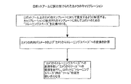
図7を参照すると、対象物の検出および配置を行うための好ましい工程が示されている。まず、ロボットが、対象物を保持する容器もしくはコンテナの上部の所定の位置に配置される。対象物がカメラ視野内に無い場合、ロボットは、画像上でアンカー形状特徴が検出されるまで移動される。次に、アンカー形状特徴の位置および方向を用いて、残りの形状特徴の位置を計算する。画像上においてすべての可視の形状特徴が検出される。画像からの形状特徴の位置およびそれに相応した“オブジェクトスペース”内での位置とともに、カメラキャリブレーションを用いて、“オブジェクトスペース”から“カメラスペース”への変換を計算する。カメラの外部要因的キャリブレーションが上記で参照されているツァイの論文に述べられているように用いられる。
g) The object frame is transmitted to the robot and used as a space for performing operations such as handling.
Referring to FIG. 7, a preferred process for detecting and placing objects is shown. First, the robot is placed at a predetermined position on the top of the container or container that holds the object. If the object is not in the camera field of view, the robot is moved until an anchor shape feature is detected on the image. Next, the positions and directions of the anchor shape features are used to calculate the positions of the remaining shape features. All visible shape features are detected on the image. Along with the position of the shape feature from the image and the corresponding position in the “object space”, the camera calibration is used to calculate the transformation from “object space” to “camera space”. External factorial calibration of the camera is used as described in the Tsai paper referenced above.
次に、前述された変換を用いて、カメラが対象物に対して直交して「見る」ように、すなわち、教示時と同じ位置に、カメラを配置するロボットの動きを計算する。このようにして、教示された形状特徴と可能な限り同じ形状特徴が現れる。これにより、認識および配置の精度はより高まるのである。次に“オブジェクトスペースからカメラスペーズ”間の変換が以前の工程(形状特徴の位置を用いた)と同様な方法で見出される。教示時に記
憶されたオブジェクトフレームは、その見出された変換と“カメラからツール”への変換とを使って計算される。次に、その置換された“オブジェクトフレーム”がロボットに送られる。“ツール”の位置が“ロボットスペース”内でのフレームを定義付けるために使われる。教示されたロボット軌道はこの空間内で実行される。
Next, using the above-described transformation, the motion of the robot that places the camera is calculated so that the camera “sees” perpendicular to the object, that is, at the same position as when teaching. In this way, as much shape features as possible appear as taught. Thereby, the accuracy of recognition and arrangement is further increased. The transformation between “object space to camera space” is then found in a similar way as in the previous step (using the location of the shape features). The object frame stored at the time of teaching is calculated using the found transformation and the “camera to tool” transformation. The replaced “object frame” is then sent to the robot. The “tool” position is used to define the frame in the “robot space”. The taught robot trajectory is executed in this space.
このように、ロボットアームに据え付けられた一つのカメラを用いて、ロボットの教示および3次元上においてロボットによって対象物を取り扱う方法について開示した。この方法においては、対象物の上にある目標点が用いられている。目標は対象物の通常の形状的な特徴である。この方法に準じれば、対象物のCAD設計図を使用する必要はない。また対象物は固定される必要もなく、ロボットの作業スペース内であればどこに置かれていてもよい。この方法は、ひとつの教示された対象物について述べられてきたが、このプロセスを同様な方法で用いて、最初に対象物を認識し、次にその3次元空間での位置を検出してもよい。また、該方法は、対象物のある一つの面上において選択された一連の可視の形状特徴に関して述べられてきたが、該方法は作業状況で現れるあらゆる側面について拡張され得る。 Thus, a method for teaching a robot and handling an object by the robot in three dimensions using a single camera installed on the robot arm has been disclosed. In this method, a target point on the object is used. The goal is a normal geometric feature of the object. According to this method, it is not necessary to use the CAD design drawing of the object. Further, the object does not need to be fixed and may be placed anywhere within the work space of the robot. Although this method has been described for one taught object, this process can be used in a similar manner to first recognize the object and then detect its position in three-dimensional space. Good. Also, although the method has been described with respect to a series of visible shape features selected on one face of an object, the method can be extended for any aspect that appears in a work situation.
上記の方法においては、キャリブレーション工程は、内部およびハンドアイキャリブレーションのみによって実行され得る(つまり、前述の工程i)c)は要さない)。そのような場合、教示工程ii)cにおいて、形状特徴の3次元配置は対象物のCADモデルを使って行われることも可能である。同様に、工程ii)c)において、形状特徴の3次元配置は、いかなるモデルやパーツの計測も要さずに、自動的に計算されることが可能である。 In the above method, the calibration step can be performed only by internal and hand eye calibration (ie, steps i) and c) described above are not required). In such a case, in the teaching step ii) c, the three-dimensional arrangement of the shape features can be performed using a CAD model of the object. Similarly, in steps ii) c), the three-dimensional arrangement of shape features can be automatically calculated without requiring any model or part measurements.
さらに、教示工程ii)i)またはh)は、所期のロボット軌道点の位置をロボットに送ることによって排除することができる。そのような位置は、対象物の現在の位置および方向を用いて計算されている。ロボット軌道点は、オフラインのロボットプログラミングソフトウェアアプリケーションからも得ることが可能である。また、対象物上のひとつもしくはそれ以上の形状特徴が把持ポイントとして用いられ、ロボット座標上でのそれらのポイントの位置がロボットに送信されて、ロボット教示ペンダントを用いたマニュアルでの把持点の教示の必要性が排除されるのである。これに代わって、オブジェクトフレームポイントまたは注目中の他の点(例:ロボット軌道点など)の座標は、ツールからロボットベース間の変換によって変換されることができ、代わりとして、全ての座標はロボットベース座標フレーム内のロボットに送られる。 Further, the teaching steps ii) i) or h) can be eliminated by sending the desired robot trajectory point position to the robot. Such a position is calculated using the current position and orientation of the object. Robot trajectory points can also be obtained from offline robot programming software applications. In addition, one or more shape features on the object are used as grip points, and the positions of those points on the robot coordinates are sent to the robot to teach the grip points manually using the robot teaching pendant. This need is eliminated. Alternatively, the coordinates of object frame points or other points of interest (eg robot trajectory points) can be transformed by conversion from tool to robot base, instead all coordinates are robotic Sent to the robot in the base coordinate frame.
さらに、キャリブレーションおよび教示工程i)およびii)は、グオ−キン ウェイ(Guo-Qing Wei)、クラウス アルブタール(Klaus Arbter)およびゲルト ヒルツィンガー(Gerd Hirzinger)による“Active self-calibration method of robotic eye and hand-eye relationship with model identification ”に述べられているモデル認識によるロボティックアイとハンド−アイの関係のセルフキャリブレーション法を用いて組み合わせることができる。この方法の結果から、カメラの内部パラメータ、ハンドアイキャリブレーションおよびカメラスペース内での選択された形状特徴の位置を得ることができる。残りの軌道教示とランタイムは依然として同様であり、この好ましいアプローチ内にある。 Furthermore, the calibration and teaching steps i) and ii) are described in “Active self-calibration method of robotic eye and hand” by Guo-Qing Wei, Klaus Arbter and Gerd Hirzinger. -eye relationship with model identification "can be combined using the self-calibration method of the robotic eye and hand-eye relationship by model recognition described in" ". From the results of this method, the internal parameters of the camera, hand eye calibration and the position of the selected shape feature in the camera space can be obtained. The remaining trajectory teachings and runtime are still similar and within this preferred approach.
本発明によれば、工程iii−cにおける対象物位置の決定は、以下のアルゴリズムのいずれを用いても行うことができる。
a)前述した論文に記載されている方法から派生する、非線形の最適化法を用いた3次元姿勢の推定:
・Zhengyou Zhangによる“A Flexible New Technique for Camera Calibration (カメラキャリブレーションのためのフレキシブルな新技術)”
・Roger Y. Tsai による“An Efficient and Accurate Camera Calibration Techn
ique for 3D Machine Vision(3D画像装置のための効率的で精度の高いカメラキャリブレーション技術)”;
b)Yucai Liu, Thomas S. Huang, Oliver D. Faugerasによる“Determination of Camera Location from 2D to 3D Line and Point Correspondances(2次元から3次元の線・点一致を判断するカメラロケーション) ”に述べられている線の一致による3次元位置判断;
c)Chien_Ping Lu, Gregory D. Hager, Eric Mjolsness による“Fast and Globally Convergent Pose Estimation from Video Images( 迅速に世界的レベルで収束しつつあるビデオ画像からの位置判断) ”に述べられている“直交的反復(orthogonal iteration)”を用いた位置判断;
d)Thomas Huang, Alfred Bruckenstein, Robert Holt, Arun Netravaliによる“Ununiquness of 3D Pose Under Weak Perspective:A Geometric Proof(悪条件の視野における3次元位置判断の特徴:幾何学的論証) ”で試行された、悪条件視野での近似的対象物位置判断;
e)Chen, Armstrong, Raftopoulosによる“An investigation on the accuracy of three-dimensional space reconstruction using Direct Linear Transformation technique ( 直接一次的置換法を用いた3次元空間再構築の精度に基づく精査) ”に述べられているDLT(直接一次的置換法)を用いたでのおおよその対象物位置判断。
According to the present invention, the object position in step iii-c can be determined using any of the following algorithms.
a) 3D pose estimation using a non-linear optimization method derived from the method described in the paper mentioned above:
・ "A Flexible New Technique for Camera Calibration" by Zhengyou Zhang
・ “An Efficient and Accurate Camera Calibration Techn” by Roger Y. Tsai
ique for 3D Machine Vision (Efficient and accurate camera calibration technology for 3D imaging devices) ";
b) As described in “Determination of Camera Location from 2D to 3D Line and Point Correspondances” by Yucai Liu, Thomas S. Huang, Oliver D. Faugeras 3D position determination based on matching of existing lines;
c) “Orthogonal” as described in “Fast and Globally Convergent Pose Estimation from Video Images” by Chien_Ping Lu, Gregory D. Hager, Eric Mjolsness Position determination using “orthogonal iteration”;
d) Tried in “Ununiquness of 3D Pose Under Weak Perspective: A Geometric Proof” by Thomas Huang, Alfred Bruckenstein, Robert Holt, Arun Netravali. Approximate object position determination in an ill-conditioned field;
e) As described in “An investigation on the accuracy of three-dimensional space reconstruction using Direct Linear Transformation technique” by Chen, Armstrong and Raftopoulos Approximate object position determination using DLT (direct primary replacement method).
ロボッティクス(ロボット工学)における使用に加えて、上記方法は対象物の3次元位置判断の知識が要求される様々な産業及び非産業分野に適用されることができる。
当業者には明らかであるように、前述の開示を鑑みて、本発明の実施においては、本発明の精神および範囲から逸脱することなく、多くの別例および変更がなされ得る。よって、本発明の範囲は、以下の特許請求の範囲によって定義される内容によって解釈されるべきものとする。
In addition to its use in robotics, the method can be applied in various industrial and non-industrial fields where knowledge of 3D position determination of objects is required.
As will be apparent to those skilled in the art, in view of the foregoing disclosure, many alternatives and modifications may be made in the practice of the invention without departing from the spirit and scope of the invention. Accordingly, the scope of the present invention should be construed according to the contents defined by the following claims.
Claims (17)
i)カメラのキャリブレーションを行なう工程であって、
a)カメラ固有のパラメータと、
b)ロボットツールに対するカメラの位置(“ハンド−アイ”キャリブレーション)と、
c)対象物が教示される場所に厳密な空間(“トレーニングスペース”)上でのカメラの位置とを検出することによって行われる工程と、
ii)対象物の形状特徴を教示する工程であって、
a)対象物を“トレーニングスペース”に置き、“カメラからトレーニングスペース”への変換が計算されたキャリブレーションポジションにおいて対象物の画像をロボットによって捕捉することと、
b)捕捉した画像から少なくとも6個の可視の形状特徴を選択することと、
c)“トレーニングスペース”での各々の形状特徴の3次元位置を計算することと、
d)“トレーニングスペース”に整合されているが対象物に関連している“オブジェクトスペース”を定義し、形状特徴の3次元座標を“オブジェクトスペース”に置換することと、
e)“オブジェクトスペース”内の形状特徴の3次元位置と前記画像内の形状特徴の位置を用いて“オブジェクトスペースからカメラ”への変換を計算することと、
f)所期のロボット作業軌道を教示するために使用される“オブジェクトスペース”内の“オブジェクトフレーム”を定義することと、
g)“オブジェクトフレームからカメラ”および“カメラからツール”の変換を用いて、“ツールフレーム”におけるオブジェクトフレームの位置および方向を計算することと、
h)“オブジェクトフレーム”をロボットに送信することと、
i)ロボットを用いて、“オブジェクトフレーム”に関して所期の作業軌道を教示することとによって行なわれる工程と、
iii)対象物の検出および配置を実行する工程であって、
a)ロボットを対象物が収容されている容器容器上の所定位置に配置し、対象物の画像を捕捉することと、
b)その視野内において選択されるべき形状特徴の数が不十分な場合には、少なくとも6個の形状特徴が見つかるまでロボットを移動させることと、
c)画像上の形状特徴の位置およびそれらに相応する教示工程で計算された“オブジェクトスペース”における位置を用いて“オブジェクトスペース”と“カメラスペース”間の変換として対象物の位置を計算することと、
d)その変換を用いて、カメラが対象物に対して直交して見えるようにカメラを配置するためのロボットの動きを計算することと、
e)ロボットを工程d)で計算した位置へ移動することと、
f)工程c)と同様に“オブジェクトスペースからカメラスペース”への変換を求めることと、
g)その求められた変換をと“カメラからツール”への変換とを用いて、教示工程で記憶されたオブジェクトフレームを計算することと、
h)その計算された“オブジェクトフレーム”をロボットに送信することと、
i)“ツール”の位置を用いて、“ロボットスペース”においてそのフレームを定義付け、“ロボットスペース”内の対象物に対して所期の作業軌道を実行することとによって行なわれる工程と、
を含む方法。 A method of handling an object by a robot using a tool and a single camera attached to the robot, the method comprising:
i) a process of calibrating the camera,
a) camera specific parameters;
b) the position of the camera relative to the robot tool ("hand-eye"calibration);
c) detecting the position of the camera on the exact space ("training space") where the object is taught;
ii) teaching the shape features of the object,
a) placing an object in a “training space” and capturing an image of the object by a robot at a calibration position where a conversion from “camera to training space” is calculated;
b) selecting at least six visible shape features from the captured image;
c) calculating the three-dimensional position of each shape feature in the “training space”;
d) defining an “object space” that is aligned with the “training space” but related to the object, and replacing the three-dimensional coordinates of the shape feature with the “object space”;
e) calculating the transformation from “object space to camera” using the three-dimensional position of the shape feature in the “object space” and the position of the shape feature in the image;
f) defining an “object frame” within an “object space” used to teach the intended robot work trajectory;
g) calculating the position and orientation of the object frame in the “tool frame” using the “object frame to camera” and “camera to tool” transformations;
h) sending an “object frame” to the robot;
i) using a robot to teach the intended work trajectory with respect to the “object frame”;
iii) performing the detection and placement of the object,
a) placing the robot in a predetermined position on the container that contains the object, capturing an image of the object;
b) if the number of shape features to be selected in the field of view is insufficient, moving the robot until at least 6 shape features are found;
c) calculating the position of the object as a transformation between "object space" and "camera space" using the positions of the shape features on the image and their corresponding positions in the "object space" calculated in the teaching process. When,
d) using the transformation to calculate the movement of the robot to position the camera so that the camera appears orthogonal to the object;
e) moving the robot to the position calculated in step d);
f) obtaining a conversion from “object space to camera space” as in step c);
g) calculating the object frame stored in the teaching process using the determined conversion and the “camera to tool” conversion;
h) sending the calculated “object frame” to the robot;
i) using the position of the “tool” to define its frame in the “robot space” and performing the intended work trajectory on the object in the “robot space”;
Including methods.
i)カメラのキャリブレーションを行なう工程であって、
a)カメラ固有のパラメータと、
b)ロボットツールに対するカメラの位置(“ハンド−アイ”キャリブレーション)とを検出することによって行なわれる工程と、
ii)対象物の形状特徴を教示する工程であって、
a)対象物をカメラの視野内におき、該対象物の画像を捕捉することと、
b)捕捉した画像から少なくとも6個の可視の形状特徴を選択することと、
c)対象物と関係するスペース(“オブジェクトスペース”)内の選択された形状特徴の現実座標における3次元位置を計算することと、
d)このスペースの形状特徴の3次元位置と画像上の位置とを用いて、“オブジェクトスペースからカメラ”の変換を計算することと、
e)ハンドリング軌道を教示するために使われる“オブジェクトスペース”内の“オブジェクトフレーム”を定義付けることと、
f)“オブジェクトフレームからカメラ”および“カメラからツール”の変換を用いて、“ツールフレーム”内の“オブジェクトフレーム”の位置と方向を計算することと、
g)その計算された“オブジェクトフレーム”をロボットに送信することと、
h)“オブジェクトフレーム”内での所期の作業軌道を教示することとによって行なわれる工程と、
iii)対象物の検出および配置を行なう工程であって、
a)ロボットを対象物が入っている容器容器上の所定位置に配置することと、
b)前記視野内において選択されるべき形状特徴の数が不十分な場合には、少なくとも6個の形状特徴が見つかるまでロボットを移動させることと、
c)前記画像からの形状特徴の位置およびそれらに相応する教示工程で計算された“オブジェクトスペース”における位置を用いて、“オブジェクトスペース”と“カメラスペース”間の変換として対象物の位置を計算することと、
d)その変換を用い、カメラが対象物に対して直交して見えるようにカメラを配置するためのロボットの動きを計算することと、
e)工程d)と同様に“オブジェクトスペースからカメラスペース”への変換を求めることと、
f)その求められた変換および“カメラからツール”への変換を用いて、教示工程で記憶されたオブジェクトフレームを計算することと、
g)その計算された“オブジェクトフレーム”をロボットに送信することと、
h)“ツール”の位置を用いて“ロボットスペース”におけるそのフレームを定義付け、“ロボットスペース”内の対象物に対する所期の作業軌道を実行することとによって行なわれる工程と、
を含む方法。 A method of handling an object by a robot using a tool attached to the robot and a single camera, the method comprising:
i) a process of calibrating the camera,
a) camera specific parameters;
b) a step performed by detecting the position of the camera relative to the robot tool ("hand-eye"calibration);
ii) teaching the shape features of the object,
a) placing the object in the field of view of the camera and capturing an image of the object;
b) selecting at least six visible shape features from the captured image;
c) calculating a three-dimensional position in real coordinates of a selected shape feature in a space related to the object (“object space”);
d) using the 3D position of the shape feature of this space and the position on the image to calculate the transformation from “object space to camera”;
e) defining an “object frame” in the “object space” used to teach the handling trajectory;
f) using the “object frame to camera” and “camera to tool” transformations to calculate the position and orientation of the “object frame” within the “tool frame”;
g) sending the calculated “object frame” to the robot;
h) a process performed by teaching the intended work trajectory within the “object frame”;
iii) detecting and arranging the object,
a) placing the robot in place on the container containing the object;
b) if the number of shape features to be selected in the field of view is insufficient, moving the robot until at least 6 shape features are found;
c) Using the position of the shape feature from the image and the corresponding position in the “object space” calculated in the teaching process, calculate the position of the object as a conversion between “object space” and “camera space” To do
d) using the transformation to calculate the movement of the robot to position the camera so that the camera appears orthogonal to the object;
e) as in step d), seeking conversion from “object space to camera space”;
f) using the determined transformation and the “camera to tool” transformation to calculate the object frame stored in the teaching step;
g) sending the calculated “object frame” to the robot;
h) using the position of the “tool” to define its frame in the “robot space” and performing the intended work trajectory for the object in the “robot space”;
Including methods.
i)以下の論文に詳述されている方法から派生する、非線形の最大効率法を用いた3次元姿勢の推定であって、前記論文が、
・Zhengyou Zhangによる“A Flexible New Technique for Camera Calibration (カメラキャリブレーションのためのフレキシブルな新技術)”および
・Roger Y. Tsai による“An Efficient and Accurate Camera Calibration Technique for 3D Machine Vision(3D画像装置のための効率的で精度の高いカメラキャリブレーション技術)”である、3次元姿勢の推定と、
ii)Yucai Liu, Thomas S. Huang, Oliver D. Faugerasによる“Determination of Camera Location from 2D to 3D Line and Point Correspondances(2次元から3次元の線・点一致を判断するカメラロケーション)”に述べられている、選択された形状特徴がエッジ(縁)である場合における線の一致による3次元姿勢の推定と、
iii)Chien_Ping Lu, Gregory D. Hager, Eric Mjolsness による“Fast and Globally Convergent Pose Estimation from Video Images( 迅速に世界的レベルで収束しつつあるビデオ画像からの位置方向判断) ”に述べられている“直交的反復(orthogonal iteration)”を用いた姿勢の推定と、
iv)Thomas Huang, Alfred Bruckenstein, Robert Holt, Arun Netravaliによる“Ununiquness of 3D Pose Under Weak Perspective:A Geometric Proof(悪条件の視野における3次元位置方向判断の特徴:幾何学的) ”で試行された、悪条件視野での近似的対象物位置判断と、
v)Chen, Armstrong, Raftopoulosによる“An investigation on the accuracy of three-dimensional space reconstruction using Direct Linear Transformation technique (直接一次的置換法を用いた3次元空間再構築の精度に基づく精査)”に述べられているDLT(直接一次的置換法)を用いた近似的対象物位置判断とのうちのいずれかである、方法。 The method according to claim 1, wherein the determination of the object position in step iii d) is performed by using an algorithm, the algorithm comprising:
i) 3-D pose estimation using a non-linear maximum efficiency method derived from the method detailed in the following paper,
・ "A Flexible New Technique for Camera Calibration" by Zhengyou Zhang and "An Efficient and Accurate Camera Calibration Technique for 3D Machine Vision" by Roger Y. Tsai Efficient and highly accurate camera calibration technology) ”,
ii) As described in “Determination of Camera Location from 2D to 3D Line and Point Correspondances” by Yucai Liu, Thomas S. Huang, Oliver D. Faugeras 3D pose estimation by line matching when the selected shape feature is an edge,
iii) “Orthogonal” as described in “Fast and Globally Convergent Pose Estimation from Video Images” by Chien_Ping Lu, Gregory D. Hager, Eric Mjolsness Pose estimation using “orthogonal iteration”;
iv) “Ununiquness of 3D Pose Under Weak Perspective: A Geometric Proof” by Thomas Huang, Alfred Bruckenstein, Robert Holt, Arun Netravali Approximate object position determination in an ill-conditioned field
v) As described in “An investigation on the accuracy of three-dimensional space reconstruction using Direct Linear Transformation technique” by Chen, Armstrong, Raftopoulos A method that is one of approximate object position determination using DLT (Direct Primary Replacement Method).
i)以下の論文に詳述されている方法から派生する、非線形の最大効率法を用いた3次元姿勢の推定であって、前記論文が、
・Zhengyou Zhangによる“A Flexible New Technique for Camera Calibration (カメラキャリブレーションのためのフレキシブルな新技術)”および
・Roger Y. Tsai による“An Efficient and Accurate Camera Calibration Technique for 3D Machine Vision(3D画像装置のための効率的で精度の高いカメラキャリブレーション技術)”である、3次元姿勢の推定と、
ii)Yucai Liu, Thomas S. Huang, Oliver D. Faugerasによる“Determination of Camera Location from 2D to 3D Line and Point Correspondances (2次元から3次元の線・点一致を判断するカメラロケーション)”に述べられている、選択された形状特徴がエッジ(縁)の場合における線の一致による3次元姿勢の推定と、
iii)Chien_Ping Lu, Gregory D. Hager, Eric Mjolsness による“Fast and Globally Convergent Pose Estimation from Video Images( 迅速に世界的レベルで収束しつつあるビデオ画像からの位置方向判断) ”に述べられている“直交的反復(orthogonal iteration)”を用いた姿勢の推定と、
iv)Thomas Huang, Alfred Bruckenstein, Robert Holt, Arun Netravaliによる“Ununiquness of 3D Pose Under Weak Perspective:A Geometric Proof(悪条件の視野における3次元位置方向判断の特徴:幾何学的) ”で試行された、悪条件視野での近似的対象物位置判断と、
v)Chen, Armstrong, Raftopoulosによる“An investigation on the accuracy of three-dimensional space reconstruction using Direct Linear Transformation technique (直接一次的置換法を用いた3次元空間再構築の精度に基づく精査)”に述べられているDLT(直接一次的置換法)を用いた近似的対象物位置判断とのうちのいずれかである、方法。 The method according to claim 2, wherein the determination of the object position in step iii d) is performed by using an algorithm, the algorithm comprising:
i) 3-D pose estimation using a non-linear maximum efficiency method derived from the method detailed in the following paper,
・ "A Flexible New Technique for Camera Calibration" by Zhengyou Zhang and "An Efficient and Accurate Camera Calibration Technique for 3D Machine Vision" by Roger Y. Tsai Efficient and highly accurate camera calibration technology) ”,
ii) As described in “Determination of Camera Location from 2D to 3D Line and Point Correspondances” by Yucai Liu, Thomas S. Huang, Oliver D. Faugeras Estimating a three-dimensional pose by matching lines when the selected shape feature is an edge;
iii) “Orthogonal” as described in “Fast and Globally Convergent Pose Estimation from Video Images” by Chien_Ping Lu, Gregory D. Hager, Eric Mjolsness Pose estimation using “orthogonal iteration”;
iv) “Ununiquness of 3D Pose Under Weak Perspective: A Geometric Proof” by Thomas Huang, Alfred Bruckenstein, Robert Holt, Arun Netravali Approximate object position determination in an ill-conditioned field,
v) As described in “An investigation on the accuracy of three-dimensional space reconstruction using Direct Linear Transformation technique” by Chen, Armstrong, Raftopoulos A method that is one of approximate object position determination using DLT (Direct Primary Replacement Method).
Applications Claiming Priority (3)
| Application Number | Priority Date | Filing Date | Title |
|---|---|---|---|
| CA002369845A CA2369845A1 (en) | 2002-01-31 | 2002-01-31 | Method and apparatus for single camera 3d vision guided robotics |
| US10/153,680 US6816755B2 (en) | 2002-01-31 | 2002-05-24 | Method and apparatus for single camera 3D vision guided robotics |
| PCT/CA2003/000139 WO2003064116A2 (en) | 2002-01-31 | 2003-01-31 | Method and apparatus for single camera 3d vision guided robotics |
Publications (2)
| Publication Number | Publication Date |
|---|---|
| JP2005515910A true JP2005515910A (en) | 2005-06-02 |
| JP2005515910A5 JP2005515910A5 (en) | 2006-03-16 |
Family
ID=31189178
Family Applications (1)
| Application Number | Title | Priority Date | Filing Date |
|---|---|---|---|
| JP2003563782A Pending JP2005515910A (en) | 2002-01-31 | 2003-01-31 | Method and apparatus for single camera 3D vision guide robotics |
Country Status (5)
| Country | Link |
|---|---|
| US (1) | US8095237B2 (en) |
| EP (1) | EP1472052A2 (en) |
| JP (1) | JP2005515910A (en) |
| AU (1) | AU2003239171A1 (en) |
| WO (1) | WO2003064116A2 (en) |
Cited By (5)
| Publication number | Priority date | Publication date | Assignee | Title |
|---|---|---|---|---|
| JP2009279677A (en) * | 2008-05-20 | 2009-12-03 | Fanuc Ltd | Robot control apparatus which carries out position teaching of robot using measuring device |
| JP2012517053A (en) * | 2009-02-03 | 2012-07-26 | ファナック ロボティクス アメリカ コーポレイション | Robot tool control method |
| CN103459102A (en) * | 2011-03-24 | 2013-12-18 | 佳能株式会社 | Robot control apparatus, robot control method, program, and recording medium |
| JP2015118101A (en) * | 2015-02-02 | 2015-06-25 | キヤノン株式会社 | Information processing device and method and program |
| US11872702B2 (en) * | 2018-09-13 | 2024-01-16 | The Charles Stark Draper Laboratory, Inc. | Robot interaction with human co-workers |
Families Citing this family (159)
| Publication number | Priority date | Publication date | Assignee | Title |
|---|---|---|---|---|
| EP1472052A2 (en) | 2002-01-31 | 2004-11-03 | Braintech Canada, Inc. | Method and apparatus for single camera 3d vision guided robotics |
| DE10305384A1 (en) * | 2003-02-11 | 2004-08-26 | Kuka Roboter Gmbh | Method and device for visualizing computer-aided information |
| JP4167954B2 (en) | 2003-09-02 | 2008-10-22 | ファナック株式会社 | Robot and robot moving method |
| DE10345743A1 (en) | 2003-10-01 | 2005-05-04 | Kuka Roboter Gmbh | Method and device for determining the position and orientation of an image receiving device |
| EP1675709A2 (en) * | 2003-10-20 | 2006-07-05 | Isra Vision Systems AG | Method for effecting the movement of a handling device and image processing device |
| JP3905073B2 (en) * | 2003-10-31 | 2007-04-18 | ファナック株式会社 | Arc welding robot |
| JP3733364B2 (en) * | 2003-11-18 | 2006-01-11 | ファナック株式会社 | Teaching position correction method |
| FI123306B (en) * | 2004-01-30 | 2013-02-15 | Wisematic Oy | Robot tool system and procedure for its control, computer software and software product |
| US7336814B2 (en) * | 2004-07-14 | 2008-02-26 | Braintech Canada, Inc. | Method and apparatus for machine-vision |
| JP2006289531A (en) * | 2005-04-07 | 2006-10-26 | Seiko Epson Corp | Movement control device for robot position teaching, robot position teaching device, movement control method for robot position teaching, robot position teaching method, and movement control program for robot position teaching |
| KR20080009745A (en) * | 2005-07-15 | 2008-01-29 | 가부시키가이샤 야스카와덴키 | Wafer Position Teaching Method and Teaching Fixture Device |
| EP1924400B1 (en) * | 2005-09-13 | 2012-03-21 | Gudmunn Slettemoen | Opto-mechanical position finder |
| US20070073439A1 (en) * | 2005-09-23 | 2007-03-29 | Babak Habibi | System and method of visual tracking |
| DE102005045854B3 (en) * | 2005-09-26 | 2007-04-12 | Siemens Ag | Method and system for calibrating a camera in production machines |
| US20070276539A1 (en) * | 2006-05-25 | 2007-11-29 | Babak Habibi | System and method of robotically engaging an object |
| US8560047B2 (en) | 2006-06-16 | 2013-10-15 | Board Of Regents Of The University Of Nebraska | Method and apparatus for computer aided surgery |
| US8437535B2 (en) * | 2006-09-19 | 2013-05-07 | Roboticvisiontech Llc | System and method of determining object pose |
| GB2444738A (en) * | 2006-12-12 | 2008-06-18 | Prosurgics Ltd | Registration of the location of a workpiece within the frame of reference of a device |
| WO2008076942A1 (en) * | 2006-12-15 | 2008-06-26 | Braintech Canada, Inc. | System and method of identifying objects |
| NO327279B1 (en) * | 2007-05-22 | 2009-06-02 | Metaio Gmbh | Camera position estimation device and method for augmented reality imaging |
| DE102007030378A1 (en) * | 2007-06-29 | 2009-01-02 | Spatial View Gmbh Dresden | Camera system e.g. eye tracking system, position determining method for use in vehicle, involves performing determination of position of camera system with respect to reference system under consideration of position of display system |
| US7957583B2 (en) * | 2007-08-02 | 2011-06-07 | Roboticvisiontech Llc | System and method of three-dimensional pose estimation |
| WO2009045390A1 (en) * | 2007-10-01 | 2009-04-09 | Kaufman Engineered System | Vision aided case/bulk palletizer system |
| JP5448326B2 (en) * | 2007-10-29 | 2014-03-19 | キヤノン株式会社 | Gripping device and gripping device control method |
| DE102007060653A1 (en) * | 2007-12-15 | 2009-06-18 | Abb Ag | Position determination of an object |
| EP2075096A1 (en) * | 2007-12-27 | 2009-07-01 | Leica Geosystems AG | Method and system for extremely precise positioning of at least one object in the end position of a space |
| JP4347386B2 (en) * | 2008-01-23 | 2009-10-21 | ファナック株式会社 | Processing robot program creation device |
| JP5039950B2 (en) * | 2008-03-21 | 2012-10-03 | インターナショナル・ビジネス・マシーンズ・コーポレーション | Object movement control system, object movement control method, server, and computer program |
| EP2271465A1 (en) * | 2008-03-31 | 2011-01-12 | Abb Research | Robot parts assembly on a workpiece moving on an assembly line |
| DE102008002642A1 (en) * | 2008-06-25 | 2010-02-25 | Kuka Roboter Gmbh | Robot and method for attaching a tool to a robot |
| US8559699B2 (en) | 2008-10-10 | 2013-10-15 | Roboticvisiontech Llc | Methods and apparatus to facilitate operations in image based systems |
| JP2011000703A (en) | 2009-05-19 | 2011-01-06 | Canon Inc | Manipulator with camera |
| US8310539B2 (en) * | 2009-05-29 | 2012-11-13 | Mori Seiki Co., Ltd | Calibration method and calibration device |
| DE102009041734B4 (en) * | 2009-09-16 | 2023-11-02 | Kuka Roboter Gmbh | Measuring a manipulator |
| US8941726B2 (en) * | 2009-12-10 | 2015-01-27 | Mitsubishi Electric Research Laboratories, Inc. | Method and system for segmenting moving objects from images using foreground extraction |
| JP5665333B2 (en) * | 2010-03-10 | 2015-02-04 | キヤノン株式会社 | Information processing apparatus and information processing apparatus control method |
| US9393694B2 (en) | 2010-05-14 | 2016-07-19 | Cognex Corporation | System and method for robust calibration between a machine vision system and a robot |
| JP5505138B2 (en) * | 2010-07-05 | 2014-05-28 | 株式会社安川電機 | Robot apparatus and gripping method using robot apparatus |
| KR101813922B1 (en) * | 2010-07-12 | 2018-01-02 | 엘지전자 주식회사 | Robot cleaner and controlling method of the same |
| KR101677634B1 (en) * | 2010-07-12 | 2016-11-18 | 엘지전자 주식회사 | Robot cleaner and controlling method of the same |
| DE202010008191U1 (en) * | 2010-07-30 | 2010-11-04 | Walter Maschinenbau Gmbh | Device for teaching a gripping device |
| EP2453325A1 (en) * | 2010-11-16 | 2012-05-16 | Universal Robots ApS | Method and means for controlling a robot |
| US9124873B2 (en) | 2010-12-08 | 2015-09-01 | Cognex Corporation | System and method for finding correspondence between cameras in a three-dimensional vision system |
| US8600192B2 (en) * | 2010-12-08 | 2013-12-03 | Cognex Corporation | System and method for finding correspondence between cameras in a three-dimensional vision system |
| JP2012206219A (en) * | 2011-03-30 | 2012-10-25 | Seiko Epson Corp | Robot control device and robot system |
| US20120290130A1 (en) * | 2011-05-10 | 2012-11-15 | Agile Planet, Inc. | Method to Model and Program a Robotic Workcell |
| US9026242B2 (en) * | 2011-05-19 | 2015-05-05 | Taktia Llc | Automatically guided tools |
| KR101951414B1 (en) * | 2011-06-22 | 2019-02-22 | 엘지전자 주식회사 | Robot cleaner and controlling method of the same |
| EP2723270B1 (en) | 2011-06-27 | 2019-01-23 | Board of Regents of the University of Nebraska | On-board tool tracking system of computer assisted surgery |
| US11911117B2 (en) | 2011-06-27 | 2024-02-27 | Board Of Regents Of The University Of Nebraska | On-board tool tracking system and methods of computer assisted surgery |
| US9498231B2 (en) | 2011-06-27 | 2016-11-22 | Board Of Regents Of The University Of Nebraska | On-board tool tracking system and methods of computer assisted surgery |
| WO2013023130A1 (en) * | 2011-08-11 | 2013-02-14 | Siemens Healthcare Diagnostics Inc. | Methods and apparatus to calibrate an orientation between a robot gripper and a camera |
| EP2760642B1 (en) | 2011-09-28 | 2015-11-18 | Universal Robots A/S | Calibration and programming of robots |
| DE102011084353B4 (en) * | 2011-10-12 | 2015-05-07 | Trumpf Laser- Und Systemtechnik Gmbh | Method and computer program for setting up a gripper robot, as well as gripper robot |
| US9451810B2 (en) * | 2011-11-18 | 2016-09-27 | Nike, Inc. | Automated identification of shoe parts |
| US8958901B2 (en) | 2011-11-18 | 2015-02-17 | Nike, Inc. | Automated manufacturing of shoe parts |
| US8755925B2 (en) | 2011-11-18 | 2014-06-17 | Nike, Inc. | Automated identification and assembly of shoe parts |
| US10552551B2 (en) | 2011-11-18 | 2020-02-04 | Nike, Inc. | Generation of tool paths for shore assembly |
| US8849620B2 (en) | 2011-11-18 | 2014-09-30 | Nike, Inc. | Automated 3-D modeling of shoe parts |
| JP2013184257A (en) | 2012-03-08 | 2013-09-19 | Sony Corp | Robot apparatus, method for controlling robot apparatus, and computer program |
| EP3964902B1 (en) | 2012-04-26 | 2024-01-03 | Shaper Tools, Inc. | Systems and methods for performing a task on a material, or locating the position of a device relative to the surface of the material |
| US9280037B2 (en) | 2012-05-03 | 2016-03-08 | Serview, Inc. | Machine vision camera mount with rotational adjustment |
| US8965576B2 (en) | 2012-06-21 | 2015-02-24 | Rethink Robotics, Inc. | User interfaces for robot training |
| JP5642738B2 (en) * | 2012-07-26 | 2014-12-17 | ファナック株式会社 | Apparatus and method for picking up loosely stacked articles by robot |
| JP5469216B2 (en) * | 2012-07-31 | 2014-04-16 | ファナック株式会社 | A device for picking up bulk items by robot |
| JP6195333B2 (en) * | 2012-08-08 | 2017-09-13 | キヤノン株式会社 | Robot equipment |
| US9008757B2 (en) | 2012-09-26 | 2015-04-14 | Stryker Corporation | Navigation system including optical and non-optical sensors |
| EP2926543B1 (en) * | 2012-11-29 | 2017-11-22 | Csir | A method of calibrating a camera and a system therefor |
| EP3459468B1 (en) | 2013-03-13 | 2020-07-15 | Stryker Corporation | Method and system for arranging objects in an operating room |
| JP5768827B2 (en) * | 2013-03-14 | 2015-08-26 | 株式会社安川電機 | Robot system and workpiece transfer method |
| US10105149B2 (en) | 2013-03-15 | 2018-10-23 | Board Of Regents Of The University Of Nebraska | On-board tool tracking system and methods of computer assisted surgery |
| US20140327746A1 (en) * | 2013-05-06 | 2014-11-06 | Iphoton Solutions, Llc | Volume reconstruction of an object using a 3d sensor and robotic coordinates |
| ES2522921B2 (en) | 2013-05-17 | 2015-07-30 | Loxin 2002, S.L. | Head and automatic machining procedure with vision |
| KR101459479B1 (en) * | 2013-07-01 | 2014-11-07 | 현대자동차 주식회사 | All in one jigless projection loading system and vehicle parts assembly method with the same |
| US9245916B2 (en) | 2013-07-09 | 2016-01-26 | Rememdia LC | Optical positioning sensor |
| CN104298244B (en) * | 2013-07-17 | 2016-12-28 | 刘永 | A kind of localization method of industrial robot three-dimensional real-time high-precision positioner |
| DE102013017895B4 (en) * | 2013-10-29 | 2018-06-28 | Rwth Aachen | Method for continuously determining the 3D positions and trajectory of the movement of a dynamic manufacturing object |
| JP5815761B2 (en) * | 2014-01-23 | 2015-11-17 | ファナック株式会社 | Visual sensor data creation system and detection simulation system |
| US9452531B2 (en) | 2014-02-04 | 2016-09-27 | Microsoft Technology Licensing, Llc | Controlling a robot in the presence of a moving object |
| US10399232B2 (en) | 2014-03-04 | 2019-09-03 | Universal Robots A/S | Safety system for industrial robot |
| JP6364836B2 (en) * | 2014-03-14 | 2018-08-01 | セイコーエプソン株式会社 | Robot, robot system, and control device |
| DE102014004919B4 (en) * | 2014-04-07 | 2022-05-12 | Abb Schweiz Ag | Method and means for manipulating an object |
| US9579799B2 (en) * | 2014-04-30 | 2017-02-28 | Coleman P. Parker | Robotic control system using virtual reality input |
| JP5778311B1 (en) * | 2014-05-08 | 2015-09-16 | 東芝機械株式会社 | Picking apparatus and picking method |
| JP6357949B2 (en) * | 2014-07-29 | 2018-07-18 | セイコーエプソン株式会社 | Control system, robot system, and control method |
| CN106715058A (en) | 2014-09-26 | 2017-05-24 | 泰拉丁公司 | Grasping gripper |
| US9193073B1 (en) * | 2014-10-15 | 2015-11-24 | Quanta Storage Inc. | Robot calibration apparatus for calibrating a robot arm |
| CN105522576A (en) * | 2014-10-27 | 2016-04-27 | 广明光电股份有限公司 | Method for automatic recalibration of robotic arm |
| DE102014223167A1 (en) * | 2014-11-13 | 2016-05-19 | Kuka Roboter Gmbh | Determining object-related gripping spaces by means of a robot |
| US9561587B2 (en) * | 2014-12-16 | 2017-02-07 | Amazon Technologies, Inc. | Robotic grasping of items in inventory system |
| US9857786B2 (en) * | 2015-03-31 | 2018-01-02 | Recognition Robotics, Inc. | System and method for aligning a coordinated movement machine reference frame with a measurement system reference frame |
| US9851196B2 (en) | 2015-04-17 | 2017-12-26 | Rememdia LC | Sensor |
| US10456883B2 (en) | 2015-05-13 | 2019-10-29 | Shaper Tools, Inc. | Systems, methods and apparatus for guided tools |
| JP2016221645A (en) * | 2015-06-02 | 2016-12-28 | セイコーエプソン株式会社 | Robot, robot control device and robot system |
| DE102015008188B3 (en) * | 2015-06-25 | 2016-06-16 | Kuka Roboter Gmbh | Departure of a predetermined path with a robot |
| EP3112965A1 (en) * | 2015-07-02 | 2017-01-04 | Accenture Global Services Limited | Robotic process automation |
| WO2017005272A1 (en) | 2015-07-08 | 2017-01-12 | Universal Robots A/S | Method for extending end user programming of an industrial robot with third party contributions |
| US20170032529A1 (en) * | 2015-07-27 | 2017-02-02 | Csir | Method of calibrating a helmet and a system therefor |
| DE102015216659A1 (en) * | 2015-09-01 | 2017-03-02 | Siemens Aktiengesellschaft | Device for connection to a robot |
| US20180290297A1 (en) * | 2015-10-02 | 2018-10-11 | Verselus, Llc | System and method for autonomously teaching working points in a robotic disk test apparatus |
| US11054802B2 (en) * | 2015-10-21 | 2021-07-06 | Mitsubishi Electric Research Laboratories, Inc. | System and method for performing operations of numerical control machines |
| WO2017075277A1 (en) * | 2015-10-30 | 2017-05-04 | Seurat Technologies, Inc. | Part manipulation using printed manipulation points |
| WO2017087986A1 (en) * | 2015-11-20 | 2017-05-26 | The Regents On The University Of California | Non-anthropomorphic bipedal robotic system |
| US9757859B1 (en) * | 2016-01-21 | 2017-09-12 | X Development Llc | Tooltip stabilization |
| US9744665B1 (en) | 2016-01-27 | 2017-08-29 | X Development Llc | Optimization of observer robot locations |
| US10059003B1 (en) | 2016-01-28 | 2018-08-28 | X Development Llc | Multi-resolution localization system |
| JP6333871B2 (en) * | 2016-02-25 | 2018-05-30 | ファナック株式会社 | Image processing apparatus for displaying an object detected from an input image |
| US10452071B1 (en) | 2016-02-29 | 2019-10-22 | AI Incorporated | Obstacle recognition method for autonomous robots |
| TWI805545B (en) | 2016-04-12 | 2023-06-21 | 丹麥商環球機器人公司 | Method and computer program product for programming a robot by demonstration |
| US9987747B2 (en) * | 2016-05-24 | 2018-06-05 | Semes Co., Ltd. | Stocker for receiving cassettes and method of teaching a stocker robot disposed therein |
| JP6500852B2 (en) * | 2016-07-11 | 2019-04-17 | 株式会社安川電機 | Robot system, robot control method, robot controller |
| JP6553552B2 (en) * | 2016-07-25 | 2019-07-31 | ファナック株式会社 | Numerical controller with function to automate measurement operation using camera |
| RU2748005C2 (en) | 2016-08-19 | 2021-05-18 | Шапер Тулс, Инк. | Systems, methods and device for sharing tool manufacturing and design data |
| US9805306B1 (en) | 2016-11-23 | 2017-10-31 | Accenture Global Solutions Limited | Cognitive robotics analyzer |
| CN110402190B (en) * | 2017-03-23 | 2022-12-06 | 株式会社富士 | Robot system |
| JP2018167334A (en) * | 2017-03-29 | 2018-11-01 | セイコーエプソン株式会社 | Teaching device and teaching method |
| TWI658345B (en) * | 2017-04-05 | 2019-05-01 | Southern Taiwan University Of Science And Technology | Modular machine control device based on image correction |
| US10919152B1 (en) | 2017-05-30 | 2021-02-16 | Nimble Robotics, Inc. | Teleoperating of robots with tasks by mapping to human operator pose |
| US20180348730A1 (en) * | 2017-06-01 | 2018-12-06 | X Development Llc | Automatic Generation of Toolpaths |
| US10235192B2 (en) | 2017-06-23 | 2019-03-19 | Accenture Global Solutions Limited | Self-learning robotic process automation |
| US11370111B2 (en) * | 2017-09-20 | 2022-06-28 | Magna International Inc. | System and method for adaptive bin picking for manufacturing |
| JP2019058993A (en) * | 2017-09-27 | 2019-04-18 | セイコーエプソン株式会社 | Robot system |
| US11358290B2 (en) * | 2017-10-19 | 2022-06-14 | Canon Kabushiki Kaisha | Control apparatus, robot system, method for operating control apparatus, and storage medium |
| CN108247635B (en) * | 2018-01-15 | 2021-03-26 | 北京化工大学 | A method of deep vision robot grasping objects |
| JP6888580B2 (en) * | 2018-04-05 | 2021-06-16 | オムロン株式会社 | Information processing equipment, information processing methods, and programs |
| CN108549322B (en) * | 2018-04-11 | 2019-07-02 | 广州启帆工业机器人有限公司 | Pose synchronization method and device for arc track motion of robot |
| US11287507B2 (en) | 2018-04-30 | 2022-03-29 | The Boeing Company | System and method for testing a structure using laser ultrasound |
| US11040452B2 (en) * | 2018-05-29 | 2021-06-22 | Abb Schweiz Ag | Depth sensing robotic hand-eye camera using structured light |
| US11407111B2 (en) | 2018-06-27 | 2022-08-09 | Abb Schweiz Ag | Method and system to generate a 3D model for a robot scene |
| EP3587044B1 (en) * | 2018-06-28 | 2021-05-19 | Sick Ag | Method for gripping objects in a search area and positioning system |
| CN109238135B (en) * | 2018-07-30 | 2020-08-18 | 珠海市运泰利自动化设备有限公司 | Method for accurately positioning incoming material to test box based on vision |
| CN111070199A (en) * | 2018-10-18 | 2020-04-28 | 杭州海康威视数字技术股份有限公司 | Hand-eye calibration assessment method and robot |
| WO2020082176A1 (en) * | 2018-10-23 | 2020-04-30 | Waste Robotics Inc. | Robotic spearing device for performing item capture and sorting, spearing end effector and method for performing same |
| US10926416B2 (en) * | 2018-11-21 | 2021-02-23 | Ford Global Technologies, Llc | Robotic manipulation using an independently actuated vision system, an adversarial control scheme, and a multi-tasking deep learning architecture |
| JP6904327B2 (en) * | 2018-11-30 | 2021-07-14 | オムロン株式会社 | Control device, control method, and control program |
| US20200202178A1 (en) * | 2018-12-19 | 2020-06-25 | Abb Schweiz Ag | Automatic visual data generation for object training and evaluation |
| RU2713570C1 (en) * | 2018-12-20 | 2020-02-05 | Анатолий Александрович Перепелица | Method for generating augmented reality image and robotic system for its implementation |
| US11911914B2 (en) | 2019-01-28 | 2024-02-27 | Cognex Corporation | System and method for automatic hand-eye calibration of vision system for robot motion |
| US12082898B2 (en) | 2019-02-06 | 2024-09-10 | Covidien Lp | Hand eye coordination system for robotic surgical system |
| DE102019106458A1 (en) * | 2019-03-13 | 2020-09-17 | ese-robotics GmbH | Method for controlling an industrial robot |
| WO2020192882A1 (en) * | 2019-03-25 | 2020-10-01 | Abb Schweiz Ag | Method and control arrangement for determining a relation between a robot coordinate system and a movable apparatus coordinate system |
| US11584013B2 (en) * | 2020-03-31 | 2023-02-21 | Wipro Limited | System, device and method for determining error in robotic manipulator-to-camera calibration |
| CN112066876B (en) * | 2020-08-27 | 2021-07-02 | 武汉大学 | A method of quickly measuring the size of an object using a mobile phone |
| US12162074B2 (en) | 2020-11-25 | 2024-12-10 | Lawrence Livermore National Security, Llc | System and method for large-area pulsed laser melting of metallic powder in a laser powder bed fusion application |
| US20220219328A1 (en) * | 2021-01-08 | 2022-07-14 | General Electric Company | Method and device for creation of three dimensional tool frame |
| US11832909B2 (en) | 2021-03-31 | 2023-12-05 | Moon Surgical Sas | Co-manipulation surgical system having actuatable setup joints |
| US12178418B2 (en) | 2021-03-31 | 2024-12-31 | Moon Surgical Sas | Co-manipulation surgical system having a coupling mechanism removeably attachable to surgical instruments |
| US11844583B2 (en) | 2021-03-31 | 2023-12-19 | Moon Surgical Sas | Co-manipulation surgical system having an instrument centering mode for automatic scope movements |
| US11819302B2 (en) | 2021-03-31 | 2023-11-21 | Moon Surgical Sas | Co-manipulation surgical system having user guided stage control |
| US12042241B2 (en) | 2021-03-31 | 2024-07-23 | Moon Surgical Sas | Co-manipulation surgical system having automated preset robot arm configurations |
| US11812938B2 (en) | 2021-03-31 | 2023-11-14 | Moon Surgical Sas | Co-manipulation surgical system having a coupling mechanism removeably attachable to surgical instruments |
| EP4312857A1 (en) | 2021-03-31 | 2024-02-07 | Moon Surgical SAS | Co-manipulation surgical system for use with surgical instruments for performing laparoscopic surgery |
| US12167900B2 (en) | 2021-03-31 | 2024-12-17 | Moon Surgical Sas | Co-manipulation surgical system having automated preset robot arm configurations |
| US12019050B2 (en) | 2021-04-07 | 2024-06-25 | The Boeing Company | Ultrasound inspection system and method |
| DE102021203779B4 (en) | 2021-04-16 | 2023-12-14 | Volkswagen Aktiengesellschaft | Method and device for annotating images of an object recorded with the aid of a camera |
| US11911915B2 (en) * | 2021-06-09 | 2024-02-27 | Intrinsic Innovation Llc | Determining robotic calibration processes |
| CA3230374A1 (en) * | 2021-08-29 | 2023-03-09 | Quartus Engineering Incorporated | Methods and systems of generating camera models for camera calibration |
| US11986165B1 (en) | 2023-01-09 | 2024-05-21 | Moon Surgical Sas | Co-manipulation surgical system for use with surgical instruments for performing laparoscopic surgery while estimating hold force |
| US11839442B1 (en) | 2023-01-09 | 2023-12-12 | Moon Surgical Sas | Co-manipulation surgical system for use with surgical instruments for performing laparoscopic surgery while estimating hold force |
Family Cites Families (131)
| Publication number | Priority date | Publication date | Assignee | Title |
|---|---|---|---|---|
| US3986007A (en) * | 1975-08-20 | 1976-10-12 | The Bendix Corporation | Method and apparatus for calibrating mechanical-visual part manipulating system |
| US4011437A (en) * | 1975-09-12 | 1977-03-08 | Cincinnati Milacron, Inc. | Method and apparatus for compensating for unprogrammed changes in relative position between a machine and workpiece |
| US4146924A (en) * | 1975-09-22 | 1979-03-27 | Board Of Regents For Education Of The State Of Rhode Island | System for visually determining position in space and/or orientation in space and apparatus employing same |
| CA1121888A (en) * | 1977-04-30 | 1982-04-13 | Junichi Ikeda | Industrial robot |
| CA1103803A (en) * | 1978-03-01 | 1981-06-23 | National Research Council Of Canada | Method and apparatus of determining the center of area or centroid of a geometrical area of unspecified shape lying in a larger x-y scan field |
| JPS5923467B2 (en) * | 1979-04-16 | 1984-06-02 | 株式会社日立製作所 | Position detection method |
| US4373804A (en) | 1979-04-30 | 1983-02-15 | Diffracto Ltd. | Method and apparatus for electro-optically determining the dimension, location and attitude of objects |
| US4305130A (en) * | 1979-05-29 | 1981-12-08 | University Of Rhode Island | Apparatus and method to enable a robot with vision to acquire, orient and transport workpieces |
| US4294544A (en) * | 1979-08-03 | 1981-10-13 | Altschuler Bruce R | Topographic comparator |
| US4402053A (en) | 1980-09-25 | 1983-08-30 | Board Of Regents For Education For The State Of Rhode Island | Estimating workpiece pose using the feature points method |
| US6317953B1 (en) * | 1981-05-11 | 2001-11-20 | Lmi-Diffracto | Vision target based assembly |
| US4654949A (en) * | 1982-02-16 | 1987-04-07 | Diffracto Ltd. | Method for automatically handling, assembling and working on objects |
| US5506682A (en) * | 1982-02-16 | 1996-04-09 | Sensor Adaptive Machines Inc. | Robot vision using targets |
| US4613942A (en) * | 1982-02-19 | 1986-09-23 | Chen Richard M | Orientation and control system for robots |
| US4437114A (en) * | 1982-06-07 | 1984-03-13 | Farrand Optical Co., Inc. | Robotic vision system |
| EP0114505B1 (en) | 1982-12-28 | 1987-05-13 | Diffracto Ltd. | Apparatus and method for robot calibration |
| US4523809A (en) * | 1983-08-04 | 1985-06-18 | The United States Of America As Represented By The Secretary Of The Air Force | Method and apparatus for generating a structured light beam array |
| EP0151417A1 (en) * | 1984-01-19 | 1985-08-14 | Hitachi, Ltd. | Method for correcting systems of coordinates in a robot having visual sensor device and apparatus therefor |
| US4578561A (en) * | 1984-08-16 | 1986-03-25 | General Electric Company | Method of enhancing weld pool boundary definition |
| US5267143A (en) * | 1984-10-12 | 1993-11-30 | Sensor Adaptive Machines, Incorporated | Vision assisted fixture construction |
| US4687325A (en) * | 1985-03-28 | 1987-08-18 | General Electric Company | Three-dimensional range camera |
| US4879664A (en) * | 1985-05-23 | 1989-11-07 | Kabushiki Kaisha Toshiba | Three-dimensional position sensor and three-dimensional position setting system |
| US4871252A (en) * | 1986-10-30 | 1989-10-03 | The Regents Of The University Of California | Method and apparatus for object positioning |
| US4791482A (en) | 1987-02-06 | 1988-12-13 | Westinghouse Electric Corp. | Object locating system |
| JPS63288683A (en) * | 1987-05-21 | 1988-11-25 | 株式会社東芝 | Assembling robot |
| US4942539A (en) * | 1988-12-21 | 1990-07-17 | Gmf Robotics Corporation | Method and system for automatically determining the position and orientation of an object in 3-D space |
| JP2710850B2 (en) * | 1989-03-27 | 1998-02-10 | キヤノン株式会社 | Work holding device, work and its storage case |
| US4985846A (en) * | 1989-05-11 | 1991-01-15 | Fallon Patrick J | Acoustical/optical bin picking system |
| JP2509357B2 (en) * | 1990-01-19 | 1996-06-19 | トキコ株式会社 | Work position detector |
| JP2899075B2 (en) * | 1990-06-29 | 1999-06-02 | 三菱電機株式会社 | Synchronous drive device and synchronous drive method |
| JP2686351B2 (en) * | 1990-07-19 | 1997-12-08 | ファナック株式会社 | Vision sensor calibration method |
| US5208763A (en) * | 1990-09-14 | 1993-05-04 | New York University | Method and apparatus for determining position and orientation of mechanical objects |
| US5083073A (en) * | 1990-09-20 | 1992-01-21 | Mazada Motor Manufacturing U.S.A. Corp. | Method and apparatus for calibrating a vision guided robot |
| US5325468A (en) * | 1990-10-31 | 1994-06-28 | Sanyo Electric Co., Ltd. | Operation planning system for robot |
| US5212738A (en) | 1991-04-12 | 1993-05-18 | Martin Marietta Magnesia Specialties Inc. | Scanning laser measurement system |
| GB2261069B (en) * | 1991-10-30 | 1995-11-01 | Nippon Denso Co | High speed picking system for stacked parts |
| JP2767340B2 (en) * | 1991-12-26 | 1998-06-18 | ファナック株式会社 | 3D position / posture measurement method for objects |
| IT1258006B (en) * | 1992-01-13 | 1996-02-20 | Gd Spa | SYSTEM AND METHOD FOR THE AUTOMATIC COLLECTION OF OBJECTS |
| US5715166A (en) * | 1992-03-02 | 1998-02-03 | General Motors Corporation | Apparatus for the registration of three-dimensional shapes |
| US5300869A (en) * | 1992-07-30 | 1994-04-05 | Iowa State University Research Foundation, Inc. | Nonholonomic camera space manipulation |
| US5745523A (en) * | 1992-10-27 | 1998-04-28 | Ericsson Inc. | Multi-mode signal processing |
| US5499306A (en) * | 1993-03-08 | 1996-03-12 | Nippondenso Co., Ltd. | Position-and-attitude recognition method and apparatus by use of image pickup means |
| FR2706345B1 (en) * | 1993-06-11 | 1995-09-22 | Bertin & Cie | Method and device for locating in space a mobile object such as a sensor or a tool carried by a robot. |
| US5625576A (en) * | 1993-10-01 | 1997-04-29 | Massachusetts Institute Of Technology | Force reflecting haptic interface |
| US5568593A (en) * | 1994-01-13 | 1996-10-22 | Ethicon, Inc. | Robotic control system for a needle sorting and feeding apparatus |
| JP3394322B2 (en) | 1994-05-19 | 2003-04-07 | ファナック株式会社 | Coordinate system setting method using visual sensor |
| US5454775A (en) * | 1994-09-13 | 1995-10-03 | Applied Robotics, Inc. | Automated exchangeable parts feeding system |
| US6560349B1 (en) * | 1994-10-21 | 2003-05-06 | Digimarc Corporation | Audio monitoring using steganographic information |
| CA2172791C (en) | 1995-03-31 | 2000-11-14 | Teruyoshi Washizawa | Method and apparatus for processing visual information |
| DE19515949C2 (en) | 1995-05-02 | 1999-02-04 | Continental Ag | Method and device for areal measurement and detection of the tread wear of a vehicle tire |
| US5633676A (en) * | 1995-08-22 | 1997-05-27 | E. L. Harley Inc. | Apparatus and method for mounting printing plates and proofing |
| DE59507847D1 (en) | 1995-09-15 | 2000-03-30 | Ersue Enis | Method for determining the position of a body in space |
| JP3413694B2 (en) * | 1995-10-17 | 2003-06-03 | ソニー株式会社 | Robot control method and robot |
| US5802201A (en) * | 1996-02-09 | 1998-09-01 | The Trustees Of Columbia University In The City Of New York | Robot system with vision apparatus and transparent grippers |
| US5809006A (en) * | 1996-05-31 | 1998-09-15 | Cagent Technologies, Inc. | Optical disk with copy protection, and apparatus and method for recording and reproducing same |
| JP2001525074A (en) * | 1996-06-03 | 2001-12-04 | ライカ ミクロスコピー ズュステーメ アーゲー | Moving object position detection |
| US6004016A (en) | 1996-08-06 | 1999-12-21 | Trw Inc. | Motion planning and control for systems with multiple mobile objects |
| WO1998017444A1 (en) * | 1996-10-24 | 1998-04-30 | Fanuc Ltd | Force control robot system with visual sensor for inserting work |
| US6064759A (en) * | 1996-11-08 | 2000-05-16 | Buckley; B. Shawn | Computer aided inspection machine |
| US6463358B1 (en) * | 1996-11-26 | 2002-10-08 | Fanuc Ltd. | Robot control device having operation route simulation function |
| US5974169A (en) * | 1997-03-20 | 1999-10-26 | Cognex Corporation | Machine vision methods for determining characteristics of an object using boundary points and bounding regions |
| US5978521A (en) | 1997-09-25 | 1999-11-02 | Cognex Corporation | Machine vision methods using feedback to determine calibration locations of multiple cameras that image a common object |
| EP0911603B1 (en) | 1997-10-22 | 2001-06-27 | ISRA Vision Systems AG | Method for the determination of the position of a three-dimensional body |
| FR2770317B1 (en) * | 1997-10-24 | 2000-12-08 | Commissariat Energie Atomique | METHOD FOR CALIBRATING THE ORIGINAL POSITION AND ORIENTATION OF ONE OR MORE MOBILE CAMERAS AND ITS APPLICATION TO MEASURING THE THREE-DIMENSIONAL POSITION OF FIXED OBJECTS |
| US6278890B1 (en) * | 1998-11-09 | 2001-08-21 | Medacoustics, Inc. | Non-invasive turbulent blood flow imaging system |
| JPH11300670A (en) * | 1998-04-21 | 1999-11-02 | Fanuc Ltd | Article picking-up device |
| US6549288B1 (en) * | 1998-05-14 | 2003-04-15 | Viewpoint Corp. | Structured-light, triangulation-based three-dimensional digitizer |
| US6516092B1 (en) * | 1998-05-29 | 2003-02-04 | Cognex Corporation | Robust sub-model shape-finder |
| JP4387476B2 (en) | 1998-07-13 | 2009-12-16 | 株式会社明電舎 | Bin picking position data calibration device |
| US7036094B1 (en) * | 1998-08-10 | 2006-04-25 | Cybernet Systems Corporation | Behavior recognition system |
| US6628819B1 (en) | 1998-10-09 | 2003-09-30 | Ricoh Company, Ltd. | Estimation of 3-dimensional shape from image sequence |
| US5959425A (en) * | 1998-10-15 | 1999-09-28 | Fanuc Robotics North America, Inc. | Vision guided automatic robotic path teaching method |
| DE19855478B4 (en) * | 1998-12-01 | 2006-01-12 | Steinbichler Optotechnik Gmbh | Method and device for optical detection of a contrast line |
| AU3350400A (en) * | 1999-01-29 | 2000-08-18 | Georgia Tech Research Corporation | Uncalibrated dynamic mechanical system controller |
| JP4794708B2 (en) * | 1999-02-04 | 2011-10-19 | オリンパス株式会社 | 3D position and orientation sensing device |
| WO2000057129A1 (en) * | 1999-03-19 | 2000-09-28 | Matsushita Electric Works, Ltd. | Three-dimensional object recognition method and pin picking system using the method |
| US6341246B1 (en) * | 1999-03-26 | 2002-01-22 | Kuka Development Laboratories, Inc. | Object oriented motion system |
| JP3300682B2 (en) * | 1999-04-08 | 2002-07-08 | ファナック株式会社 | Robot device with image processing function |
| JP3421608B2 (en) | 1999-04-08 | 2003-06-30 | ファナック株式会社 | Teaching model generator |
| JP3377465B2 (en) * | 1999-04-08 | 2003-02-17 | ファナック株式会社 | Image processing device |
| US6961628B2 (en) * | 1999-04-16 | 2005-11-01 | Siemens Energy & Automation, Inc. | Method and apparatus for tuning compensation parameters |
| KR100314748B1 (en) * | 1999-05-03 | 2001-11-23 | 양재신 | A numerical control device and method for displaying three dimensional graphics in real time |
| US6415051B1 (en) * | 1999-06-24 | 2002-07-02 | Geometrix, Inc. | Generating 3-D models using a manually operated structured light source |
| US6490369B1 (en) | 1999-07-06 | 2002-12-03 | Fanuc Robotics North America | Method of viewing and identifying a part for a robot manipulator |
| CA2277855A1 (en) | 1999-07-14 | 2001-01-14 | Solvision | Method and system of measuring the height of weld beads in a printed circuit |
| US7006236B2 (en) * | 2002-05-22 | 2006-02-28 | Canesta, Inc. | Method and apparatus for approximating depth of an object's placement onto a monitored region with applications to virtual interface devices |
| EP1236018A1 (en) * | 1999-11-12 | 2002-09-04 | Go Sensors, L.L.C. | Robust landmarks for machine vision and methods for detecting same |
| US20010055069A1 (en) * | 2000-03-10 | 2001-12-27 | Hudson Edison T. | One camera system for component to substrate registration |
| US6748104B1 (en) * | 2000-03-24 | 2004-06-08 | Cognex Corporation | Methods and apparatus for machine vision inspection using single and multiple templates or patterns |
| EP1195231A4 (en) * | 2000-03-31 | 2006-01-25 | Sony Corp | Robot device, robot device action control method, external force detecting device and external force detecting method |
| US7084868B2 (en) * | 2000-04-26 | 2006-08-01 | University Of Louisville Research Foundation, Inc. | System and method for 3-D digital reconstruction of an oral cavity from a sequence of 2-D images |
| JP4265088B2 (en) | 2000-07-10 | 2009-05-20 | 株式会社豊田中央研究所 | Robot apparatus and control method thereof |
| JP2002025958A (en) * | 2000-07-13 | 2002-01-25 | Canon Inc | Method and apparatus for precision grinding of semiconductor substrate |
| EP1172183A3 (en) | 2000-07-13 | 2006-01-04 | Rolf Kleck | Device and arrangement for generating corrected motion data for predefined motion of a mobile installation, mobile installation and system comprising mobile installations |
| US6392744B1 (en) * | 2000-12-11 | 2002-05-21 | Analog Technologies, Corp. | Range measurement system |
| US6804416B1 (en) * | 2001-03-16 | 2004-10-12 | Cognex Corporation | Method and system for aligning geometric object models with images |
| US6792140B2 (en) * | 2001-04-26 | 2004-09-14 | Mitsubish Electric Research Laboratories, Inc. | Image-based 3D digitizer |
| US7362969B2 (en) * | 2001-05-29 | 2008-04-22 | Lucent Technologies Inc. | Camera model and calibration procedure for omnidirectional paraboloidal catadioptric cameras |
| BE1014222A3 (en) * | 2001-06-13 | 2003-06-03 | Ct Rech Metallurgiques Asbl | Characterization ONLINE PROCESS OF MOVING SURFACE AND DEVICE FOR ITS IMPLEMENTATION. |
| US6507773B2 (en) * | 2001-06-14 | 2003-01-14 | Sharper Image Corporation | Multi-functional robot with remote and video system |
| US7061628B2 (en) | 2001-06-27 | 2006-06-13 | Southwest Research Institute | Non-contact apparatus and method for measuring surface profile |
| US6466843B1 (en) * | 2001-10-16 | 2002-10-15 | General Electric Company | Method and apparatus for lifting objects |
| US6580971B2 (en) * | 2001-11-13 | 2003-06-17 | Thierica, Inc. | Multipoint inspection system |
| EP1472052A2 (en) | 2002-01-31 | 2004-11-03 | Braintech Canada, Inc. | Method and apparatus for single camera 3d vision guided robotics |
| CA2369845A1 (en) * | 2002-01-31 | 2003-07-31 | Braintech, Inc. | Method and apparatus for single camera 3d vision guided robotics |
| DE10235905A1 (en) | 2002-03-04 | 2003-09-18 | Vmt Bildverarbeitungssysteme G | Method of determining spatial position of an object and a workpiece for automatically mounting the workpiece on the object, involves robot holding the workpiece over object and cameras establishing coordinates of reference object |
| US6917702B2 (en) * | 2002-04-24 | 2005-07-12 | Mitsubishi Electric Research Labs, Inc. | Calibration of multiple cameras for a turntable-based 3D scanner |
| KR100956537B1 (en) * | 2002-04-26 | 2010-05-07 | 혼다 기켄 고교 가부시키가이샤 | Magnetic Posture Estimator for Legged Mobile Robot |
| DE10236040A1 (en) | 2002-08-06 | 2004-02-19 | Manz Automation Ag | Gripper or handling device for picking up an object and moving it from one location to another comprises an array of cameras linked to an evaluation and control unit for determination of the object position relative to the gripper |
| US7009717B2 (en) * | 2002-08-14 | 2006-03-07 | Metris N.V. | Optical probe for scanning the features of an object and methods therefor |
| JP3702257B2 (en) | 2002-08-23 | 2005-10-05 | ファナック株式会社 | Robot handling device |
| JP4004899B2 (en) * | 2002-09-02 | 2007-11-07 | ファナック株式会社 | Article position / orientation detection apparatus and article removal apparatus |
| US7277599B2 (en) * | 2002-09-23 | 2007-10-02 | Regents Of The University Of Minnesota | System and method for three-dimensional video imaging using a single camera |
| US6871115B2 (en) * | 2002-10-11 | 2005-03-22 | Taiwan Semiconductor Manufacturing Co., Ltd | Method and apparatus for monitoring the operation of a wafer handling robot |
| JP3859571B2 (en) * | 2002-10-17 | 2006-12-20 | ファナック株式会社 | 3D visual sensor |
| JP3711105B2 (en) * | 2002-12-20 | 2005-10-26 | ファナック株式会社 | 3D measuring device |
| SE525108C2 (en) * | 2002-12-30 | 2004-11-30 | Abb Research Ltd | Method and system for programming an industrial robot, computer program product, computer-readable medium and use |
| DE10319253B4 (en) | 2003-04-28 | 2005-05-19 | Tropf, Hermann | Three-dimensionally accurate feeding with robots |
| JP3834297B2 (en) * | 2003-05-12 | 2006-10-18 | ファナック株式会社 | Image processing device |
| EP1484716A1 (en) | 2003-06-06 | 2004-12-08 | Sony France S.A. | An architecture for self-developing devices |
| US6836702B1 (en) | 2003-06-11 | 2004-12-28 | Abb Ab | Method for fine tuning of a robot program |
| US20050097021A1 (en) * | 2003-11-03 | 2005-05-05 | Martin Behr | Object analysis apparatus |
| US7693325B2 (en) * | 2004-01-14 | 2010-04-06 | Hexagon Metrology, Inc. | Transprojection of geometry data |
| US8542219B2 (en) | 2004-01-30 | 2013-09-24 | Electronic Scripting Products, Inc. | Processing pose data derived from the pose of an elongate object |
| JP2005291824A (en) * | 2004-03-31 | 2005-10-20 | Yokohama National Univ | Flying object flight behavior measuring device and flying object flight behavior measuring method |
| JP2005313280A (en) * | 2004-04-28 | 2005-11-10 | Fanuc Ltd | Numerical control device |
| DE102004026814A1 (en) | 2004-06-02 | 2005-12-29 | Kuka Roboter Gmbh | Method and device for improving the positioning accuracy of a handling device |
| US7336814B2 (en) * | 2004-07-14 | 2008-02-26 | Braintech Canada, Inc. | Method and apparatus for machine-vision |
| US7069090B2 (en) * | 2004-08-02 | 2006-06-27 | E.G.O. North America, Inc. | Systems and methods for providing variable output feedback to a user of a household appliance |
| US7233389B2 (en) * | 2004-12-03 | 2007-06-19 | Omnitek Partners, Llc | System and method for the measurement of the velocity and acceleration of objects |
| US20070073439A1 (en) * | 2005-09-23 | 2007-03-29 | Babak Habibi | System and method of visual tracking |
-
2003
- 2003-01-31 EP EP03734637A patent/EP1472052A2/en not_active Withdrawn
- 2003-01-31 WO PCT/CA2003/000139 patent/WO2003064116A2/en active Application Filing
- 2003-01-31 AU AU2003239171A patent/AU2003239171A1/en not_active Abandoned
- 2003-01-31 JP JP2003563782A patent/JP2005515910A/en active Pending
- 2003-08-06 US US10/634,874 patent/US8095237B2/en not_active Expired - Lifetime
Cited By (7)
| Publication number | Priority date | Publication date | Assignee | Title |
|---|---|---|---|---|
| JP2009279677A (en) * | 2008-05-20 | 2009-12-03 | Fanuc Ltd | Robot control apparatus which carries out position teaching of robot using measuring device |
| JP2012517053A (en) * | 2009-02-03 | 2012-07-26 | ファナック ロボティクス アメリカ コーポレイション | Robot tool control method |
| CN103459102A (en) * | 2011-03-24 | 2013-12-18 | 佳能株式会社 | Robot control apparatus, robot control method, program, and recording medium |
| US8977395B2 (en) | 2011-03-24 | 2015-03-10 | Canon Kabushiki Kaisha | Robot control apparatus, robot control method, program, and recording medium |
| JP2015118101A (en) * | 2015-02-02 | 2015-06-25 | キヤノン株式会社 | Information processing device and method and program |
| US11872702B2 (en) * | 2018-09-13 | 2024-01-16 | The Charles Stark Draper Laboratory, Inc. | Robot interaction with human co-workers |
| US20240227189A1 (en) * | 2018-09-13 | 2024-07-11 | Dexai Robotics, Inc. | Robot Interaction With Human Co-Workers |
Also Published As
| Publication number | Publication date |
|---|---|
| US8095237B2 (en) | 2012-01-10 |
| AU2003239171A1 (en) | 2003-09-02 |
| US20040172164A1 (en) | 2004-09-02 |
| WO2003064116A3 (en) | 2004-02-05 |
| WO2003064116A2 (en) | 2003-08-07 |
| EP1472052A2 (en) | 2004-11-03 |
Similar Documents
| Publication | Publication Date | Title |
|---|---|---|
| JP2005515910A (en) | Method and apparatus for single camera 3D vision guide robotics | |
| US6816755B2 (en) | Method and apparatus for single camera 3D vision guided robotics | |
| JP7292829B2 (en) | Systems and methods for combining machine vision coordinate spaces in a guided assembly environment | |
| JP6021533B2 (en) | Information processing system, apparatus, method, and program | |
| JP6966582B2 (en) | Systems and methods for automatic hand-eye calibration of vision systems for robot motion | |
| CN109373898B (en) | A system and method for pose estimation of complex parts based on 3D measurement point cloud | |
| JP6855492B2 (en) | Robot system, robot system control device, and robot system control method | |
| JP6000579B2 (en) | Information processing apparatus and information processing method | |
| JP6180087B2 (en) | Information processing apparatus and information processing method | |
| JP5854815B2 (en) | Information processing apparatus, information processing apparatus control method, and program | |
| US20200298411A1 (en) | Method for the orientation of an industrial robot, and industrial robot | |
| US7280687B2 (en) | Device for detecting position/orientation of object | |
| JP5815761B2 (en) | Visual sensor data creation system and detection simulation system | |
| JP6324025B2 (en) | Information processing apparatus and information processing method | |
| EP3577629B1 (en) | Calibration article for a 3d vision robotic system | |
| JP6855491B2 (en) | Robot system, robot system control device, and robot system control method | |
| JP2016099257A (en) | Information processing device and information processing method | |
| US12073582B2 (en) | Method and apparatus for determining a three-dimensional position and pose of a fiducial marker | |
| JP2016170050A (en) | Position attitude measurement device, position attitude measurement method and computer program | |
| JP6885856B2 (en) | Robot system and calibration method | |
| CN111390910A (en) | Manipulator target grabbing and positioning method, computer readable storage medium and manipulator | |
| US12036663B2 (en) | Method and control arrangement for determining a relation between a robot coordinate system and a movable apparatus coordinate system | |
| Heikkilä et al. | Calibration procedures for object locating sensors in flexible robotized machining | |
| CN118322213A (en) | Vision-based kinematic calibration method for industrial robots in large workspaces | |
| JP2021079507A (en) | Marker and robot system |
Legal Events
| Date | Code | Title | Description |
|---|---|---|---|
| A521 | Written amendment |
Free format text: JAPANESE INTERMEDIATE CODE: A523 Effective date: 20060130 |
|
| A621 | Written request for application examination |
Free format text: JAPANESE INTERMEDIATE CODE: A621 Effective date: 20060130 |
|
| A977 | Report on retrieval |
Free format text: JAPANESE INTERMEDIATE CODE: A971007 Effective date: 20080118 |
|
| A131 | Notification of reasons for refusal |
Free format text: JAPANESE INTERMEDIATE CODE: A131 Effective date: 20080129 |
|
| A601 | Written request for extension of time |
Free format text: JAPANESE INTERMEDIATE CODE: A601 Effective date: 20080430 |
|
| A602 | Written permission of extension of time |
Free format text: JAPANESE INTERMEDIATE CODE: A602 Effective date: 20080509 |
|
| A521 | Written amendment |
Free format text: JAPANESE INTERMEDIATE CODE: A523 Effective date: 20080729 |
|
| A02 | Decision of refusal |
Free format text: JAPANESE INTERMEDIATE CODE: A02 Effective date: 20090120 |