JP2005503210A - Microstructure for delivering compositions to the skin through the skin using a rotatable structure - Google Patents
Microstructure for delivering compositions to the skin through the skin using a rotatable structure Download PDFInfo
- Publication number
- JP2005503210A JP2005503210A JP2003528611A JP2003528611A JP2005503210A JP 2005503210 A JP2005503210 A JP 2005503210A JP 2003528611 A JP2003528611 A JP 2003528611A JP 2003528611 A JP2003528611 A JP 2003528611A JP 2005503210 A JP2005503210 A JP 2005503210A
- Authority
- JP
- Japan
- Prior art keywords
- skin
- microelements
- substrate
- microelement
- microstructure
- Prior art date
- Legal status (The legal status is an assumption and is not a legal conclusion. Google has not performed a legal analysis and makes no representation as to the accuracy of the status listed.)
- Pending
Links
Images


Classifications
-
- A—HUMAN NECESSITIES
- A61—MEDICAL OR VETERINARY SCIENCE; HYGIENE
- A61M—DEVICES FOR INTRODUCING MEDIA INTO, OR ONTO, THE BODY; DEVICES FOR TRANSDUCING BODY MEDIA OR FOR TAKING MEDIA FROM THE BODY; DEVICES FOR PRODUCING OR ENDING SLEEP OR STUPOR
- A61M37/00—Other apparatus for introducing media into the body; Percutany, i.e. introducing medicines into the body by diffusion through the skin
- A61M37/0015—Other apparatus for introducing media into the body; Percutany, i.e. introducing medicines into the body by diffusion through the skin by using microneedles
-
- A—HUMAN NECESSITIES
- A61—MEDICAL OR VETERINARY SCIENCE; HYGIENE
- A61B—DIAGNOSIS; SURGERY; IDENTIFICATION
- A61B17/00—Surgical instruments, devices or methods
- A61B17/20—Surgical instruments, devices or methods for vaccinating or cleaning the skin previous to the vaccination
- A61B17/205—Vaccinating by means of needles or other puncturing devices
-
- A—HUMAN NECESSITIES
- A61—MEDICAL OR VETERINARY SCIENCE; HYGIENE
- A61B—DIAGNOSIS; SURGERY; IDENTIFICATION
- A61B17/00—Surgical instruments, devices or methods
- A61B17/32—Surgical cutting instruments
- A61B17/322—Skin grafting apparatus
-
- A—HUMAN NECESSITIES
- A61—MEDICAL OR VETERINARY SCIENCE; HYGIENE
- A61B—DIAGNOSIS; SURGERY; IDENTIFICATION
- A61B17/00—Surgical instruments, devices or methods
- A61B2017/00743—Type of operation; Specification of treatment sites
- A61B2017/00747—Dermatology
- A61B2017/00761—Removing layer of skin tissue, e.g. wrinkles, scars or cancerous tissue
-
- A—HUMAN NECESSITIES
- A61—MEDICAL OR VETERINARY SCIENCE; HYGIENE
- A61B—DIAGNOSIS; SURGERY; IDENTIFICATION
- A61B17/00—Surgical instruments, devices or methods
- A61B2017/00743—Type of operation; Specification of treatment sites
- A61B2017/00747—Dermatology
- A61B2017/00765—Decreasing the barrier function of skin tissue by radiated energy, e.g. using ultrasound, using laser for skin perforation
-
- A—HUMAN NECESSITIES
- A61—MEDICAL OR VETERINARY SCIENCE; HYGIENE
- A61B—DIAGNOSIS; SURGERY; IDENTIFICATION
- A61B17/00—Surgical instruments, devices or methods
- A61B17/32—Surgical cutting instruments
- A61B2017/320004—Surgical cutting instruments abrasive
- A61B2017/320008—Scrapers
-
- A—HUMAN NECESSITIES
- A61—MEDICAL OR VETERINARY SCIENCE; HYGIENE
- A61M—DEVICES FOR INTRODUCING MEDIA INTO, OR ONTO, THE BODY; DEVICES FOR TRANSDUCING BODY MEDIA OR FOR TAKING MEDIA FROM THE BODY; DEVICES FOR PRODUCING OR ENDING SLEEP OR STUPOR
- A61M37/00—Other apparatus for introducing media into the body; Percutany, i.e. introducing medicines into the body by diffusion through the skin
- A61M37/0015—Other apparatus for introducing media into the body; Percutany, i.e. introducing medicines into the body by diffusion through the skin by using microneedles
- A61M2037/0023—Drug applicators using microneedles
-
- A—HUMAN NECESSITIES
- A61—MEDICAL OR VETERINARY SCIENCE; HYGIENE
- A61M—DEVICES FOR INTRODUCING MEDIA INTO, OR ONTO, THE BODY; DEVICES FOR TRANSDUCING BODY MEDIA OR FOR TAKING MEDIA FROM THE BODY; DEVICES FOR PRODUCING OR ENDING SLEEP OR STUPOR
- A61M37/00—Other apparatus for introducing media into the body; Percutany, i.e. introducing medicines into the body by diffusion through the skin
- A61M37/0015—Other apparatus for introducing media into the body; Percutany, i.e. introducing medicines into the body by diffusion through the skin by using microneedles
- A61M2037/003—Other apparatus for introducing media into the body; Percutany, i.e. introducing medicines into the body by diffusion through the skin by using microneedles having a lumen
-
- A—HUMAN NECESSITIES
- A61—MEDICAL OR VETERINARY SCIENCE; HYGIENE
- A61M—DEVICES FOR INTRODUCING MEDIA INTO, OR ONTO, THE BODY; DEVICES FOR TRANSDUCING BODY MEDIA OR FOR TAKING MEDIA FROM THE BODY; DEVICES FOR PRODUCING OR ENDING SLEEP OR STUPOR
- A61M37/00—Other apparatus for introducing media into the body; Percutany, i.e. introducing medicines into the body by diffusion through the skin
- A61M37/0015—Other apparatus for introducing media into the body; Percutany, i.e. introducing medicines into the body by diffusion through the skin by using microneedles
- A61M2037/0038—Other apparatus for introducing media into the body; Percutany, i.e. introducing medicines into the body by diffusion through the skin by using microneedles having a channel at the side surface
Landscapes
- Health & Medical Sciences (AREA)
- Life Sciences & Earth Sciences (AREA)
- Engineering & Computer Science (AREA)
- Surgery (AREA)
- General Health & Medical Sciences (AREA)
- Biomedical Technology (AREA)
- Heart & Thoracic Surgery (AREA)
- Medical Informatics (AREA)
- Animal Behavior & Ethology (AREA)
- Public Health (AREA)
- Veterinary Medicine (AREA)
- Molecular Biology (AREA)
- Nuclear Medicine, Radiotherapy & Molecular Imaging (AREA)
- Dermatology (AREA)
- Anesthesiology (AREA)
- Hematology (AREA)
- Plastic & Reconstructive Surgery (AREA)
- Transplantation (AREA)
- Medicinal Preparation (AREA)
- Surgical Instruments (AREA)
- Media Introduction/Drainage Providing Device (AREA)
Abstract
出血又は組織の損傷もたらさず、及び痛み又はその他の外傷がなく、皮膚の角質層を介して、組成物、好ましくは医療用組成物若しくは薬剤組成物又は活性成分を送達するシステムとして、改善された方法及び装置が提供される。微細要素の寸法及び形状は、皮膚への貫通の深さを制御するために制御される。組成物が、チャンバーから微細要素を通って皮膚の中に流れることができる連絡路が作られるように、微細要素は「中空」であり得る。あるいは、微細要素は「中空でない」こともでき、組成物は、微細要素を皮膚の表面に適用して角質層に開口部を作る直前又は直後に、皮膚に直接適用される。もう1つの別の実施形態は、回転可能に皮膚に適用され角質層全体を貫通する円筒形微細構造を用い;及びこれは種々の異なる構造により流体を分配することができる。Improved as a system for delivering a composition, preferably a medical or pharmaceutical composition or active ingredient, through the stratum corneum of the skin without causing bleeding or tissue damage and without pain or other trauma Methods and apparatus are provided. The dimensions and shape of the microelements are controlled to control the depth of penetration into the skin. The microelements can be “hollow” so that a communication path is created through which the composition can flow from the chamber through the microelements and into the skin. Alternatively, the microelements can be “non-hollow” and the composition is applied directly to the skin immediately before or after applying the microelements to the surface of the skin to create an opening in the stratum corneum. Another alternative embodiment uses a cylindrical microstructure that is rotatably applied to the skin and penetrates the entire stratum corneum; and it can distribute fluid by a variety of different structures.
Description
【技術分野】
【0001】
本発明は、一般に皮膚の中に組成物を送達するシステムに関するものであり、特に、皮膚を介して(又は皮下に)組成物を皮膚の中に送達するのに用いられる製品を指向する。本発明は、具体的には、皮膚の表面を切開し、組成物を有効に適用することができる深さまで皮膚の表面を貫通することが可能である平面配列の微細要素として開示される。製品は、それに取り付けられた容器から組成物を送達できるか、又は組成物を直接皮膚に適用し、製品と組み合わせてその中で利用することができる。
【背景技術】
【0002】
ヒトの皮膚は最大の器官である。皮膚温を調整する機能は別として、皮膚の最も重要な機能は、毒性物質、微生物のような異物による、また機械的損傷による身体への傷害に対して有効なバリアとして役立つことである。ヒトの皮膚は数層を備えており、最外層は角質層であり、それは死んだ皮膚細胞を備え、身体の最初の保護バリアの実質的な部分を構成している。ほとんどの皮膚は角質層を含み、それは厚さが15〜20層の死んだ細胞である(厚さ約10〜20ミクロン)。しかしながら、かかと又はたこのような「丈夫な」皮膚層の一部は、厚さ100〜150ミクロンの角質層を含み得る。平均して、皮膚は毎日、少なくとも1層の皮膚が自然に落ち、1層から4層までの皮膚は、皮膚の保護的性質や健康に影響を与えることなく取り除いてもよい。実際、角質層の4層までを取り除くことによって、メークアップが更に均一に施され、いったん施されると更に美的に見栄えする外観を有する皮膚の表面領域がもたらされ得る。
【0003】
医薬組成物を送達するために皮膚の外層を貫通させることは広く行われている。通常、医薬品の注入は、皮下送達、筋肉内送達、並びに静脈内送達によって作用する。あまり侵襲的でない手順が今や開発されており、広く利用されている。中でも「局所的な」適用はパッチであり、飛行機酔い及び乗り物酔い組成物、又は喫煙軽減組成物のような組成物の緩慢な放出を提供するのに用いられる。しかしながら、これらのパッチデリバリーシステムは、皮膚バリアを横切って血流に有効成分を運ぶことができる処方に依存している。従って、処方及び服用の制限が、パッチを介して薬物又は皮膚利益組成物を送達するのを妨害する可能性がある。
【0004】
従って、皮膚を介して(又は皮下に)組成物を皮膚に送達するのに用いることができる製品への長年にわたるニーズが存在する。具体的には、皮膚の表面を切開することができるか又は、組成物を有効に適用することができる深さまで皮膚の表面を貫通することが可能である物品へのニーズもまた存在する。
【0005】
上記長年にわたるニーズへの解決策の1つは、複数の微細針を含有する「パッチ」であり、その際、個々の微細針は、予め定められた距離まで皮膚を穿刺するように設計され、この予め設定された距離は通常は皮膚の角質層の名目上の厚さより大きい。かかる微細針を用いて、パッチは、皮膚のバリア特性を大きく克服することができ、同時に表皮を貫通させなければ、微細針は痛みがなく、出血もしないことが可能であるという点で大きな利益を提供する。
【0006】
微細針の問題の1つは、先ず、それらが皮膚に対して直接押す動きを必要とし、その動きは、角質層を完全に貫通するに十分な力であってもなくてもよく、次にそれらが角質層を貫通したときでさえ、その比較的小さな開口部を通して(液体の薬剤又はその他の活性成分のような)流体を無理に押し込む効率が高くない(これらの微細針は普通直径が極めて小さい)ことである。角質層を通るある種類の流体化合物について、流れのより高い効率を提供できる微細構造(例えば、手持ち式パッチの形態で)を提供すること、及び皮膚表面に対して垂直ではなくむしろ、皮膚表面に対してほぼ平行である滑る、擦る、又は転がる動きによって微細構造が皮膚の外層(例えば、角質層)を貫通するのを可能にすることは、改善である。滑る/擦る/転がる動きによって微細構造の基材(又は基部)から突き出る各微細要素が皮膚の外層に複数の細隙又は切れ目を作ることができ、それが皮膚の浸透性をその局所領域で高める(即ち、皮膚のバリア特性を低下させる)。
【発明の開示】
【発明が解決しようとする課題】
【0007】
従って、ヒトの皮膚に利益を送達することができるか、又は皮膚の中に皮膚を介して組成物を送達することができる方法及び装置を提供することが、本発明の利点である。
【0008】
皮膚の表面を切開することが可能であり、又は組成物を有効に適用することができる深さまで皮膚の表面を貫通することが可能である製品を提供することが、本発明のもう1つの利点である。
【0009】
予め定められた深さまで皮膚を繰り返し貫通することができ、それによって角質層下に組成物を送達する手段を提供することが可能である製品を提供することが、本発明の更なる利点である。
【0010】
少なくとも角質層を通って皮膚を貫通することができる複数の微細要素を含む、回転する微細構造を提供すること、及び角質層の中に作られる開口部を通って流体を分配することが、本発明の更にもう1つの利点である。
【0011】
互いから離れて空間を空ける2つの半分の微細要素構造又は部分が存在する、及び基材中の開口部がそれらの間に形成される微細要素構造を提供することが、本発明の更にもう1つの利点である。
【0012】
本発明の追加的な利点及びその他の新規な特徴は、一部分以下に続く説明で述べられ、それは以下を検討することにより当業者にとって明らかとなり、又は本発明の実践によって会得することができる。
【課題を解決するための手段】
【0013】
前述の及び他の利点を達成するために、また本発明の1つの態様に従って、回転可能な微細構造装置が提供され、それは、曲線状の基材及び基材の第1表面上に貼り付けられた複数の微細要素を含むローラー構造を具備し;その複数の微細要素は、微細構造装置が皮膚上に置かれ、少なくとも1つの予め設定された方向に皮膚上で転がるときに、皮膚の角質層を貫通するように予め設定された大きさ及び形状である。
【0014】
本発明のもう1つの態様に従って、皮膚のバリア特性を低下させる方法が提供され、この方法は、(a)曲線状の基材、及び少なくとも1つの予め設定された突出距離によって曲線状の基材から突き出る複数の微細要素を有する回転可能な微細構造を提供する工程;及び(b)皮膚の表面上に回転可能な微細構造を置き、転がす工程を含み、その際少なくとも1つの予め設定された突出距離は、複数の微細要素の多くが皮膚の角質層を貫通するのに十分である。
【0015】
本発明の更に1つの態様に従って、微細構造装置が提供され、それは、基材の表面上に貼り付けられた複数の微細要素を具備し、この複数の微細要素は皮膚に接触するように置かれたときに皮膚を貫通するような大きさ及び形状であり;その際少なくとも1つの微細要素は、(a)互いから離れて空間を空ける2つの半分の構造、及び(b)基材表面に開口部を具備し、この開口部は2つの半分の構造の間に位置する。
【0016】
本発明は更に、機能強化組成物、医薬組成物などの皮膚を介した持続的な送達ができる製品の実施形態に関する。
【0017】
本発明の更に別の利点は、本発明の好ましい実施形態が、本発明を実践するために考慮された最良の形態の1つで記載され示されている以下の説明及び図面から当業者には明らかになる。理解されるように、本発明はその他の異なった実施形態が可能であり、その幾つかの詳細は、すべて本発明から逸脱することなく、多種多様で明白な態様の変更が可能である。従って、図面及び説明は本質的に例証としてみなされ、限定するとはみなされない。
【0018】
本明細書におけるすべての割合、比率及び部数は、特に指定のない限り重量を基準とする。特に指定のない限り、温度はすべて摂氏(℃)による。関連部分において記載するすべての文献は、参照文献として本明細書中に組み込まれる。
【発明を実施するための最良の形態】
【0019】
以下、本発明の好ましい実施形態を詳細に参照するが、それらの例が添付図面に図示され、そこでは同じ数字は図面全体を通して同一要素を示す。
【0020】
本発明は、ヒトの皮膚の外側層を制御可能に貫通する製品を手段とした皮膚を介した身体への組成物の送達に関する。本発明は更に、製品を皮膚表面に取り付けたままにし、組成物の長時間送達が可能であり、又は間質流体のような生物学上流体の長時間試料採取が可能である実施形態に関する。
【0021】
本発明の目的では、用語「皮膚を介した送達」は、「付随する外傷を生じることなく、限定された深さに皮膚層を貫通することが可能である製品によってヒトの皮膚に制御可能に送達される組成物」として定義される。本明細書で使用するとき、皮膚を介した及び皮下にという言い方は本質的に相互交換可能である。用語「外傷」は本明細書では、「皮膚の表面への製品の適用に関係する痛み、出血、挫傷、腫脹、皮膚領域への損傷など」として定義される。
【0022】
薬剤の自己投与は多数の個人にとって不可欠である。局所的に適用される薬物治療する皮膚自体は別として、ほとんどの薬物は経口的に自己投与である。しかしながら、医薬処方のようなあるカテゴリーの処方は、例えば、静脈注射(IV)、筋肉注射(IM)のように身体組織に直接投与するのが最良であると広く認識されている。IV及びIM双方の注射技術を適用する際、多数の考慮事項がある。治療計画を処方する場合、例えば、投与人の技量、注射を自己投与する患者の意志、又は患者の自己送達の有効性を考慮しなければならない。
【0023】
これらの問題は未決にしておくことができ、組成物は、調剤であっても又はそうでなくても、痛み、腫脹、外傷、又は患者による順守欠如の心配なしに、日常的にヒトに送達することができる。更に、本発明のシステム及び原理によって注射器、綿棒などを備蓄及び再供給する不便さを無用とする。
【0024】
皮膚の角質層は、死んだ皮膚細胞の層を含み、それらは身体の保護的外層の一部である。この皮膚細胞の最外層は、セルロースなどの厚い丈夫な皮膚領域では通常約100ミクロン〜約250ミクロンの厚さを有し得るが、通常の「薄い」皮膚は、角質層について約10〜約15ミクロンの厚さを含むことがある。本発明の態様の1つは角質層を貫通すること又は突き通すことに関する。本明細書に記載される製品は、種々の大きさ及び形状の貫通する微細要素を提供するために構成され得る。これを達成する方法の1つは、微細要素の配置及び/又は微細要素の遠位末端が特定の基部要素から突き出る距離を調整することである。
【0025】
貫通する微細要素の配置を調整することによって、皮膚貫通の深さが調節されるばかりではなく、貫通の種類も調整される。例えば、本発明の製品は、物質が流れてもよい経路として役立つことができる中空の又は溝付きの貫通する微細要素を有してもよい。これらの経路によっては、好ましくは、出血、痛み、又は関連する外傷なしで、皮膚に、例えば、調薬のような組成物を輸送することが可能となる。用語「微細要素」及び「貫通する微細要素」は、本明細書で使用するとき相互交換可能である。
【0026】
(製品)
本発明の製品は、その上に複数の微細要素が貼り付けられるか又は置かれる基部要素(又は「基材」)を具備する。以下は、基部要素及び対応する微細要素の説明である。
【0027】
(基部要素)
本発明の製品は第一の側面及び第二の側面を有する少なくとも1つの基部要素を具備する。以下に記載されるように貫通する微細要素は第一の側面上に取り付けられる。微細要素が貼り付けられる型板又は基本構造を提供することは別として、第二の側面、即ち逆の側面はそれによって製品を保持することができるハンドル又はその他の手段を具備してよい。もう1つの実施形態では、第二の側面上に物質を配置することができ、それによってユーザーは握る、保持する、さもなければ、指先だけを用いて物品の動きを制御することができる。触覚表面を提供する物質の使用は、基部要素が紙やポリマーシートのような薄い、柔軟な物質を具備する実施形態に特に適合する。本発明の実施形態の1つは、柔軟なシートを含み、シートの厚さが所望の柔軟度によって決定される基部要素を含む。柔軟なシートは通常、微細要素を貼り付けることができる型板を提供するほど十分堅いが、容易に変形して皮膚表面の輪郭に適合する。
【0028】
本発明の基部要素は、いかなる形状又は配置を有してもよい。例えば、実施形態の1つは、円形の基部要素に関するが、もう1つの実施形態は幅と長さを有する長方形の基部要素に関する。以下に記載するように90°未満の「微細要素の角度」を有する微細要素を具備するかかる製品については、長方形の基部要素は左縁部及び右縁部を有する。本明細書では、基部要素の右縁部は、基部要素の第二の側面が下に向き(観察者から離れて)且つ第一の側面が観察者に向いている場合、基部要素の右側面に沿った縁部として定義される。左縁部は本明細書では反対側と定義される。
【0029】
本発明のもう1つの実施形態では、第二の側面は、流動可能な(又は「流体の」)組成物を含有する、その面に取り付けられた(又はそれと共に構築された)容器(又はチャンバー)、又は皮膚から取り除かれた物質(例えば、間質流体)を受け取る少なくとも1つの容器若しくはチャンバーを有してもよい。この種の実施形態については、複数の中空要素を具備するように基部要素を改変すること、又は中空でない微細要素と共に流路若しくは孔の開口部を提供することが選択肢である。かかる中空要素又は流路は、送達可能物質又は除去可能物質を基部要素の第一の側面から第二の側面へと、又は逆もまた同様に流す手段を表面上提供する。中空要素は、流動可能な組成物が容器から基部要素の中空要素を通り、微細要素の管又は流路を通って皮膚に送達されることができる方式にて以下に記載されるような微細要素を改変する中空要素、流路、孔、又はその他の通路とも位置を合わせることができる。
【0030】
本発明の目的では、用語「流体」又は「流体の」は、固形粒子を含有してもよい流動可能な液体、流動可能な気体、比較的低粘度のクリーム、流動可能な溶液などを含む意味を有する。「流体化合物」又は「流体物質」には具体的には、かかる液体、気体、及び溶液が含まれ、これらの化合物又は物質は、活性成分、薬剤、又はスキンコンディショナー、又は物質のその他の有用な組成物を含んでもよく;あるいは、用語「流体化合物」は、(単一の流体化合物中に)生物学的活性成分及び化学的活性成分の双方を含む少なくとも2つの活性成分、薬剤などを表すことができる。
【0031】
(貫通する微細要素)
本発明の製品は、複数の貫通する微細要素を更に具備し、これらは基部要素の第一の側面又は第1表面に貼り付けられている。微細要素の「近位末端」は、本明細書では、「基部要素に貼り付けられるか、又はそれと位置合わせされている貫通する微細要素の端部」として定義される。貫通する微細要素の「遠位末端」は、本明細書では、「皮膚と接触し、且つ、微細要素の近位末端とは反対側の貫通する微細要素の端部」として定義される。用語「貫通する微細要素」は、本明細書においては、「基部要素の第一の側面から延び、且つ、取り付け角度でそこに貼り付けられる(又は、そこから突き出る)、皮膚と接触するための付属体」として定義される。用語「貫通する微細要素」は、皮膚と接触し、付属体自体だけでなく、取り付け角度、任意の中空要素又は溝、平方センチメートル当りの付属体の数で測定される微細要素の密度、及び微細要素表面上に予め置かれた物質のいかなる組成物も含むすべての要素を指す。
【0032】
貫通する微細要素の一般的な目的は、組成物を送達するために予め定められた深さ又は配置に皮膚の外層を切開する、切削する、又はさもなければ開口することである。本発明の実施形態の1つでは、貫通する要素は耐久性であり、従って再使用することができる;しかしながら、使い捨てである実施形態も本発明に包含され、使用後、洗浄したり、滅菌したりする必要がない。
【0033】
本発明の目的では、用語「切開」(又は「切削」)は本明細書では、「予め設定された高さ及び幅を有する貫通する要素であって、その際ユーザーによる皮膚表面への微細構造パッチにより等しい圧力及び滑り力が適用された場合に、皮膚は予め設定された限界の深さ及び予め設定された細隙の開口部の幅に切られ、その際この微細要素により作られた切れ目の深さ及び細隙の開口部の幅は皮膚の治癒時間(即ち、皮膚がそのバリア特性を回復するのに必要な時間)に直接に対応する要素」の使用を定義するために用いられる。切開要素は通常は、容易に切削する組織、又は機械的に損傷された組織、例えば触ると痛む皮膚の感染領域、若しくは処置される領域に近接してかさぶたが形成されている皮膚の感染領域を貫通するのに使用される。更に「切開する」貫通要素は、皮膚移植、又は第一度熱傷又は第二度熱傷のような熱により損傷した組織を治療するのに用いられる製品にとって、より好適である可能性がある。
【0034】
用語「切開する」は、通常は単一の有効な一動作を暗示するのに対して、「鋸歯」の貫通要素は、機械的圧力に対してより丈夫で耐性である皮膚を貫通するのに用いられるが、かかる鋸歯の動きは正常な「薄い」皮膚に用いることもできる。鋸歯の動きを採用する本発明の実施形態は、皮膚の「丈夫な領域」で用いることができ、かかと及びつま先の領域、並びにたこ、うおのめなどが挙げられる。実質上、本発明のあらゆる実施形態は、皮膚の表面に対する単一の貫通動作又は前後(若しくは「鋸歯」)の動きのいずれかにより用いることができる。
【0035】
本明細書で使用するとき、用語「擦る」は、本発明の微細構造の1つが皮膚上に置かれ、及び皮膚の表面に沿って動かされることによる動作を表す。手動で、又は装置を用いて、擦りの動作を達成することができる。言い換えれば、微細構造を手で持ち、皮膚に対して手動で擦ることができ、又は微細構造を機械的装置の上に置き、皮膚の表面上を次々に装置を動かして(又は擦って)使用することができる。
【0036】
用語「皮膚」は、本明細書では「ヒトの皮膚、植物の皮又は表面、及び植物又は動物の起源の組織試料のような実際の「皮膚」器官を有さなくてもよいその他の生物構造さえも含む動物の皮膚」として定義される。
【0037】
本発明の目的では、微細要素の基部要素への取り付けに関するとき、用語「貼り付けられる」は、「基部要素の第一の側面に永続的に保持される」として定義される。貼り付けられた微細要素は取り外し可能でもなければ、引き離し可能でもない。用語「貼り付けられる」に関するとき、本発明の微細要素は、いかなる好適な実施形態も含むことができる。例えば、微細要素及び基部要素は、単一の均一な組成物を含んでもよく、又は微細要素は第一の側面を構成する材料から押し出されてもよい。
【0038】
あるいは、及び別の実施形態では、不織布基材への積層のように、別の操作工程又は製造工程にて微細要素を基部要素に適用してもよい。従って、所望の微細要素の密度又は配置を達成する、又は所望の貫通特性を達成する、配合者が所望するいかなる様式においても、微細要素を形造る及び適用することができる。その他の好適な微細要素の配置は、米国特許出願に記載されているものが挙げられ、それらは、米国出願番号09/580,780号、米国出願番号09/580,819号、及び米国出願番号09/579,798号(すべて2000年5月26日に出願);米国出願番号09/614,321号(2000年7月12日に出願)であり、そのすべてはプロクター・アンド・ギャンブル社(The Procter & Gamble Company)に共に譲渡されており、参考として本明細書に組み入れる。
【0039】
本発明の目的では、用語「微細要素の密度」は、本明細書では、「基部要素表面の平方センチメートル当りの微細要素の数」として定義される。
【0040】
微細要素を具備する付属体は組成物又は治療薬を送達するのに必要な所望の皮膚貫通を提供することが可能であるいかなる配置のものであってもよい。本発明の実施形態の1つは、おそらく全体の長さに沿った均一な周囲を有する円形又は楕円形のどちらかである棒状形態の付属体での複数の付属体に関する。平面付属体は、立方体又は直方体(又は開いた箱)を含み、その際、付属体の高さ全体にわたって長さ及び幅が均一であり(ただし、互いに等しい必要はない)、遠位末端は、四角形、長方形、又は台形のような平面を具備し、該平面は、基部要素に平行であり又はそれに対してある角度を有する。くさび形付属体は、線分に向かって先細る長方形の近位の底を有し、好ましくは長方形の底の長さと同じ長さを有する。ある種のくさび形付属体では逆さの外観を有してもよい。ピラミッド形付属体は、近位末端の底にて3又は4の側面を有する底面を具備してもよく、遠位末端で先の尖った又は丸い頂上に先細る。あるいは、くさび形付属体は、体毛の毛嚢の除去を円滑にするように作用する、それから取り除かれた三角形の断面を有してもよい。本発明の付属体は近位末端から遠位末端までのいかなる数の折り返しも有するコイル状、又はさもなければ弓状であってもよい。
【0041】
本発明の実施形態は、基部要素の前縁部を横に横切って配置される複数の切開要素に関する。鋸歯の様な実施形態は、例えば、歯の大きさ(高さ)、歯の間の空間、及び歯の末端が更に狭い幅に先細っているかどうか、といった種々の様式に異なる「歯」を有してもよい。その他の貫通要素には、四角形又は長方形の柱、羽根(円形又は直線)、直線の又は曲線のくさび形、又はピラミッド形、円筒形、立方体、星形の要素が挙げられる。
【0042】
本発明の目的では、用語「貫通要素角」は、「貫通する微細要素の付属体が基部要素から突き出る角度」として定義される。例えば、垂直に基部要素に取り付けられる微細要素は、90°の貫通要素角を有する。本発明の微細要素は、約30°〜約90°(垂直)のいかなる角度においても、基部要素に貼り付けることができる。しかしながら、製品の使用方向が対称でなければ、微細要素は、約30°〜約150°のいかなる角度においても、基部要素に貼り付けることができる。更に、基部要素に垂直ではない微細要素は、長方形又は正方形の基部要素のいかなる縁部に向かって角度をつけてもよく、又は円形の基部要素の円周に沿ったいかなる点の接線に対して垂直であってもよい。
【0043】
本発明の貫通する微細要素は、中空要素を具備してもよいし、溝を含有してもよい。中空要素は通常、微細要素の付属体部分の長手軸に沿って配置され、基部要素にて対応する中空要素又は連絡路と位置が合う。溝又は刻み目の要素は、付属体の表面に沿って存在し、中空要素のように、貫通要素により作られた裂け目の中に送達されるべき溶液に対する手段を提供するのに役立つ。少なくとも1つの容器又はチャンバーを有する実施形態は皮膚の中に流体化合物を送達することができる。
【0044】
本発明の微細要素は、絶対的に堅い(柔軟でない)ものから柔軟なものの範囲であることができる。本発明の目的では、用語「柔軟な」は本明細書では、「皮膚に対して使用中、付属体の遠位末端を本明細書の上記で定義された微細要素の角度から90°曲げる又は変形すること」として定義される。従って、90°に曲げる垂直の付属体は、基部要素と平行である。45°の微細要素の角度を有する付属体は135°の角度まで変形又は曲げることができる。しかしながら、以下で議論するように皮膚を切り込む貫通微細要素は通常、堅くない性質であることが理解されるであろう。
【0045】
本発明の貫通する微細要素は、基部要素の表面から1000ミクロンまでの突出長さを有してもよい。用語「突出距離」は、本明細書では「基部要素に平行な線に沿った貫通する微細要素の遠位末端からの距離」として定義される。垂直の微細要素については、付属体の長さと突出距離は同等である。例えば30°の微細要素の角度を有する微細要素は、付属体の長さの半分に等しい突出距離を有する。
【0046】
本発明の実施形態の1つは、約1〜1000ミクロンの突出長さを有する微細要素に関する。もう1つの実施形態は約1〜200ミクロンの突出長さに関する。更なる実施形態は、付属体が約1〜約20ミクロンの突出長さを有する貫通する微細要素を包含するが、その他の実施形態は、約5〜約20ミクロン及び約4〜約20ミクロンの突出長さ、並びに約4〜約10ミクロンの実施形態を含む。その他の実施形態は、範囲のない突出長さを備えるが、例えば、4−ミクロンの実施形態、5−ミクロンの実施形態、10−ミクロンの実施形態のような控え目な距離を有する。
【0047】
本発明の貫通する微細要素は、例えば、要素のおよそ真ん中から近位末端に延びる堅い部分及び要素のおよそ真ん中から遠位末端に延びる柔軟な部分を有する付属体のような柔軟な要素と堅い要素を有する付属体を具備してもよい。幾つかの物質の複合である製品は、その上に堅い柔軟でない貫通する微細要素を配置する薄い柔軟な基部要素を具備してもよい。上で述べたように、本明細書で記載される貫通する微細要素のほとんどは事実上堅い。
【0048】
本発明の製品は、多数の群列を具備してもよく、各群列は同一の、又は異なった型又は大きさの微細要素を含み、その際、微細要素の密度、付属体の型、微細要素の角度、溝がある又はない、中空でない要素に対する中空要素、柔軟度、突出距離などを含む微細要素の種々の属性は、群列から群列へと異なってもよいし、単一の特定の群列の中で異なってもよい。本発明の目的では、用語「群列」は、「1つのパターンでの複数の微細要素」として定義される。
【0049】
場合によっては、特定の群列要素が、第一の群列を成す微細要素間の距離よりも大きい距離でもう1つの群列からまとめて分離されてもよい。別の場合では、群列は、すべて同一の空間を有する微細要素の異なった型を含有してもよい。2つの別々の異なった群列の縁部に沿った微細要素間の距離は、同一群列の部材である2つの微細要素間の距離より大きくてもよい。あるいは、幾つかの異なった微細要素の形状又は突出サイズが単一群列に存在し、個々の要素はすべて、構造全体にわたって一貫した様式にて互いから離れて空間を空けてもよい。
【0050】
微細要素は好ましくは、切削する(「切開する」)、細隙を作る、又は突っ込む動きによって、角質層を完全に貫通することに繋がる長さ及び形状を有する。角質層を通って完全に切削する又は貫通する微細要素の特徴は、微細要素の「より鋭利な」縁部が皮膚の上層に切り込む又は突っ込むことに繋がるように、「パッチ」又は微細構造を実質的に一方向にだけ(又は前後方向を表す単一の線にほぼ沿って)動かすようにユーザーを指向させることによって更に強化される。これによって液体又はクリーム様の物質(即ち、流体化合物)を角質層に作られた細隙又は切れ目に入れることができ、角質層を通って入るかかる流体又はクリーム(例えば、活性成分、薬剤、又はその他の化合物)の量を大きく高める。その上、貫通の深さが適切に制御されている限り(適切な形状及び長さを有する微細要素を提供することにより達成される)、皮膚は極めて迅速に治癒し;場合によっては皮膚のバリア特性は2時間未満で回復する。
【0051】
「中空でない」微細要素を使用する方法は、次の2つの主要な実施形態において発明者らに期待されている:(1)最初に、微細構造(又はパッチ)を用いて皮膚を切削(又は切開)し、次いで微細構造のパッチを取り除いた後、(活性成分のような)流体物質を同じ皮膚領域上に適用するが、流体物質は直前に作られた細隙を通って角質層に浸透する傾向がある;又は(2)最初に流体物質を皮膚上に適用し、次いで微細構造のパッチを同じ皮膚領域上に置き、及び皮膚を切削(又は切開)し、それにより流体物質が角質層を通って浸透するのを助ける(又は強制する)。
【0052】
使用するための更なる方法には、それを通る孔又は長穴を有する微細要素、又は微細要素に隣接する基材における貫通孔を含有する。この使用実施形態では、皮膚が切削(「切開」)され、及び単一手順工程で流体物質が孔/長穴を通って適用される。もちろん、そこで形成された細隙を通って流体物質が流れることができる前に、皮膚が先ず文字通り角質層を通って細隙を開けられる又は切削されていなければならないが、ユーザーが単一の前後の動きを行っている(又はおそらく、微細構造の特定の物理的配置において十分である一方向のみにおける単一の一行動でさえ)間に、これは本質的に、実質上同時に行うことができる。この方法では、微細構造のパッチの一部として流体物質を保持するためのある種の容器が必要であるが、ただし以下に記載するように、こうした容器の正確な構築に関しては変形物も利用可能である。
【0053】
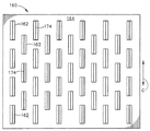
今や図面を参照すると、図1は、基部又は基材14の上に位置する複数の微細要素12を含有する参照番号10によって一般的に表記される微細構造の群列を図示する。図1において、微細要素10の各縦列は、次の隣接する縦列の類似の微細要素とは段違いである。しかしながら、所望であれば、縦列のそれぞれを互いに同一に作ることができ、段違いを外すことができる。あるいは、微細要素パターンが反復する前に種々の段違いを有する幾つかの縦列が存在してもよいし、又は反復パターンがないように段違いが実質的に無作為であってもよい。
【0054】
図2は、拡大図にて、四面ピラミッドの外観を有する微細要素12の1つを図示する。ピラミッドの各側壁は参照数字20で表記され、側面の間の継ぎ目又は「隅」は参照数字22に位置する。ピラミッドの頂点は24で図示され、各側面の底線は26に位置し、そこで基材14に接する。
【0055】
微細要素の配列10は、ヒトの手によって保持することができ、皮膚の特定の領域に置き、次いで前後にまっすぐ(又は、所望であれば円を描くように)動かすことができるパッチの中にそれを形成することによって皮膚の角質層を貫通するのに極めて有用である。パッチ又は配列10を皮膚に対して擦る場合、微細要素12は死んだ皮膚細胞を貫通しやすくし、押し付ける又は突き刺す動き(皮膚の表面に対して基本的に垂直である)の代わりに横に滑らす動き(皮膚表面に対して実質的に平行である)によって行う。
【0056】
配列又はパッチ10は、個々の微細要素12の配向に関してパッチ10の動きの方向に構わず、角質層を通って貫通するその機能を正確に実行する。言い換えれば、これらの微細要素12は操作において全方向性であり、全方向が好ましく、又は更に「予め設定される」。以下に記載される発明のその他の実施形態は全方向性ではなく、代わりに、個々の微細要素の配向性に関して事実上一方向性又は二方向性である。
【0057】
微細要素は、微細要素12の「突出長さ」によって制御される(及びおそらく実質的に同等である)予め定められた「貫通の深さ」に皮膚に切り込む。以下に記載される本発明のその他の実施形態は同様の方式で機能する。
【0058】
微細構造10のもう1つの特長は、コンディショナー、又は液体若しくはクリームの形態でのその他の種類の化合物を塗布する使用に対する性能である。微細構造のパッチ10が皮膚の領域に貫通した直後、角質層はその中に皮膚のバリア特性を十分に(少なくとも一時的に)低下させる多数の細隙又は切れ目を有する。ここで流体化合物を皮膚に適用することができ、それははるかに容易に表皮層に達する。所望であれば、流体化合物はある種の薬剤又は活性成分であることもできる。以下に記載されるその他の微細構造も皮膚の中に浸透する流体化合物のこの種の局所適用にうまく適合する。
【0059】
微細構造10のさらなる特長は、皮膚の領域に設置するのに先立って、基材14及び/又は微細要素12上に適用されるべき化合物に対する性能である。微細構造のパッチ10を皮膚に置く場合、それはこの化合物の一部を貫通されている皮膚の同一領域に付与する。このことは本質的には同時に行われる。以下に記載されるその他の微細構造も、この種の流体化合物を貫通されている皮膚の同一領域へ同時送達することにうまく適合する。当然、基材(例えば、図3及び4を参照)において貫通孔を含む以下に記載する実施形態は、この組成物送達の方法に対して第1選択であるというわけではないが、所望であればかかる装置はこの様式で確実に使用することができる。微細構造10の表面に事前に適用される化合物は、ユーザーが置いてもよいし、微細構造10の製造時に置かれてもよい。
【0060】
図3は、参照数字30により概ね表記され、貫通孔及び流路を追加している類似の微細要素群列を図示する。基部又は基材34は、個々のピラミッド形微細要素32の基部に近接して位置する複数の貫通孔36を含む。これらの貫通孔36は、基材34全体を貫通するか、又は基材を部分的に貫いて貫通孔に垂直方向に走ってもよい連絡路に接続することができ、多数の貫通孔の間に共通の接続を作る。
【0061】
図4では、さらなる詳細が見られ、ここでは、ピラミッド形微細要素32の側壁40は貫通孔36に接続する溝付き流路38を有するのが見られる。側壁40の縁部は参照数字42であり、ピラミッドの個々の底線は46であり、ピラミッドの頂点は44である。
【0062】
図3及び4では、32における複数のピラミッド構造の群列30はすべてピラミッドの各側面に隣接する貫通孔を有する。当然、所望であれば、ピラミッド形微細要素32当り更に少ない貫通孔が存在してもよい。あるいは、所望であれば、群列におけるピラミッド形微細要素32の一部は、隣接する貫通孔を有さなくてもよい。かかる微細要素(又は群列におけるその他)は、流路38に先んずることができる。
【0063】
図3及び4の構造は、貫通工程と薬剤送達工程を同時に実行するのに有用である。配列又は「パッチ」30が皮膚に沿って擦られている間、角質層の皮膚細胞は、個々のピラミッド形微細要素32によって切削され、切開され又は細隙が開けられ(又はさもなければ貫通され)、次いで皮膚表面のその領域を通って「注入される」いかなる種類の流体化合物に対しても皮膚を準備する。毛管力は、薬剤又はその他の活性成分を送達する利点に機能する。もちろん、例えば、機械的圧力又はイオン泳動を用いて送達を助けることができる。
【0064】
薬剤のような流体化合物を皮膚の中に送達する代わりに、例えば、間質液を試料採取するのに図3及び4で開示される微細構造を用いることができるのが理解される。その場合、例えば以下に記載されるように、流体の流れは、もちろん、貫通孔36を通る反対の方向であり、続いて回収容器又はチャンバーに向かう。
【0065】
パッチ10と同様に、配列又はパッチ30は、個々の微細要素32の配向に関してパッチ30の動きの方向には構わず、角質層の皮膚細胞を貫通するその機能を正確に実行する。言い換えれば、これらの微細要素32は操作において全方向性であり、全方向が好ましく、又は更に「予め設定される」。
【0066】
配列又はパッチ30のもう1つの可能性のある使用は、比較的長い時間間隔で微細構造のパッチ全体を皮膚に取り付け、それによって、前の擦る手順の間に形成された切れ目又は細隙を用いて流体化合物の表皮への長時間送達の能力を提供する。微細構造のパッチを皮膚に貼り付けることによって延長した時間間隔で生物学上流体の試料採取をすることも可能である。その上、特に、微細要素において1セットを超える孔が提供されれば(以下のその他のかかる構造を参照のこと)、又は少なくとも2群の微細要素が単一の基材上に提供されれば、この配置によって間質流体の試料採取と薬剤送達(例えば、インスリンの)を同時に行うことが可能である。第一の群(又は配列)が間質流体の試料採取を行い、一方で第二の群(又は配列)が薬剤を送達することができる。
【0067】
もう1つの微細要素の形状は図5で図示され、これは52で「立方長方形の」微細要素の群列50を具備する。これらの微細要素52は、立方体(箱形)の側壁を1つ取り除いた後の上部がない、中空の又は開いた立方体又は箱形のような構造の外観を有するカップ様形状を有する。図6の斜視図でこれを更に明瞭に見ることができる。(「立方体様構造」52は同一の長さ、幅、及び高さの外部寸法を有さないので、実際には幾何的立方体ではないことが理解されるであろう。この点に関して、用語「箱様」又は「箱形」がより記述的である。)
微細要素52の個々の縦列は、図5に見られるように、基材54において段違いである。代替的な構築では、所望であれば、これらの微細要素52の個々の縦列のそれぞれを同一にして、それによって段違いを除くことができる。さらなる代替として、微細要素パターンが反復する前に種々の段違いを有する幾つかの縦列が存在してもよいし、又は反復パターンがないように段違いが実質的に無作為であってもよい。
【0068】
図6は、個々の微細要素52のさらなる詳細を示し、それは「後壁」62、一対の「側壁」60、各側壁60の64における前縁部、及び側壁60の底に沿った底線66を有する。
【0069】
皮膚の角質層を貫通するために、微細構造又は「パッチ」50を文字「C」(好ましい、予め定められた方向)により表記された方向に沿って実質的に前後に擦る。この方式で、64における縁部は、皮膚細胞を通って、微細要素52の突出長さと実質的に同等である予め定められた貫通の深さに切削する、又は切開する。
【0070】
図7は、微細要素の類似の群列を図示し、参照数字70により表記される。それぞれの個々の微細要素72は、図5及び6における開いた箱様の微細要素52に類似する外観を有するが、微細要素72のカップ様領域には貫通孔76が追加されている。これらの孔は通常、基部又は基材74を完全に貫通するが、代わりに基材の中に部分的に延びてある種の内部流路に接続することができる。そのように、これらの孔はいかなる形状、直径又は長さの連絡路にもなり得る(又はそれに接続する)。
【0071】
微細構造の配列70は、皮膚に適用し、実質的に図7で示される「C」の方向において(好ましい、予め定められた方向)前後の方式にて擦る「パッチ」に成形することができる。図8はさらなる詳細を示し、そこには2つの側壁80、後壁82、2つの「前」縁部84、それぞれの側壁80に対する底線86、微細要素72の内部領域に近接する貫通孔76が存在する。前に記載された図3及び4の微細構造に類似の方式にて、図7及び8で開示された微細構造70を用いて、表皮の中にある種の活性成分を送達しながら、同時に皮膚表面を貫通することができる。かかるシステムにより、ユーザーは皮膚の外層の貫通及び表皮への送達の双方を単一操作で行うことができる。
【0072】
図9は、基部又は基材104の上に載せるくさび形微細要素102の群列100を図示する。前に記載した実施形態の幾つかにおけるように、微細要素102の各縦列は、図9に図示されるように、隣接する縦列と段違いであることができる。しかし、代わりに縦列は互いに同一に作られてもよく、その際、段違いは存在しない。さらなる代替として、微細要素パターンが反復する前に種々の段違いを有する幾つかの縦列を並べてもよいし、又は反復パターンがないように段違いが実質的に無作為であってもよい。
【0073】
図10の斜視図にて、くさび形微細要素102を更に詳細に図示する。構造の上面は114であり、2つの細長い側壁112、及び合流線で切削縁116を形成する一対の合流する側壁110が存在する。側壁110と基材104の間の接合部にて底線118も存在する。
【0074】
比較的鋭利な縁部116は、本特許文書に記載される方法において皮膚を切削する又は細隙を開ける(又は切開する)ために意図的に用いられる。くさび形微細要素102は全体として本明細書に記載されるその他の実施形態の一部よりも更に実質的な構造として提供される。それはおそらく図1〜8において、先に記載した微細要素よりも製造しやすい。図9における配列100の微細要素では、配列を「パッチ」として皮膚に適用し、次いで「C」の線に沿って(好ましい、予め定められた方向)実質的に前後の方式にて擦ることが好ましい。図9で見られるように、パッチ100をこの方式にて線「C」に沿って動かすときに、比較的鋭利な縁部116を用いて皮膚に切り込む。
【0075】
本質的に、縁部116は、角質層の死んだ細胞に対する微小な鋤として機能する傾向がある。鋤の作用の更に記述的な図が図27に提供されており、その図は皮膚に細隙又は切れ目を作る際の「まっすぐな」くさび形をした微細要素102の1つを図示している。皮膚は300にて表現され、表2つの合流する面110によりできた鋭利な縁部116が、先端部302で開始して、角質層の上部分を通って本質的に鋤で刻み、それによって306で線に沿って皮膚が引き離されるのが見られる。これは、皮膚の内部部分を一時的に304にさらしたままにする。
【0076】
図27では、微細要素102は実質的に矢印「C」の方向に動き、それによって皮膚がその方向で切削されていることを示している。もちろん、微細要素102が反対方向に動くとき、それは反対方向で皮膚を切削し、新しい細隙を形成し、又は既存の細隙を拡大する傾向がある。
【0077】
微細要素の種々の深さ及び微細要素の幅を構築して皮膚に作られる細隙の大きさ及び貫通の深さを増やしたり減らしたりすることができるのが理解され、かかる寸法の変更物は本発明者らにより想定されている。確かに、本発明の原理から逸脱することなく、正確な形状及び大きさを変化させることができる。
【0078】
図11は、120における類似のくさび形微細構造群列を示し、それは、126にて2つの別個の貫通孔を有する個々のくさび形微細要素122を有する。微細要素122はすべて基部又は基材124に取り付けられる。図11に見られるように、微細要素122の縦列は、それらが隣接する横列で互いに段違いであるという点で、互いに幾分異なっている。これは必須ではなく、代替的には、所望であれば、縦列を互いに同一にして段違いを除くことができる。再び、代替的には、微細要素パターンが反復する前に種々の段違いを有する幾つかの縦列が存在してもよいし、又は反復パターンがないように段違いが実質的に無作為であってもよい。
【0079】
図12は、個々の微細要素122を更に詳細に示し、そこでは、鋭利な縁部136に達する、合流する側壁130と共に、上表面134及び細長い側面132が示される。微細要素122と基材124との間の接合部として底線138も描かれる。孔126は、基部又は基材全体を貫通しないが、その代わり、所望であれば、ある種の垂直の流路又は連絡路に接続する連絡路になることができるが、貫通孔126は、微細要素122全体を貫通するように作られ、好ましくは基部124全体を貫通する。微細要素122当り2つの別個の孔126が存在するので、所望であれば、単一操作で2つの異なった活性成分(単一の微細要素における孔当り1つ)を同時に送達することが可能である。
【0080】
微細要素122は、単一の工程で皮膚の貫通機能と送達手順の両方を実行するように設計される。この特別の構造では、送達孔又は連絡路126の中で死んだ皮膚細胞及びその他の異物の蓄積が欠けることをほぼ保証することができる。これらの通路126で異物又は死んだ細胞の一部が蓄積したとしても、毛管作用の結果として、通路126を介して少なくとも1つの活性成分又は薬剤の皮膚の少なくとも表皮層への送達を達成する。
【0081】
図13は、基部又は基材144に取り付けられる多数の個々のくさび形微細要素142を含有する、参照数字140で表記される微細構造群列を図示する。これらのくさび形微細要素142は貫通長穴146を含有し、角質層が貫通された直後、それを介して少なくとも1つの活性成分又は薬剤を皮膚の外側表面を通って送達することができる。図11の構造に類似する方式にて、微細要素の配列又はパッチ140を好ましくは皮膚上に置き、「C」の方向に沿って(好ましい、予め定められた方向)前後の方式にて実質的に擦り、角質層の皮膚細胞を貫通する又は切削する。
【0082】
図14は、個々の微細要素142のさらなる詳細を示しており、上表面154、側壁152、比較的鋭利な縁部156に達する、合流する側壁150、及び微細要素142が基部又は基材144と接合する底線158を示す。
【0083】
貫通長穴146は、図12の微細要素122に比べて、少なくとも1つの活性成分又は薬剤を皮膚表面に送達するための更に大きな横断面領域を提供することができる。当然、微細要素142の実際の寸法は、図12で図示される類似の微細要素122よりも大きいか、又は小さいかのいずれかであることができる。貫通長穴146を持つものの方が複数のより小さな貫通孔126を構築するのに比べて構築するのが幾分容易ではあるが、微細要素122及び142のセットは双方共、比較的構築するのが簡単である。
【0084】
前の実施形態の一部で記載されたものに類似の方式にて、パッチ又は配列140を皮膚の貫通及び少なくとも1つの活性成分の送達の組み合わせ工程のために用いることができる。本発明の原理から逸脱することなく、その他の類似するくさび形構造を容易に構築することができる。
【0085】
図15は、基部又は基材164に取り付けられる、三角形をしたくさび形微細要素162の群列又はパッチ160を開示する。図16に見られるように、微細要素162はそれぞれ細長い三角形形状から成り、一対の三角形の側壁170、一対の傾斜を持った細長い側壁172、上縁部174、及び一対の底線178を有する。三角形の端部壁170と長方形だが傾斜のある側壁172との間の接合部は参照数字176で表記される。三角形の頂点は174で図示され、それは、微細要素162の上縁部174に沿った1点のみである。
【0086】
これらの三角形の形状をしたくさび形は、皮膚の貫通手順で有用であることができ、また好ましくはパッチの形態で皮膚の上に置かれ、次いで皮膚上で実質的に「C」の方向(好ましい、予め設定された方向)に前後に擦られる。微細要素の個々の縦列は、図15に見られるように、隣接する縦列において互いに段違いであることができる。あるいは、縦列はいかなる段違いもなく、互いに同一であることができる。もう1つの代替は、微細要素パターンが反復する前に種々に段違いを有する幾つかの縦列を並べてもよいし、又は反復パターンがないように段違いが実質的に無作為であってもよい。
【0087】
図17は類似の微細要素群列180を開示しており、それは基部又は基材184の上に置かれる又は形成される個々の微細要素182としての三角形をしたくさび形を有する。「パッチ」180において、少なくとも1つの活性成分を角質層を通して入れるための複数の貫通孔186及び流路188が存在する。
【0088】
図18は拡大図にて流路188及び孔186を示し、その際、孔186は通常基材184全体を貫通するように設計される。しかしながら、かかる孔186は、基部構造自体の中で別の型の連絡路に接続するのであれば、部分的にのみ貫くことができる。
【0089】
三角形をした微細要素182は、縁部196に沿った傾斜のある長方形の側壁192と接続する側壁190に沿って図18に見られる。上縁部194は2つの三角形の側壁190の間に存在し、底線198は、微細要素182と基材184の間に線を引く。
【0090】
図18では、細長い側壁192の表面に三つの別々の流路188が存在する。当然、所望であれば、更に少ない流路を利用することができ、又は更に一層多くの流路を使用することができる。微細要素182の間の領域が死んだ皮膚細胞及びその他の異物で実質的に満杯になったとしても、これらの流路188は、毛管作用によって、孔186を介し、流路188に沿って、少なくとも1つの活性成分が角質層の中に流れることに役立つ。
【0091】
図16及び18双方の三角形のくさび形構造は、基本的に皮膚の角質層を貫通するように設計される。これは、図15及び17に示すように実質的に「C」の方向にて前後の方式で微細要素パッチ160又は180を動かすことによって達成される。もちろん、微細要素パッチが異なる方向、特に線「C」(好ましい、予め設定された方向)に垂直の方向に動くならば、皮膚が切削されず、貫通されないことは大いにあり得る(パッチが意図する「C」方向で用いられる場合と比べた場合、少なくともその程度までは切削されず、貫通されない)。これは大きな有用性を有するが、この概念は本発明の一部ではない。代わりに、その種類の方法は、2001年9月14日に出願された出願番号第09/952,403号(これもまた、プロクター&ギャンブル社に譲渡されている)の「皮膚の治療及び調子を整えるための微細構造(Microstructures for Treating and Conditioning Skin)」という名称の関連特許出願に開示されている。
【0092】
三角形をしたくさび形のもう1つの改良が、図19及び20で図示されている。図19では、微細構造の群列又はパッチ200は、基部又は基材204に置かれる又はその上で形成される複数のくさび形微細要素202を含有するとして図示されている。図20に見られるように、それぞれの微細要素202は、三つの別々の三角形をしたくさび形から構成され、それぞれは206にてその間の空間を有する。
【0093】
図20では、三角形をしたくさび形202の三つの区分が三角形をした側壁210、一対の長方形の傾斜のある側壁212、上縁部214、及び微細要素202が基材204と接合する底線216を含むのを見ることができる。それぞれ三つのくさび形形状は空間206によって分離され、その際、中央の三角形のくさび形形状は、両側を第二の外側の類似のくさび形形状で囲まれ、空間領域206によってこれらの外側のくさび形形状のそれぞれから離れて空間を空ける。
【0094】
三つの別個のくさび形の微細要素202(間隔206によって分離されている)は更に個別の切削縁214を提供する。パッチ200が線「C」に実質的に沿って動く場合、三角形の端部壁210の各頂点は新しい切削又は「刻み」点を表す。
【0095】
配列又はパッチ200の好ましい使用は、パッチを直接皮膚に適用し、次いで、図19に見られるように実質的に「C」の方向(好ましい、予め定められた方向)にて前後の方式にて皮膚に沿ってパッチを擦ることである。この特定の設計は皮膚の外層をかなりうまく貫通するが、同時に活性成分を適用するようには設計されていない。微細要素182に関して図18で開示した形状を用いる場合、そのタイプの構造はおそらく構築しやすいが、所望であれば、当然、貫通孔及び流路をこの構造に加えることができる。
【0096】
微細要素パッチは、本発明の理念から逸脱することなく、いかなる1つの形状の微細要素でも構成することができ、又は単一の基材又はパッチの構造上で幾つかの異なった形状から構成されることができることが理解されるであろう。更に、本発明の原理から逸脱することなく、本明細書で開示される微細要素は、同一の基材又はパッチの上ですべて同一の高さであることができ、又は異なった高さであることができることが理解されるであろう。最後に、図面において開示された形状への些細な改変が発明者によって熟考され、それは、本発明の原理の中にやはり当てはまることが理解されるであろう。
【0097】
貫通孔又は貫通長穴を含有する微細要素群列又はパッチは、群列を組成する個々の微細要素1つ1つに、かかる貫通孔又は貫通長穴を有する必要はないことが理解されるであろう。言い換えれば、微細要素を通って(又はそれに隣接して)流れる連絡路は、所望であれば微細要素の半分だけに構築することができるが、かかる貫通孔又は貫通長穴が微細要素のそれぞれで見い出されるときに達成される成果のほとんどを依然として達成する。確かに、孔又は長穴は大きさ又は直径を変更して、それを流れる流体物質の量を減らす、又は増やすことができる。これらの変化のすべては発明者らによって熟考され、本発明の原理の範囲内に入る。
【0098】
一般に、上で記載された本発明の微細要素は、剥脱にのみ用いられるものよりも長く、微細要素の長さは通常、50〜1000ミクロンの範囲である。これによって微細要素が角質層を貫通することができる。上記のように、図1、3、及び21ではパッチを滑らす方向は重要ではないが、図5、7、9、11、13、15、17及び19では、滑らす方向はより重要であり、またほぼ矢印「C」で表わされる方向であるべきである。これにより微細要素は皮膚を切削し、角質層をある程度まで貫くであろう深さまで皮膚を貫通することが可能になる。これによって活性成分又はその他の種類の流体物質又は流体化合物(例えば、液体又はクリーム)がはるかに容易に角質層を通って浸透することができる。
【0099】
図21は、ある種の「コイル状の付属体」を図示しており、222において複数の湾曲したくさび形をした微細要素が基材224の上に置かれ、一般に参照数字220で表記される配列又はパッチを形成する。図22は、これらの弓状の微細要素222の1つを更に詳細に図示する。微細要素222は、縁部236で合流する比較的平坦な表面230からできた2つのくさび形をした先端部を含む。縁部236にて2つのくさび形をした「切断面」は、側壁232、上面234、238にて底「線」を有し、湾曲した又は弓状の形状である湾曲した本体に接合する。
【0100】
配列又はパッチ220は、パッチを皮膚表面に置き、次いで、文字「C」で表記される弧にほぼ沿ってパッチを回転することによって用いられる。これは、比較的鋭利な縁部236に沿って湾曲した微細要素222のどちらの方向においても皮膚に細隙を開けやすく又はさもなければ切削しやすくする。
【0101】
配列/パッチ220上の湾曲した微細要素222は次の2つの方法に用いることができる:(1)皮膚を最初に切削し、パッチ220を取り除き、次いで流体化合物(例えば液体物質又はクリーム)を皮膚に適用する;(2)流体化合物を最初に皮膚に適用し、次に配列/パッチ220を皮膚の同じ領域上に押し付け、及び開口部を作るために回転し、それにより流体化合物を角質層を通ってより容易に浸透させる。
【0102】
類似する弓状の又は湾曲したくさび形構造は図23に図示され、242における個々の微細要素は基材244の上に置かれて配列又はパッチ240を構成する。これらの湾曲したくさび形はまた「コイル状」構造と呼ばれてもよい。微細要素242の1つが図24に更に詳細に図示され、貫通孔246が微細要素242の上面254を通って置かれているのが見られる。弓状の微細要素242により角質層に細隙が開けられた、又はさもなければ貫かれた後、これによって流体化合物が孔246を通って皮膚の中に入ることができる。湾曲した各微細要素242は、256にて、線256に沿って合流する比較的平坦な側面250によってできた一対の鋭利な縁部を示す。湾曲した構造は側壁252、上面254、微細要素242が基材244に接合する258にて底「線」又は弧を有する。
【0103】
図23、及び24の構造では、パッチ240は通常皮膚表面上に置かれ、次いでほぼ曲線「C」により表記される方向に回転する。角質層全体を浸透すべき流体化合物は、ある種類の容器又はチャンバー(又はおそらくは不織布含浸材料)内に既に含有されており、それは次には毛管作用によることを含んで、孔246を通って滲出する。
【0104】
別の構造が図25に図示されており、湾曲した微細要素262は、266にて、やはり弓状形状である貫通長穴を示す。湾曲した微細要素262は基材264の上に置かれ、全体としての構造が配列又はパッチ260を構成する。図26は、個別の微細要素262を更に詳細に示し、湾曲した微細要素の2つの末端276での鋭利な縁部を図示しており、これは合流する側壁270からできる。湾曲した側壁272は、上面274及び微細要素262が基材264と接合する278での底「線」又は弧と共に図示される。貫通長穴266は図26で容易に見られる。
【0105】
弓状の微細要素262は、図24で図示されたものと同様の方式で用いられ、配列/パッチ260は皮膚の上に置かれ、弧「C」に沿って実質的に回転され、次いで流体化合物が、所望のように長穴266を介して角質層を抜けて通ることができる。
【0106】
図28は、くさび形をした微細要素102を立面図においてその「鋭利な」末端から図示している。2つの合流する側面110は、基材/基部104の上部から微細要素102の上表面114に垂直に走る116にて比較的鋭利な縁部を形成するように見える。104における基材上表面と側壁112との間の角度「A」が明瞭に見える。図28では、この角度「A」はおよそ90°であり、従って垂直の角度を形成する。
【0107】
図29は、参照数字402により表記されるくさび形をした微細要素の別の形状を示す。このくさび形微細要素は、その細長い側壁が基材に対して垂直に形成されないことを除いて、上から見てくさび形微細要素102に類似する外観を有する。
【0108】
図29では、基材404は、90°より大きい角度「A」で微細要素の側面(即ち、壁412)に沿って伸びる外壁に接合する。その相補的な角度は「B」に図示される。角度Bは、図29では45°〜60°の間であるが、もちろん、皮膚の貫通をうまく操作するいかなる角度であることもできる。
【0109】
合流する前壁は410で図示され、416にて比較的鋭利な縁部に沿って合流する。微細要素402のこの垂直ではない壁形状は、製造に関して及び構造の全体的強度に関して幾つかの利点を有し得る。
【0110】
図30は、異なった形状の微細要素の配列を含有する微細構造及び参照数字460で表記される対応する基材、並びに参照数字470で表記される下にある容器構造の部分的横断面における側面正面図である。図30では、微細要素の配列460は、ピラミッド形の側面に沿った溝又は流路38を有するピラミッド形微細要素32のセット、及び貫通孔126を有するくさび形をした微細要素122のセットを有するとして図示される。基部又は基材は参照数字462で表記される。
【0111】
図30では、貫通孔は実際、微細要素及び基材462の双方を通るあらゆる道を走り、通路を形成し、これらの通路が2つの群で表わされる。第一の群は、ピラミッド形微細要素32における溝又は流路38の組み合わせであり、それは貫通孔464に接続され、基部又は基材462の底面表面から基材462の上面を通って延びる通路の共通のセットを形成し、流路又は溝38と接続する。通路の第二のセットは、貫通孔466のセットを具備し、くさび形をした微細要素122の微細要素貫通孔126と接続する。これらの貫通孔126及び466は互いに位置が合い、微細要素122の上部から462の基材の底面まで完全な通路を形成しなければならない。当然、所望であれば、類似の連絡路に接続する何らかの水平な流れが存在してもよい。
【0112】
図30で表現される底部分470は、472における底壁及び474で容器の側壁によって境界が示される476における容器領域又は容器容積を有する容器構造を含む。複数の活性成分を格納するために、複数のかかる区画又はチャンバーを構築することができる。この容器構造470の上部部分は参照数字478にて表現されるように、通常、平面であり、460での微細構造/基材装置の468における底面表面と接触する。容器476は通路464及び466と水圧で又は空気圧で接続し、それによって、使用するまで476にて容器の中に流体の薬剤又はその他の活性成分を閉じ込め、次いで流体の薬剤又は活性成分が通路464及び466を介して微細要素32及び122の上部表面を指向できるようにすることが重要である。
【0113】
図31は、参照数字100で表記される微細構造装置を構成する、基材104上のくさび形をした微細要素102の配列を図示する。微細構造装置100は、不織布の裏打ち502に積層する上層を具備し、それは好ましくは実質的に柔軟であるように十分薄い。この全体的な構造は一般に図31における参照数字500によって表記される。
【0114】
複数の微細要素102を含有する上層100は、基材及び微細要素の材料として、例えば、ナイロン、又はポリカーバイド物質、又はPMMAのようなある種の成形可能なプラスチックを有することができる(及びこれらの物質はいかなる微細要素の形状と用いてもよい)。底面又は裏打ち材502は、好ましくは、柔らかい質感を示す実質的に柔軟な材料である。通常、不織布材は、布の印象を与えるので、所望の柔らかい質感を提供することができる。
【0115】
不織布の裏打ち材502は、例えば化学糊又は加熱活性化接着剤の使用によって、微細要素の層100に積層することができる。図31では、不織布の裏打ちが長さと幅において微細要素層100よりも幾分大きいため、縁部に沿ってそれを見ることができる。
【0116】
図32は、類似の積層した構造を図示するが、微細要素102は細片512として形成され、その際、微細要素の列を含有するかかる細片が幾つか存在する。図32では、不織布の裏打ち材は、上部及び底面の縁部に沿って、及び514にて細片の間で見ることができる。全体的な構造は参照数字510によって概ね表記される。
【0117】
図33では、微細要素102は、基材104の上に存在するものとして上部で見られる。基材の底部分は、不織布の裏打ち材502に永続的に貼り付けられており、従って500にて総括的構造となる。
【0118】
上で議論したように、基材104への不織布の裏打ち材502の固定は、積層で用いられたある種の接着剤によって、又はおそらく音波接着法の使用によることができる。あるいは、一緒に押し出した材料を用いることができる。
【0119】
図31〜33で表わされるような不織布の裏打ち材を用いることの1つの主な利点は、この不織布材502(又は図32の514)が少なくとも1つの活性成分を含浸させることができ、それによって開いた容積空間を有する実際のチャンバーを作ることなく、効果的に「容器」となることである。これによって、実際の開放チャンバーが構築される必要がないことにより製造手順の工程が省かれるだけでなく、破損問題を呈する可能性がはるかに少ない実質的に柔軟な材料で先の図に見られる「パッチ」の全体的な構造を構成することもできる。
【0120】
種々の形状の微細要素を不織布の裏打ち材と共に用いることができ、また種々の形状の基材を不織布の裏打ち材に積層することができ、さもなければ貼り付けることができることが理解されるであろう。裏打ち材は含浸されてもされなくてもよいが、すべて本発明の原理から逸脱しないということも理解されるであろう。最後に、不織布材の他にその他の好適な材料を、図31及び32の502及び514での裏打ちにて用いることができ、すべて本発明の原理から逸脱しないことも理解されるであろう。
【0121】
図34は、皮膚を貫通するための微細構造について、上記の微細構造と比べて完全に異なる手法を図示している。概ね参照数字600により表記される回転可能構造は、円筒形基材604から突き出る又は延びる(即ち、曲線状の基材に貼り付けられている)複数の微細要素602により覆われている。図35に図示されるように、微細要素602の各々は1対のくさび形の縁部を616に有し、これは縁部616で接する側壁610により形成されている。側壁610は、2つの長手方向遠位末端又は縁部(616)から、微細要素602の両側に現れるもう1つの側壁612により分離されている。側壁612及び端部壁610は、上面614により境界が示されており、これは参照数字606によりほぼ表記される貫通長穴を含む。円筒形の回転可能構造600内に貯蔵された流動物質は、長穴606を通って流れ出すことができ、それにより皮膚の中に分配される能力を有する。
【0122】
微細要素602は、上の図13及び14の参照数字142で記載されたものと形状が非常によく似ている。微細要素602は、皮膚及び角質層全体を貫通するように設計されており、それにより流体物質が長穴606を通って分配され皮膚の中に浸透することが可能になる。
【0123】
かなり独特の構造がそれにより開示され、ここでは、回転可能構造600は軸部材を608に有し、これはある種類のローラー構造に取り付けられることができ、それにより回転可能構造600の円筒形の形状は矢印「C」により示される両方向に回転することが可能になる。理想的には、円筒形構造600は皮膚上に置かれ、次いで皮膚の表面に沿って動く間に円筒が回転するように並進運動で動かされ、それにより構造600が回転する間に、個々の微細要素602が皮膚に切り込み、角質層を貫通することが可能になる。
【0124】
回転可能構造600の変形が図36に図示され、ここでは、参照数字622により概ね表記される微細要素は、図34及び35に見出されるそれらの微細要素602とは異なる形状を有する。全体的な回転可能構造は、図36の参照数字620により概ね表記され、そこから突き出る又は延びる複数の個々の微細要素622を有する基材624から構成される円筒形の形状を示す。回転可能構造620が皮膚に対して回転し押し付けられると、円筒形構造620が矢印「C」により示されるいずれかの方向に回転するときに、微細要素622の鋭利な縁部は、好ましくは皮膚の角質層全体を貫通する。
【0125】
微細要素622の単一のものの拡大図が図37に提供され、ここでは、側壁630は実質的に鋭利な縁部636で接する。これらの鋭利な縁部は、円筒形構造620が回転する間に皮膚に対して押し付けられたときに皮膚の角質層を貫通することができるようになっている。側壁630の上縁部は上面634により境界が示されている。
【0126】
図36及び37は複数の開口部又は貫通孔626を図示し、これらは微細要素622の周りに設置されている。流体物質(例えば薬剤)が円筒形構造620内に配置される場合は、そのときは構造620がCの方向に回転するにつれてその流体物質は開口部626を通って皮膚上まで通過することができる。
【0127】
回転可能構造600又は回転可能構造620が素早く回転する場合、そのときは遠心力により、流体物質は開口部(貫通長穴606又は貫通孔626のいずれか)を強制的に通過させられる。しかしながら、他の構造により更に正圧を生成することができ、これは以下に記述する。これらの代わりの圧力源も転がる動きにより作動させることができる。
【0128】
微細要素と基材との組み合わせは、円筒の形状に巻き付けるのに十分可撓性であるシートとして形成することができることが、理解されるであろう。かかる状況では、シート構造はエンボス加工手順又はおそらくは成形手順により形成することができる。製作方法としてエンボス加工手順が使用される場合は、そのときはおそらく製造業者により連続的エンボス加工操作が選択されるであろう。別の方法として、円筒形の形状は、成形処理により直接形成され得る。
【0129】
円筒の外面上での微細要素の実際の配置は本質的には設計者により選択されるいかなるパターンであることもでき、その際微細要素は直線、又はねじれ形の配置、又はおそらく、より無作為の様なパターンで形成され得ることもまた理解されるであろう。円筒形表面上のそれらの配置における微細要素とパターンとの間の距離の本質的にいかなるセットも本発明者により考察されるが、本発明の原理からけっして逸脱していない。
【0130】
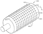
図38は、上に複数の微細要素を含有する円筒形の形状の回転可能構造のもう1つの別の実施形態を図示する。全体的な円筒形構造は参照数字640により概ね表記されるが、これは基材644の上に置かれるか又は基材644から突き出る複数の微細要素642を含有する。複数の開口部又は貫通孔は646に示されるが、これらは回転可能構造640内に貯蔵された流体物質をこれらを通って皮膚表面上まで通過させることを可能にする。微細要素642は少なくとも皮膚の角質層全体を貫通するように成形され、それにより円筒形構造640が皮膚表面上を転がるときに、流体物質が皮膚の中に浸透することを可能にする。
【0131】
図34〜37に開示されたそれらの微細要素602及び622に反して、図38では、個々の微細要素は対称形の形状ではない。図39で見られるように、微細要素642はこの側面図では直角三角形のような形状をしており、この側面図は遠位末端656で先がとがる側壁650を示している。円筒形構造640が矢印「C」の方向に回転するとき、遠位末端を656に有する三角形の側面は、参照数字658で表記される皮膚の中にはるかにずっと容易に貫通するであろうことが図39において見ることができる。もちろん、三角形の微細要素642の斜辺652(図40参照)が側壁650の間で十分に鋭かった場合には、そのときはこれらの微細要素は矢印Cの反対方向に転がされる間にまた皮膚を貫通する可能性があるが、これはこの実施形態の主な目的ではない。
【0132】
別の微細要素の形状は図40〜42に開示されており、円筒形構造640と共に用いることができる。図40では、微細要素642が2つの側壁650を示すものとして図示され、2つの側壁650はそれらの間の652に共通の縁部を有する。三角形の端部壁は654に形成され、これは図38にも見られる。この三角形の端部壁654の頂点は、上述の参照数字656の遠位末端又は遠位点である。皮膚の中への主な貫通をするのはこの点である。
【0133】
図40では、微細要素642の側面図D−Dが、この図形の水平線及び参照数字654で表記される垂線により境界が示されている直角を有するとして表わされている。参照数字654は実際には上述された三角形の端部壁である。側壁650は、656に頂点を有するとして図示され、これは斜辺652を下って延びている。水平線と垂直な端部壁654との間の直角は、図40で「Z」として参照される角を形成する。
【0134】
図40には2つの立面図があり;第一の図はA−Aと表記され、これは端部壁654を、三角形の形状であり、656の遠位末端又は頂点で先がとがる2つの側壁650を有するとして図示している。図A−Aの三角形の形状は正三角形であることもできるし、又は図A−Aの線部分650により構成される2つの等しい辺を有する二等辺三角形でもあり得ることが理解されるであろう。もちろん所望であれば、二等辺でないものも提供され得る。もう1つの立面図はB−Bであり、これは微細要素642の反対側の端部からのものである。図B−Bは比較的鋭利な縁部652で接合する側壁650を示し、これはすべて頂点又は上部点656で交わる。
【0135】
図41は、図38〜40に見られる微細要素642を置き換える、又は微細要素642と共に用いるための微細要素の別の実施形態を図示している。図41の別の微細要素は、参照数字668により概ね表記される。図41に見られるように、微細要素668は、側面図E−Eから見ることができる異なる角Zを有しており、側面図E−Eは、角Zが直角ではなく鈍角ではあるが、側壁660が三角形の形状を有することを示している。微細要素668の端部壁は参照数字664で表記されるが、これもまた三角形の形状を有し、遠位末端又は遠位点666で上部点又は頂点に達する。側面図E−Eから見られる三角形の斜辺は、参照数字662で表記される。図41のもう1つの図では、両方の側壁660が、縁部662で接するとして見られる(これはもう1つの図で見られる三角形の斜辺である)。上部点又は遠位点666は、図38に見られるものと類似した円筒形構造の回転により、微細要素668がCの方向に動かされるときに、主要な切断面を形成するであろうことがわかる。
【0136】
図42は、微細要素642のもう1つの別の実施形態であり、ここでは、この別の微細要素が参照数字678により概ね表記され、側壁670を示す側面図G−Gに見られるように、Zに鋭角を示している。この図G−Gにおいて、鋭角Zは水平線及び端部壁674により境界が示され、これは遠位末端又は遠位点676で上部点又は頂点に達する。この三角形の形状の斜辺は、参照数字672のところである。
【0137】
端面図F−Fがまた図42に提供されており、ここでは、端部壁674が三角形の形状を有するものとして図示され、側壁670により構築され、これらは頂点又は上部点676で接する。端部壁674の三角形の形状は、微細構造の設計者が所望するのに応じて、正三角形、二等辺三角形、又は全体的に非対称であり得ることが理解されるであろう。
【0138】
図42の平面図は、微細要素678を、2つの側壁670、端部壁674を有するものとして図示しており、それらのすべてが上部点又は頂点676で接する。2つの側壁670は、672の縁線に沿って接し、これが図G−Gの斜辺を形成する。図42に見られるように、微細要素678の形状は、通常は、図38の640の円筒形構造に類似した円筒形構造の回転により微細要素678がCの方向に動かされるときに、頂点又は上部点676と共にその端部壁表面674が容易に皮膚に貫通することを可能にする。
【0139】
図43から始まる次の数個の図は、多数の微細要素602を含有する回転可能構造600と共に用いる種々の別の実施形態を図示している。いかなる適切に成形された微細要素も、本発明の原理から逸脱することなく、これらの別の実施形態の実質上どれにも用いることができることが理解されるであろう。主な目的が皮膚を貫通することであることに留意すると、次の数個の図に開示される微細要素のすべては角質層を貫通することができ、薬剤又はその他の流体化合物を角質層を通して皮膚の中に送達することができる。
【0140】
ここで図43を参照すると、参照数字700により概ね表記される手持ち式ローラー構造が表わされており、これはシャーシ又は本体702、三つの軸608、及び微細要素を含有する三つの円筒形構造600を有する。このローラー構造700が皮膚704に対して押し付けられ、矢印「C」のいずれかの方向に動かされるとき、微細要素は皮膚の上層全体(即ち、少なくとも角質層全体)を貫通し、それにより薬剤又はその他の流体化合物を皮膚の中へ送達させる。この実施形態700は、代替案として微細構造システムの設計者が所望するのに応じて、単一の円筒形ローラー600、又はかなり多数のかかるローラーを具備することができることが理解されるであろう。その上、複数の円筒形構造が全体的な装置700に用いられる場合には、そのときは異なるローラーの微細要素のパターンは同じであることもできるし、又は所望であれば異なることもできる。「パターン」という語の使用は、円筒形ローラーの内の1つの基材上の微細要素の位置について異なる配置での同じ形状の微細要素か、又は異なるローラー上の異なる形状の微細要素かのいずれかを示唆し、その際第一の微細要素の形状は第一のローラー600上に見出され、第二の微細要素の形状は第二のローラー上に見出されるか、又は単一ローラー上に形状の何らかの組み合わせが見出される。
【0141】
ここで図44を参照すると、単一ローラー600が図示されており、ここでは、この単一ローラーは、多数の微細要素を含有する回転可能構造である。ローラー600は、アーム714に取り付けられ、これは人の手により保持され得る延びる部材712に更に取り付けられる。全体的な構造は参照数字710により概ね表記されるが、これは部材712、アーム714、及び円筒形の回転可能なローラー構造600を含有する。円筒形の回転可能なローラー構造600が皮膚718上に置かれ、次いで矢印「C」により表記されるいずれかの方向に動かされるように、この構造710が保持されるとき、薬剤又はその他の流体化合物を皮膚の中へ送達させるために、個々の微細要素は皮膚(好ましくは角質層全体)を貫通する。図43の参照において上に記載したように、ローラー600上の微細要素は、同じ種類(即ち、大きさ及び形状)であることができ、また直線のような対称パターンに配置されることができ、あるいはねじれ形の配置を有することもでき、又はもう1つの別のものを考慮すると、微細構造の設計者が所望する場合には、微細要素は異なる大きさ及び形状であることができる。もう1つの別の実施形態は図45に図示され、ここでは、参照数字720により概ね表記される全体的な手持ち式ローラー構造が円筒形ローラーを提供し、これは参照数字601により表記される。本体又はシャーシ722は人の手が接触し、またこの本体722は、流体化合物726を含有する容器を724に含有する。流体化合物726は、人が上部ボタン728を下に押すことにより分配されるが、このボタンを押すことは容器(又はチャンバー)内部に圧力を生成する。これが生じると、流体726は通路を通って、730の皮膚の表面に近接する出口728に分配される。
【0142】
ローラー600の円筒形表面は、一回使用の用途のために使い捨てに製造することができる。微細構造の円筒形表面は、図43に図示されるような「シャーシ」の実施形態を含む、本特許文書に開示されるすべての実施形態用に使い捨てに製造することができることが理解されるであろう。
【0143】
微細要素が使用された後に微細要素の機能性を破壊すること、特に一回使用の用途(即ち、使い捨てローラー又は使い捨て滑り部材など)について幾つかの利点があることも理解されるであろう。廃棄処理は、所望であれば内蔵式装置を用いて達成することもできるし、又は例えば鋭利な縁部を押しつぶす又は融解する、独立した別個の微細要素破壊装置を用いて達成することもできる。
【0144】
本体又はシャーシ722はまた、ローラー601を所定の位置に保持する軸608を含有する。全体的なローラー構造720が矢印「C」の方向に動くとき、出口728を通って分配される流体は、図45の732に見られるように、皮膚表面の上部に薄層を形成する。回転可能なローラー601はこの流体層732の上を通り、微細要素が角質層を通って皮膚の中に切り込むときに、この流体層732は皮膚のこれらの開口部を通って下にいくことを強制され、図45の734の、皮膚の上層の下の流体の「層」となる。本特許文書に開示される他の実施形態にあるように、回転可能なローラー601上の微細要素の正確な大きさ及び形状は、角質層全体を切削し流体が角質層を通って皮膚の中に運ばれる目的を果たす一方で、すべてが本発明の原理から逸脱することなく多くの異なる大きさ及び形状であることができる。
【0145】
このローラー構造の実施形態720では、ローラー601の円筒形表面上に形成される微細要素は通常は開口部を有さず、突起のみを形成する微細要素を具備する。出口728での圧力は、開口の大きさ及び/又は流体の通路の形状により制御することができ、それにより流体の分配速度が制御されることが理解されるであろう。
【0146】
本発明のもう1つの別の実施形態が図46に図示され、ここでは、全体的ローラー構造740は本体又はシャーシ742を具備し、これはその内部に異なる種類の流体チャンバーを含有し、またもう1つの微細要素の円筒形ローラーを具備する。人の手に本体742が保持されるとき、ローラー構造740全体は矢印「C」の方向に押されることができ、これは円筒形の回転可能なローラー601を軸608の周りに回転させる。この回転は、ウォームギア760と円筒形ローラー601との間の回転の比率を制御するために用い得るギアボックス603を通して、ウォームギア760を回転させる。
【0147】
ウォームギア760は、主ネジ762と相互作用するが、これは容器又はチャンバー744内に位置する移動ナット764と相互作用する。ウォームギア760及び主ネジ762が正しい方向に回転するとき、図46に見られるように、移動ナット764は右の方に動き、それにより流体物質746を容器から外へ、出口流体通路を通って出口748まで押し出すが、この出口748は皮膚750の上面に近接している。
【0148】
ローラー構造740が、矢印Cにより示されるのと反対方向に動く場合に、移動ナット764がその並進運動の軸に沿って動くことを回避するために、小さい一方向のクラッチがギアボックス603内に含まれ得ることが理解されるであろう。これは1つの選択肢であり、経費検討が最も重要である場合には絶対に必要なわけではない。
【0149】
流体が出口748を通って分配されるとき、それは皮膚表面750上の752に薄層を形成する。円筒形ローラー601が近づき、皮膚及びこの流体層752に対して押し付けられるとき、それは角質層全体を切削し、且つ層752の流体物質を新しく形成された角質層の開口部を通して押し出し、それにより流体を皮膚の下に置き、図46の754に見られるように「層」を形成する。
【0150】
円筒形ローラー601の表面上に形成される微細要素は、円筒形ローラー601の内部機能から流体を分配する必要がないために、通常は貫通孔又は他の種類の開口部を有さず、その代わりに突起のみを具備することが理解されるであろう。その上、ローラー601の円筒形表面上に形成される微細要素は、設計者が所望するのに応じて具体的な用途に適合するために、本発明の原理から逸脱することなく、実質上いかなる大きさ及び/又は形状又はパターンであることもできる。
【0151】
もう1つの別の実施形態が図47に図示され、ここでは、流体のチャンバー又は容器は移動ナット764により分離されるとして表わされており、その際移動ナット764の右側(この図では)の流体物質は容積746の中に位置し、チャンバーの残りの部分は移動ナットの左側の容積744の中に位置する。移動ナット764は主ネジ762の回転により動かすことができ、これは矢印「R」により表わされる方向に回転するとき、移動ナットを右側に動かし、チャンバー746内のいかなる流体も出口を通り、更には749の複数の開口部を通って流体を提供する別の容積又は空間の中に分配される。この構造は図46に図示される移動可能な装置に使用されることができ、複数の出口749は、比較的広い区域の流体化合物が皮膚表面上に分配されることを可能にする。これに留意すると、角質層全体を切削するための微細要素を含有する円筒形ローラー構造は、ローラー構造の長手方向軸が主ネジ762の長手方向軸に平行であるように配置されると思われる。
【0152】
次の三つの図、図48〜50はなお更に別の実施形態を図示しており、ここでは、円筒形且つ回転可能な装置は、複数の微細構造内の複数の開口部を通って流体化合物を分配するために使用されている。ここで図48を参照すると、円筒形の回転可能な装置770が図示されており、これは最初に図34に図示された構造600に類似した、軸608、円筒形基材604、及び複数の微細要素602を含む。全体的な装置770はまた、円筒形構造600が矢印「C」の方向に回転するときに、軸608の長手方向軸の周りを回転する投与パドル774を含む。固定パドル772は、移動パドル774の開始止め及び終了止めとして用いられる。構造770がCの方向に回転するときのみ投与パドル774が動き、構造770が反対方向に回転するときには動かないように、ラチェット776及びポー(paw)778が用いられる。
【0153】
投与パドル774が角を成す方式で動くとき、それは全体的な円筒形ローラー600内の流体物質を押し出し、圧力を生成し、それにより流体物質を微細要素602内の開口部606を通して外に押し出す傾向がある。微細構造システムの設計者が所望するのに応じて、実質上いかなる大きさ又は形状の微細要素もこの種類の実施形態に有用であり得ることが理解されるであろう。
【0154】
所望であれば、投与を延長するために、ギアシステムを全体的構造770に加えることができる。ギアシステムがあってもなくても、全体的構造770は、矢印Cの方向への構造の回転に際し、投与パドル774がその開始止めからその終了止めの位置までの完全な回転をかなり迅速に行うように製造されることができる。
【0155】
図49及び50では、参照数字780により概ね表記される分配構造についてのもう1つの別の実施形態が図示される。組立品780は、外部ドラム781、内部ドラム782、ワイパー又は回転可能なパドル783、遊星板(planetary plate)784、遊星ギア785、及び少なくとも1つの支持体786を具備する。支持体786(又は1対の支持体)は、これらの図には図示されていないハンドルと連携する。
【0156】
外部ドラム782は、分配開口部又は貫通孔788を含有する複数の微細要素787を組み込んでいる。中央シャフト789は、外部ドラム781の端部に軸受支えを提供し、シャフト789は代わりに支持体786(又は1対の支持体)により支持される。外部ドラム781の軸受開口761は、ボス763を通って内部に延び、ボス763もまたギアの歯765をその外径の周りに組み込む。
【0157】
中央シャフト789はまたこの内部ドラム782の軸受支えも提供する。内部ドラム782は、ギアの歯765と同じ大きさ及びピッチを有するギアの歯769を備える内径表面を有する内部ドラムフランジ767を含む。シャフト789は、ボス763と外部ドラム781との間の遊星板(planetary plate)784のための軸受支え、内部ドラム782の閉鎖端を提供する。
【0158】
遊星ギア785は、遊星板(planetary plate)784内の長穴753内に回転可能に、及びスライド可能に設置されるスピンドル751を組み込む。長穴753は、1つの端部が、もう1つの端部よりも遊星板(planetary plate)784の外径から遠いように構築されている。遊星ギア785が長穴753を上に動かされると、それはギアの歯765及び769との動作連携に置かれる。組立品780が反対方向に回転する場合、遊星ギア785は長穴753を下に動かされ、ギアの歯769との機械的連携から外される。この構造の結果は、遊星ギア785がオーバーランニング・クラッチとして機能し、内部ドラム782に一方向の回転を提供するというものである。
【0159】
内部ドラム782は、非回転シャフト789にしっかりと貼り付けられたワイパー783からゆっくりと遠ざかる内部ダム755を含む。内部ドラム782は、それを通って突き出る長穴又は孔757も備え、その際これらの長穴又は開口部は、ワイパー783からダム755の反対側にドラム782を横切って横に位置する。内部ダム755は、シャフト789にスライド可能に接触するまで内部に延びている。この方式で、参照数字759の内部容器が内部ドラム782内に形成され、また組立品780が動作するにつれて、この内部容器の容積はゆっくりと減少する。内部容器759の体積の減少速度は、遊星ギアの組のギアの比率により予め設定されていること、また内部ドラム782は、外部ドラム781よりかなり遅い速度で回転することに留意する必要がある。
【0160】
流体物質が容器759内に置かれると、ローラー装置780がCの方向に表面(例えば皮膚)に沿って回転する又は転がるときに、液体はゆっくりと強制的に長穴又は開口部757を通って、741の外部容器の中に押し出される。液体は次にこの容器741全体に分散され、複数の分配開口部又は孔788に計量された流体の流れで流体をほぼ均一に供給する。
【0161】
外部ドラム781が時計方向に(図49に見られるように)回転すると、ボス763の外径の中に組み込まれたギアの歯765により遊星ギア785は反時計方向に(この図において)動かされる。遊星ギア785はまた長穴753の「上部」に動かされ、そこで強制的に内部ドラム782のギアの歯769と連携させられる。これが起こると、内部ドラム782は反時計方向に(この図において)減少した速度で回転する。
【0162】
外部ドラム781が反時計方向に(図49に見られるように)回転する場合、遊星ギア785は時計方向(この図において)に動かされるであろうが、これは遊星ギア785を長穴753の「より低い」端部に移動させる。これが起こると、内部ドラム782は解放され、逆には回転しない。ローラー組立品780の両端、又はただ1つの端は一以上の遊星ギアの組を備えることができる。
【0163】
図51及び52は、参照数字790により概ね表記される、円筒形回転微細構造のもう1つの実施形態を図示している。回転可能構造790はその皮膚貫通構造として、図36及び37に開示されるものに類似した複数の微細要素622を含有する円筒形微細構造600を含む。この円筒形微細構造は軸608上を回転し、以下の理由により、矢印「C」により図示される単一の好ましい回転方向を有する。
【0164】
全体的装置790の外端上には2組の、皮膚に係合するネジ山792及び794がある。(これらのネジ山は「皮膚係合領域」を具備する。)図52に最もよく見られるように、個々のネジ山の形状は皮膚表面に影響を及ぼし、その目的は、ネジ792及び794を含有するこれらの外端の間の皮膚を伸ばすことである。例えば、ネジ山792において、個々のネジ山の一般的な形状が793に示される。装置790がCの方向に転がる又は回転するとき、ネジ山793の形状は、図52に見られるように皮膚を左の方に引っ張る傾向がある。同様に、ネジ山794の一般的形状が、個々のネジ山795として示されており、これは装置790がCの方向に転がるとき、図52に見られるように皮膚を右の方に引っ張る傾向がある。
【0165】
円筒形装置790の各端部にネジ山792及び794の組を使用することの結果は、皮膚は図52の796に図示される領域ではピンと引っ張られる一方で、図52の798の領域の皮膚はやや集められる傾向があるというものである。この方式で、ネジ山は皮膚を「捕捉し」(ネジ山が十分深いと仮定する)、皮膚の滑りを過度に妨害することなく皮膚との接触を保持する。これにより、薬剤のような流体化合物を用いる投与の方向に皮膚を引っ張ることにより、微細要素による皮膚の貫通を強化することができる。
【0166】
皮膚を引っ張るために用いるネジ山の種々の大きさ及び形状が、本発明の原理から逸脱することなく、ローラー構造790と共に利用できることが理解されるであろう。その上、図51及び52のローラー装置に用いられるときに、微細要素及びそれらの空間の正確な大きさ及び形状は、すべて本発明の原理から逸脱することなく、大きく変化できることが理解されるであろう。図51及び52には開口部が詳細に図示されていないが、流体化合物を皮膚上及び角質層を通って分配するための幾つかの方法は、790に図示されるようなかかるローラー装置に含まれることに留意すべきである。図51及び52にそれらが存在しないのは、単にこれらの図面を明確にするためである。
【0167】
図53〜58は、上記の微細構造に用いられ得る微細要素の別の形状を図示する。図53では、ピラミッド形の形状の1対の微細要素810及び830が基材804から突き出るものとして図示されており、このすべてが微細構造として含まれ、参照数字800により概ね表記される。2つのピラミッド形の半分810及び830は、単一の微細要素を構成するものとして参照されることができ、参照数字802により概ね表記される。図54の平面図は、微細要素の半分810と830との間には空間が空いた関係があり、更に、長穴806が基材804に沿ってこの空間が空いた領域に形成されることを簡単に示している。図55に見られるように、長穴806は基材804を貫通して延び、それにより所望であれば流体化合物を分配するために用いられ得る貫通長穴又は開口部を形成している。
【0168】
微細要素の半分の810は、2つの傾斜した側壁812及び814を含み、これらは線又は縁部816で接合する。この縁部816は、基材804と頂点又は遠位点818との間を走り、この点はまた基材804からこの点818に走る縁部820、並びに基材804の異なる部分から上部点818に走る第二の縁部822との交点でもある。縁部820及び822は、三角形の内面又は内部端部壁824の上限境界である。
【0169】
微細要素の半分の830は、2つの傾斜した側壁832及び834を含み、これらは線又は縁部836で接合する。この縁部836は、基材804と頂点又は遠位点838との間を走り、この点はまた基材804からこの先端部838に走る縁部840、並びに基材804の異なる部分から上部点838に走る第二の縁部842との交点でもある。縁部840及び842は、三角形の内面又は内部端部壁844の上限境界である。縁部816及び836は実質的に鋭利であるため、この微細要素が図54に矢印で示される「C」のいずれかの方向に動くときに、微細要素802は容易に皮膚及び角質層全体を貫通する。
【0170】
図56〜58は、図53〜55に関連して記載されたものに類似した2つの半分構造を具備する微細要素のもう1つの別の実施形態を図示している。全体的な構造は参照数字850により概ね表記されるが、基材854、第一のくさび形微細構造860、第二のくさび形微細構造880、及び貫通長穴856を含む。更に、2つの微細要素の半分860及び880は、組み合わせて単一の微細要素852として参照されることもできる。
【0171】
微細要素の半分860は、上から見たとき(図57参照)に三角形の形状を有するくさび形構造を具備する。この構造860の側壁は、参照数字862及び864により、並びに内壁又は端部壁は874により表記される。上表面は、参照数字868により表記される。
【0172】
2つの側壁862及び864は、実質的に鋭利な縁部866で接し、この縁部866は、基材854から上表面868まで延びる。側壁862及び内部端部壁又は内面874は縁部870で接し、この縁部870は、基材854から上表面868まで延びる。側壁864及び内壁又は内面874もまた縁部872で接し、この縁部872は、基材854から上表面868まで延びる。
【0173】
微細要素の半分880は、上から見たとき(図57参照)に三角形の形状を有するくさび形構造を具備する。この構造880の側壁は、参照数字882及び884により、並びに内壁又は端部壁は894により表記される。上表面は、参照数字888により表記される。
【0174】
2つの側壁882及び884は、実質的に鋭利な縁部886で接し、この縁部886は、基材854から上表面888まで延びる。側壁882及び内部の端部壁又は面894は縁部890で接し、この縁部890は、基材854から上表面888まで延びる。側壁884及び内壁又は内面894も縁部892で接し、この縁部892は、基材854から上表面888まで延びる。
【0175】
図58に見られるように、開口部856は基材854を貫通して通り、それにより流体物質を通過させる貫通孔又は貫通長穴を形成している。縁部866及び886は実質的に鋭利であるため、この微細要素が図57に矢印で示される「C」のいずれかの方向に動くときに、微細要素852は容易に皮膚及び角質層全体を貫通する。もちろん、その他の縁部870、872、890、及び892もまた実質的に鋭利に製造することができ、その結果、所望であれば、微細要素が矢印「C」に垂直な方向に動く場合に、微細要素852もまた容易に角質層を通って皮膚を貫通する。
【0176】
本発明の好適な実施形態の前述の説明は、例示及び説明の目的で提示してきたものである。それは、包括的であることも、まさに開示したその形態に本発明を限定することも意図していない。上記教示を考慮すれば、明らかな改変又は変更が可能である。その実施形態が選定され説明されたのは、本発明の原理及びその実際的用途を最良に図示し、それにより当業者が考えられる特定の用途に適するように様々な実施形態で様々な修正を行って本発明を最良に利用することを可能にするためである。本発明の範囲はここに付随する請求項により定義されることを意図する。
【0177】
本明細書に組み入れてその一部を構成する添付図面は、本発明の幾つかの態様を図示し、その説明及び請求項と共に本発明の原理を解説するものである。
【図面の簡単な説明】
【0178】
【図1】本発明の原理に従って構築される、ピラミッド形状である微細要素の群列の平面図である。
【図2】図1のピラミッド形微細要素の1つの斜視図である。
【図3】基材の中の貫通孔、及び微細要素の側面に沿った流路を追加した、図1に基づいたピラミッド形微細要素の群列である。
【図4】図3のピラミッド形微細要素の斜視図である。
【図5】本発明の原理に従って構築される、全体的に立方体の長方形形状を有する微細要素の群列の平面図である。
【図6】図5の立方体の長方形形状の微細要素の1つの斜視図である。
【図7】基材に貫通孔を追加した、図5の立方体の長方形形状の微細要素の群列の平面図である。
【図8】図7の立方体の長方形形状の微細要素の1つの斜視図である。
【図9】本発明の原理に従って構築される、くさび形微細要素の群列の平面図である。
【図10】図9のくさび形微細要素の1つの斜視図である。
【図11】微細要素を通り、また基材を通って、又はその中に貫通する貫通孔を追加した、図9のくさび形微細要素の群列の平面図である。
【図12】図11の貫通孔を有するくさび形微細要素の1つの斜視図である。
【図13】貫通長穴が微細要素に位置し、基材を通って又はその中に貫通する、図9のくさび形微細要素の群列の平面図である。
【図14】図13の貫通長穴を有するくさび形微細要素の1つの斜視図である。
【図15】本発明の原理に従って構築される、細長い三角形形状を有する微細要素の群列の平面図である。
【図16】図15の細長い三角形の微細要素の1つの斜視図である。
【図17】基材の貫通孔、及び三角形の微細要素の表面に沿った細長い流路を追加した、図15の細長い三角形の微細要素の群列の平面図である。
【図18】図17の細長い三角形の微細要素の1つの斜視図である。
【図19】本発明の原理に従って構築される、密に空間を空けた配置でグループ分けされた三角形のくさび形微細要素の群列の平面図である。
【図20】図19の密に空間を空けた三角形のくさび形微細要素の1つの斜視図である。
【図21】本発明の原理に従って構築される、くさび形の先端部を持つ弓状の形状である微細要素の配列の平面図である。
【図22】図21のくさび形で、弓状の形状である微細要素の1つの斜視図である。
【図23】微細要素を通る、及び基材を通る、又は基材の中に貫通する貫通孔を追加した図21のくさび形で、弓状の形状である微細要素の配列の平面図である。
【図24】貫通孔を有する図23のくさび形で、弓状の形状である微細要素の斜視図である。
【図25】貫通長穴が微細要素に位置し、基材を通って又は基材の中に貫通する図21のくさび形で、弓状の形状である微細要素の配列の平面図である。
【図26】貫通長穴を有する図25のくさび形で、弓状の形状である微細要素の斜視図である。
【図27】皮膚に細隙又は切れ目を作るように、「まっすぐの」くさび形をした微細要素102の1つの斜視図である。
【図28】側壁が基材平面に関して垂直である図10のくさび形をした微細要素の部分的横断面の正面図である。
【図29】側壁が基材平面に関して垂直ではない角度の関係を有する、図10に類似するくさび形をした微細要素の部分的横断面の正面図である。
【図30】主要基材の下の容器構造に貫通孔又は通路を追加した、図23に見い出されるものに類似する微細要素の配列の部分的横断面における正面図である。
【図31】元々の基材に積層される不織布の裏打ち材を追加した、図10に見られる微細要素の配列の平面図である。
【図32】不織布の裏打ちに積層される複数の微細要素細片の平面図である。
【図33】基材及び不織布の裏打ちの更なる詳細を示す、図10に見られる微細要素の配列の部分横断面の正面図である。
【図34】本発明の原理に従って構築される、円筒形ローラーの形状の微細構造の斜視図である。
【図35】図34の微細構造に用いられる微細要素の1つの拡大斜視図である。
【図36】本発明の原理に従って構築される、円筒形ローラーの形状の微細構造の斜視図である。
【図37】図36の微細構造に用いられる微細要素の1つの拡大斜視図である。
【図38】本発明の原理に従って構築される、円筒形ローラーの形状の微細構造の斜視図である。
【図39】図38の微細構造に用いられる微細要素の1つの拡大斜視図である。
【図40】図39に表わされる微細要素の幾つかのより詳細な図を示す。
【図41】図38の微細構造と共に用い得る別の微細要素の2つの異なる図を示す。
【図42】図38の微細構造と共に用い得る別の微細要素の三つの図を示す。
【図43】本発明の原理に従って構築される、流体を皮膚の中に分配するための手持ち式回転微細構造装置の横断面の側面図であり、これは流体を分配するための手動の押しボタンを有する。
【図44】本発明の原理に従って構築される、流体を皮膚の中に分配するために皮膚の上に置かれる円筒形微細構造を含有するローラー組立品の斜視図である。
【図45】本発明の原理に従って構築される、流体を皮膚の中に分配するための手持ち式回転微細構造装置の別の実施形態の横断面の側面図である。
【図46】本発明の原理に従って構築される、流体を皮膚の中に分配するための手持ち式回転微細構造装置の別の実施形態の横断面の側面図であり、これは流体を分配するために移動ナットを用いる。
【図47】本発明の原理に従って構築される、移動ナットを用いて容器から流体を分配するための、別の実施形態の横断面の側面図である。
【図48】本発明の原理に従って構築される、投与パドルを用いて円筒の内部容器から流体を分配する微細要素を有する、回転可能な円筒の横断面の側面図である。
【図49】本発明の原理に従って構築される、内部容器から流体を分配することができる回転可能な円筒形微細構造の別の実施形態の横断面の側面図であり、これはワイパー又は投与パドルを動かすために遊星ギアの組を用いる。
【図50】図49の円筒形の回転可能なディスペンサーの斜視図である。
【図51】本発明の原理に従って構築される、微細構造の表面上の微細要素が皮膚に貫通するときに皮膚を引っ張るための2組のネジ山を含む円筒形微細構造の斜視図である。
【図52】図51の回転可能な円筒形分配装置の部分横断面の側面図である。
【図53】本発明の原理に従って構築される、2つのピラミッド形の半分構造を具備する微細要素の斜視図である。
【図54】図53の微細要素の平面図である。
【図55】図53の微細要素の部分横断面の側面図である。
【図56】本発明の原理に従って構築される、くさび形の個々の要素を有する2つの半分構造を具備する微細要素の斜視図である。
【図57】図56の微細要素の平面図である。
【図58】図56の微細要素の部分横断面の側面図である。【Technical field】
[0001]
The present invention relates generally to systems for delivering compositions into the skin, and is particularly directed to products used to deliver compositions through the skin (or subcutaneously) into the skin. The present invention is specifically disclosed as a planar array of microscopic elements that are capable of incising the skin surface and penetrating the skin surface to a depth that allows effective application of the composition. The product can deliver the composition from a container attached to it, or the composition can be applied directly to the skin and utilized in combination with the product.
[Background]
[0002]
Human skin is the largest organ. Apart from the function of regulating the skin temperature, the most important function of the skin is to serve as an effective barrier against injury to the body by toxic substances, foreign substances such as microorganisms, and by mechanical damage. The human skin comprises several layers, the outermost layer being the stratum corneum, which comprises dead skin cells and constitutes a substantial part of the body's first protective barrier. Most skin contains the stratum corneum, which is 15-20 layers of dead cells (thickness about 10-20 microns). However, some of such “hard” skin layers on the heel may include a stratum corneum that is 100-150 microns thick. On average, every day, at least one layer of skin falls naturally, and one to four layers of skin may be removed without affecting the protective properties and health of the skin. In fact, removing up to four layers of stratum corneum can result in a surface area of the skin that has a more uniform makeup and, once applied, has a more aesthetically pleasing appearance.
[0003]
It is common practice to penetrate the outer layers of the skin to deliver pharmaceutical compositions. In general, pharmaceutical injections work by subcutaneous delivery, intramuscular delivery, as well as intravenous delivery. Less invasive procedures are now being developed and are widely used. Among the “topical” applications are patches, which are used to provide slow release of compositions such as airplane sickness and motion sickness compositions, or smoking reduction compositions. However, these patch delivery systems rely on formulations that can carry active ingredients across the skin barrier into the bloodstream. Accordingly, formulation and dosing restrictions can prevent delivery of a drug or skin benefit composition through a patch.
[0004]
Accordingly, there is a longstanding need for products that can be used to deliver compositions to the skin through the skin (or subcutaneously). In particular, there is also a need for an article that can cut through the surface of the skin or penetrate the surface of the skin to a depth where the composition can be effectively applied.
[0005]
One solution to the long-standing need is a “patch” containing a plurality of microneedles, where each microneedle is designed to puncture the skin to a predetermined distance, This preset distance is usually greater than the nominal thickness of the stratum corneum of the skin. With such a fine needle, the patch can greatly overcome the barrier properties of the skin, and at the same time, if it does not penetrate the epidermis, the fine needle can be painless and can not bleed. I will provide a.
[0006]
One problem with fine needles is that they first require a movement that pushes directly against the skin, which movement may or may not be sufficient to penetrate the stratum corneum completely, and then Even when they penetrate the stratum corneum, they are not very efficient at forcing fluids (such as liquid drugs or other active ingredients) through their relatively small openings (these microneedles usually have extremely high diameters) Small). For some types of fluid compounds that pass through the stratum corneum, provide a microstructure (eg in the form of a hand-held patch) that can provide a higher efficiency of flow, and on the skin surface rather than perpendicular to the skin surface It is an improvement to allow the microstructure to penetrate the outer layer of skin (eg, the stratum corneum) by a sliding, rubbing or rolling motion that is generally parallel to it. Each microelement protruding from the microstructured substrate (or base) by sliding / rubbing / rolling motion can create multiple slits or cuts in the outer layer of the skin, which enhances skin permeability in its local area (Ie reduce the barrier properties of the skin).
DISCLOSURE OF THE INVENTION
[Problems to be solved by the invention]
[0007]
Accordingly, it is an advantage of the present invention to provide a method and apparatus that can deliver benefits to human skin or deliver compositions into and through the skin.
[0008]
It is another advantage of the present invention to provide a product that can incise the surface of the skin or can penetrate the surface of the skin to a depth where the composition can be effectively applied. It is.
[0009]
It is a further advantage of the present invention to provide a product that can repeatedly penetrate the skin to a predetermined depth, thereby providing a means to deliver the composition under the stratum corneum. .
[0010]
Providing a rotating microstructure comprising a plurality of microelements capable of penetrating the skin through at least the stratum corneum and distributing fluid through openings made in the stratum corneum It is yet another advantage of the invention.
[0011]
It is yet another aspect of the present invention to provide a microelement structure in which there are two half microelement structures or portions that are spaced apart from each other and an opening in the substrate is formed between them. There are two advantages.
[0012]
Additional advantages and other novel features of the present invention are set forth in part in the description that follows, which will be apparent to those skilled in the art from the following considerations, or may be learned by practice of the invention.
[Means for Solving the Problems]
[0013]
To achieve the foregoing and other advantages, and in accordance with one aspect of the present invention, a rotatable microstructure device is provided that is applied to a curved substrate and a first surface of the substrate. A plurality of micro-elements, the micro-elements comprising a stratum corneum of the skin when the micro-structure device is placed on the skin and rolls on the skin in at least one preset direction. The size and the shape are set in advance so as to penetrate the.
[0014]
In accordance with another aspect of the present invention, a method is provided for reducing the barrier properties of a skin, the method comprising: (a) a curved substrate, and a curved substrate with at least one preset protrusion distance Providing a rotatable microstructure having a plurality of microstructure elements protruding from; and (b) placing and rolling the rotatable microstructure on the surface of the skin, wherein at least one preset protrusion The distance is sufficient for many of the fine elements to penetrate the stratum corneum of the skin.
[0015]
In accordance with a further aspect of the present invention, a microstructure device is provided, comprising a plurality of microelements affixed on a surface of a substrate, the plurality of microelements being placed in contact with the skin. And at least one microelement is (a) two half-structures that are spaced apart from each other and (b) open on the surface of the substrate. And the opening is located between the two halves.
[0016]
The invention further relates to product embodiments capable of sustained delivery through the skin, such as functionally enhanced compositions, pharmaceutical compositions and the like.
[0017]
Still further advantages of the present invention will become apparent to those skilled in the art from the following description and drawings, in which preferred embodiments of the invention are described and shown in one of the best mode contemplated for practicing the invention. It becomes clear. As will be realized, the invention is capable of other and different embodiments, and its several details are capable of various, obvious, and various modifications, all without departing from the invention. Accordingly, the drawings and descriptions are to be regarded as illustrative in nature, and not as restrictive.
[0018]
All ratios, ratios and parts herein are on a weight basis unless otherwise specified. Unless otherwise specified, all temperatures are in degrees Celsius (° C). All documents mentioned in the relevant part are incorporated herein by reference.
BEST MODE FOR CARRYING OUT THE INVENTION
[0019]
Reference will now be made in detail to the preferred embodiments of the present invention, examples of which are illustrated in the accompanying drawings, wherein like numerals refer to like elements throughout.
[0020]
The present invention relates to the delivery of a composition to the body through the skin by means of a product that controllably penetrates the outer layer of human skin. The invention further relates to embodiments in which the product can remain attached to the skin surface and the composition can be delivered for a long time or a biological fluid such as an interstitial fluid can be sampled for a long time.
[0021]
For the purposes of the present invention, the term “delivery through the skin” is “controllable to human skin by a product that is able to penetrate the skin layer to a limited depth without causing concomitant trauma. Defined as “delivered composition”. As used herein, the terms through the skin and subcutaneously are essentially interchangeable. The term “trauma” is defined herein as “pain, bleeding, contusion, swelling, damage to skin area, etc. associated with the application of the product to the surface of the skin”.
[0022]
Drug self-administration is essential for many individuals. Most drugs are self-administered orally, apart from the topical drug-treated skin itself. However, it is widely recognized that certain categories of formulations, such as pharmaceutical formulations, are best administered directly to body tissue, such as intravenous injection (IV), intramuscular injection (IM). There are a number of considerations when applying both IV and IM injection techniques. When formulating a treatment plan, for example, the skill of the recipient, the will of the patient to self-administer the injection, or the effectiveness of the patient's self-delivery must be considered.
[0023]
These problems can be left open, and the composition can be delivered to humans on a daily basis, with or without formulation, without worrying about pain, swelling, trauma, or lack of patient compliance. can do. Moreover, the system and principle of the present invention eliminates the inconvenience of stocking and resupplying syringes, swabs, and the like.
[0024]
The stratum corneum of the skin contains layers of dead skin cells, which are part of the protective outer layer of the body. This outermost layer of skin cells can typically have a thickness of about 100 microns to about 250 microns in thick, strong skin areas such as cellulose, while normal “thin” skin is about 10 to about 15 for the stratum corneum. May include micron thickness. One aspect of the present invention relates to penetrating or penetrating the stratum corneum. The products described herein can be configured to provide penetrating microelements of various sizes and shapes. One way to achieve this is to adjust the placement of the microelements and / or the distance that the distal end of the microelement protrudes from a particular base element.
[0025]
By adjusting the placement of the penetrating microelements, not only the depth of skin penetration is adjusted, but also the type of penetration. For example, the product of the present invention may have hollow or grooved through microelements that can serve as a path through which material may flow. Some of these routes preferably allow the delivery of a composition, such as a pharmacy, to the skin without bleeding, pain, or associated trauma. The terms “microelement” and “penetrating microelement” are interchangeable as used herein.
[0026]
(Product)
The product of the present invention comprises a base element (or “substrate”) on which a plurality of microelements are applied or placed. The following is a description of the base element and the corresponding microelements.
[0027]
(Base element)
The product of the present invention comprises at least one base element having a first side and a second side. The penetrating microelements are mounted on the first side as described below. Apart from providing a template or basic structure to which the microelements are applied, the second side, i.e. the reverse side, may comprise a handle or other means by which the product can be held. In another embodiment, a substance can be placed on the second side, so that the user can grip, hold, or use only the fingertips to control the movement of the article. The use of a material that provides a tactile surface is particularly compatible with embodiments in which the base element comprises a thin, flexible material such as paper or a polymer sheet. One embodiment of the present invention includes a base element that includes a flexible sheet and the thickness of the sheet is determined by the desired degree of flexibility. A flexible sheet is usually stiff enough to provide a template to which fine elements can be applied, but easily deforms to conform to the contours of the skin surface.
[0028]
The base element of the present invention may have any shape or arrangement. For example, one embodiment relates to a circular base element, while another embodiment relates to a rectangular base element having a width and length. For such products comprising microelements having a “microelement angle” of less than 90 ° as described below, the rectangular base element has a left edge and a right edge. As used herein, the right edge of the base element is the right side of the base element when the second side of the base element faces down (away from the viewer) and the first side faces the viewer. Is defined as the edge along The left edge is defined herein as the opposite side.
[0029]
In another embodiment of the invention, the second aspect comprises a container (or chamber) attached to (or built with) that face containing a flowable (or “fluid”) composition. ), Or at least one container or chamber for receiving material removed from the skin (eg, interstitial fluid). For this type of embodiment, it is an option to modify the base element to have a plurality of hollow elements, or to provide a channel or hole opening with a non-hollow microelement. Such a hollow element or channel provides a means on the surface for flowing deliverable or removable material from the first side of the base element to the second side, or vice versa. The hollow element is a microelement as described below in a manner that allows the flowable composition to be delivered from the container through the hollow element of the base element and through the microelement tube or channel to the skin. Can also be aligned with hollow elements, channels, holes, or other passageways that modify.
[0030]
For the purposes of the present invention, the term “fluid” or “fluid” is meant to include flowable liquids, flowable gases, relatively low viscosity creams, flowable solutions, etc. that may contain solid particles. Have “Fluid compounds” or “fluid substances” specifically include such liquids, gases, and solutions, which are active ingredients, drugs, or skin conditioners, or other useful substances. Alternatively, the term “fluid compound” refers to (in a single fluid compound) at least two active ingredients, both drugs and the like, including both biologically active and chemically active ingredients. Can do.
[0031]
(Through fine elements)
The product of the present invention further comprises a plurality of penetrating microelements that are affixed to the first side or first surface of the base element. The “proximal end” of a microelement is defined herein as “the end of a penetrating microelement that is affixed to or aligned with a base element”. The “distal end” of the penetrating microelement is defined herein as “the end of the penetrating microelement in contact with the skin and opposite the proximal end of the microelement”. The term “penetrating microelement” refers herein to “in contact with the skin that extends from the first side of the base element and is affixed thereto (or protrudes therefrom) at an attachment angle. Defined as “attachment”. The term “penetrating microelement” is in contact with the skin and not only the appendage itself, but also the attachment angle, any hollow element or groove, the density of microelements measured by the number of appendages per square centimeter, and the microelement Refers to all elements including any composition of a substance previously placed on a surface.
[0032]
The general purpose of the penetrating microelement is to incise, cut, or otherwise open the outer layer of skin to a predetermined depth or placement to deliver the composition. In one embodiment of the present invention, the penetrating element is durable and therefore can be reused; however, embodiments that are disposable are also encompassed by the present invention and are washed or sterilized after use. There is no need to
[0033]
For the purposes of the present invention, the term "incision" (or "cutting") is used herein as "a penetrating element having a preset height and width, wherein the microstructure on the skin surface by the user. When equal pressure and sliding force are applied by the patch, the skin is cut to a preset limit depth and a preset slit opening width, with the cut made by this microelement The depth and width of the slit opening are used to define the use of an element that directly corresponds to the healing time of the skin (ie, the time required for the skin to recover its barrier properties). An incision element usually refers to an easily cut tissue or a mechanically damaged tissue, such as an infected area of skin that hurts to touch, or an infected area of the skin where a scab is formed adjacent to the area to be treated. Used to penetrate. Furthermore, a “cutting” penetrating element may be more suitable for skin grafts or products used to treat heat damaged tissue such as first or second degree burns.
[0034]
The term “incision” usually implies a single effective movement, whereas the “sawtooth” penetrating element is used to penetrate skin that is more tough and resistant to mechanical pressure. Although used, such sawtooth movement can also be used on normal “thin” skin. Embodiments of the present invention that employ sawtooth motion can be used in “sturdy areas” of the skin, including heel and toe areas, octopus, corn, and the like. Virtually any embodiment of the present invention can be used with either a single penetrating motion or a back-and-forth (or “sawtooth”) motion relative to the surface of the skin.
[0035]
As used herein, the term “rubbing” refers to the action by one of the microstructures of the present invention being placed on the skin and moved along the surface of the skin. The rubbing action can be accomplished either manually or using an apparatus. In other words, the microstructure can be held by hand and manually rubbed against the skin, or the microstructure can be placed on a mechanical device and used by moving (or rubbing) the device one after another over the surface of the skin can do.
[0036]
The term “skin” refers herein to “human skin, plant skin or surface, and other biological structures that may not have an actual“ skin ”organ, such as a tissue sample of plant or animal origin. Defined as "animal skin including even".
[0037]
For the purposes of the present invention, when referring to attachment of a microelement to a base element, the term “sticked” is defined as “permanently retained on the first side of the base element”. The affixed microelements are neither removable nor detachable. When referring to the term “applied”, the microelements of the present invention can include any suitable embodiment. For example, the microelement and base element may comprise a single uniform composition, or the microelement may be extruded from the material comprising the first side.
[0038]
Alternatively, and in other embodiments, the microelements may be applied to the base element in a separate operational or manufacturing process, such as lamination to a nonwoven substrate. Thus, the microelements can be shaped and applied in any manner desired by the formulator to achieve the desired microelement density or placement, or to achieve the desired penetration characteristics. Other suitable microelement arrangements include those described in U.S. patent applications, such as U.S. Application No. 09 / 580,780, U.S. Application No. 09 / 580,819, and U.S. Application No. 09 / 579,798 (all filed May 26, 2000); U.S. Application No. 09 / 614,321 (filed July 12, 2000), all of which are Procter & Gamble ( The Procter & Gamble Company) and is incorporated herein by reference.
[0039]
For the purposes of the present invention, the term “microelement density” is defined herein as “number of microelements per square centimeter of the base element surface”.
[0040]
The appendage comprising the microelements may be of any arrangement that is capable of providing the desired skin penetration necessary to deliver the composition or therapeutic agent. One embodiment of the present invention relates to a plurality of appendages, possibly in the form of rods that are either circular or elliptical with a uniform perimeter along the entire length. Planar appendages include cubes or cuboids (or open boxes), where the length and width are uniform throughout the height of the appendages (but need not be equal to each other), and the distal ends are It comprises a plane such as a rectangle, rectangle or trapezoid, which plane is parallel to the base element or has an angle to it. The wedge-shaped appendage has a rectangular proximal bottom that tapers towards a line segment and preferably has the same length as the length of the rectangular bottom. Some wedge appendages may have an inverted appearance. The pyramidal appendage may have a bottom surface with 3 or 4 sides at the bottom of the proximal end and tapers to a pointed or rounded top at the distal end. Alternatively, the wedge-shaped appendage may have a triangular cross-section removed therefrom that acts to facilitate removal of the hair follicle. The appendages of the present invention may be coiled or otherwise arcuate with any number of turns from the proximal end to the distal end.
[0041]
Embodiments of the present invention relate to a plurality of cutting elements that are disposed transversely across the leading edge of the base element. Sawtooth-like embodiments provide different “teeth” in various ways, for example, the size (height) of the teeth, the space between the teeth, and whether the end of the tooth tapers to a narrower width. You may have. Other penetrating elements include square or rectangular pillars, vanes (circular or straight), linear or curved wedges, or pyramid, cylindrical, cubic, star shaped elements.
[0042]
For the purposes of the present invention, the term “penetrating element angle” is defined as “the angle at which the appendage of the penetrating microelement protrudes from the base element”. For example, a fine element that is vertically attached to a base element has a penetrating element angle of 90 °. The microelements of the present invention can be applied to the base element at any angle from about 30 ° to about 90 ° (vertical). However, if the direction of use of the product is not symmetric, the microelement can be affixed to the base element at any angle between about 30 ° and about 150 °. Further, the fine elements that are not perpendicular to the base element may be angled towards any edge of the rectangular or square base element, or to any point tangent along the circumference of the circular base element. It may be vertical.
[0043]
The fine element penetrating the present invention may have a hollow element or may contain a groove. The hollow elements are usually arranged along the longitudinal axis of the appendage part of the microelement and are aligned with the corresponding hollow elements or channels at the base element. Groove or score elements exist along the surface of the appendage and, like the hollow elements, serve to provide a means for the solution to be delivered into the rift created by the penetrating element. Embodiments having at least one container or chamber can deliver fluid compounds into the skin.
[0044]
The microelements of the present invention can range from absolutely stiff (not flexible) to flexible. For the purposes of the present invention, the term “soft” is used herein to “bend the distal end of the appendage 90 ° from the angle of the microelement as defined herein above, or It is defined as “transforming”. Thus, a vertical appendage that bends to 90 ° is parallel to the base element. An appendage having a 45 ° microelement angle can be deformed or bent to an angle of 135 °. However, as will be discussed below, it will be understood that penetrating microelements that cut through the skin are usually not stiff in nature.
[0045]
The penetrating microelements of the present invention may have a protruding length of up to 1000 microns from the surface of the base element. The term “protrusion distance” is defined herein as “distance from the distal end of a penetrating microelement along a line parallel to the base element”. For vertical microelements, the length of the appendage and the protrusion distance are equivalent. For example, a microelement having a 30 ° microelement angle has a protruding distance equal to half the length of the appendage.
[0046]
One embodiment of the present invention relates to a microelement having a protruding length of about 1-1000 microns. Another embodiment relates to a protrusion length of about 1 to 200 microns. Further embodiments include penetrating microelements with appendages having a protruding length of about 1 to about 20 microns, while other embodiments are about 5 to about 20 microns and about 4 to about 20 microns. Includes embodiments with protrusion lengths, as well as from about 4 to about 10 microns. Other embodiments have unextended protrusion lengths, but have a conservative distance such as 4-micron embodiments, 5-micron embodiments, 10-micron embodiments, for example.
[0047]
The penetrating microelements of the present invention include flexible elements and rigid elements such as appendages, for example, having a rigid portion extending from approximately the middle of the element to the proximal end and a flexible portion extending approximately from the middle of the element to the distal end. An appendage having A product that is a composite of several materials may have a thin flexible base element on which a rigid, non-flexible penetrating microelement is placed. As noted above, most of the penetrating microelements described herein are virtually rigid.
[0048]
The product of the present invention may comprise a number of group rows, each group row comprising the same or different types or sizes of microelements, wherein the density of microelements, the type of appendage, Various attributes of the microelements, including the angle of the microelement, with or without grooves, hollow elements to non-hollow elements, flexibility, protrusion distance, etc. It may be different within a particular group sequence. For the purposes of the present invention, the term “group sequence” is defined as “a plurality of fine elements in one pattern”.
[0049]
In some cases, a specific group row element may be separated from another group row by a distance larger than the distance between the fine elements forming the first group row. In other cases, the group rows may contain different types of microelements that all have the same space. The distance between the microelements along the edges of two different group rows may be greater than the distance between two microelements that are members of the same group row. Alternatively, several different microelement shapes or protrusion sizes may exist in a single group row and all individual elements may be spaced apart from one another in a consistent manner throughout the structure.
[0050]
The microelements preferably have a length and shape that leads to full penetration of the stratum corneum by cutting (“cutting”), creating a slit or thrusting motion. The feature of a microelement that completely cuts or penetrates through the stratum corneum is that the “pitch” or microstructure is substantially reduced so that the “sharp” edge of the microelement cuts or penetrates into the upper layer of the skin. It is further enhanced by directing the user to move only in one direction (or approximately along a single line representing the front-rear direction). This allows liquid or cream-like substances (ie fluid compounds) to enter slits or cuts made in the stratum corneum, and such fluids or creams that enter through the stratum corneum (eg, active ingredients, drugs, or Greatly increase the amount of other compounds). Moreover, as long as the penetration depth is properly controlled (achieved by providing microelements with the appropriate shape and length), the skin heals very quickly; in some cases the skin barrier Properties recover in less than 2 hours.
[0051]
Methods that use “non-hollow” microelements are expected by the inventors in two main embodiments: (1) First, cut (or patch) the skin with a microstructure (or patch) After incision) and then removal of the microstructured patch, a fluid substance (such as the active ingredient) is applied over the same skin area, but the fluid substance penetrates the stratum corneum through the previously created slit Or (2) first apply the fluid substance on the skin, then place the microstructured patch on the same skin area and cut (or incision) the skin so that the fluid substance becomes stratum corneum Help (or force) to penetrate through.
[0052]
Further methods for use include microelements having holes or slots therethrough, or through holes in the substrate adjacent to the microelements. In this use embodiment, the skin is cut (“incision”) and the fluid material is applied through the holes / slots in a single procedure step. Of course, the skin must first be literally slit or cut through the stratum corneum before the fluid material can flow through the slits formed there, This can be done essentially at the same time (or perhaps even a single action in only one direction that is sufficient in a particular physical arrangement of microstructures) . This method requires some kind of container to hold the fluid material as part of the microstructured patch, but variants are also available for the exact construction of such containers, as described below. It is.
[0053]
Referring now to the drawings, FIG. 1 illustrates a group of microstructures generally denoted by
[0054]
FIG. 2 illustrates, in an enlarged view, one of the
[0055]
The array of
[0056]
The array or
[0057]
The microelements cut into the skin to a predetermined “penetration depth” that is controlled (and possibly substantially equivalent) by the “protrusion length” of the
[0058]
Another feature of
[0059]
An additional feature of the
[0060]
FIG. 3 illustrates a similar array of microelements, indicated generally by the
[0061]
In FIG. 4, further details can be seen, where the
[0062]
3 and 4, the plurality of pyramid structured
[0063]
The structure of FIGS. 3 and 4 is useful for performing the penetration process and the drug delivery process simultaneously. While the array or “patch” 30 is being rubbed along the skin, the stratum corneum skin cells are cut, incised or slitted (or otherwise penetrated) by the individual pyramidal microelements 32. ) And then prepare the skin for any type of fluid compound that will be “injected” through that region of the skin surface. Capillary force serves the advantage of delivering a drug or other active ingredient. Of course, delivery can be aided, for example, using mechanical pressure or iontophoresis.
[0064]
It will be appreciated that instead of delivering a fluid compound, such as a drug, into the skin, for example, the microstructure disclosed in FIGS. 3 and 4 can be used to sample interstitial fluid. In that case, for example, as described below, the fluid flow is, of course, in the opposite direction through the through-
[0065]
Similar to patch 10, array or
[0066]
Another possible use of the array or
[0067]
Another microelement shape is illustrated in FIG. 5, which includes a
The individual columns of
[0068]
FIG. 6 shows further details of the
[0069]
To penetrate the stratum corneum of the skin, the microstructure or “patch” 50 is rubbed substantially back and forth along the direction indicated by the letter “C” (preferred, predetermined direction). In this manner, the edge at 64 is cut or incised through the skin cells to a predetermined penetration depth that is substantially equivalent to the protruding length of the
[0070]
FIG. 7 illustrates a similar grouping of fine elements, denoted by
[0071]
The
[0072]
FIG. 9 illustrates a
[0073]
The wedge-shaped
[0074]
The relatively
[0075]
In essence, the
[0076]
In FIG. 27,
[0077]
It is understood that various depths of microelements and widths of microelements can be constructed to increase or decrease the size of the slits created in the skin and the depth of penetration; As envisaged by the inventors. Indeed, the exact shape and size can be changed without departing from the principles of the present invention.
[0078]
FIG. 11 shows a similar wedge-shaped microstructure group sequence at 120, which has individual wedge-shaped
[0079]
FIG. 12 shows the
[0080]
The
[0081]
FIG. 13 illustrates a microstructure group sequence, denoted by
[0082]
FIG. 14 shows further details of the
[0083]
Through
[0084]
In a manner similar to that described in some of the previous embodiments, the patch or
[0085]
FIG. 15 discloses a group or patch 160 of triangular wedge-shaped
[0086]
These triangular shaped wedges can be useful in skin penetration procedures and are preferably placed on the skin in the form of a patch and then substantially in the “C” direction on the skin ( Rubbing back and forth in a preferred, preset direction). Individual columns of microelements can be uneven with each other in adjacent columns, as seen in FIG. Alternatively, the columns can be identical to each other without any difference. Another alternative may be to arrange several columns with various steps before the microelement pattern repeats, or the steps may be substantially random so that there is no repeating pattern.
[0087]
FIG. 17 discloses a similar
[0088]
FIG. 18 shows the
[0089]
[0090]
In FIG. 18, there are three
[0091]
The triangular wedge structure of both FIGS. 16 and 18 is designed to penetrate essentially the stratum corneum of the skin. This is accomplished by moving the
[0092]
Another improvement of the triangular wedge shape is illustrated in FIGS. In FIG. 19, a microstructured array or
[0093]
In FIG. 20, three sections of a
[0094]
Three separate wedge-shaped microelements 202 (separated by a spacing 206) further provide individual cutting edges 214. When
[0095]
A preferred use of the array or
[0096]
A microelement patch can be composed of any one shape of microelement without departing from the spirit of the present invention, or it can be composed of several different shapes on the structure of a single substrate or patch. It will be understood that Further, without departing from the principles of the present invention, the microelements disclosed herein can all be the same height or different height on the same substrate or patch. It will be understood that this is possible. Finally, it will be appreciated that minor modifications to the shapes disclosed in the drawings are contemplated by the inventors and still apply within the principles of the invention.
[0097]
It will be understood that a microelement group row or patch containing through-holes or through-holes need not have such through-holes or through-holes in each individual microelement that makes up the group row. I will. In other words, the communication path that flows through (or adjacent to) the microelements can be constructed in only half of the microelements if desired, but such through holes or through slots are in each of the microelements. Still achieves most of the results achieved when found. Indeed, the hole or slot can be changed in size or diameter to reduce or increase the amount of fluid material flowing through it. All of these changes are contemplated by the inventors and fall within the principles of the present invention.
[0098]
In general, the microelements of the present invention described above are longer than those used only for exfoliation, and the length of the microelements is typically in the range of 50 to 1000 microns. This allows the fine elements to penetrate the stratum corneum. As mentioned above, the direction in which the patch slides is not important in FIGS. 1, 3, and 21, but in FIGS. 5, 7, 9, 11, 13, 15, 17 and 19, the direction in which the slip is more important, and Should be in the direction represented by the arrow "C". This allows the microelements to cut the skin and penetrate the skin to a depth that will penetrate the stratum corneum to some extent. This allows active ingredients or other types of fluid substances or fluid compounds (eg liquids or creams) to penetrate through the stratum corneum much more easily.
[0099]
FIG. 21 illustrates a type of “coiled appendage” in which a plurality of curved wedge-shaped microelements are placed on a
[0100]
The array or
[0101]
The
[0102]
A similar arcuate or curved wedge-shaped structure is illustrated in FIG. 23, with the individual microelements at 242 being placed on the
[0103]
In the structure of FIGS. 23 and 24, the
[0104]
Another structure is illustrated in FIG. 25, where the
[0105]
The
[0106]
FIG. 28 illustrates a wedge-shaped
[0107]
FIG. 29 shows another shape of a wedge-shaped microelement denoted by
[0108]
In FIG. 29, the
[0109]
The joining front wall is illustrated at 410 and joins at 416 along a relatively sharp edge. This non-vertical wall shape of the
[0110]
FIG. 30 shows a side view in partial cross section of a microstructure containing an array of differently shaped microelements and a corresponding substrate denoted by
[0111]
In FIG. 30, the through holes actually run every way through both the microelements and the
[0112]
The
[0113]
FIG. 31 illustrates an array of wedge-shaped
[0114]
The
[0115]
[0116]
FIG. 32 illustrates a similar stacked structure, but the
[0117]
In FIG. 33, the
[0118]
As discussed above, anchoring the
[0119]
One major advantage of using a nonwoven backing material as represented in FIGS. 31-33 is that this nonwoven material 502 (or 514 in FIG. 32) can be impregnated with at least one active ingredient, thereby It is effectively a “container” without creating an actual chamber with an open volume. This not only eliminates the steps of the manufacturing procedure by not having to build an actual open chamber, but also can be seen in the previous figure with a substantially flexible material that is much less likely to present failure problems. The overall structure of the “patch” can also be configured.
[0120]
It will be appreciated that variously shaped microelements can be used with a nonwoven backing and that variously shaped substrates can be laminated to a nonwoven backing or otherwise affixed. Let's go. It will also be appreciated that the backing material may or may not be impregnated, but all do not depart from the principles of the present invention. Finally, it will be appreciated that other suitable materials besides nonwoven materials can be used in the backing at 502 and 514 of FIGS. 31 and 32, all without departing from the principles of the present invention.
[0121]
FIG. 34 illustrates a completely different technique for the fine structure for penetrating the skin compared to the fine structure described above. The rotatable structure, generally designated by the
[0122]
The
[0123]
A rather unique structure is thereby disclosed, in which the
[0124]
A variation of the
[0125]
An enlarged view of a single one of the
[0126]
36 and 37 illustrate a plurality of openings or through-
[0127]
When the
[0128]
It will be appreciated that the combination of microelements and substrate can be formed as a sheet that is sufficiently flexible to be wound into a cylindrical shape. In such situations, the sheet structure can be formed by an embossing procedure or possibly a molding procedure. If an embossing procedure is used as the production method, then a continuous embossing operation will probably be selected by the manufacturer. Alternatively, the cylindrical shape can be formed directly by a molding process.
[0129]
The actual placement of the microelements on the outer surface of the cylinder can be essentially any pattern chosen by the designer, where the microelements are linear or twisted, or perhaps more random. It will also be understood that the pattern can be formed as follows. Essentially any set of distances between microelements and patterns in their arrangement on a cylindrical surface is considered by the inventor, but never departs from the principles of the invention.
[0130]
FIG. 38 illustrates another alternative embodiment of a cylindrically shaped rotatable structure containing a plurality of microelements thereon. The overall cylindrical structure is generally designated by the
[0131]
Contrary to those
[0132]
Another microelement shape is disclosed in FIGS. 40-42 and can be used with the
[0133]
In FIG. 40, the side view DD of the
[0134]
There are two elevational views in FIG. 40; the first figure is labeled AA, which shows the
[0135]
FIG. 41 illustrates another embodiment of a microelement for use with or with
[0136]
FIG. 42 is another alternative embodiment of the
[0137]
An end view FF is also provided in FIG. 42 where the
[0138]
The top view of FIG. 42 illustrates the
[0139]
The next few figures, beginning with FIG. 43, illustrate various alternative embodiments for use with a
[0140]
Referring now to FIG. 43, a hand-held roller structure, generally designated by the
[0141]
Referring now to FIG. 44, a
[0142]
The cylindrical surface of the
[0143]
It will also be appreciated that there are several advantages to destroying the functionality of the microelement after it has been used, especially for single use applications (ie, disposable rollers or disposable sliding members, etc.). The disposal process can be accomplished using a self-contained device if desired, or it can be accomplished using a separate, separate microelement destruction device that crushes or melts sharp edges, for example.
[0144]
The body or
[0145]
In this
[0146]
Another alternative embodiment of the present invention is illustrated in FIG. 46, in which the
[0147]
[0148]
To avoid moving
[0149]
As fluid is dispensed through
[0150]
The microelements formed on the surface of the
[0151]
Another alternative embodiment is illustrated in FIG. 47, where the fluid chamber or container is represented as being separated by a moving
[0152]
The next three figures, FIGS. 48-50, illustrate yet another embodiment, in which the cylindrical and rotatable device is a fluid compound through a plurality of openings in a plurality of microstructures. Is used to dispense. Referring now to FIG. 48, a cylindrical
[0153]
As the
[0154]
If desired, a gear system can be added to the
[0155]
In FIGS. 49 and 50, another alternative embodiment for a distribution structure generally designated by
[0156]
[0157]
[0158]
The
[0159]
The
[0160]
Once the fluid material is placed in the
[0161]
As the
[0162]
If the
[0163]
FIGS. 51 and 52 illustrate another embodiment of a cylindrical rotating microstructure, generally designated by the
[0164]
On the outer end of the
[0165]
The result of using a set of
[0166]
It will be appreciated that various sizes and shapes of threads used to pull the skin can be utilized with the
[0167]
53-58 illustrate other shapes of microelements that can be used in the microstructure described above. In FIG. 53, a pair of
[0168]
The
[0169]
The
[0170]
FIGS. 56-58 illustrate another alternative embodiment of a microelement comprising two halves similar to those described in connection with FIGS. 53-55. The overall structure is indicated generally by the
[0171]
The
[0172]
The two
[0173]
The
[0174]
The two
[0175]
As seen in FIG. 58, the opening 856 passes through the
[0176]
The foregoing description of the preferred embodiments of the present invention has been presented for purposes of illustration and description. It is not intended to be exhaustive or to limit the invention to the precise form disclosed. Obvious modifications or changes are possible in light of the above teaching. The embodiment has been chosen and described so that it best illustrates the principles of the invention and its practical application, thereby enabling various modifications in various embodiments to suit a particular application contemplated by those skilled in the art. In order to make the best use of the present invention. It is intended that the scope of the invention be defined by the claims appended hereto.
[0177]
The accompanying drawings, which are incorporated in and constitute a part of this specification, illustrate several aspects of the present invention and, together with the description and claims, explain the principles of the invention.
[Brief description of the drawings]
[0178]
FIG. 1 is a plan view of a group of microelements that are pyramidal, constructed in accordance with the principles of the present invention.
FIG. 2 is a perspective view of one of the pyramidal microelements of FIG.
FIG. 3 is a group of pyramidal microelements according to FIG. 1 with the addition of through holes in the substrate and channels along the sides of the microelements.
FIG. 4 is a perspective view of the pyramidal microelement of FIG.
FIG. 5 is a plan view of a group of microelements having a generally cubic rectangular shape, constructed in accordance with the principles of the present invention.
6 is a perspective view of one of the cubic rectangular microelements of FIG. 5. FIG.
7 is a plan view of a group of cubic rectangular fine elements of FIG. 5 with through holes added to the substrate.
8 is a perspective view of one of the cubic rectangular micro-elements of FIG. 7;
FIG. 9 is a plan view of a group of wedge-shaped microelements constructed in accordance with the principles of the present invention.
10 is a perspective view of one of the wedge-shaped microelements of FIG. 9. FIG.
11 is a plan view of a group of wedge-shaped microelements of FIG. 9 with through-holes passing through the microelements and through or into the substrate.
12 is a perspective view of one of the wedge-shaped microelements having the through hole of FIG. 11. FIG.
13 is a plan view of a group of wedge-shaped microelements of FIG. 9, with through-slots located in the microelements and penetrating through or into the substrate.
14 is a perspective view of one of the wedge-shaped microelements having the through slot of FIG.
FIG. 15 is a plan view of a group of microelements having an elongated triangular shape constructed in accordance with the principles of the present invention.
FIG. 16 is a perspective view of one of the elongated triangular microelements of FIG. 15;
17 is a plan view of a group of elongated triangular microelements of FIG. 15 with the addition of through holes in the substrate and elongated channels along the surface of the triangular microelements.
FIG. 18 is a perspective view of one of the elongated triangular microelements of FIG.
FIG. 19 is a plan view of a group of triangular wedge-shaped microelements grouped in a closely spaced arrangement constructed in accordance with the principles of the present invention.
20 is a perspective view of one of the closely spaced triangular wedge-shaped microelements of FIG.
FIG. 21 is a plan view of an array of microelements that are constructed in accordance with the principles of the present invention and have an arcuate shape with a wedge-shaped tip.
22 is a perspective view of one of the wedge-shaped and arcuate microelements of FIG. 21. FIG.
23 is a plan view of the wedge-shaped, arcuate-shaped array of microelements of FIG. 21 with the addition of through-holes through the microelements and through or through the substrate. .
24 is a perspective view of the wedge-shaped, bow-shaped microelement of FIG. 23 having a through hole.
FIG. 25 is a plan view of an array of microelements that are wedge-shaped and arcuate in FIG. 21 with through-slots located in the microelements and penetrating through or into the substrate.
26 is a perspective view of the wedge-shaped, arcuate microelement of FIG. 25 having a through slot.
FIG. 27 is a perspective view of one of the “straight” wedge-shaped
28 is a partial cross-sectional front view of the wedge-shaped microelement of FIG. 10 with the sidewalls perpendicular to the substrate plane.
29 is a partial cross-sectional front view of a wedge-shaped microelement similar to FIG. 10, with the sidewalls having an angular relationship that is not perpendicular to the substrate plane.
30 is a front view, in partial cross section, of an array of microelements similar to those found in FIG. 23 with through holes or passages added to the container structure under the main substrate.
FIG. 31 is a plan view of the array of microelements seen in FIG. 10 with the addition of a nonwoven backing layer laminated to the original substrate.
FIG. 32 is a plan view of a plurality of microelement strips laminated to a nonwoven backing.
33 is a partial cross-sectional front view of the array of microelements seen in FIG. 10, showing further details of the backing of the substrate and nonwoven.
FIG. 34 is a perspective view of a cylindrical roller-shaped microstructure constructed in accordance with the principles of the present invention.
35 is an enlarged perspective view of one of the microelements used in the microstructure of FIG. 34. FIG.
FIG. 36 is a perspective view of a microstructure in the shape of a cylindrical roller constructed in accordance with the principles of the present invention.
37 is an enlarged perspective view of one of the microelements used in the microstructure of FIG. 36. FIG.
FIG. 38 is a perspective view of a cylindrical roller-shaped microstructure constructed in accordance with the principles of the present invention.
39 is an enlarged perspective view of one of the microelements used in the microstructure of FIG. 38. FIG.
40 shows some more detailed views of the microelements represented in FIG. 39. FIG.
41 shows two different views of another microelement that can be used with the microstructure of FIG. 38. FIG.
42 shows three views of another microstructure element that can be used with the microstructure of FIG. 38. FIG.
FIG. 43 is a cross-sectional side view of a hand-held rotating microstructure device for dispensing fluid into the skin constructed in accordance with the principles of the present invention, which is a manual push button for dispensing fluid Have
FIG. 44 is a perspective view of a roller assembly containing a cylindrical microstructure that is constructed in accordance with the principles of the present invention and placed on the skin to distribute fluid into the skin.
FIG. 45 is a cross-sectional side view of another embodiment of a handheld rotating microstructure device for dispensing fluid into the skin constructed in accordance with the principles of the present invention.
FIG. 46 is a cross-sectional side view of another embodiment of a handheld rotating microstructure device for dispensing fluid into the skin constructed in accordance with the principles of the present invention for dispensing fluid. Use a moving nut.
FIG. 47 is a cross-sectional side view of another embodiment for dispensing fluid from a container using a moving nut constructed in accordance with the principles of the present invention.
FIG. 48 is a cross-sectional side view of a rotatable cylinder having fine elements that dispense fluid from a cylindrical inner container using a dosing paddle constructed in accordance with the principles of the present invention.
FIG. 49 is a cross-sectional side view of another embodiment of a rotatable cylindrical microstructure capable of dispensing fluid from an inner container constructed in accordance with the principles of the present invention, which is a wiper or dosing paddle Use a set of planetary gears to move
50 is a perspective view of the cylindrical rotatable dispenser of FIG. 49. FIG.
FIG. 51 is a perspective view of a cylindrical microstructure comprising two sets of threads for pulling the skin as fine elements on the surface of the microstructure are constructed in accordance with the principles of the present invention and penetrate the skin.
52 is a partial cross-sectional side view of the rotatable cylindrical dispensing device of FIG. 51. FIG.
FIG. 53 is a perspective view of a microelement comprising two pyramid-shaped halves constructed in accordance with the principles of the present invention.
54 is a plan view of the microelement of FIG. 53. FIG.
55 is a side view of a partial cross section of the microelement of FIG. 53. FIG.
FIG. 56 is a perspective view of a microelement comprising two halves with wedge-shaped individual elements constructed in accordance with the principles of the present invention.
57 is a plan view of the microelement of FIG. 56. FIG.
58 is a side view of a partial cross section of the microelement of FIG. 56. FIG.
Claims (10)
の内の1つを具備する、請求項2に記載の回転可能な微細構造装置。The shape of at least one of the plurality of microelements is (a) a three-sided pyramid extending from the first surface of the substrate, wherein two sides each form a right triangle with the substrate; and The hypotenuse of the edge is in contact with a third side forming an isosceles triangle, and all three sides are then touching at a vertex distal to the first surface of the substrate, wherein the vertex and A three-sided pyramid in which a third side surface forms a directional cut surface; (b) a three-sided pyramid extending from the first surface of the substrate, wherein two side surfaces each form a triangle with the substrate. And their hypotenuses are edges and are in contact with a third side forming an isosceles triangle, the two sides exhibiting an acute angle with the first surface of the substrate proximal to the third side; And in this case all three sides are from the first surface of the substrate A three-sided pyramid that touches at the apex, wherein the apex and third side form a directional cut surface; and (c) a three-sided pyramid extending from the first surface of the substrate, Two sides each form a triangle with the substrate, and their hypotenuses are edges, touching a third side forming an isosceles triangle, the two sides being proximal to the third side Exhibiting an obtuse angle with the first surface of the substrate, wherein all three sides meet at a vertex distal to the first surface of the substrate, wherein the vertex and the third side are directional The rotatable microstructure device of claim 2, comprising one of a three-sided pyramid that forms a certain cutting plane.
の内の1つを具備する、請求項6に記載の回転可能な微細構造装置。The rotation of claim 6, wherein the at least one communication path comprises (a) an opening in at least one of the microelements, and (b) one of the through holes in the substrate. Possible microstructure device.
(a)曲線状の基材、及び少なくとも1つの予め設定された突出距離によって前記曲線状の基材から突き出る複数の微細要素を有する回転可能な微細構造を提供すること、及び
(b)皮膚の表面上に該回転可能な微細構造を置き、転がすこと、
を含み、その際前記少なくとも1つの予め設定された突出距離は、前記複数の微細要素の多くが前記皮膚の角質層を貫通するのに十分であることを特徴とする方法。A method of reducing the barrier properties of the skin, the method comprising:
Providing a rotatable microstructure having a curved substrate and a plurality of fine elements protruding from the curved substrate by at least one preset protrusion distance; and (b) of the skin Placing and rolling the rotatable microstructure on the surface;
Wherein the at least one preset protrusion distance is sufficient for many of the plurality of microscopic elements to penetrate the stratum corneum of the skin.
Applications Claiming Priority (3)
| Application Number | Priority Date | Filing Date | Title |
|---|---|---|---|
| US09/952,391 US7108681B2 (en) | 2000-10-16 | 2001-09-14 | Microstructures for delivering a composition cutaneously to skin |
| US10/216,148 US20040087992A1 (en) | 2002-08-09 | 2002-08-09 | Microstructures for delivering a composition cutaneously to skin using rotatable structures |
| PCT/US2002/029228 WO2003024518A2 (en) | 2001-09-14 | 2002-09-13 | Microstructures for delivering a composition cutaneously to skin using rotatable structures |
Publications (1)
| Publication Number | Publication Date |
|---|---|
| JP2005503210A true JP2005503210A (en) | 2005-02-03 |
Family
ID=26910709
Family Applications (1)
| Application Number | Title | Priority Date | Filing Date |
|---|---|---|---|
| JP2003528611A Pending JP2005503210A (en) | 2001-09-14 | 2002-09-13 | Microstructure for delivering compositions to the skin through the skin using a rotatable structure |
Country Status (5)
| Country | Link |
|---|---|
| EP (1) | EP1425064A2 (en) |
| JP (1) | JP2005503210A (en) |
| AU (1) | AU2002333636A1 (en) |
| CA (1) | CA2456626C (en) |
| WO (1) | WO2003024518A2 (en) |
Cited By (20)
| Publication number | Priority date | Publication date | Assignee | Title |
|---|---|---|---|---|
| JP2006516201A (en) * | 2002-11-18 | 2006-06-29 | ナノ パス テクノロジーズ リミテッド | Micro roller system |
| WO2008010573A1 (en) * | 2006-07-21 | 2008-01-24 | Elegaphy, Inc. | Microimplement, process for manufacturing the same, and method of assembling sugar material part |
| WO2009130926A1 (en) * | 2008-04-22 | 2009-10-29 | 南部化成株式会社 | Endermic method, needle organizer and endermic injector device |
| JP2010524538A (en) * | 2007-04-16 | 2010-07-22 | チョウダーリー,デュワン,ファツルル,ホック | Microneedle transdermal delivery device |
| KR200451185Y1 (en) | 2007-02-15 | 2010-12-01 | (주)클리니칼레졸루션아시아 | Modular Microneedle Roller |
| JP2011505900A (en) * | 2007-12-07 | 2011-03-03 | ディティエス ローラーズ カンパニー リミテッド | Disc needle roller |
| JP2013513408A (en) * | 2009-12-11 | 2013-04-22 | キンバリー クラーク ワールドワイド インコーポレイテッド | Transdermal delivery device |
| JP2013240687A (en) * | 2008-09-03 | 2013-12-05 | Dtslab Co Ltd | Skin stimulator |
| WO2013187392A1 (en) | 2012-06-12 | 2013-12-19 | 久光製薬株式会社 | Microneedle sheet |
| WO2014203910A1 (en) | 2013-06-19 | 2014-12-24 | 久光製薬株式会社 | Applicator |
| WO2015033959A1 (en) | 2013-09-06 | 2015-03-12 | 久光製薬株式会社 | Micro-needle sheet |
| JP2015536739A (en) * | 2012-12-06 | 2015-12-24 | エスアールジーアイ ホールディングス エルエルシーSrgi Holdings Llc | Pixel array medical device and method |
| KR20160125405A (en) | 2014-02-27 | 2016-10-31 | 히사미쓰 세이야꾸 가부시키가이샤 | Microneedle sheet |
| US9849272B2 (en) | 2013-06-18 | 2017-12-26 | Hisamitsu Pharmaceutical Co., Inc. | Applicator |
| JP2018511366A (en) * | 2015-02-18 | 2018-04-26 | アルマ セラピューティクス リミテッド | Regulator device for drug patches |
| US9987475B2 (en) | 2006-07-03 | 2018-06-05 | Lotte Chemical Corporation | Micro needle roller assembly |
| KR20180090849A (en) | 2015-12-15 | 2018-08-13 | 히사미쓰 세이야꾸 가부시키가이샤 | Micro needle sheet |
| KR20190017880A (en) | 2016-09-01 | 2019-02-20 | 히사미쓰 세이야꾸 가부시키가이샤 | Micro needle and sheet |
| US10589077B2 (en) | 2014-12-05 | 2020-03-17 | Hisamitsu Pharmaceutical Co., Inc. | Microneedle device system |
| JP2021509854A (en) * | 2018-03-22 | 2021-04-08 | スリーシーピー カンパニー リミテッド3Cp Co.,Ltd | Needle disc roller device with built-in pump |
Families Citing this family (28)
| Publication number | Priority date | Publication date | Assignee | Title |
|---|---|---|---|---|
| US6256533B1 (en) | 1999-06-09 | 2001-07-03 | The Procter & Gamble Company | Apparatus and method for using an intracutaneous microneedle array |
| US6821281B2 (en) | 2000-10-16 | 2004-11-23 | The Procter & Gamble Company | Microstructures for treating and conditioning skin |
| US7828827B2 (en) | 2002-05-24 | 2010-11-09 | Corium International, Inc. | Method of exfoliation of skin using closely-packed microstructures |
| US7131987B2 (en) | 2000-10-16 | 2006-11-07 | Corium International, Inc. | Microstructures and method for treating and conditioning skin which cause less irritation during exfoliation |
| US6663820B2 (en) | 2001-03-14 | 2003-12-16 | The Procter & Gamble Company | Method of manufacturing microneedle structures using soft lithography and photolithography |
| US7578954B2 (en) | 2003-02-24 | 2009-08-25 | Corium International, Inc. | Method for manufacturing microstructures having multiple microelements with through-holes |
| EP1648363B1 (en) | 2003-07-03 | 2019-03-06 | Corium International, Inc. | Wound dressing, ingredient delivery device and iv hold-down, and method relating to same |
| US7497980B2 (en) | 2003-11-10 | 2009-03-03 | Agency For Science, Technology And Research | Microneedles and microneedle fabrication |
| JP2005246595A (en) * | 2004-03-05 | 2005-09-15 | Ritsumeikan | Microneedle array and manufacturing method thereof |
| EP1735044B1 (en) | 2004-04-12 | 2016-03-23 | Allergan, Inc. | Multi-site injection system |
| EP1740108B1 (en) | 2004-04-30 | 2010-05-19 | Gyung Su Cho | Electrical dermabrasion device |
| US20070078414A1 (en) | 2005-08-05 | 2007-04-05 | Mcallister Devin V | Methods and devices for delivering agents across biological barriers |
| AU2008241470B2 (en) | 2007-04-16 | 2013-11-07 | Corium Pharma Solutions, Inc. | Solvent-cast microneedle arrays containing active |
| US8911749B2 (en) | 2007-04-16 | 2014-12-16 | Corium International, Inc. | Vaccine delivery via microneedle arrays |
| WO2009144624A1 (en) * | 2008-05-28 | 2009-12-03 | Koninklijke Philips Electronics N.V. | Device for controlled drug delivery |
| AU2011248108B2 (en) | 2010-05-04 | 2016-05-26 | Corium Pharma Solutions, Inc. | Method and device for transdermal delivery of parathyroid hormone using a microprojection array |
| GB201107642D0 (en) | 2011-05-09 | 2011-06-22 | Univ Cork | Method |
| CA2896188C (en) | 2012-12-21 | 2021-02-23 | Corium International, Inc. | Microarray for delivery of therapeutic agent and methods of use |
| ES2921481T3 (en) | 2013-03-12 | 2022-08-26 | Corium Inc | Microprojection applicators |
| WO2014144973A1 (en) | 2013-03-15 | 2014-09-18 | Corium International, Inc. | Microarray for delivery of therapeutic agent, methods of use, and methods of making |
| US10195409B2 (en) | 2013-03-15 | 2019-02-05 | Corium International, Inc. | Multiple impact microprojection applicators and methods of use |
| US10384046B2 (en) | 2013-03-15 | 2019-08-20 | Corium, Inc. | Microarray for delivery of therapeutic agent and methods of use |
| CA2903763C (en) | 2013-03-15 | 2021-11-16 | Corium International, Inc. | Microarray with polymer-free microstructures, methods of making, and methods of use |
| US9694142B2 (en) | 2013-09-03 | 2017-07-04 | Visage Sculpture, PLLC | Device for percutaneous delivery of therapeutic agents, and a method for its use |
| EP3188714A1 (en) | 2014-09-04 | 2017-07-12 | Corium International, Inc. | Microstructure array, methods of making, and methods of use |
| US10857093B2 (en) | 2015-06-29 | 2020-12-08 | Corium, Inc. | Microarray for delivery of therapeutic agent, methods of use, and methods of making |
| CN109925590B (en) * | 2019-03-28 | 2021-10-08 | 吴晓苏 | Coupling agent is brushed fast and wiping arrangement |
| CN218685709U (en) * | 2021-12-23 | 2023-03-24 | 苏州纳生微电子有限公司 | microneedle array chip |
Citations (11)
| Publication number | Priority date | Publication date | Assignee | Title |
|---|---|---|---|---|
| JPS4637758Y1 (en) * | 1967-12-13 | 1971-12-27 | ||
| DE2319591A1 (en) * | 1973-04-18 | 1974-11-14 | Kirchner & Wilhelm | Surgical needle roller - mounted releasably in holder for quick sterilising |
| US3964482A (en) * | 1971-05-17 | 1976-06-22 | Alza Corporation | Drug delivery device |
| JPH03151951A (en) * | 1989-11-08 | 1991-06-28 | Nec Corp | Method and instrument for removing horny layer of skin |
| JPH05123326A (en) * | 1991-11-08 | 1993-05-21 | Nec Corp | Removing equipment and removing method for cutaneous horny layer |
| US5611806A (en) * | 1994-05-23 | 1997-03-18 | Samsung Electro-Mechanics Co., Ltd. | Skin perforating device for transdermal medication |
| JPH10328168A (en) * | 1997-05-30 | 1998-12-15 | Nec Corp | Corneous layer puncture device |
| WO1999029364A1 (en) * | 1997-12-11 | 1999-06-17 | Alza Corporation | Device for enhancing transdermal agent flux |
| US5938684A (en) * | 1997-12-09 | 1999-08-17 | Sierra Self Healing Products, Inc. | Accupressure device for therapeutic relief |
| WO2000012173A1 (en) * | 1998-08-31 | 2000-03-09 | Johnson & Johnson Consumer Companies, Inc. | Electrotransport device comprising blades |
| WO2000035530A1 (en) * | 1998-12-18 | 2000-06-22 | Minimed Inc. | Insertion sets with micro-piercing members for use with medical devices and methods of using the same |
Family Cites Families (10)
| Publication number | Priority date | Publication date | Assignee | Title |
|---|---|---|---|---|
| FR2232331B1 (en) * | 1973-06-06 | 1978-03-24 | Guerin A Ets | |
| FR2535602B1 (en) * | 1982-11-05 | 1986-06-13 | Stallergenes Lab | SCARIFIER DEVICE |
| US4583982A (en) * | 1984-08-24 | 1986-04-22 | Vlock D G | Fluid dispenser |
| CA2016900A1 (en) * | 1989-07-06 | 1991-01-06 | Ronald J. Filipski | Tines structure in clinical applicator |
| CA2149836C (en) * | 1994-05-23 | 1999-07-06 | Sang Bae Choi | Perforating device for dermal administration |
| CA2205444A1 (en) * | 1994-12-09 | 1996-06-13 | Novartis Ag | Transdermal system |
| US5948488A (en) * | 1996-04-30 | 1999-09-07 | 3M Innovative Properties Company | Glittering cube-corner article |
| AU3880697A (en) * | 1996-07-03 | 1998-01-21 | Altea Technologies, Inc. | Multiple mechanical microporation of skin or mucosa |
| GB0017999D0 (en) * | 2000-07-21 | 2000-09-13 | Smithkline Beecham Biolog | Novel device |
| US6821281B2 (en) * | 2000-10-16 | 2004-11-23 | The Procter & Gamble Company | Microstructures for treating and conditioning skin |
-
2002
- 2002-09-13 JP JP2003528611A patent/JP2005503210A/en active Pending
- 2002-09-13 WO PCT/US2002/029228 patent/WO2003024518A2/en not_active Ceased
- 2002-09-13 EP EP02798965A patent/EP1425064A2/en not_active Ceased
- 2002-09-13 AU AU2002333636A patent/AU2002333636A1/en not_active Abandoned
- 2002-09-13 CA CA002456626A patent/CA2456626C/en not_active Expired - Lifetime
Patent Citations (11)
| Publication number | Priority date | Publication date | Assignee | Title |
|---|---|---|---|---|
| JPS4637758Y1 (en) * | 1967-12-13 | 1971-12-27 | ||
| US3964482A (en) * | 1971-05-17 | 1976-06-22 | Alza Corporation | Drug delivery device |
| DE2319591A1 (en) * | 1973-04-18 | 1974-11-14 | Kirchner & Wilhelm | Surgical needle roller - mounted releasably in holder for quick sterilising |
| JPH03151951A (en) * | 1989-11-08 | 1991-06-28 | Nec Corp | Method and instrument for removing horny layer of skin |
| JPH05123326A (en) * | 1991-11-08 | 1993-05-21 | Nec Corp | Removing equipment and removing method for cutaneous horny layer |
| US5611806A (en) * | 1994-05-23 | 1997-03-18 | Samsung Electro-Mechanics Co., Ltd. | Skin perforating device for transdermal medication |
| JPH10328168A (en) * | 1997-05-30 | 1998-12-15 | Nec Corp | Corneous layer puncture device |
| US5938684A (en) * | 1997-12-09 | 1999-08-17 | Sierra Self Healing Products, Inc. | Accupressure device for therapeutic relief |
| WO1999029364A1 (en) * | 1997-12-11 | 1999-06-17 | Alza Corporation | Device for enhancing transdermal agent flux |
| WO2000012173A1 (en) * | 1998-08-31 | 2000-03-09 | Johnson & Johnson Consumer Companies, Inc. | Electrotransport device comprising blades |
| WO2000035530A1 (en) * | 1998-12-18 | 2000-06-22 | Minimed Inc. | Insertion sets with micro-piercing members for use with medical devices and methods of using the same |
Cited By (30)
| Publication number | Priority date | Publication date | Assignee | Title |
|---|---|---|---|---|
| JP2006516201A (en) * | 2002-11-18 | 2006-06-29 | ナノ パス テクノロジーズ リミテッド | Micro roller system |
| US9987475B2 (en) | 2006-07-03 | 2018-06-05 | Lotte Chemical Corporation | Micro needle roller assembly |
| WO2008010573A1 (en) * | 2006-07-21 | 2008-01-24 | Elegaphy, Inc. | Microimplement, process for manufacturing the same, and method of assembling sugar material part |
| JP2009232873A (en) * | 2006-07-21 | 2009-10-15 | Yoshiichi Tobinaga | Microimplement, process for manufacturing the same, and method of assembling sugar material part |
| KR200451185Y1 (en) | 2007-02-15 | 2010-12-01 | (주)클리니칼레졸루션아시아 | Modular Microneedle Roller |
| KR101497164B1 (en) * | 2007-04-16 | 2015-02-27 | 드완 파즈룰 호크 쵸드리 | Microneedle transdermal delivery device |
| JP2010524538A (en) * | 2007-04-16 | 2010-07-22 | チョウダーリー,デュワン,ファツルル,ホック | Microneedle transdermal delivery device |
| JP2014155868A (en) * | 2007-04-16 | 2014-08-28 | Fazlul Hoque Chowdhury Dewan | Microneedle transdermal delivery device |
| US9649483B2 (en) | 2007-04-16 | 2017-05-16 | Dewan Fazlul Hoque Chowdhury | Microneedle transdermal delivery device |
| JP2011505900A (en) * | 2007-12-07 | 2011-03-03 | ディティエス ローラーズ カンパニー リミテッド | Disc needle roller |
| WO2009130926A1 (en) * | 2008-04-22 | 2009-10-29 | 南部化成株式会社 | Endermic method, needle organizer and endermic injector device |
| JP2013240687A (en) * | 2008-09-03 | 2013-12-05 | Dtslab Co Ltd | Skin stimulator |
| JP2013513408A (en) * | 2009-12-11 | 2013-04-22 | キンバリー クラーク ワールドワイド インコーポレイテッド | Transdermal delivery device |
| WO2013187392A1 (en) | 2012-06-12 | 2013-12-19 | 久光製薬株式会社 | Microneedle sheet |
| JPWO2013187392A1 (en) * | 2012-06-12 | 2016-02-04 | 久光製薬株式会社 | Microneedle sheet |
| KR20150017738A (en) | 2012-06-12 | 2015-02-17 | 히사미쓰 세이야꾸 가부시키가이샤 | Microneedle sheet |
| JP2015536739A (en) * | 2012-12-06 | 2015-12-24 | エスアールジーアイ ホールディングス エルエルシーSrgi Holdings Llc | Pixel array medical device and method |
| US9849272B2 (en) | 2013-06-18 | 2017-12-26 | Hisamitsu Pharmaceutical Co., Inc. | Applicator |
| WO2014203910A1 (en) | 2013-06-19 | 2014-12-24 | 久光製薬株式会社 | Applicator |
| US10039911B2 (en) | 2013-06-19 | 2018-08-07 | Hisamitsu Pharmaceutical Co., Inc. | Applicator |
| WO2015033959A1 (en) | 2013-09-06 | 2015-03-12 | 久光製薬株式会社 | Micro-needle sheet |
| KR20160125405A (en) | 2014-02-27 | 2016-10-31 | 히사미쓰 세이야꾸 가부시키가이샤 | Microneedle sheet |
| US10589077B2 (en) | 2014-12-05 | 2020-03-17 | Hisamitsu Pharmaceutical Co., Inc. | Microneedle device system |
| JP2018511366A (en) * | 2015-02-18 | 2018-04-26 | アルマ セラピューティクス リミテッド | Regulator device for drug patches |
| KR20180090849A (en) | 2015-12-15 | 2018-08-13 | 히사미쓰 세이야꾸 가부시키가이샤 | Micro needle sheet |
| US10987502B2 (en) | 2015-12-15 | 2021-04-27 | Hisamitsu Pharmaceutical Co., Inc. | Microneedle sheet |
| KR20190017880A (en) | 2016-09-01 | 2019-02-20 | 히사미쓰 세이야꾸 가부시키가이샤 | Micro needle and sheet |
| KR102249243B1 (en) | 2016-09-01 | 2021-05-06 | 히사미쓰 세이야꾸 가부시키가이샤 | Micro Needle Sheet |
| US11007358B2 (en) | 2016-09-01 | 2021-05-18 | Hisamitsu Pharmaceutical Co., Inc. | Microneedle sheet |
| JP2021509854A (en) * | 2018-03-22 | 2021-04-08 | スリーシーピー カンパニー リミテッド3Cp Co.,Ltd | Needle disc roller device with built-in pump |
Also Published As
| Publication number | Publication date |
|---|---|
| EP1425064A2 (en) | 2004-06-09 |
| CA2456626C (en) | 2009-01-20 |
| AU2002333636A1 (en) | 2003-04-01 |
| CA2456626A1 (en) | 2003-03-27 |
| WO2003024518A3 (en) | 2003-09-25 |
| WO2003024518A2 (en) | 2003-03-27 |
Similar Documents
| Publication | Publication Date | Title |
|---|---|---|
| JP2005503210A (en) | Microstructure for delivering compositions to the skin through the skin using a rotatable structure | |
| US20040087992A1 (en) | Microstructures for delivering a composition cutaneously to skin using rotatable structures | |
| CA2422909C (en) | Microstructures for delivering a composition cutaneously to skin | |
| JP4460451B2 (en) | Substance delivery by rotating micro-peeling surface | |
| US7131987B2 (en) | Microstructures and method for treating and conditioning skin which cause less irritation during exfoliation | |
| EP3535016B1 (en) | A device for percutaneous delivery of therapeutic agents, and a method for its use | |
| JP4707929B2 (en) | Method and apparatus for percutaneously collecting a substance from a patient or administering a substance to a patient | |
| US20060051404A1 (en) | Microstructure roller system | |
| KR20210027383A (en) | Three-dimensional microfluidic device for delivery of active agents | |
| CN101854870A (en) | Needle-free device for delivering agents across biological barriers | |
| KR102249513B1 (en) | A candle-typed microstructure for transdermal delivery and a method for manufacturing the same | |
| JP7662304B2 (en) | Kit and beauty method using microneedle sheet | |
| JP2019092846A (en) | Transdermal administration device and using method of transdermal administration device | |
| JP2020110344A (en) | Drug administration measures |
Legal Events
| Date | Code | Title | Description |
|---|---|---|---|
| A621 | Written request for application examination |
Free format text: JAPANESE INTERMEDIATE CODE: A621 Effective date: 20050608 |
|
| A711 | Notification of change in applicant |
Free format text: JAPANESE INTERMEDIATE CODE: A711 Effective date: 20051228 |
|
| A131 | Notification of reasons for refusal |
Free format text: JAPANESE INTERMEDIATE CODE: A131 Effective date: 20080710 |
|
| A521 | Request for written amendment filed |
Free format text: JAPANESE INTERMEDIATE CODE: A523 Effective date: 20081010 |
|
| A02 | Decision of refusal |
Free format text: JAPANESE INTERMEDIATE CODE: A02 Effective date: 20081215 |