JP2005352396A - Acoustic signal encoding apparatus and acoustic signal decoding apparatus - Google Patents
Acoustic signal encoding apparatus and acoustic signal decoding apparatus Download PDFInfo
- Publication number
- JP2005352396A JP2005352396A JP2004175656A JP2004175656A JP2005352396A JP 2005352396 A JP2005352396 A JP 2005352396A JP 2004175656 A JP2004175656 A JP 2004175656A JP 2004175656 A JP2004175656 A JP 2004175656A JP 2005352396 A JP2005352396 A JP 2005352396A
- Authority
- JP
- Japan
- Prior art keywords
- signal
- channel
- downmix
- unit
- coefficient table
- Prior art date
- Legal status (The legal status is an assumption and is not a legal conclusion. Google has not performed a legal analysis and makes no representation as to the accuracy of the status listed.)
- Pending
Links
Images


Classifications
-
- H—ELECTRICITY
- H04—ELECTRIC COMMUNICATION TECHNIQUE
- H04S—STEREOPHONIC SYSTEMS
- H04S3/00—Systems employing more than two channels, e.g. quadraphonic
- H04S3/02—Systems employing more than two channels, e.g. quadraphonic of the matrix type, i.e. in which input signals are combined algebraically, e.g. after having been phase shifted with respect to each other
-
- G—PHYSICS
- G10—MUSICAL INSTRUMENTS; ACOUSTICS
- G10L—SPEECH ANALYSIS TECHNIQUES OR SPEECH SYNTHESIS; SPEECH RECOGNITION; SPEECH OR VOICE PROCESSING TECHNIQUES; SPEECH OR AUDIO CODING OR DECODING
- G10L19/00—Speech or audio signals analysis-synthesis techniques for redundancy reduction, e.g. in vocoders; Coding or decoding of speech or audio signals, using source filter models or psychoacoustic analysis
- G10L19/008—Multichannel audio signal coding or decoding using interchannel correlation to reduce redundancy, e.g. joint-stereo, intensity-coding or matrixing
-
- H—ELECTRICITY
- H04—ELECTRIC COMMUNICATION TECHNIQUE
- H04S—STEREOPHONIC SYSTEMS
- H04S2420/00—Techniques used stereophonic systems covered by H04S but not provided for in its groups
- H04S2420/01—Enhancing the perception of the sound image or of the spatial distribution using head related transfer functions [HRTF's] or equivalents thereof, e.g. interaural time difference [ITD] or interaural level difference [ILD]
-
- H—ELECTRICITY
- H04—ELECTRIC COMMUNICATION TECHNIQUE
- H04S—STEREOPHONIC SYSTEMS
- H04S2420/00—Techniques used stereophonic systems covered by H04S but not provided for in its groups
- H04S2420/03—Application of parametric coding in stereophonic audio systems
Landscapes
- Engineering & Computer Science (AREA)
- Physics & Mathematics (AREA)
- Mathematical Physics (AREA)
- Signal Processing (AREA)
- Acoustics & Sound (AREA)
- Theoretical Computer Science (AREA)
- Mathematical Optimization (AREA)
- Pure & Applied Mathematics (AREA)
- Mathematical Analysis (AREA)
- General Physics & Mathematics (AREA)
- Algebra (AREA)
- Computational Linguistics (AREA)
- Health & Medical Sciences (AREA)
- Audiology, Speech & Language Pathology (AREA)
- Human Computer Interaction (AREA)
- Multimedia (AREA)
- Stereophonic System (AREA)
- Compression, Expansion, Code Conversion, And Decoders (AREA)
Abstract
【課題】 ダウンミックス信号を再生するだけで元のマルチチャンネルの空間情報を再生することができる符号化信号の符号化および復号を行う音響信号符号化装置および音響信号復号装置を提供する。
【解決手段】 2チャンネルの係数がマルチチャンネル再生時の頭部伝達特性を模擬する係数テーブル17と、この係数テーブル17にしたがってNチャンネルの周波数領域信号を2チャンネルの信号にダウンミックスする第1信号出力部12と、前記ダウンミックス信号をマルチチャンネル信号に戻す補助情報を生成する第2信号出力部14とを備えることにより、ダウンミックス信号が所望の伝達関数のフィルタ処理された信号となり、第1符号化信号のみで、マルチチャンネル信号の空間情報が反映され、且つ、第2符号化信号を用いることにより元のマルチチャンネル信号が再現できることとなる。
【選択図】 図1PROBLEM TO BE SOLVED: To provide an acoustic signal encoding device and an acoustic signal decoding device for encoding and decoding an encoded signal capable of reproducing original multi-channel spatial information only by reproducing a downmix signal.
A coefficient table 17 for simulating head-related transfer characteristics when multi-channel reproduction is performed with a 2-channel coefficient, and a first signal for downmixing an N-channel frequency domain signal into a 2-channel signal according to the coefficient table 17 By providing the output unit 12 and the second signal output unit 14 for generating auxiliary information for returning the downmix signal to a multi-channel signal, the downmix signal becomes a signal obtained by filtering the desired transfer function. The spatial information of the multi-channel signal is reflected only by the encoded signal, and the original multi-channel signal can be reproduced by using the second encoded signal.
[Selection] Figure 1
Description
本発明は、マルチチャンネル信号を符号化する音響信号符号化装置および符号化された信号を復号する音響信号復号装置に関する。 The present invention relates to an acoustic signal encoding apparatus that encodes a multichannel signal and an acoustic signal decoding apparatus that decodes the encoded signal.
従来から、マルチチャンネル信号を安価な再生装置、とりわけ2チャンネルの再生装置で再生することができるような符号化信号を生成するオーディオエンコーダ(音響信号符号化装置)の研究開発が行われている。例えば、MPEG2オーディオ規格(ISO13818−3)では、 2. Description of the Related Art Conventionally, research and development of an audio encoder (acoustic signal encoding device) that generates an encoded signal capable of reproducing a multi-channel signal with an inexpensive reproduction device, particularly a two-channel reproduction device, has been performed. For example, in the MPEG2 audio standard (ISO13818-3),
という演算を用いて、マルチチャンネル信号を2チャンネルにダウンミックスした信号(L0、R0)と、このダウンミックスされた信号をマルチチャンネル信号に戻すための信号(l0、r0)とを分けて、それぞれ第1符号化信号、第2符号化信号として符号化し、安価なデコーダ(復号装置)では上記第1符号化信号のみを復号し、マルチチャンネルデコーダでは、
Is used to calculate a signal (L 0 , R 0 ) obtained by down-mixing the multi-channel signal into two channels and a signal (l 0 , r 0 ) for returning the down-mixed signal to the multi-channel signal. Separately, they are encoded as a first encoded signal and a second encoded signal, respectively, and an inexpensive decoder (decoding device) decodes only the first encoded signal, and a multi-channel decoder
また、DVDオーディオのような媒体上の多重チャンネル信号を扱うものとして、多重チャンネル信号を入力し、2つのサブストリームに符号化し、多重化するエンコーダと、符号化されたストリームを2つのサブストリームに分割し、一方のサブストリームを復号することによって2チャンネルデコーダがダウンミックス仕様を実行できるようにすると同時に、両サブストリームを用いて多重チャンネルデコーダが原多重チャンネル信号を復号できるようにしたエンコーダおよびデコーダが開示されている(例えば特許文献1参照)。 Also, for handling multi-channel signals on a medium such as DVD audio, an encoder that inputs multi-channel signals, encodes them into two sub-streams, multiplexes them, and converts the encoded streams into two sub-streams. Encoder and decoder that allows a two-channel decoder to execute the downmix specification by dividing and decoding one substream, and at the same time allowing the multichannel decoder to decode the original multichannel signal using both substreams Is disclosed (for example, see Patent Document 1).
さらに、元の空間情報を再現した上で、2チャンネルダウンミックスした信号を再生しようとした場合の音響信号復号装置のブロック図を、図7に示す。 Furthermore, FIG. 7 shows a block diagram of an acoustic signal decoding apparatus in a case where the original spatial information is reproduced and a 2-channel downmixed signal is to be reproduced.
図7に示すように、音響信号復号装置70は、ビットストリームからダウンミックス符号および補助情報符号を抽出する逆多重化部71と、前記ダウンミックス符号から2チャンネルの周波数領域のオーディオ信号であるダウンミックス信号を生成する第1復号部72と、前記補助情報符号から補助情報を生成する第2復号部73と、前記ダウンミックス信号と前記補助情報とからマルチチャンネル信号を生成する逆ミックス部74と、前記マルチチャンネル信号から時間領域のオーディオ信号を生成する周波数時間変換部75と、2チャンネルの係数がマルチチャンネル再生時の頭部伝達特性を模擬するN×Nの正方行列の逆行列である係数テーブル76と、周波数時間変換部75に生成された時間領域のオーディオ信号を係数テーブル76により頭部伝達関数に基づいて空間情報をフィルタ処理して2チャンネルのオーディオ信号を生成する頭部伝達関数模擬部77とを備え、頭部伝達関数模擬部77において空間情報の合成処理演算を行うことにより2チャンネルの信号を得ていた。
しかしながら、MPEG2オーディオ規格では、復号されたダウンミックス信号は、各サンプル時刻ごとに所定のマトリックス演算によってダウンミックスされているので、もともとのマルチチャンネル信号の空間情報が失われている。したがって、元の空間情報を再現した上で、2チャンネルダウンミックスした信号を再生せんと欲した場合、つまり、仮想サラウンド処理を施した2チャンネル信号を再生せんと欲した場合、上記の音響信号復号装置のように、一旦、第1符号化信号と第2符号化信号とを用いてマルチチャンネル信号を復号した後、頭部伝達関数に基づいて空間情報をフィルタ処理する必要があり、そのことに多大の演算資源を費やさなければならないという問題があった。 However, in the MPEG2 audio standard, since the decoded downmix signal is downmixed by a predetermined matrix operation at each sample time, the spatial information of the original multichannel signal is lost. Therefore, if the original spatial information is reproduced and a 2-channel downmixed signal is desired to be reproduced, that is, if a 2-channel signal subjected to virtual surround processing is desired to be reproduced, the above-described acoustic signal decoding is performed. Like a device, after decoding a multi-channel signal using the first encoded signal and the second encoded signal, it is necessary to filter the spatial information based on the head-related transfer function. There was a problem that a great deal of computing resources had to be spent.
本発明は、このような従来の問題を解決するためになされたもので、ダウンミックス信号を再生するだけで元のマルチチャンネルの空間情報が再生できる符号化情報を生成する音響信号符号化装置を提供することを目的とする。 The present invention has been made to solve such a conventional problem. An acoustic signal encoding apparatus that generates encoded information that can reproduce the original multi-channel spatial information simply by reproducing a downmix signal is provided. The purpose is to provide.
本発明の音響信号符号化装置は、3つ以上のNチャンネルの信号を周波数領域に変換する時間周波数変換手段と、前記Nチャンネルの周波数領域信号を2チャンネルの信号にダウンミックスする第1信号出力手段と、前記ダウンミックス信号をマルチチャンネル信号に戻すための補助情報を生成する第2信号出力手段と、前記ダウンミックス信号を符号化し第1符号化信号を生成する第1符号化手段と、前記補助情報を符号化し第2符号化信号を生成する第2符号化手段と、前記第1符号化信号と前記第2符号化信号とを多重化する多重化手段と、伝達特性を実現する係数が周波数毎に記述された係数テーブルとを備え、前記係数テーブルは、N×Nの正方行列であり、2チャンネルの係数がマルチチャンネル再生時の頭部伝達特性を模擬するものであり、残りのチャンネルの係数は前記2チャンネルの係数を符号反転および並び替えした値によって構成され、前記第1信号出力手段は、前記係数テーブルにしたがって前記Nチャンネルの周波数領域信号を前記2チャンネルの信号にダウンミックスし、前記第2信号出力手段は、前記係数テーブルにしたがって前記ダウンミックス信号の前記補助情報を生成することを特徴とした構成を有している。 The acoustic signal encoding apparatus of the present invention includes a time-frequency conversion means for converting three or more N-channel signals into a frequency domain, and a first signal output for downmixing the N-channel frequency domain signals into a two-channel signal. Means, second signal output means for generating auxiliary information for returning the downmix signal to a multi-channel signal, first encoding means for encoding the downmix signal and generating a first encoded signal, A second encoding means for encoding auxiliary information and generating a second encoded signal; a multiplexing means for multiplexing the first encoded signal and the second encoded signal; and a coefficient for realizing a transfer characteristic. A coefficient table described for each frequency, and the coefficient table is an N × N square matrix, and two-channel coefficients simulate head-related transfer characteristics during multi-channel reproduction. The remaining channel coefficients are constituted by values obtained by inverting and rearranging the coefficients of the two channels, and the first signal output means outputs the frequency domain signals of the N channels according to the coefficient table. The second signal output means is configured to generate the auxiliary information of the downmix signal in accordance with the coefficient table.
この構成により、ダウンミックス信号が所望の伝達関数のフィルタ処理された信号となり、第1符号化信号のみを再生した場合でも、マルチチャンネル信号の空間情報が反映され、且つ、第2符号化信号を用いることにより元のマルチチャンネル信号を再現する符号化信号を生成することができる。 With this configuration, the downmix signal becomes a filtered signal of a desired transfer function, and even when only the first encoded signal is reproduced, the spatial information of the multichannel signal is reflected, and the second encoded signal is By using this, it is possible to generate an encoded signal that reproduces the original multi-channel signal.
また、本発明の音響信号符号化装置は、異なる前記伝達特性を実現する係数から構成される前記係数テーブルを複数備え、さらに、前記係数テーブルを用途に応じて選択する係数テーブル選択手段とを備え、前記多重化手段は、前記第1符号化信号と前記第2符号化信号とともに、前記係数テーブル選択手段に選択された前記係数テーブルを示す指標を多重化することを特徴とした構成を有している。 The acoustic signal encoding apparatus according to the present invention further includes a plurality of the coefficient tables composed of coefficients that realize the different transfer characteristics, and further includes coefficient table selection means that selects the coefficient tables according to applications. The multiplexing means multiplexes the index indicating the coefficient table selected by the coefficient table selecting means together with the first encoded signal and the second encoded signal. ing.
この構成により、目的に応じて前記係数テーブルを選択し、選択した係数テーブルを特定する指標を多重化するので、マルチチャンネル再生時に必要な係数の種類を、少ないビット使用量で復号装置に伝達することができる。 With this configuration, the coefficient table is selected according to the purpose, and an index for specifying the selected coefficient table is multiplexed, so that the types of coefficients necessary for multi-channel reproduction are transmitted to the decoding device with a small amount of bit usage. be able to.
さらに、本発明の音響信号復号装置は、前記音響信号符号化装置によって生成されたビットストリームからダウンミックス符号のみを抽出する逆多重化手段と、前記ダウンミックス符号から2チャンネルの周波数領域のオーディオ信号を生成する復号手段と、前記周波数領域のオーディオ信号から時間領域のオーディオ信号を生成する周波数時間変換手段とを備えたことを特徴とした構成を有している。 Furthermore, the acoustic signal decoding apparatus of the present invention includes demultiplexing means for extracting only a downmix code from the bitstream generated by the acoustic signal encoding apparatus, and a 2-channel frequency domain audio signal from the downmix code. And a frequency time conversion means for generating a time domain audio signal from the frequency domain audio signal.
この構成により、ダウンミックス信号と補助情報とが多重化されたビットストリームからダウンミックス符号のみを抽出し、前記ダウンミックス符号から2チャンネルの周波数領域のオーディオ信号を生成して、ダウンミックス信号のみを復号し、補助情報に対しての復号処理を行わないので、少ない演算量でダウンミックス信号を再生することができる。 With this configuration, only the downmix code is extracted from the bitstream in which the downmix signal and the auxiliary information are multiplexed, and a two-channel frequency domain audio signal is generated from the downmix code. Since the decoding is not performed and the decoding process for the auxiliary information is not performed, the downmix signal can be reproduced with a small amount of calculation.
さらに、本発明の音響信号復号装置は、前記音響信号符号化装置によって生成されたビットストリームからダウンミックス符号および補助情報符号を抽出する逆多重化手段と、前記ダウンミックス符号から2チャンネルの周波数領域のオーディオ信号であるダウンミックス信号を生成する第1の復号手段と、前記補助情報符号から補助情報を生成する第2の復号手段と、前記ダウンミックス信号と前記補助情報とからマルチチャンネル信号を生成する逆ミックス手段と、前記マルチチャンネル信号から時間領域のオーディオ信号を生成する周波数時間変換手段と、2チャンネルの係数がマルチチャンネル再生時の頭部伝達特性を模擬するN×Nの正方行列の逆行列である係数テーブルとを備え、前記逆ミックス手段は、前記係数テーブルを用いて前記マルチチャンネル信号を生成することを特徴とした構成を有している。 Furthermore, the acoustic signal decoding apparatus of the present invention includes demultiplexing means for extracting a downmix code and an auxiliary information code from the bitstream generated by the acoustic signal encoding apparatus, and a frequency region of two channels from the downmix code. A first decoding means for generating a downmix signal that is an audio signal of the second, a second decoding means for generating auxiliary information from the auxiliary information code, and a multi-channel signal from the downmix signal and the auxiliary information Inverse mixing means for performing, time frequency converting means for generating a time domain audio signal from the multi-channel signal, and inverse of an N × N square matrix in which coefficients of two channels simulate head-related transfer characteristics during multi-channel reproduction. A coefficient table that is a matrix, and the inverse mixing means uses the coefficient table. It has a configuration in which characterized in that to generate the multi-channel signal Te.
この構成により、ビットストリームからダウンミックス符号および補助情報符号を抽出、復号し、頭部伝達特性を模擬する行列の逆行列である係数テーブルを用いて、ダウンミックス信号と補助情報とからマルチチャンネル信号を生成するので、ダウンミックス信号が伝達特性を含む信号であっても、元のマルチチャンネル信号を再生することができる。 With this configuration, a downmix code and auxiliary information code are extracted and decoded from the bitstream, and a multi-channel signal is obtained from the downmix signal and auxiliary information using a coefficient table that is an inverse matrix of a matrix that simulates head-related transfer characteristics. Therefore, even if the downmix signal is a signal including transfer characteristics, the original multi-channel signal can be reproduced.
さらに、本発明の音響信号復号装置は、前記ダウンミックス信号を出力するか前記マルチチャンネル信号を出力するかを切り替える出力チャンネル切替え手段を備え、前記周波数時間変換手段は、前記出力チャンネル切替え手段に選択出力された信号から前記時間領域のオーディオ信号を生成することを特徴とした構成を有している。 Furthermore, the acoustic signal decoding apparatus of the present invention further comprises output channel switching means for switching whether to output the downmix signal or the multi-channel signal, and the frequency time conversion means is selected as the output channel switching means. The time domain audio signal is generated from the output signal.
この構成により、前記ダウンミックス信号を出力するか前記マルチチャンネル信号を出力するかを切り替え、この出力選択された信号から時間領域のオーディオ信号を生成するので、2チャンネルのダウンミックス信号の再生とマルチチャンネル信号の再生とを、共通の構成要素で実現することができる。 With this configuration, whether to output the downmix signal or the multichannel signal is switched, and an audio signal in the time domain is generated from the output-selected signal. Channel signal reproduction can be realized by common components.
本発明は、Nチャンネルの周波数領域信号を2チャンネルの信号にダウンミックスする第1信号出力手段と、前記ダウンミックス信号をマルチチャンネル信号に戻すための補助情報を生成する第2信号出力手段と、前記ダウンミックス信号を符号化し生成した第1符号化信号と前記補助情報を符号化し生成した第2符号化信号とを多重化する多重化手段と、伝達特性を実現する係数が周波数毎に記述された係数テーブルとを備え、前記第1信号出力手段および前記第2信号出力手段は、前記係数テーブルにしたがって前記情報を生成することにより、ダウンミックス信号が所望の伝達関数のフィルタ処理された信号となり、第1符号化信号のみを再生した場合でも、マルチチャンネル信号の空間情報が反映され、且つ、第2符号化信号を用いることにより元のマルチチャンネル信号を再現することができるという効果を有する音響信号符号化装置および音響信号復号装置を提供することができるものである。 The present invention comprises a first signal output means for downmixing an N channel frequency domain signal into a two channel signal, a second signal output means for generating auxiliary information for returning the downmix signal to a multichannel signal, Multiplexing means for multiplexing the first encoded signal generated by encoding the downmix signal and the second encoded signal generated by encoding the auxiliary information, and coefficients for realizing transfer characteristics are described for each frequency. The first signal output means and the second signal output means generate the information according to the coefficient table, so that the downmix signal becomes a signal obtained by filtering the desired transfer function. Even when only the first encoded signal is reproduced, the spatial information of the multi-channel signal is reflected and the second encoded signal is used. Is capable of providing an acoustic signal encoding apparatus and an audio signal decoding apparatus has the effect of being able to reproduce the original multi-channel signal by.
以下、本発明の実施の形態における音響信号符号化装置および音響信号復号装置について、図面を用いて説明する。 Hereinafter, an acoustic signal encoding device and an acoustic signal decoding device according to embodiments of the present invention will be described with reference to the drawings.
(第1の実施の形態)
まず、本発明の第1の実施の形態における音響信号符号化装置の構成図を図1に示し、説明する。
(First embodiment)
First, a configuration diagram of an acoustic signal encoding apparatus according to the first embodiment of the present invention is shown in FIG. 1 and described.
図1に示すように、音響信号符号化装置10は、Nチャンネル(N>2)の信号を周波数領域に変換する時間周波数変換部11と、Nチャンネルの周波数領域信号を2チャンネルの信号にダウンミックスする第1信号出力部12と、前記ダウンミックス信号を符号化し第1符号化信号を生成する第1符号化部13と、前記ダウンミックス信号をマルチチャンネル信号に戻すための補助情報を生成する第2信号出力部14と、前記補助情報を符号化し第2符号化信号を生成する第2符号化部15と、前記第1符号化信号と前記第2符号化信号とを多重化する多重化部16と、伝達特性を実現する係数が周波数毎に記述された係数テーブル17とを備えた構成である。
As shown in FIG. 1, the acoustic signal encoding
以上のように構成された音響信号符号化装置10の動作について、以下に説明する。ここで、入力するNチャンネルの信号を、前方左側、前方右側、後方左側、後方右側の4チャンネルの場合として、以下に説明する。
The operation of the acoustic signal encoding
まず、時間周波数変換部11は、入力された4チャンネルの信号をそれぞれ、フーリエ変換や、離散コサイン変換や、サブバンドフィルタ等に代表される手法を用いて、周波数領域の信号に変換する。
First, the time-
次に、第1信号出力部12は、時間周波数変換部11に変換された周波数領域の信号を、係数テーブル17に格納される係数を用い、
Next, the first
ここで、係数a、b、c、dは、図2に示される頭部伝達関数である。 Here, the coefficients a, b, c, and d are head-related transfer functions shown in FIG.
図2において、受聴者の頭部65に対して、左前スピーカ61、右前スピーカ62、左後スピーカ63、右後スピーカ64が設置されている。Lは、左前スピーカから出力される信号、Rは、右前スピーカから出力される信号、lは、左後スピーカから出力される信号、rは、右後スピーカから出力される信号、L0は、左耳に到達した信号、R0は、右耳に到達した信号を示す。
In FIG. 2, a left
係数aは、左前スピーカ61から左耳への伝達特性であり、係数bは、右前スピーカ62から左耳への伝達特性であり、係数cは、左後スピーカ63から左耳への伝達特性であり、係数dは、右後スピーカ64から左耳への伝達特性であり、これらを一組にしたものを「頭部伝達関数」という。
The coefficient a is the transfer characteristic from the
音響信号符号化装置10の動作説明に戻り、第1符号化部13は、第1信号出力部12から出力されたダウンミックス信号を符号化し、第1符号化信号を生成する。ここで、第1符号化部13による符号化は、例えば、MPEG規格などで規定された符号化方式でよい。
Returning to the description of the operation of the acoustic
また、第2信号出力部14は、時間周波数変換部11に変換された周波数領域の信号を、係数テーブル17に格納される係数を用い、
The second
次に、第2符号化部15は、第2信号出力部14から出力された補助情報を符号化し、第2符号化信号を生成する。第2符号化部15による符号化は、上記第1符号化部13と同様に、MPEG規格などで規定された符号化方式でよい。
Next, the
そして、多重化部16は、第1符号化部13に生成された第1符号化信号と、第2符号化部15に生成された第2符号化信号とを多重化し、1つのビットストリームを生成する。
Then, the multiplexing
よって、前記ビットストリームに記述されている情報は、 Therefore, the information described in the bitstream is
ここで
here
上記のように、本実施の形態によれば、2チャンネルの係数がマルチチャンネル再生時の頭部伝達特性を模擬するような係数テーブル17と、この係数テーブル17にしたがってNチャンネルの周波数領域信号を2チャンネルの信号にダウンミックスする第1信号出力部12と、前記ダウンミックス信号をマルチチャンネル信号に戻すための補助情報を生成する第2信号出力部14とを備えることにより、ダウンミックス信号が所望の伝達関数のフィルタ処理された信号となり、第1符号化信号のみを再生した場合でも、マルチチャンネル信号の空間情報が反映され、且つ、第2符号化信号を用いることにより元のマルチチャンネル信号が再現できる符号化信号を生成することができることとなる。
As described above, according to the present embodiment, the coefficient table 17 in which the coefficients of the two channels simulate the head-related transfer characteristics at the time of multi-channel reproduction, and the N-channel frequency domain signal is converted according to the coefficient table 17. By providing a first
また、本実施の形態では説明の簡単化のため、マルチチャンネル信号のチャンネル数として4チャンネルの場合を例としてあげたが、一般的に広く普及している5.1チャンネルであっても良い。 Further, in the present embodiment, for the sake of simplification of explanation, the case where the number of channels of the multi-channel signal is four is taken as an example, but 5.1 channels which are generally widely used may be used.
(第2の実施の形態)
次に、本発明の第2の実施の形態における音響信号符号化装置の構成図を図3に示し、説明する。
(Second Embodiment)
Next, a configuration diagram of an acoustic signal encoding apparatus according to the second embodiment of the present invention will be described with reference to FIG.
図3に示すように、音響信号符号化装置20は、Nチャンネル(N>2)の信号を周波数領域に変換する時間周波数変換部21と、Nチャンネルの周波数領域信号を2チャンネルの信号にダウンミックスする第1信号出力部22と、前記ダウンミックス信号を符号化し第1符号化信号を生成する第1符号化部23と、前記ダウンミックス信号をマルチチャンネル信号に戻すための補助情報を生成する第2信号出力部24と、前記補助情報を符号化し第2符号化信号を生成する第2符号化部25と、目的に応じて第1信号出力部22および第2信号出力部24で使用する伝達関数を選択する係数テーブル選択部26と、各種の伝達特性を実現するための係数が周波数毎に記述された複数の係数テーブル27と、係数テーブル選択部26が選択した係数テーブルを特定する指標となる第3符号化信号を生成する第3符号化部28と、前記第1符号化信号と前記第2符号化信号と前記第3符号化信号とを多重化する多重化部29とを備えた構成である。
As shown in FIG. 3, the acoustic
ここで、時間周波数変換部21、第1信号出力部22、第1符号化部23、第2信号出力部24、第2符号化部25は、上記第1の実施の形態で示した時間周波数変換部11、第1信号出力部12、第1符号化部13、第2信号出力部14、第2符号化部15とそれぞれ同様のものである。
Here, the time
以上のように構成された音響信号符号化装置20の動作について、以下に説明する。
The operation of the acoustic
まず、時間周波数変換部21は、入力された4チャンネルの信号をそれぞれ、フーリエ変換や、離散コサイン変換や、サブバンドフィルタ等に代表される手法を用いて、周波数領域の信号に変換する。
First, the time-
次に、係数テーブル選択部26は、第1信号出力部22において模擬せんとする伝達特性を構成する係数が記述された係数テーブルを、複数の係数テーブル27の中から選択する。
Next, the coefficient
その後、第1信号出力部22は、時間周波数変換部21に変換された周波数領域の信号を、係数テーブル選択部26によって選択された係数テーブルに格納される係数を用い、
Thereafter, the first
次に、第1符号化部23は、第1信号出力部22から出力されたダウンミックス信号を符号化し、第1符号化信号を生成する。ここで、第1符号化部23による符号化は、上記第1の実施の形態における第1符号化部13と同様に、MPEG規格などで規定された符号化方式でよい。
Next, the
また、第2信号出力部24は、時間周波数変換部21に変換された周波数領域の信号を、係数テーブル選択部26によって選択された係数テーブルに格納される係数を用い、
Further, the second
次に、第2符号化部25は、第2信号出力部24から出力された補助情報を符号化し、第2符号化信号を生成する。第2符号化部25による符号化は、上記第1符号化部23と同様に、MPEG規格などで規定された符号化方式でよい。
Next, the
さらに、第3符号化部28によって、係数テーブル選択部26で選択された係数がどのような伝達特性を模擬したかを参照可能とする、テーブル番号などの指標が第3符号化信号として記述される。
Further, the
そして、多重化部29は、第1符号化部23に生成された第1符号化信号と、第2符号化部25に生成された第2符号化信号と、第3符号化部28に生成された第3符号化信号とを多重化し、1つのビットストリームを生成する。
Then, the multiplexing
上記のように、本実施の形態によれば、各種の伝達特性を実現するための係数が周波数毎に記述された複数の係数テーブル27と、目的に応じて前記係数テーブル27を選択する係数テーブル選択部26と、選択された係数テーブル27にしたがってNチャンネルの周波数領域信号を2チャンネルの信号にダウンミックスする第1信号出力部22と、係数テーブル選択部26が選択した係数テーブル27を特定する指標となる第3符号化信号を生成する第3符号化部28とを備え、前記第1符号化信号に加えて、ダウンミックス時に使用した係数テーブルを示す番号をビットストリーム上に配置することにより、マルチチャンネル再生時に必要な係数の種類を、少ないビット使用量で復号装置に伝達することができることとなる。
As described above, according to the present embodiment, a plurality of coefficient tables 27 in which coefficients for realizing various transfer characteristics are described for each frequency, and a coefficient table for selecting the coefficient table 27 according to the purpose. The
(第3の実施の形態)
次に、本発明の第3の実施の形態における音響信号復号装置の構成図を図4に示し、説明する。
(Third embodiment)
Next, a configuration diagram of an acoustic signal decoding apparatus according to the third embodiment of the present invention is shown in FIG. 4 and described.
図4に示すように、音響信号復号装置30は、第1符号化信号と第2符号化信号とが多重化されたビットストリームからダウンミックス信号が符号化された第1符号化信号のみを抽出する逆多重化部31と、前記第1符号化信号から2チャンネルの周波数領域のオーディオ信号である第1信号を生成する復号部32と、前記第1信号から時間領域のオーディオ信号を生成する周波数時間変換部33とを備えた構成である。
As shown in FIG. 4, the acoustic
ここで、第1符号化信号とは、ダウンミックス信号が符号化されている信号であり、第2符号化信号とは、前記ダウンミックス信号をマルチチャンネル信号に戻すための補助情報が符号化されている信号である。 Here, the first encoded signal is a signal in which a downmix signal is encoded, and the second encoded signal is encoded with auxiliary information for returning the downmix signal to a multichannel signal. Signal.
以上のように構成された音響信号復号装置30の動作について、以下に説明する。
The operation of the acoustic
まず、逆多重化部31は、上記第1または第2の実施の形態に記載の音響信号符号化装置によって生成されたビットストリーム(第1符号化信号と第2符号化信号とが多重化されている)から、第1符号化信号のみを抽出する。
First, the
次に、復号部32は、逆多重化部31に抽出されたダウンミックス符号である第1符号化信号を復号して、2チャンネルのダウンミックス信号が周波数領域で記述されている第1信号を生成する。
Next, the
そして、周波数時間変換部33は、復号部32に生成された周波数領域のオーディオ信号である第1信号を、フーリエ変換や、離散コサイン変換や、サブバンドフィルタ等に代表される手法を用いて、時間領域のオーディオ信号に変換する。
Then, the frequency
上記のように、本実施の形態によれば、ダウンミックス信号と補助情報とが多重化されたビットストリームからダウンミックス符号のみを抽出する逆多重化部31と、前記ダウンミックス符号から2チャンネルの周波数領域のオーディオ信号を生成する復号部32とを備え、ダウンミックス信号のみを抽出して復号し、補助情報に対しての復号処理を行わないことにより、少ない演算量でダウンミックス信号を再生することができることとなる。
As described above, according to the present embodiment, the
(第4の実施の形態)
以下、本発明の第4の実施の形態における音響信号復号装置の構成図を図5に示し、説明する。
(Fourth embodiment)
A configuration diagram of an acoustic signal decoding apparatus according to the fourth embodiment of the present invention will be described below with reference to FIG.
図5に示すように、音響信号復号装置40は、第1符号化信号と第2符号化信号とが多重化されたビットストリームから、ダウンミックス信号が符号化された第1符号化信号および補助情報が符号化された第2符号化信号を抽出する逆多重化部41と、前記第1符号化信号から2チャンネルの周波数領域のオーディオ信号であるダウンミックス信号を生成する第1復号部42と、前記第2符号化信号から補助情報を生成する第2復号部43と、前記ダウンミックス信号と前記補助情報とからマルチチャンネル信号を生成する逆ミックス部44と、前記マルチチャンネル信号から時間領域のオーディオ信号を生成する周波数時間変換部45と、2チャンネルの係数がマルチチャンネル再生時の頭部伝達特性を模擬するN×Nの正方行列の逆行列である係数テーブル46とを備えた構成である。
As illustrated in FIG. 5, the acoustic
以上のように構成された音響信号復号装置40の動作について、以下に説明する。
The operation of the acoustic
まず、逆多重化部41は、上記第1または第2の実施の形態に記載の音響信号符号化装置によって生成されたビットストリームから、第1符号化信号と第2符号化信号とをそれぞれ抽出する。
First, the
次に、第1復号部42は、逆多重化部41に抽出されたダウンミックス符号である第1符号化信号を復号して、2チャンネルのダウンミックス信号が周波数領域で記述されている第1信号を生成する。
Next, the
また、第2復号部43は、逆多重化部41に抽出された補助情報符号である第2符号化信号を復号して、前記第1信号からマルチチャンネル信号を生成する際に指標となる第2信号を生成する。
In addition, the
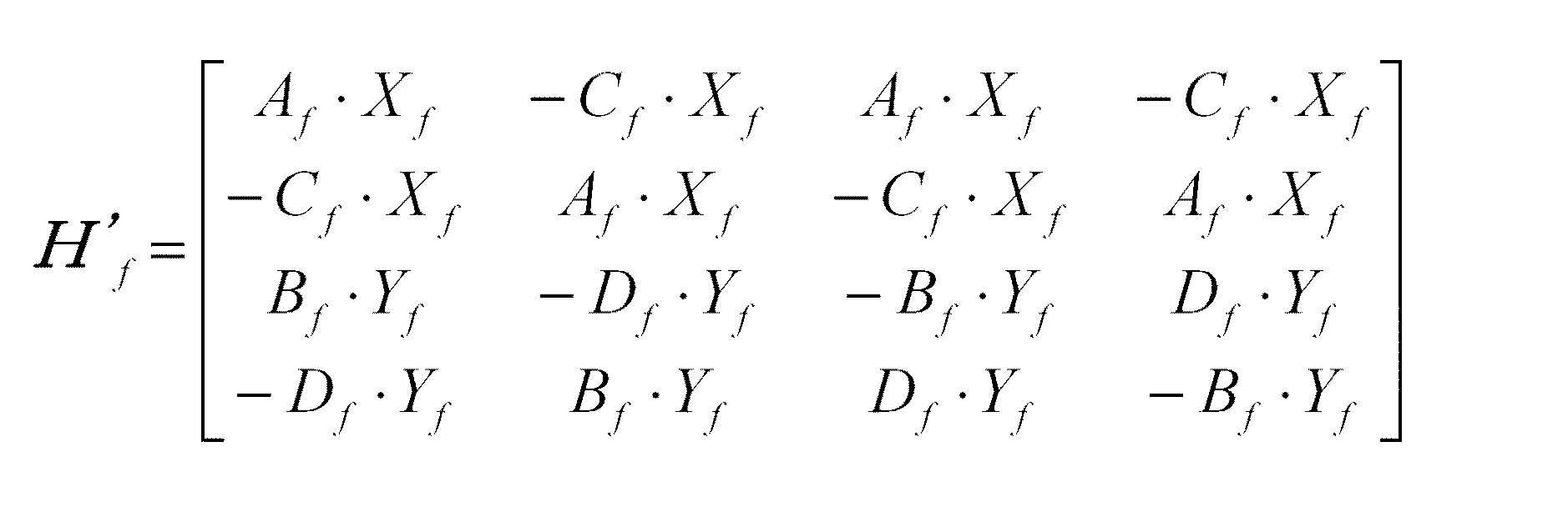
その後、逆ミックス部44は、第1復号部42に生成された第1信号と、第2復号部43に生成された第2信号とに対して係数テーブル46を用いた行列演算を行うことにより、マルチチャンネル信号を得る。ここで、係数テーブル46に配置されている係数は、上記第1の実施の形態で記述した行列の逆行列であり、たとえば4チャンネルの信号がダウンミックスされている場合では、
Thereafter, the
そして、周波数時間変換部45では、逆ミックス部44より出力された周波数領域のマルチチャンネル信号をそれぞれ、フーリエ変換や、離散コサイン変換や、サブバンドフィルタ等に代表される手法を用いて、時間領域のオーディオ信号に変換する。
Then, the frequency
上記のように、本実施の形態によれば、ビットストリームからダウンミックス符号および補助情報符号を抽出する逆多重化部41と、ダウンミックス信号と補助情報とからマルチチャンネル信号を生成する逆ミックス部44と、2チャンネルの係数がマルチチャンネル再生時の頭部伝達特性を模擬する行列の逆行列である係数テーブル46とを備え、逆ミックス部44が係数テーブル46を用いて、前記マルチチャンネル信号を生成することにより、ダウンミックス信号が伝達特性を含む信号であっても、元のマルチチャンネル信号を再生することができる。
As described above, according to the present embodiment, the
(第5の実施の形態)
以下、本発明の第5の実施の形態における音響信号復号装置の構成図を図6に示し、説明する。
(Fifth embodiment)
A configuration diagram of an acoustic signal decoding apparatus according to the fifth embodiment of the present invention will be described below with reference to FIG.
図6に示すように、音響信号復号装置50は、第1符号化信号と第2符号化信号とが多重化されたビットストリームから、ダウンミックス信号が符号化された第1符号化信号および補助情報が符号化された第2符号化信号を抽出する逆多重化部51と、前記第1符号化信号から2チャンネルの周波数領域のオーディオ信号であるダウンミックス信号を生成する第1復号部52と、前記第2符号化信号から補助情報を生成する第2復号部53と、前記ダウンミックス信号と前記補助情報とからマルチチャンネル信号を生成する逆ミックス部54と、前記ダウンミックス信号を出力するか前記マルチチャンネル信号を出力するかを切り替える出力チャンネル切替え部55と、前記出力チャンネル切替え部55に選択出力された信号から時間領域のオーディオ信号を生成する周波数時間変換部56と、2チャンネルの係数がマルチチャンネル再生時の頭部伝達特性を模擬するN×Nの正方行列の逆行列である係数テーブル57とを備えた構成である。
As shown in FIG. 6, the acoustic
以上のように構成された音響信号復号装置50の動作について、以下に説明する。
The operation of the acoustic
まず、逆多重化部51は、上記第1または第2の実施の形態に記載の音響信号符号化装置によって生成されたビットストリームから、第1符号化信号と第2符号化信号とをそれぞれ抽出する。
First, the
次に、第1復号部52は、逆多重化部51に抽出されたダウンミックス符号である第1符号化信号を復号して、2チャンネルのダウンミックス信号が周波数領域で記述されている第1信号を生成する。
Next, the
また、第2復号部53は、逆多重化部51に抽出された補助情報符号である第2符号化信号を復号して、前記第1信号からマルチチャンネル信号を生成する際に指標となる第2信号を生成する。
The
その後、逆ミックス部54は、第1復号部52に生成された第1信号と、第2復号部53に生成された第2信号とに対して係数テーブル57を用いた行列演算を行うことにより、マルチチャンネル信号を得る。ここで、係数テーブル57に配置されている係数は、上記第1の実施の形態で記述した行列の逆行列であり、たとえば4チャンネルの信号がダウンミックスされている場合では、
After that, the
さらに、出力チャンネル切替え部55では、第1復号部52より出力された周波数領域のダウンミックス信号を出力するか、逆ミックス部54より出力された周波数領域のマルチチャンネル信号を出力するかを切り替える。ここで、ダウンミックス信号を出力する場合、第2復号部53と逆ミックス部54と係数テーブル57の動作は停止させ、消費電力を削減することが望ましい。
Further, the output
そして、周波数時間変換部56では、出力チャンネル切替え部55に切り替えられ出力された周波数領域の信号を、それぞれ時間領域のオーディオ信号に変換する。
Then, the frequency /
上記のように、本実施の形態によれば、ビットストリームからダウンミックス符号および補助情報符号を抽出する逆多重化部51と、ダウンミックス信号と補助情報とからマルチチャンネル信号を生成する逆ミックス部54と、前記ダウンミックス信号を出力するか前記マルチチャンネル信号を出力するかを切り替える出力チャンネル切替え部55と、出力チャンネル切替え部55に出力選択された信号から時間領域のオーディオ信号を生成する周波数時間変換部56とを備えることにより、2チャンネルのダウンミックス信号の再生とマルチチャンネル信号の再生とを、共通の構成要素で実現することができる。
As described above, according to the present embodiment, the
以上のように、本発明にかかる音響信号符号化装置および音響信号復号装置は、ダウンミックス信号が所望の伝達関数のフィルタ処理された信号となり、第1符号化信号のみを再生した場合でも、マルチチャンネル信号の空間情報が反映され、且つ、第2符号化信号を用いることにより元のマルチチャンネル信号を再現することができるという効果を有し、マルチチャンネル信号を符号化する音響信号符号化装置および符号化された信号を復号する音響信号復号装置等として有用である。 As described above, in the acoustic signal encoding device and the acoustic signal decoding device according to the present invention, even when the downmix signal is a filtered signal of a desired transfer function and only the first encoded signal is reproduced, An acoustic signal encoding apparatus for encoding a multi-channel signal, which has an effect that the spatial information of the channel signal is reflected and the original multi-channel signal can be reproduced by using the second encoded signal, and It is useful as an acoustic signal decoding device or the like that decodes an encoded signal.
10、20 音響信号符号化装置
11、21 時間周波数変換部
12、22 第1信号出力部
13、23 第1符号化部
14、24 第2信号出力部
15、25 第2符号化部
16、29 多重化部
17、27 係数テーブル
26 係数テーブル選択部
28 第3符号化部
30、40、50 音響信号復号装置
31、41、51 逆多重化部
32 復号部
33、45、56 周波数時間変換部
42、52 第1復号部
43、53 第2復号部
44、54 逆ミックス部
46、57 係数テーブル
55 出力チャンネル切替え部
61 左前スピーカ
62 右前スピーカ
63 左後スピーカ
64 右後スピーカ
65 受聴者の頭部
70 音響信号復号装置
71 逆多重化部
72 第1復号部
73 第2復号部
74 逆ミックス部
75 周波数時間変換部
76 係数テーブル
77 頭部伝達関数模擬部
10, 20 Acoustic
Claims (5)
前記Nチャンネルの周波数領域信号を2チャンネルの信号にダウンミックスする第1信号出力手段と、
前記ダウンミックス信号をマルチチャンネル信号に戻すための補助情報を生成する第2信号出力手段と、
前記ダウンミックス信号を符号化し第1符号化信号を生成する第1符号化手段と、
前記補助情報を符号化し第2符号化信号を生成する第2符号化手段と、
前記第1符号化信号と前記第2符号化信号とを多重化する多重化手段と、
伝達特性を実現する係数が周波数毎に記述された係数テーブルとを備え、
前記係数テーブルは、N×Nの正方行列であり、2チャンネルの係数がマルチチャンネル再生時の頭部伝達特性を模擬するものであり、残りのチャンネルの係数は前記2チャンネルの係数を符号反転および並び替えした値によって構成され、
前記第1信号出力手段は、前記係数テーブルにしたがって前記Nチャンネルの周波数領域信号を前記2チャンネルの信号にダウンミックスし、
前記第2信号出力手段は、前記係数テーブルにしたがって前記ダウンミックス信号の前記補助情報を生成することを特徴とする音響信号符号化装置。 Time-frequency conversion means for converting three or more N-channel signals into the frequency domain;
First signal output means for downmixing the N-channel frequency domain signal into a 2-channel signal;
Second signal output means for generating auxiliary information for returning the downmix signal to a multi-channel signal;
First encoding means for encoding the downmix signal and generating a first encoded signal;
Second encoding means for encoding the auxiliary information and generating a second encoded signal;
Multiplexing means for multiplexing the first encoded signal and the second encoded signal;
A coefficient table in which coefficients for realizing transfer characteristics are described for each frequency;
The coefficient table is an N × N square matrix, the coefficients of the two channels simulate head-related transfer characteristics during multi-channel reproduction, and the coefficients of the remaining channels are obtained by inverting the sign of the coefficients of the two channels. Composed of sorted values,
The first signal output means downmixes the N-channel frequency domain signal into the two-channel signal according to the coefficient table,
The second signal output unit generates the auxiliary information of the downmix signal according to the coefficient table.
さらに、前記係数テーブルを用途に応じて選択する係数テーブル選択手段とを備え、
前記多重化手段は、前記第1符号化信号と前記第2符号化信号とともに、前記係数テーブル選択手段に選択された前記係数テーブルを示す指標を多重化することを特徴とする請求項1に記載の音響信号符号化装置。 A plurality of coefficient tables comprising coefficients that realize different transfer characteristics;
Furthermore, the coefficient table selecting means for selecting the coefficient table according to the application,
2. The multiplexing unit multiplexes an index indicating the coefficient table selected by the coefficient table selecting unit together with the first encoded signal and the second encoded signal. Acoustic signal encoding device.
前記ダウンミックス符号から2チャンネルの周波数領域のオーディオ信号を生成する復号手段と、
前記周波数領域のオーディオ信号から時間領域のオーディオ信号を生成する周波数時間変換手段とを備えたことを特徴とする音響信号復号装置。 Demultiplexing means for extracting only the downmix code from the bitstream generated by the acoustic signal encoding device according to claim 1 or 2,
Decoding means for generating a two-channel frequency domain audio signal from the downmix code;
An acoustic signal decoding apparatus comprising: a frequency time conversion unit that generates a time domain audio signal from the frequency domain audio signal.
前記ダウンミックス符号から2チャンネルの周波数領域のオーディオ信号であるダウンミックス信号を生成する第1の復号手段と、
前記補助情報符号から補助情報を生成する第2の復号手段と、
前記ダウンミックス信号と前記補助情報とからマルチチャンネル信号を生成する逆ミックス手段と、
前記マルチチャンネル信号から時間領域のオーディオ信号を生成する周波数時間変換手段と、
2チャンネルの係数がマルチチャンネル再生時の頭部伝達特性を模擬するN×Nの正方行列の逆行列である係数テーブルとを備え、
前記逆ミックス手段は、前記係数テーブルを用いて前記マルチチャンネル信号を生成することを特徴とする音響信号復号装置。 Demultiplexing means for extracting a downmix code and an auxiliary information code from the bitstream generated by the acoustic signal encoding device according to claim 1 or 2,
First decoding means for generating a downmix signal that is an audio signal in a frequency domain of two channels from the downmix code;
Second decoding means for generating auxiliary information from the auxiliary information code;
Reverse mix means for generating a multi-channel signal from the downmix signal and the auxiliary information;
Frequency time conversion means for generating a time domain audio signal from the multi-channel signal;
A coefficient table that is an inverse matrix of an N × N square matrix in which the coefficients of the two channels simulate the head-related transfer characteristics during multi-channel playback,
The acoustic signal decoding apparatus, wherein the inverse mix means generates the multi-channel signal using the coefficient table.
前記周波数時間変換手段は、前記出力チャンネル切替え手段に選択出力された信号から前記時間領域のオーディオ信号を生成することを特徴とした請求項4に記載の音響信号復号装置。 Output channel switching means for switching whether to output the downmix signal or the multi-channel signal,
5. The acoustic signal decoding apparatus according to claim 4, wherein the frequency time conversion unit generates the time domain audio signal from the signal selected and output to the output channel switching unit.
Priority Applications (4)
| Application Number | Priority Date | Filing Date | Title |
|---|---|---|---|
| JP2004175656A JP2005352396A (en) | 2004-06-14 | 2004-06-14 | Acoustic signal encoding apparatus and acoustic signal decoding apparatus |
| EP05748600A EP1768451A4 (en) | 2004-06-14 | 2005-06-13 | ACOUSTIC SIGNAL ENCODING DEVICE AND ACOUSTIC SIGNAL DECODING DEVICE |
| US11/570,471 US20080052089A1 (en) | 2004-06-14 | 2005-06-13 | Acoustic Signal Encoding Device and Acoustic Signal Decoding Device |
| PCT/JP2005/010811 WO2005122639A1 (en) | 2004-06-14 | 2005-06-13 | Acoustic signal encoding device and acoustic signal decoding device |
Applications Claiming Priority (1)
| Application Number | Priority Date | Filing Date | Title |
|---|---|---|---|
| JP2004175656A JP2005352396A (en) | 2004-06-14 | 2004-06-14 | Acoustic signal encoding apparatus and acoustic signal decoding apparatus |
Publications (1)
| Publication Number | Publication Date |
|---|---|
| JP2005352396A true JP2005352396A (en) | 2005-12-22 |
Family
ID=35503542
Family Applications (1)
| Application Number | Title | Priority Date | Filing Date |
|---|---|---|---|
| JP2004175656A Pending JP2005352396A (en) | 2004-06-14 | 2004-06-14 | Acoustic signal encoding apparatus and acoustic signal decoding apparatus |
Country Status (4)
| Country | Link |
|---|---|
| US (1) | US20080052089A1 (en) |
| EP (1) | EP1768451A4 (en) |
| JP (1) | JP2005352396A (en) |
| WO (1) | WO2005122639A1 (en) |
Cited By (16)
| Publication number | Priority date | Publication date | Assignee | Title |
|---|---|---|---|---|
| JP2007202021A (en) * | 2006-01-30 | 2007-08-09 | Sony Corp | Audio signal processing apparatus, audio signal processing system, program |
| WO2008018689A1 (en) * | 2006-08-09 | 2008-02-14 | Samsung Electronics Co., Ltd. | Method, medium, and system encoding/decoding a multi-channel audio signal, and method medium, and system decoding a down-mixed signal to a 2-channel signal |
| KR100830472B1 (en) | 2005-08-30 | 2008-05-20 | 엘지전자 주식회사 | Method and apparatus for decoding an audio signal |
| JP2008542815A (en) * | 2005-05-26 | 2008-11-27 | エルジー エレクトロニクス インコーポレイティド | Audio signal decoding method and apparatus |
| JP2009500659A (en) * | 2005-06-30 | 2009-01-08 | エルジー エレクトロニクス インコーポレイティド | Audio signal encoding and decoding method and apparatus |
| JP2009508157A (en) * | 2005-09-13 | 2009-02-26 | コーニンクレッカ フィリップス エレクトロニクス エヌ ヴィ | Audio encoding |
| JP2009524341A (en) * | 2006-01-19 | 2009-06-25 | エルジー エレクトロニクス インコーポレイティド | Media signal processing method and apparatus |
| JP2009526467A (en) * | 2006-02-09 | 2009-07-16 | エルジー エレクトロニクス インコーポレイティド | Method and apparatus for encoding and decoding object-based audio signal |
| JP2009527970A (en) * | 2006-02-21 | 2009-07-30 | コーニンクレッカ フィリップス エレクトロニクス エヌ ヴィ | Audio encoding and decoding |
| JP2010503887A (en) * | 2006-09-18 | 2010-02-04 | コーニンクレッカ フィリップス エレクトロニクス エヌ ヴィ | Audio object encoding and decoding |
| JP2011002574A (en) * | 2009-06-17 | 2011-01-06 | Nippon Hoso Kyokai <Nhk> | 3-dimensional sound encoding device, 3-dimensional sound decoding device, encoding program and decoding program |
| JP2011048279A (en) * | 2009-08-28 | 2011-03-10 | Nippon Hoso Kyokai <Nhk> | 3-dimensional sound encoding device, 3-dimensional sound decoding device, encoding program and decoding program |
| US8160258B2 (en) | 2006-02-07 | 2012-04-17 | Lg Electronics Inc. | Apparatus and method for encoding/decoding signal |
| JP2012123090A (en) * | 2010-12-07 | 2012-06-28 | Nippon Hoso Kyokai <Nhk> | Acoustic encoder and decoder, and program for the same |
| US8917874B2 (en) | 2005-05-26 | 2014-12-23 | Lg Electronics Inc. | Method and apparatus for decoding an audio signal |
| JP2018518875A (en) * | 2015-04-30 | 2018-07-12 | 華為技術有限公司Huawei Technologies Co.,Ltd. | Audio signal processing apparatus and method |
Families Citing this family (13)
| Publication number | Priority date | Publication date | Assignee | Title |
|---|---|---|---|---|
| DE102004043521A1 (en) * | 2004-09-08 | 2006-03-23 | Fraunhofer-Gesellschaft zur Förderung der angewandten Forschung e.V. | Device and method for generating a multi-channel signal or a parameter data set |
| DE102005010057A1 (en) * | 2005-03-04 | 2006-09-07 | Fraunhofer-Gesellschaft zur Förderung der angewandten Forschung e.V. | Apparatus and method for generating a coded stereo signal of an audio piece or audio data stream |
| JP4606507B2 (en) * | 2006-03-24 | 2011-01-05 | ドルビー インターナショナル アクチボラゲット | Spatial downmix generation from parametric representations of multichannel signals |
| CA2701457C (en) | 2007-10-17 | 2016-05-17 | Oliver Hellmuth | Audio coding using upmix |
| EP2215630B1 (en) | 2007-12-06 | 2016-03-02 | Lg Electronics Inc. | A method and an apparatus for processing an audio signal |
| JP5400059B2 (en) * | 2007-12-18 | 2014-01-29 | エルジー エレクトロニクス インコーポレイティド | Audio signal processing method and apparatus |
| US8620008B2 (en) * | 2009-01-20 | 2013-12-31 | Lg Electronics Inc. | Method and an apparatus for processing an audio signal |
| KR101187075B1 (en) * | 2009-01-20 | 2012-09-27 | 엘지전자 주식회사 | A method for processing an audio signal and an apparatus for processing an audio signal |
| US20100324915A1 (en) * | 2009-06-23 | 2010-12-23 | Electronic And Telecommunications Research Institute | Encoding and decoding apparatuses for high quality multi-channel audio codec |
| US9412385B2 (en) * | 2013-05-28 | 2016-08-09 | Qualcomm Incorporated | Performing spatial masking with respect to spherical harmonic coefficients |
| CN108701463B (en) * | 2016-02-03 | 2020-03-10 | 杜比国际公司 | Efficient Format Conversion in Audio Coding |
| CN110853658B (en) * | 2019-11-26 | 2021-12-07 | 中国电影科学技术研究所 | Method and apparatus for downmixing audio signal, computer device, and readable storage medium |
| CN116597847A (en) * | 2020-06-17 | 2023-08-15 | 瑞典爱立信有限公司 | Head-Related (HR) Filters |
Citations (8)
| Publication number | Priority date | Publication date | Assignee | Title |
|---|---|---|---|---|
| JPH06348295A (en) * | 1993-06-07 | 1994-12-22 | Sanyo Electric Co Ltd | Voice band dividing and decoding device |
| JPH0946799A (en) * | 1995-08-02 | 1997-02-14 | Toshiba Corp | Audio system, reproduction method, recording medium and recording method on recording medium |
| JPH09224300A (en) * | 1996-02-16 | 1997-08-26 | Sanyo Electric Co Ltd | Method and device for correcting sound image position |
| JPH10336796A (en) * | 1997-05-23 | 1998-12-18 | Deutsche Thomson Brandt Gmbh | Error masking method for multi-channel audio signal and device therefor |
| JPH1132400A (en) * | 1997-07-14 | 1999-02-02 | Matsushita Electric Ind Co Ltd | Digital signal playback device |
| JP2000156038A (en) * | 1998-11-16 | 2000-06-06 | Victor Co Of Japan Ltd | Voice encoding device, recording medium, voice decoding device, voice transmitting method, and computer recording medium |
| JP2001195096A (en) * | 1998-11-16 | 2001-07-19 | Victor Co Of Japan Ltd | Voice coder |
| JP2002217841A (en) * | 2001-01-15 | 2002-08-02 | Sony Corp | Audio signal reproducing apparatus and method |
Family Cites Families (4)
| Publication number | Priority date | Publication date | Assignee | Title |
|---|---|---|---|---|
| US5438623A (en) * | 1993-10-04 | 1995-08-01 | The United States Of America As Represented By The Administrator Of National Aeronautics And Space Administration | Multi-channel spatialization system for audio signals |
| US5912976A (en) * | 1996-11-07 | 1999-06-15 | Srs Labs, Inc. | Multi-channel audio enhancement system for use in recording and playback and methods for providing same |
| US6757659B1 (en) * | 1998-11-16 | 2004-06-29 | Victor Company Of Japan, Ltd. | Audio signal processing apparatus |
| WO2006126843A2 (en) * | 2005-05-26 | 2006-11-30 | Lg Electronics Inc. | Method and apparatus for decoding audio signal |
-
2004
- 2004-06-14 JP JP2004175656A patent/JP2005352396A/en active Pending
-
2005
- 2005-06-13 US US11/570,471 patent/US20080052089A1/en not_active Abandoned
- 2005-06-13 EP EP05748600A patent/EP1768451A4/en not_active Withdrawn
- 2005-06-13 WO PCT/JP2005/010811 patent/WO2005122639A1/en not_active Ceased
Patent Citations (8)
| Publication number | Priority date | Publication date | Assignee | Title |
|---|---|---|---|---|
| JPH06348295A (en) * | 1993-06-07 | 1994-12-22 | Sanyo Electric Co Ltd | Voice band dividing and decoding device |
| JPH0946799A (en) * | 1995-08-02 | 1997-02-14 | Toshiba Corp | Audio system, reproduction method, recording medium and recording method on recording medium |
| JPH09224300A (en) * | 1996-02-16 | 1997-08-26 | Sanyo Electric Co Ltd | Method and device for correcting sound image position |
| JPH10336796A (en) * | 1997-05-23 | 1998-12-18 | Deutsche Thomson Brandt Gmbh | Error masking method for multi-channel audio signal and device therefor |
| JPH1132400A (en) * | 1997-07-14 | 1999-02-02 | Matsushita Electric Ind Co Ltd | Digital signal playback device |
| JP2000156038A (en) * | 1998-11-16 | 2000-06-06 | Victor Co Of Japan Ltd | Voice encoding device, recording medium, voice decoding device, voice transmitting method, and computer recording medium |
| JP2001195096A (en) * | 1998-11-16 | 2001-07-19 | Victor Co Of Japan Ltd | Voice coder |
| JP2002217841A (en) * | 2001-01-15 | 2002-08-02 | Sony Corp | Audio signal reproducing apparatus and method |
Cited By (39)
| Publication number | Priority date | Publication date | Assignee | Title |
|---|---|---|---|---|
| US9595267B2 (en) | 2005-05-26 | 2017-03-14 | Lg Electronics Inc. | Method and apparatus for decoding an audio signal |
| JP2008542815A (en) * | 2005-05-26 | 2008-11-27 | エルジー エレクトロニクス インコーポレイティド | Audio signal decoding method and apparatus |
| US8917874B2 (en) | 2005-05-26 | 2014-12-23 | Lg Electronics Inc. | Method and apparatus for decoding an audio signal |
| US8214221B2 (en) | 2005-06-30 | 2012-07-03 | Lg Electronics Inc. | Method and apparatus for decoding an audio signal and identifying information included in the audio signal |
| JP2009500659A (en) * | 2005-06-30 | 2009-01-08 | エルジー エレクトロニクス インコーポレイティド | Audio signal encoding and decoding method and apparatus |
| KR100830472B1 (en) | 2005-08-30 | 2008-05-20 | 엘지전자 주식회사 | Method and apparatus for decoding an audio signal |
| JP2009508157A (en) * | 2005-09-13 | 2009-02-26 | コーニンクレッカ フィリップス エレクトロニクス エヌ ヴィ | Audio encoding |
| JP2009524336A (en) * | 2006-01-19 | 2009-06-25 | エルジー エレクトロニクス インコーポレイティド | Media signal processing method and apparatus |
| JP2009524340A (en) * | 2006-01-19 | 2009-06-25 | エルジー エレクトロニクス インコーポレイティド | Media signal processing method and apparatus |
| JP2009524341A (en) * | 2006-01-19 | 2009-06-25 | エルジー エレクトロニクス インコーポレイティド | Media signal processing method and apparatus |
| US8521313B2 (en) | 2006-01-19 | 2013-08-27 | Lg Electronics Inc. | Method and apparatus for processing a media signal |
| US8488819B2 (en) | 2006-01-19 | 2013-07-16 | Lg Electronics Inc. | Method and apparatus for processing a media signal |
| US8411869B2 (en) | 2006-01-19 | 2013-04-02 | Lg Electronics Inc. | Method and apparatus for processing a media signal |
| JP4814343B2 (en) * | 2006-01-19 | 2011-11-16 | エルジー エレクトロニクス インコーポレイティド | Media signal processing method and apparatus |
| US8351611B2 (en) | 2006-01-19 | 2013-01-08 | Lg Electronics Inc. | Method and apparatus for processing a media signal |
| US8208641B2 (en) | 2006-01-19 | 2012-06-26 | Lg Electronics Inc. | Method and apparatus for processing a media signal |
| JP2007202021A (en) * | 2006-01-30 | 2007-08-09 | Sony Corp | Audio signal processing apparatus, audio signal processing system, program |
| US8638945B2 (en) | 2006-02-07 | 2014-01-28 | Lg Electronics, Inc. | Apparatus and method for encoding/decoding signal |
| US9626976B2 (en) | 2006-02-07 | 2017-04-18 | Lg Electronics Inc. | Apparatus and method for encoding/decoding signal |
| US8285556B2 (en) | 2006-02-07 | 2012-10-09 | Lg Electronics Inc. | Apparatus and method for encoding/decoding signal |
| US8296156B2 (en) | 2006-02-07 | 2012-10-23 | Lg Electronics, Inc. | Apparatus and method for encoding/decoding signal |
| US8160258B2 (en) | 2006-02-07 | 2012-04-17 | Lg Electronics Inc. | Apparatus and method for encoding/decoding signal |
| US8712058B2 (en) | 2006-02-07 | 2014-04-29 | Lg Electronics, Inc. | Apparatus and method for encoding/decoding signal |
| US8625810B2 (en) | 2006-02-07 | 2014-01-07 | Lg Electronics, Inc. | Apparatus and method for encoding/decoding signal |
| US8612238B2 (en) | 2006-02-07 | 2013-12-17 | Lg Electronics, Inc. | Apparatus and method for encoding/decoding signal |
| JP2009526467A (en) * | 2006-02-09 | 2009-07-16 | エルジー エレクトロニクス インコーポレイティド | Method and apparatus for encoding and decoding object-based audio signal |
| US9865270B2 (en) | 2006-02-21 | 2018-01-09 | Koninklijke Philips N.V. | Audio encoding and decoding |
| JP2009527970A (en) * | 2006-02-21 | 2009-07-30 | コーニンクレッカ フィリップス エレクトロニクス エヌ ヴィ | Audio encoding and decoding |
| US9009057B2 (en) | 2006-02-21 | 2015-04-14 | Koninklijke Philips N.V. | Audio encoding and decoding to generate binaural virtual spatial signals |
| US10741187B2 (en) | 2006-02-21 | 2020-08-11 | Koninklijke Philips N.V. | Encoding of multi-channel audio signal to generate encoded binaural signal, and associated decoding of encoded binaural signal |
| US12165656B2 (en) | 2006-02-21 | 2024-12-10 | Koninklijke Philips N.V. | Encoding of a multi-channel audio signal to generate binaural signal and decoding of an encoded binauralsignal |
| US8867751B2 (en) | 2006-08-09 | 2014-10-21 | Samsung Electronics Co., Ltd. | Method, medium, and system encoding/decoding a multi-channel audio signal, and method medium, and system decoding a down-mixed signal to a 2-channel signal |
| WO2008018689A1 (en) * | 2006-08-09 | 2008-02-14 | Samsung Electronics Co., Ltd. | Method, medium, and system encoding/decoding a multi-channel audio signal, and method medium, and system decoding a down-mixed signal to a 2-channel signal |
| JP2010503887A (en) * | 2006-09-18 | 2010-02-04 | コーニンクレッカ フィリップス エレクトロニクス エヌ ヴィ | Audio object encoding and decoding |
| JP2011002574A (en) * | 2009-06-17 | 2011-01-06 | Nippon Hoso Kyokai <Nhk> | 3-dimensional sound encoding device, 3-dimensional sound decoding device, encoding program and decoding program |
| JP2011048279A (en) * | 2009-08-28 | 2011-03-10 | Nippon Hoso Kyokai <Nhk> | 3-dimensional sound encoding device, 3-dimensional sound decoding device, encoding program and decoding program |
| JP2012123090A (en) * | 2010-12-07 | 2012-06-28 | Nippon Hoso Kyokai <Nhk> | Acoustic encoder and decoder, and program for the same |
| JP2018518875A (en) * | 2015-04-30 | 2018-07-12 | 華為技術有限公司Huawei Technologies Co.,Ltd. | Audio signal processing apparatus and method |
| US10600426B2 (en) | 2015-04-30 | 2020-03-24 | Huawei Technologies Co., Ltd. | Audio signal processing apparatuses and methods |
Also Published As
| Publication number | Publication date |
|---|---|
| EP1768451A1 (en) | 2007-03-28 |
| WO2005122639A1 (en) | 2005-12-22 |
| US20080052089A1 (en) | 2008-02-28 |
| EP1768451A4 (en) | 2009-02-25 |
Similar Documents
| Publication | Publication Date | Title |
|---|---|---|
| JP2005352396A (en) | Acoustic signal encoding apparatus and acoustic signal decoding apparatus | |
| CN101326726B (en) | System and method for encoding/decoding multi-channel audio signal | |
| JP5455647B2 (en) | Audio decoder | |
| JP5081838B2 (en) | Audio encoding and decoding | |
| JP6288100B2 (en) | Audio encoding apparatus and audio decoding apparatus | |
| RU2327304C2 (en) | Compatible multichannel coding/decoding | |
| KR100754220B1 (en) | Binaural decoder for MPE surround and its decoding method | |
| KR101102401B1 (en) | Method for encoding and decoding object-based audio signal and apparatus thereof | |
| KR101342425B1 (en) | A method for applying reverb to a multi-channel downmixed audio input signal and a reverberator configured to apply reverb to an multi-channel downmixed audio input signal | |
| CN104681030B (en) | Apparatus and method for encoding/decoding signal | |
| KR101158698B1 (en) | A multi-channel encoder, a method of encoding input signals, storage medium, and a decoder operable to decode encoded output data | |
| CN101379553B (en) | Apparatus and method for encoding/decoding signal | |
| KR100636145B1 (en) | Exednded high resolution audio signal encoder and decoder thereof | |
| JP2005521921A (en) | Signal processing | |
| JP5483813B2 (en) | Multi-channel speech / acoustic signal encoding apparatus and method, and multi-channel speech / acoustic signal decoding apparatus and method | |
| KR20070081735A (en) | Method and apparatus for encoding / decoding audio signal |
Legal Events
| Date | Code | Title | Description |
|---|---|---|---|
| A621 | Written request for application examination |
Free format text: JAPANESE INTERMEDIATE CODE: A621 Effective date: 20070306 |
|
| A131 | Notification of reasons for refusal |
Free format text: JAPANESE INTERMEDIATE CODE: A131 Effective date: 20090728 |
|
| A02 | Decision of refusal |
Free format text: JAPANESE INTERMEDIATE CODE: A02 Effective date: 20091124 |