JP2005343036A - Ink remaining amount detection module for ink jet recording, ink tank including the ink remaining amount detecting module, and ink jet recording apparatus - Google Patents
Ink remaining amount detection module for ink jet recording, ink tank including the ink remaining amount detecting module, and ink jet recording apparatus Download PDFInfo
- Publication number
- JP2005343036A JP2005343036A JP2004165888A JP2004165888A JP2005343036A JP 2005343036 A JP2005343036 A JP 2005343036A JP 2004165888 A JP2004165888 A JP 2004165888A JP 2004165888 A JP2004165888 A JP 2004165888A JP 2005343036 A JP2005343036 A JP 2005343036A
- Authority
- JP
- Japan
- Prior art keywords
- ink
- remaining amount
- information
- ink tank
- detection module
- Prior art date
- Legal status (The legal status is an assumption and is not a legal conclusion. Google has not performed a legal analysis and makes no representation as to the accuracy of the status listed.)
- Pending
Links
Images


Classifications
-
- B—PERFORMING OPERATIONS; TRANSPORTING
- B41—PRINTING; LINING MACHINES; TYPEWRITERS; STAMPS
- B41J—TYPEWRITERS; SELECTIVE PRINTING MECHANISMS, i.e. MECHANISMS PRINTING OTHERWISE THAN FROM A FORME; CORRECTION OF TYPOGRAPHICAL ERRORS
- B41J2/00—Typewriters or selective printing mechanisms characterised by the printing or marking process for which they are designed
- B41J2/005—Typewriters or selective printing mechanisms characterised by the printing or marking process for which they are designed characterised by bringing liquid or particles selectively into contact with a printing material
- B41J2/01—Ink jet
- B41J2/17—Ink jet characterised by ink handling
- B41J2/175—Ink supply systems ; Circuit parts therefor
- B41J2/17566—Ink level or ink residue control
-
- B—PERFORMING OPERATIONS; TRANSPORTING
- B41—PRINTING; LINING MACHINES; TYPEWRITERS; STAMPS
- B41J—TYPEWRITERS; SELECTIVE PRINTING MECHANISMS, i.e. MECHANISMS PRINTING OTHERWISE THAN FROM A FORME; CORRECTION OF TYPOGRAPHICAL ERRORS
- B41J2/00—Typewriters or selective printing mechanisms characterised by the printing or marking process for which they are designed
- B41J2/005—Typewriters or selective printing mechanisms characterised by the printing or marking process for which they are designed characterised by bringing liquid or particles selectively into contact with a printing material
- B41J2/01—Ink jet
- B41J2/17—Ink jet characterised by ink handling
- B41J2/175—Ink supply systems ; Circuit parts therefor
- B41J2/17503—Ink cartridges
- B41J2/17553—Outer structure
Landscapes
- Ink Jet (AREA)
Abstract
【課題】小型のインクタンクにも適用できるよう簡便な構成でインクタンク内のインクに関する情報を検出することができ、しかも検出した情報を簡便割確実に格納可能とする。
【解決手段】インク残量検出モジュール20は、支持基板21と支持基板21の第1の面21bに設けられた情報記憶素子22と、支持基板21の第2の面21cに設けられた外部コンタクト電極24とを有する。支持基板21には、その第1の面21bから第2の面21cへ貫通する2つの貫通穴21aが形成されている。支持基板21の第1の面21bには、情報記憶素子22および貫通穴21aを覆う封止構造体23が設けられる。封止構造体23は、光を透過する部材でプリズム形状に形成されている。インク残量検出モジュール20は、封止構造体23をインク収容室6内に露出させて、インクタンクの筐体の一部を構成するカップ部2に取り付けられる。
【選択図】図2Information relating to ink in an ink tank can be detected with a simple configuration so as to be applicable to a small ink tank, and the detected information can be stored easily and reliably.
An ink remaining amount detecting module includes a support substrate, an information storage element provided on a first surface of the support substrate, and an external contact provided on a second surface of the support substrate. And an electrode 24. The support substrate 21 is formed with two through holes 21a penetrating from the first surface 21b to the second surface 21c. A sealing structure 23 that covers the information storage element 22 and the through hole 21 a is provided on the first surface 21 b of the support substrate 21. The sealing structure 23 is a member that transmits light and is formed in a prism shape. The ink remaining amount detection module 20 is attached to the cup portion 2 that constitutes a part of the casing of the ink tank with the sealing structure 23 exposed in the ink storage chamber 6.
[Selection] Figure 2
Description
本発明は、インクジェット記録において、インクジェット記録ヘッドに供給するインクを収容するインクタンク内のインク残量を検出するのに用いられるインク残量検出モジュール、このインク残量検出モジュールを備えたインクタンク、およびインクジェット記録装置に関する。 The present invention relates to an ink remaining amount detection module used for detecting an ink remaining amount in an ink tank that stores ink to be supplied to an ink jet recording head in ink jet recording, an ink tank including the ink remaining amount detection module, And an ink jet recording apparatus.
インクジェット記録には、インクを吐出する記録ヘッドと、記録ヘッドに供給するインクを収容するインクタンクとが少なくとも用いられる。インクは消耗品であるので、インクジェット記録装置においては、インクタンクを単体で、あるいは記録ヘッドと一体としたカートリッジ形態でインクジェット記録装置に着脱自在とし、インクタンク内のインクがなくなったら新たなインクタンクに交換できるように構成されている。 In the inkjet recording, at least a recording head that discharges ink and an ink tank that stores ink to be supplied to the recording head are used. Since ink is a consumable item, in the ink jet recording apparatus, the ink tank can be detachably attached to the ink jet recording apparatus in the form of a single unit or a cartridge integrated with the recording head, and when the ink in the ink tank runs out, a new ink tank It is configured to be replaceable.
従来のインクジェット記録装置においては、インクタンクの交換時期をユーザに知らせるために、インクタンク内のインクの有無を検出する技術が提案され、かつ実用に供されている。インクの有無を検知する方法としては、
(1)インクタンク内に一対の電極を設け、インクを介して電極間に電流が流れることを利用して、インクが所定のレベル(インク液面の高さ)に達したことを検出する方法、
(2)インクタンクの内壁面にインクの屈折率に近いプリズムを設け、プリズムに向けて光を入射したときの、インクの液面位置がプリズムの位置よりも高い場合と低い場合での光の屈折の違いを利用して、インクが所定のレベルに達したことを検出する方法、
(3)インクタンク内のインクと、インクタンクの外部に設けた電極との間の静電容量の変化を利用して、インクが所定のレベルに達したことを検出する方法、
などが挙げられる。また、これらの方法を組み合わせたり、インクの吐出回数等からインクの使用量を換算するドットカウント法と呼ばれる方法と組み合わせたりすることも行われている。
In a conventional ink jet recording apparatus, a technique for detecting the presence or absence of ink in an ink tank has been proposed and put into practical use in order to inform the user of the time to replace the ink tank. As a method of detecting the presence or absence of ink,
(1) A method for detecting that the ink has reached a predetermined level (the height of the ink surface) by using a pair of electrodes in the ink tank and using a current flowing between the electrodes via the ink. ,
(2) A prism close to the refractive index of the ink is provided on the inner wall surface of the ink tank, and when the light is incident on the prism, the ink level is higher or lower than that of the prism. A method for detecting that the ink has reached a predetermined level by utilizing the difference in refraction;
(3) A method for detecting that the ink has reached a predetermined level by using a change in capacitance between the ink in the ink tank and an electrode provided outside the ink tank,
Etc. Further, these methods are combined or combined with a method called a dot count method for converting the amount of ink used from the number of ink ejections.
以下に、上述した各方法のうち、光学的にインクの残量を検出する従来の検出システムの一例について図10(a)〜(c)を参照して説明する。 Hereinafter, an example of a conventional detection system that optically detects the remaining amount of ink among the above-described methods will be described with reference to FIGS.
図10(a)に、光学的にインク残量を検出する手段を備えた従来のインクタンク101の断面図を示す。また、図10(b)に、このインクタンク101のカップ部102の斜視図を示す。
FIG. 10A is a cross-sectional view of a
インクタンク101は、カップ部102と蓋部103とを有し、これらで構成される筐体104内にインクを収容している。筐体104の内部は、下部に連通部109を有しカップ部102に形成された仕切壁114によって2つの空間に仕切られている。一方の空間は、連通部109を除いて密閉されインクを直接収容するインク収容室106である。他方の空間は、インクを吸収して保持する負圧発生部材111を収納する負圧発生部材収納室105である。負圧発生部材収納室105を形成する壁面には、記録ヘッド部(不図示)にインクを供給するためのインク供給口110と、インクの消費に伴って外部からインクタンク101内へ大気を導入するための大気連通口108とが形成されている。図10(a)において、負圧発生部材111がインクを保持している領域を斜線で示している。
The
仕切壁114の負圧発生部材収納室105側の壁面には、負圧発生部材収納室105からインク収容室106への大気導入を促進するための構造として、連通部109から上向きに延びる気体導入溝119が形成されている。また、負圧発生部材収納室105の内部において、大気連通口108の周囲は、負圧発生部材111が存在しない空間(バッファ部)となっている。
As a structure for accelerating the introduction of the atmosphere from the negative pressure generating
記録ヘッド部により負圧発生部材111のインクが消費され、負圧発生部材収納室105内の気液界面111aが図10(a)に示した気体導入溝119の上端に達すると、以後のインク消費に伴って大気連通口108から負圧発生部材収納室105内に空気が導入され、導入された空気は連通部109を通じてインク収容室106に入る。これに替わって、インク収容室106内のインクが、連通部109を通じて負圧発生部材収納室105に入り、負圧発生部材111に充填される。この動作を、気液交換動作という。
When the ink of the negative
したがって、記録ヘッド部により負圧発生部材収納室105内のインクが消費されても、その消費量に見合う分のインクがインク収容室106から負圧発生部材111に充填され、負圧発生部材収納室105内での気液界面111aがほぼ一定の高さに維持される。つまり、負圧発生部材111はほぼ一定量のインクを保持しており、それによって、記録ヘッド部に対する負圧がほぼ一定に保たれ、記録ヘッド部へのインク供給が安定する。
Therefore, even if the ink in the negative pressure generating
インク収容室106の底面には、カップ部102と一体に形成され頂点の角度を90°とした三角プリズム状の光学反射体113が配置されている。一方、インクタンク101が装着されるインクジェット記録装置(不図示)側においては、図10(c)に示すように、発光部152と受光部153とを有する光学センサーモジュール151が、光学反射体113の下方に配置されている。
On the bottom surface of the
インク収容室106内にインクがない場合は、図10(c)に実線矢印で示すように、発光部152から出射した光は、光学反射体113に入射し、その2つの斜面でそれぞれ反射して受光部153へ戻る。発光部152から出射した光の、光学反射体113の斜面への入射位置よりも高い位置までインクが存在している場合は、破線矢印で示すように、発光部152から出射して光学反射体113に入射した光は、その大部分が光学反射体113を透過する。したがって、受光部153に戻る光の強度によってインクの有り無しを検出することができる。
When there is no ink in the
上述した、光学的なインク残量検出手段を有するインクタンクの構成は特許文献1にも開示されている。 The configuration of the ink tank having the optical ink remaining amount detecting means described above is also disclosed in Patent Document 1.
ところで、近年のインクジェット記録装置はフルカラー化が進み、それに伴って使用するインクの色も多色化の傾向にある。そのため、インクジェット記録装置に搭載するインクタンクの種類も多くなってきており、インクタンクの誤装着を防止するために、インクタンクに固有の情報を持たせることも行われている。インクタンクに固有の情報を持たせるためには、機械的なID構造をインクタンクに設けたり、バーコードラベルをインクタンクに貼り付けたり、ROMなどの情報格納素子をインクタンクに設けたりすることが知られている。
上述のように、従来のインクジェット記録装置においては、高品位記録の要求から多色化が進みそれに伴って搭載するインクタンクの種類も多くなってきている。その一方で、設置面積をできるだけ小さくしたい、あるいはモバイルユースにおいて携帯性を向上したいという観点から、小型化の要求も高い。インクジェット記録装置の小型化が進むと、インクタンクの小型化も要求され、さらにはインク残量検出手段も簡便な構造であることが要求される。 As described above, in the conventional ink jet recording apparatus, the number of colors is increasing due to the demand for high quality recording, and the types of ink tanks to be mounted are increasing. On the other hand, there is a high demand for miniaturization from the viewpoint of reducing the installation area as much as possible or improving portability in mobile use. As the ink jet recording apparatus is further downsized, the ink tank is also required to be downsized, and the ink remaining amount detecting means is also required to have a simple structure.
また、従来は、検出したインクの残量に関する情報は、インクジェット記録装置へ送られ、インクジェット記録装置側からユーザにインクタンク交換のための警告を発している。前述したように、インクタンク固有の情報を持たせたインクタンクもあるが、この情報はあくまでも、収容しているインクの種類といった、インクタンクの誤装着を防止するのに必要な情報である。 Conventionally, information about the remaining amount of detected ink is sent to the ink jet recording apparatus, and a warning for ink tank replacement is issued to the user from the ink jet recording apparatus side. As described above, there is an ink tank having information unique to the ink tank. However, this information is information necessary to prevent erroneous mounting of the ink tank, such as the type of ink stored.
しかしながら、従来、インクに関する情報を簡便な構造で検出可能であり、しかも検出した情報を簡便かつ確実にインクタンクに格納できる技術はなかった。 However, conventionally, there has been no technique that can detect information related to ink with a simple structure and can store the detected information in an ink tank easily and reliably.
そこで本発明は、小型のインクタンクにも適用できるよう簡便な構成でインクタンク内に収容されたインクに関する情報を検出でき、しかも検出した情報を簡便かつ確実に格納可能とすることを目的とする。 SUMMARY OF THE INVENTION Accordingly, it is an object of the present invention to be able to detect information related to ink contained in an ink tank with a simple configuration so that it can be applied to a small ink tank, and to make it possible to store the detected information easily and reliably. .
上記目的を達成するため本発明のインク残量検出モジュールは、インクジェット記録に用いられるインクタンク内のインク残量を検出するために前記インクタンクに取り付けられるインク残量検出モジュールであって、第1の面およびその反対側の第2の面を有し、前記第1の面から前記第2の面へ貫通する2つの貫通穴が形成された支持基板と、前記支持基板の第1の面に設けられた、情報の書き込みおよび読み出しが可能な不揮発性の情報記憶手段と、前記支持基板の第1の面に、前記情報記憶手段および前記2つの貫通穴を覆い、かつ少なくとも前記2つの貫通穴を覆う部位が光を透過する部材でプリズム形状に形成された、前記情報記憶手段を封止する封止構造体と、前記支持基板に設けられた、インク残量に関する情報を前記情報記憶手段に書き込むために外部から伝達し、かつ前記情報記憶手段に書き込まれた情報を外部へ伝達するための情報伝達手段とを有する。 In order to achieve the above object, an ink remaining amount detecting module according to the present invention is an ink remaining amount detecting module attached to an ink tank for detecting an ink remaining amount in an ink tank used for ink jet recording. And a second substrate on the opposite side, and a support substrate in which two through holes penetrating from the first surface to the second surface are formed, and a first surface of the support substrate Non-volatile information storage means for writing and reading information provided, and covering the information storage means and the two through holes on the first surface of the support substrate, and at least the two through holes The information covering the information on the remaining amount of ink provided on the supporting substrate and the sealing structure for sealing the information storage means, the portion covering the surface being formed in a prism shape with a light transmitting member Transmitted from the outside to write the 憶 means, and having an information transmission means for transmitting the information written in the information storage unit to the outside.
また本発明のインク残量検出モジュールは、インクジェット記録に用いられるインクタンク内のインク残量を検出するために前記インクタンクに取り付けられるインク残量検出モジュールであって、第1の面およびその反対側の第2の面を有し、光を透過する部材からなる支持基板と、前記支持基板の第1の面に設けられた、情報の書き込みおよび読み出しが可能な不揮発性の情報記憶手段と、前記支持基板の第1の面に、前記情報記憶手段を覆い、かつ少なくとも一部が光を透過する部材でプリズム形状に形成された、前記情報記憶手段を封止する封止構造体と、前記支持基板に設けられた、インク残量に関する情報を前記情報記憶手段に書き込むために外部から伝達し、かつ前記情報記憶手段に書き込まれた情報を外部へ伝達するための情報伝達手段とを有する。 An ink remaining amount detecting module according to the present invention is an ink remaining amount detecting module attached to the ink tank for detecting the remaining amount of ink in the ink tank used for ink jet recording. A support substrate having a second surface on the side and made of a light transmitting member, and a non-volatile information storage means provided on the first surface of the support substrate capable of writing and reading information; A sealing structure for sealing the information storage means, which is formed on the first surface of the support substrate so as to cover the information storage means, and at least part of which is formed in a prism shape with a member that transmits light; Provided from the outside for writing information on the remaining amount of ink provided on the support substrate to the information storage means, and for transmitting the information written in the information storage means to the outside And a broadcast transmission means.
本発明のインク残量検出モジュールによれば、情報記憶手段および情報伝達手段が支持基板に設けられており、しかも情報記憶手段をインクや気体と直接接触しないように封止する封止構造体の少なくとも一部をプリズム形状として、インク残量を光学的に検出するための機能を持たせているので、小型のインクタンクに取り付けるのにも適した、コンパクトでかつ構成が簡易なインク残量検出モジュールが達成される。しかも不揮発性の情報記憶手段を有しているので、インク残量に関する情報を、簡便かつ確実にインク残量検出モジュール自身に格納することが可能である。 According to the ink remaining amount detection module of the present invention, the information storage means and the information transmission means are provided on the support substrate, and the sealing structure for sealing the information storage means so as not to come into direct contact with ink or gas. At least a part of the prism is shaped to provide a function for optically detecting the remaining amount of ink, so it is suitable for mounting on a small ink tank and is compact and easy to configure. Module is achieved. In addition, since the non-volatile information storage means is provided, it is possible to store information relating to the ink remaining amount in the ink remaining amount detecting module itself easily and reliably.
本発明のインクタンクは、インクを内部に収容するためのインク室と、該インク室内のインクを記録ヘッドに供給するためのインク供給口とを有するインクタンクにおいて、上記本発明のインク残量検出モジュールと、前記インク室の外壁および前記インク供給口を構成する筐体部材とを有し、前記インク残量検出モジュールは、前記封止構造体を前記インク室に露出させ、かつ前記支持基板の第2の面を外表面に露出させて、前記筐体部材に取り付けられていることを特徴とする。 The ink tank of the present invention is an ink tank having an ink chamber for containing ink therein and an ink supply port for supplying ink in the ink chamber to a recording head. A module, and a housing member constituting the outer wall of the ink chamber and the ink supply port, the ink remaining amount detecting module exposing the sealing structure to the ink chamber, and The second surface is exposed to the outer surface and is attached to the housing member.
本発明のインクタンクによれば、上述した本発明のインク残量検出モジュールが取り付けられているので、インクタンクの小型化が阻害されることなく、インク残量を検出し、かつ、インク残量に関する情報をインクタンク自身に持つことが可能である。 According to the ink tank of the present invention, since the ink remaining amount detecting module of the present invention described above is attached, the remaining amount of ink is detected and the ink remaining amount is detected without hindering the downsizing of the ink tank. Information about the ink tank itself.
本発明のインクジェット記録装置は、上記本発明のインクタンクを着脱可能に搭載し、前記インクタンクから供給されたインクを吐出する記録ヘッドを用いて記録媒体に記録を行うインクジェット記録装置であって、前記インクタンクを着脱可能に保持する保持部と、前記保持部に保持された前記インクタンクの前記インク残量検出モジュールに向けて光を出射する光学センサと、前記インクタンクに取り付けられた前記インク残量検出モジュールの前記情報伝達手段を介して前記インク残量検出モジュールとの間で情報のやり取りを行うための装置側情報伝達手段を有する。 An ink jet recording apparatus according to the present invention is an ink jet recording apparatus in which the ink tank according to the present invention is detachably mounted, and recording is performed on a recording medium using a recording head that discharges ink supplied from the ink tank. A holding unit that detachably holds the ink tank, an optical sensor that emits light toward the ink remaining amount detection module of the ink tank held by the holding unit, and the ink attached to the ink tank And a device-side information transmission unit for exchanging information with the ink remaining amount detection module via the information transmission unit of the remaining amount detection module.
本発明のインクジェット記録装置によれば、上述した本発明のインクタンクが搭載され、そのインクタンクに取り付けられたインク残量検出モジュールとの間で情報のやり取りを行うための装置側情報伝達手段を有しているので、インクジェット記録装置は、その動作をインク残量検出モジュールを利用して得られた情報に基づいて制御したり、インクタンクのインク残量に関する情報をインクタンク自身に持たせたりすることが可能となる。 According to the ink jet recording apparatus of the present invention, the apparatus-side information transmission means for mounting the above-described ink tank of the present invention and exchanging information with the ink remaining amount detecting module attached to the ink tank is provided. Therefore, the ink jet recording apparatus controls the operation based on information obtained by using the ink remaining amount detecting module, or causes the ink tank itself to have information on the ink remaining amount of the ink tank. It becomes possible to do.
本発明のインクタンクの製造方法は、インクを内部に収容したインク室と、該インク室内のインクを記録ヘッドに供給するためのインク供給口とを有するインクタンクの製造方法において、前記インク室の外壁および前記インク供給口を構成し、かつ、上記本発明のインク残量検出モジュールのいずれか一方が前記封止構造体を前記インク室に露出させて取り付けられた筐体部材を用意する工程と、前記インク室内にインクを充填する工程と、前記インク残量検出モジュールの前記情報記憶手段に、インク有りを意味する情報を書き込む工程とを有する。 An ink tank manufacturing method according to the present invention is an ink tank manufacturing method comprising: an ink chamber containing ink therein; and an ink supply port for supplying ink in the ink chamber to a recording head. A step of preparing a casing member that constitutes an outer wall and the ink supply port, and any one of the ink remaining amount detection modules of the present invention is attached by exposing the sealing structure to the ink chamber; , Filling the ink chamber with ink, and writing information indicating the presence of ink into the information storage means of the ink remaining amount detection module.
本発明のインクタンクの製造方法によれば、インクを充填した後に、インク残量検出モジュールの情報記憶手段に、インク有りを意味する情報を書き込むので、インクタンク自身に、インクタンク内のインク残量に関する情報が簡便かつ確実に格納される。また、使用済みのインクタンクを、インクを再充填して利用した場合に生じる、インク残量検出モジュールで検出された情報と、情報記憶手段に保持された情報との不整合さが解消される。 According to the ink tank manufacturing method of the present invention, after the ink is filled, the information indicating the presence of ink is written in the information storage means of the ink remaining amount detection module, so that the ink remaining in the ink tank is stored in the ink tank itself. Information about quantity is stored conveniently and reliably. Further, the inconsistency between the information detected by the remaining ink detection module and the information held in the information storage unit, which occurs when the used ink tank is refilled with ink, is eliminated. .
本発明によれば、支持基板上に情報記憶素子および情報伝達手段を設けるとともに、情報記憶素子を封止する封止構造体の少なくとも一部にインク残量検出用のプリズムの機能を持たせたインク残量検出モジュールを用いることにより、インクタンク内のインク残量を、コンパクトかつ簡易な構成で検出することができるとともに、インク残量に関する情報を簡便かつ確実にインクタンク自身に持たせることができる。 According to the present invention, the information storage element and the information transmission means are provided on the support substrate, and at least a part of the sealing structure that seals the information storage element has a function of a prism for detecting the remaining amount of ink. By using the ink remaining amount detection module, the ink remaining amount in the ink tank can be detected with a compact and simple configuration, and information on the ink remaining amount can be easily and reliably given to the ink tank itself. it can.
また、本発明のインクタンクの製造方法によれば、インクタンク内のインク残量を、インクジェット記録装置に装着することなくインクタンク単体で知ることができる。また、インクタンクを再利用する場合に、インク残量検出モジュールで検出された情報と、情報記憶素子に保持された情報との不整合さを解消することができる。 Further, according to the ink tank manufacturing method of the present invention, the remaining amount of ink in the ink tank can be known from the ink tank alone without being attached to the ink jet recording apparatus. Further, when the ink tank is reused, it is possible to eliminate inconsistency between the information detected by the ink remaining amount detection module and the information held in the information storage element.
次に、本発明の実施形態について図面を参照して説明する。 Next, embodiments of the present invention will be described with reference to the drawings.
図1は、本発明の一実施形態によるインクタンクの断面図である。本実施形態のインクタンク1は、基本的な構造は図9に示したインクタンク101と同様である。すなわち、カップ部2と蓋部3とで筐体4が構成され、この筐体4の内部は、下部に連通部9を有してカップ部2に形成された仕切壁14によって、インクを直接収容すべきまたは収容しているインク収容室6と、負圧発生部材11を収納する負圧発生部材収納室5とに仕切られている。負圧発生部材収納室5を形成する壁面には、インク供給口10と大気連通口8とが形成されている。このインクタンク1の使用時の姿勢(記録動作可能に設置されたインクジェット記録装置に装着した状態での姿勢)において、大気連通口8が上方に位置し、インク供給口10が下方に位置するように、大気連通口8は蓋部3に形成され、インク供給口10はカップ部2の底壁に形成されている。また、負圧発生部材11とインク供給口10との間には、負圧発生部材11に吸収保持されたインクをインク供給口10に導き易くするためのインク導出部材12が設けられている。
FIG. 1 is a cross-sectional view of an ink tank according to an embodiment of the present invention. The ink tank 1 of the present embodiment has the same basic structure as the
カップ部2の底壁には、インク収容室6内のインク残量に関する情報を検出するためのインク残量検出モジュール20が、インク収容室6を形成する領域に設けられている。このインク残量検出モジュール20に関連する構造が、図9に示したインクタンク101と異なっている。以下に、インク残量検出モジュール20について詳細に説明する。
On the bottom wall of the
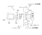
図2は、本実施形態のインクタンクの、インク残量検出モジュール近傍での断面図である。図3は、図2に示すインク残量検出モジュールの斜視図である。なお、図2はインク残量検出モジュール20に関連する主要な構成が表れるように模式的に示した断面であり、特定の領域で切断した断面を示すものではない。
FIG. 2 is a cross-sectional view of the ink tank according to the present embodiment in the vicinity of the ink remaining amount detection module. FIG. 3 is a perspective view of the ink remaining amount detection module shown in FIG. FIG. 2 is a cross-sectional view schematically showing a main configuration related to the remaining ink
図2〜図3を参照して、インク残量検出モジュール20に関連する構造について説明する。カップ部2の底壁のインクタンク1(図1参照)の外表面を構成する面には貫通穴が形成され、この貫通穴にインク残量検出モジュール20が嵌め込まれている。インク残量検出モジュール20は、支持基板21と、支持基板21の第1の面21bに搭載された情報記憶素子22とを有する。情報記憶素子22は、電気的、磁気的あるいは電磁気的に情報の書き込み消去および読み出しが可能な不揮発性の記憶デバイスであり、例えば、EEPROM、フラッシュメモリ、磁気メモリなどを用いることができる。
A structure related to the ink remaining
また、支持基板21の第1の面21bには、情報記憶素子22を覆い、情報記憶素子22がインクや気体と直接接触しないように封止する封止構造体23が設けられている。封止構造体23は、後述する光学センサ52(図5参照)が発する光を透過する部材によって、第1の面21b上で互いに平行でない2つの反射平面を有する三角プリズム形状に形成されている。封止構造体23は、2つの反射平面として、頂上の稜線から支持基板21の第1の面21bの法線に対して45度の角度で傾斜する2つの斜面23a,23b、言い換えれば、支持基板21の第1の面21bに対して45度の角度で傾斜し、頂部で90度の角度を成して交わる2つの斜面23a,23bを有する。
The
支持基板21の第1の面21bと反対側の面である第2の面21cには、情報記憶素子22の端子とそれぞれ配線を介して電気的に接続された複数の外部コンタクト電極24が設けられている。
A plurality of
支持基板21にはさらに、第1の面21bから第2の面21cへ貫通する2つの貫通穴21aが形成されている。各貫通穴21aは、情報記憶素子22を間においてその両側に位置し、かつ、各貫通穴21aの軸線がそれぞれ封止構造体23の別々の斜面23a,23bと交わる位置に形成されている。各貫通穴21a内には、封止構造体23の一部が、第2の面21cからドーム状に盛り上がった状態で充填されている。
The
本実施形態のような封止構造体23は、例えば以下のようにして形成することができる。まず、情報記憶素子22が搭載されるとともに、外部コンタクト電極24、および情報記憶素子22と外部コンタクト電極24とを接続する配線が形成され、さらに、2つの貫通穴21aが形成された支持基板21を用意する。次いで、支持基板21の第1の面21b上での封止構造体23の外形形状と同じ内面形状を有するポッティング枠体を、支持基板21の情報記憶素子22および2つの貫通穴21aを覆って、支持基板21の第1の面21b上に設置する。ポッティング枠体は、紫外線を透過する材料で形成する。次いで、枠体の中に、紫外線硬化型のポッティング樹脂を注入し、この状態で、枠体を介してポッティング樹脂に紫外線を照射し、ポッティング樹脂を硬化させる。最後に、枠体を取り除く。以上により、第1の面21b上では三角プリズム形状を有し、かつ、第2の面21cからドーム状に盛り上がって各貫通穴21a内に充填された封止構造体23を得ることができる。
The sealing
封止構造体23は、支持基板21の第1の面21b上に所定の形状が形成されていれば、必ずしも貫通穴21aに充填されていなくともよい。貫通穴21aに充填されていない封止構造体23は、例えば、封止構造体23を支持基板21の第1の面21b上に形成した後に、貫通穴21aを形成することによって得ることができる。ここで、封止構造体23の、支持基板21の第1の面21b上での「所定の形状」とは、第1の面21bに対して傾斜する複数の斜面を有し、2つの貫通穴21aのうち一方から入射した光がこれら各斜面で反射して他方の貫通穴21aを通って出射することのできる形状である。
The sealing
以上のように構成されたインク残量検出モジュール20は、支持基板21の第1の面21bをインク収容室6側へ向けて、すなわち封止構造体23をインク収容室6内に臨ませて、カップ部2の貫通穴に固定されている。インク残量検出モジュール20をこのように設置することで、支持基板21の第2の面21cはインクタンク1の外表面に露出し、支持基板21の貫通穴21aを通じてインクタンク1の内部と外部との間で光の入出射が可能となる。また、支持基板21の第2の面21cがインクタンク1の外表面に露出する結果、外部コンタクト電極24もインクタンク1の外表面に露出している。インク残量検出モジュール20とカップ部2との隙間には、インク収容室6からのインクの漏れを防止するために、接着剤25が充填されている。
The ink remaining
インク残量検出モジュール20の電気的構成を図4に示す。インクタンク1側では、インク残量検出モジュール20の、情報記憶素子22に接続された各外部コンタクト電極24は、例えば、データ入出力用の端子DI/DO、情報記憶素子22の駆動用の電源端子Vdd、グランド用のコモン端子COM、およびクロック端子CLKとされる。一方、インクジェット記録装置50は、このインクタンク1を着脱可能に保持するキャリッジ51を有し、インクタンク1はキャリッジ51に装着される。このキャリッジ51は、インクを吐出するインクジェット記録ヘッド(不図示)を一体にまたは着脱可能に搭載しており、インクタンク1からインクジェット記録ヘッドにインクを供給し、供給されたインクをインクジェット記録ヘッドから吐出することで、紙や樹脂シートなどの記録媒体に記録を行う。
FIG. 4 shows an electrical configuration of the ink remaining
このキャリッジ51には、インクタンク1が装着されたときに、各外部コンタクト電極24とそれぞれ電気的に接続される、コンタクト端子51aが設けられている。また、インクジェット記録装置50には、光学センサ52が備えられている。光学センサ52は、インクタンク1が装着されるキャリッジ51に設けられていてもよいし、他の部材に設けられていてもよい。光学センサ52は、インク残量検出モジュール20に向けて光を照射し、その戻り光を検出することで、戻り光の強度に応じたアナログ信号を得る。このアナログ信号は、インクジェット記録装置50の制御部へ送られ、インクタンク1内のインク残量に関する情報を表すデジタル信号に変換される。この信号は、コンタクト端子51aを介してインク残量検出モジュール20の情報記憶素子22に送られ、インク残量に関する情報として情報記憶素子22に格納される。また、情報記憶素子22に格納されたインク情報に関する情報は、コンタクト端子51aを介してインクジェット記録装置50の制御部へ送られる。
The carriage 51 is provided with
コンタクト端子51aは、インクタンク1がキャリッジ51に装着されることによって、外部コンタクト電極24と接触し、これによって電気的な接続がなされる。インクタンク1がキャリッジ51に装着されたときに、コンタクト端子51aを外部コンタクト電極24に良好に接触させるために、例えば図5に示すように、コンタクト端子51aは、導電性を有する部材からなる板ばねとして構成するのが好ましい。なお、図5に示すコンタクト端子51aは、インクタンク1との接続部の構造の一例を示すものであり、形状や配置等は適宜変更することができる。
The
また、図5を参照すると、光学センサ52は、光を照射する発光部52aと、光を受光する受光部52bとを有する。光学センサ52は、キャリッジに搭載されている場合はインク残量検出モジュール20と対向する位置、また、キャリッジ以外の部材に搭載されている場合はキャリッジが所定の位置にあるときにインク残量検出モジュール20と対向する位置など、少なくともインク残量の検出時にインク残量検出モジュール20に対向する位置に配置される。特に、この位置では、発光部52aが2つの貫通穴21aのうち一方と対向し、受光部52bが2つの貫通穴21aのうち他方と対向している。また、光学センサ52は、発光部52aから出射する光の光束の中心光軸が支持基板21の第1の面21bに対して垂直となるように配置されている。
Referring to FIG. 5, the
発光部52aから発する光の波長は特に限定されないが、封止構造体23によって減衰されにくい波長の光とすることが望ましい。例えば、封止構造体23としてエポキシ系のポッティング樹脂を用いた場合は、発光部52aから照射する光として赤外線を用いるのが好ましい。また、発光部52aからの光を効率よく利用できるようにするために、発光部52aからは集光光を出射することが好ましい。さらに、本実施形態のように、貫通穴21aの内部も封止構造体23を構成する材料で充填した場合、支持基板21の第2の面21cからドーム状に盛り上がった形状とすることで、より集光効果が向上するので好ましい。
The wavelength of the light emitted from the
引き続き図5を参照して、本実施形態によるインク残量の検出について説明する。光学センサ52の発光部52aから出射した光は、支持基板21の一方の貫通穴21aを通って、封止構造体23に入射し、封止構造体23内を進行して一方の斜面23aに達する。
With reference to FIG. 5, the detection of the remaining amount of ink according to the present embodiment will be described. The light emitted from the
ここで、インク収容室6内に十分にインクがある場合、すなわち、発光部52aから出射した光の、斜面23aへの到達点よりも高い位置にインク液面が位置している場合は、図5(a)に示すように、封止構造体23を透過する。そのため、発光部52aからの光は受光部52bへは戻らず、受光部52bでは検出されない。したがって、光学センサ52からは何の出力も得られず、インクジェット記録装置50の制御部(図4参照)は、これをインク有りと判断する。制御部は、その判断結果に基づき、所定のコンタクト端子51a(図4に示した端子DI/DO)を通じて、インク有りを表す情報を、インク残量検出モジュール20の情報記憶素子22に書き込む。
Here, when there is sufficient ink in the
インク収容室6内のインクが消費され、図5(b)に示すように、インク収容室6内のインク液面の位置が、発光部52aから出射した光の斜面23aへの到達点よりも低い位置の状態となった場合は、発光部52aから出射した光は、封止構造体23内を進行する過程で、その2つの斜面23a,23bで反射され、もう一方の貫通穴21aを通って受光部52bに入射する。このことにより、光学センサ52からは受光部52bに入射した光の強度に応じたアナログ信号が得られる。このアナログ信号は、インクジェット記録装置50の制御部へ送られ、制御部はこれをインク無しと判断する。そして制御部は、その判断結果に基づき、所定のコンタクト端子51a(図4に示した端子DI/DO)を通じて、情報記憶素子22に格納されている情報を、インク無しを表す情報に更新する。このデータの更新は、情報記憶素子22に書き込まれているインク有りを示すデータを書き換えることによって行ってもよいし、インク有りを示すデータを残したまま、情報記憶素子22内の別の記憶領域にインク無しを示すデータを書き加えることによって行ってもよい。それと同時に、制御部は、インクジェット記録装置50自身を通じて、ユーザに対してインクがない旨の警告を発してインクタンク1の交換を促すとともに、必要に応じて記録動作を中断する。
The ink in the
上述した、光学プリズム中を通過する光の反射/透過を利用した光学的なインク残量検出の原理は、公知であるので、ここではその詳細な説明は省略する。 Since the principle of the optical ink remaining amount detection using reflection / transmission of light passing through the optical prism described above is well known, detailed description thereof is omitted here.
以上説明したように、本実施形態によれば、インク残量検出モジュール20は、情報記憶素子22を有しているので、光学センサ52によって検出された、インク残量に関する情報を、この情報記憶素子22に書き込むことができる。その結果、インク残量に関する情報の書き込みに用いられる外部コンタクト電極24を利用して、情報記憶素子22に記憶されているデータを読み出すことによって、インクタンク1内のインク残量に関する情報を簡便かつ確実に知ることができる。しかも、情報記憶素子22は支持基板21のインク収容室6側を向いた面に搭載され、結果的に情報記憶素子22は支持基板21に保護されることになるので、情報記憶素子22の損傷が防止される。また、外部コンタクト電極24は、支持基板21の情報記憶素子22が搭載された面とは反対側の面に設けられ、インクタンク1の外表面に露出しているので、情報記憶素子22への情報の書き込みは容易である。
As described above, according to the present embodiment, since the ink remaining
情報記憶素子22はインク収容室6側を向いて設置されるので、情報記憶素子22がインクに直接接触しないように、情報記憶素子22を封止する必要がある。そこで、情報記憶素子22を封止する封止構造体23を、光を透過する部材で構成することにより、この封止構造体23を、インク残量を光学的に検出するのに用いる光学プリズムと兼用することができる。その結果、情報記憶素子22を搭載する支持基板21とは別に、インク残量検出のための光学プリズムを設ける必要がなくなるので、インク残量検出モジュール20の小型化が達成される。したがって、インク残量検出モジュール20は小型のインクタンク1にも、そのコンパクト性を損なうことなく搭載することができ、ひいては小型のインクジェット記録装置50にも適したものとなる。
Since the
インク残量に関する情報は厳密である必要はなく、「有り/無し」程度の段階的な情報で良く、データ量も比較的少なくてよい。情報記憶素子22としても半導体を利用した小型のチップ状素子を用いることができるので、情報記憶素子22を搭載したとしても、インク残量検出モジュール20の小型化が損なわれることはない。情報記憶素子22は、ワンチップ構成に限らず、ハイブリッド構成であってもよい。また、情報記憶素子22としては、情報の消去および書き込みによって情報を書き換えるものに限定されるものではなく、記録済みの領域とは別の領域に逐次追記が可能なもの、すなわち、少なくとも書き込みおよび読み出しが行えるものであってもよいことはもちろんである。
The information regarding the remaining amount of ink does not need to be strict, and may be step-by-step information of “Yes / No”, and the amount of data may be relatively small. Since a small chip-like element using a semiconductor can be used as the
以上の説明では、インク残量検出モジュール20が取り扱う情報が、インク「有り/無し」である場合について説明したが、発光部52aから出射する光は、厳密にはある程度の広がりを持っており、「インク有り」と判断される状態と「インク無し」と判断される状態との境界部では、受光部52bに入射する光の強度はアナログ的に変化する。そこで、検出精度の高い受光部52bを備えた光学センサ52を用いれば、インク「有り/無し」だけでなく、インク収容室6内のインク残量が僅かであることも検出できる。
In the above description, the case where the information handled by the ink remaining
情報記憶素子22には、インク残量に関する情報だけでなく、他の情報を格納することもできる。情報記憶素子22に格納できる他の情報としては、そのインクタンク1に固有の情報、例えば、品番、収容されているインクの種類、色、製造年月日、ロット番号などが挙げられる。これらの情報は、インクタンク1の製造時に、情報記憶素子22に予め書き込んでおく。
The
インクジェット記録装置50の制御部は、インクタンク1が装着されたときに、情報記憶素子22に書き込まれている情報を読み込む。インクジェット記録装置50側には、情報記憶素子22に書き込まれている情報との比較の対照となるデータが格納されている。インクジェット記録装置50は、このデータをインクタンク1側のデータと比較することによって、装着されたインクタンク1がこのインクジェット記録装置50に適合するものであるか否か、装着位置が正しいか否か、などを判断し、必要に応じてユーザに警告を発することができる。
The control unit of the ink jet recording apparatus 50 reads information written in the
インクタンク1は、インクを消費しきった後に、インクを再充填して再使用されることもある。インクジェット記録装置50に装着されたインクタンク1が、インクを再充填した再使用品である場合、そのインク残量検出モジュール20の情報記憶素子22には、インク残量に関する情報として「インク無し」を意味する情報が書き込まれている。したがって、インクジェット記録装置50に再使用品であるインクタンク1が装着されたとき、インク残量に関する情報について、光学センサ52から得られる情報と、情報記憶素子22から得られる情報との間に矛盾が生じる。
The ink tank 1 may be reused by being refilled with ink after the ink has been consumed. When the ink tank 1 attached to the ink jet recording apparatus 50 is a reused product refilled with ink, the
そこで、このような場合、インクジェット記録装置50の制御部は、光学センサ52から得られた情報を優先的に用い、情報記憶素子22のインク残量に関する情報を書き換えれば、上記の矛盾は解消される。あるいは、インクタンク1の再利用品の製造時も新規の製造時も含め、インクタンク1の製造工程において、インクが充填されていない筐体4(図1参照)を用意しておき、この筐体4内にインクを充填した後、情報記憶素子22に、インク残量に関する情報として「インク有り」を意味する情報を書き込む。ここでいう情報の書き込みは、新たに書き込むことだけでなく、既に書き込まれている情報を更新することも含む。例えば、再利用品のインクタンク1においては、情報記憶素子22には、「インク無し」を意味する情報が既に書き込まれているので、このような場合は、「インク無し」の意味する情報を「インク有り」を意味する情報に書き換えてもよいし、情報記憶素子22の別の領域に「インク有り」を意味する情報を追記してもよい。インクの充填は、インクタンク1の使用時の姿勢において、少なくとも封止構造体にインクが接触し、かつ接触したインクがインク供給口まで連通するように、インクを充填する。
Therefore, in such a case, if the control unit of the inkjet recording apparatus 50 preferentially uses the information obtained from the
こうすることによって、再使用品のインクタンク1をインクジェット記録装置50に装着したときであっても、光学センサ52から得られる情報と、情報記憶素子22から得られる情報との間に矛盾は生じない。また、インクタンク1が新品か使用済みか、外見だけからは不明な場合においても、情報記憶素子22に格納されている情報を読み出すことによって、インクタンク1内のインクの有無を簡便かつ確実に確認することができる。
By doing so, even when the reused ink tank 1 is mounted on the ink jet recording apparatus 50, there is a contradiction between the information obtained from the
ところで、インクジェット記録装置50として現在最も普及しているのは、複数色のインクを用いてフルカラーの画像を出力することのできるものである。そのために、インクジェット記録装置50は、それぞれ異なる色のインクを収容した複数のインクタンク1を装着する構成とし、各色のインクタンク1は、その筐体部材を共通で用い、収容するインクの色だけを変更した構成とする場合が多い。各色のインクタンク1は、予め決められた所定の位置に装着される。このような場合、情報記憶素子22には、インク残量に関する情報だけでなく、インクの色に関する情報も書き込むことが望ましい。そして、インクジェット記録装置50の制御部は、情報記憶素子22に書き込まれているインクの色に関する情報も読み出し、そのインクタンク1が所定の位置に装着されているか否かを判断するように構成することで、ユーザのインクタンク1の誤装着も検出することができる。
By the way, what is most widely used as the ink jet recording apparatus 50 can output a full-color image using a plurality of colors of ink. Therefore, the ink jet recording apparatus 50 is configured to mount a plurality of ink tanks 1 each containing different colors of ink, and each color ink tank 1 uses a casing member in common and only the color of the ink to be stored. In many cases, the configuration is changed. Each color ink tank 1 is mounted at a predetermined position. In such a case, it is desirable to write not only information regarding the remaining ink amount but also information regarding the color of the ink in the
このようなカラー記録用のインクタンク1を再利用する場合、使用済みのインクタンク1においては、インクの色に関する情報が情報記憶素子22に既に書き込まれている。したがって、インクタンク1にインクを充填する際には、インクを充填する前に、情報記憶素子22に書き込まれているインクの色に関する情報を読み出し、その情報に対応する色と同じ色のインクを充填すれば、情報記憶素子22に書き込まれているインクの色に関する情報を書き換える必要がない。インクの色に関する情報に対応する色とは異なる色のインクを充填することもできるが、この場合は、充填するあるいは充填したインクの色に応じて、情報記憶素子22に書き込まれているインクの色に関する情報を書き換える。また、インクタンク1を再利用する場合、インクを充填する前に、インク室内を洗浄することが望ましい。これは、インクタンク1がカラー記録用のインクタンク1であって、前回収容していた色と異なる色のインクを収容する場合は、インク室内に僅かにインクが残っている場合があるのでインクの混色を防止するうえで特に好ましい。ただし、同じ色のインクを収容する場合や、単色記録が前提であり情報記憶素子22にインクの色に関する情報が含まれていない場合においても、インク室内に僅かに残っているインクが経時的に変質している場合があるので、インク室を洗浄することは有効である。
When the ink tank 1 for color recording is reused, information on the ink color is already written in the
上述した例では、インクタンク1とインクジェット記録装置50との間での情報の伝達に、電極同士の物理的な接触を伴う例を示したが、非接触型とすることもできる。図6に、その一例を示す。 In the example described above, an example is shown in which information is transmitted between the ink tank 1 and the ink jet recording apparatus 50 with physical contact between the electrodes. However, a non-contact type may be used. An example is shown in FIG.
図6に示すインク残量検出モジュール30は、RF−ID(Radio Frequency Identification)と呼ばれる方式により、マイクロ波と呼ばれる数GHzオーダーの高周波電波を利用して非接触で情報の送受信を行うものであり、光を透過する部材で形成された三角プリズム形状を有する封止構造体(不図示)で封止された情報記憶素子32と、情報記憶素子32とインクジェット記録装置との間で情報の送受信を行うためのアンテナ部34とを有する。これら情報記憶素子32およびアンテナ部34は、支持基板(不図示)上に設けられている。情報記憶素子32は、インクタンクの外部に露出しないように支持基板の片側の面に設けられ、アンテナ部34は、受信すべき電波の高周波エネルギーがインクタンク内のインクに吸収されることをできるだけ避けるため、情報記憶素子32とは反対側の面に設けられる。一方、インクジェット記録装置には、インク残量検出モジュール30との間での情報の送受信のためのアンテナ部36と、インクタンク内のインク残量を光学的に検出するための光学センサ37とが設けられている。
The ink remaining
情報記憶素子32は、図6(b)に示すように、インク残量に関する情報、またはインク残量に関する情報およびインクタンク固有の情報を格納するメモリ領域32cと、アンテナ部34に接続された、RF信号をデジタル信号へ変換したりデジタル信号をRF信号へ変換したりするRF部(高周波処理部)32dと、アンテナ部34を介してインクジェット記録装置から送信されRF部で変換されたデジタル信号をインク残量に関するデータ形式に変換したり、変換したインク残量に関するデータをメモリ領域32cに書き込んだり、変換したインク残量に関するデータをRF部32dに送ったり、メモリ領域32cおよびRF部32d間での相互の信号のやり取りを制御するロジック部32bとを有する。
As shown in FIG. 6B, the
このように、非接触で情報の送受信を行う構成とすることで、インク残量検出モジュール30およびインクジェット記録装置には相互間での情報の伝達のための接触構造が不要となるので、より簡便かつコンパクトに構成することができるとともに、インク残量検出モジュール30の取り付け位置の自由度も大幅に向上する。
In this way, by adopting a configuration in which information is transmitted and received in a non-contact manner, the ink remaining
以上、情報記憶素子としてGHzオーダーの高周波電波を利用したRF−IDを用いた例を説明したが、本発明においては、コンパクトさの点では高周波電波を利用したRF−IDにやや劣るものの、高周波電磁誘導を利用した電磁誘導結合型のRF−IDを用いても、インク残量検出手段と一体化された情報記憶手段が持つ大きな作用効果が得られることは言うまでもない。電磁誘導を利用した場合、アンテナ部としてはループコイルアンテナが用いられる。 As described above, the example using the RF-ID using the high-frequency radio wave of the GHz order as the information storage element has been described. However, in the present invention, the RF-ID using the high-frequency radio wave is slightly inferior in terms of compactness. It goes without saying that even if an electromagnetic induction coupling type RF-ID using electromagnetic induction is used, the great effect of the information storage means integrated with the ink remaining amount detection means can be obtained. When electromagnetic induction is used, a loop coil antenna is used as the antenna unit.
次に、本発明によるインク残量検出モジュールの構造の他の例を、図7(a)〜(c)を参照して説明する。 Next, another example of the structure of the ink remaining amount detection module according to the present invention will be described with reference to FIGS.
図7(a)に示すインク残量検出モジュール40は、支持基板41が、光学センサ(不図示)から出射される光を透過する材料で構成されている。光を透過する支持基板41に適した材料としては、透明樹脂やガラス材などが挙げられる。このように、光を透過する支持基板41を用いることで、封止構造体43に光を入射させるための貫通穴を支持基板41に形成する必要がなくなる。
In the remaining ink
支持基板41への、外部コンタクト電極44や情報記憶素子42と外部コンタクト電極44とを接続する配線の形成には、スクリーン印刷、エッチング、あるいは銅箔貼りなどの方法を利用することができる。支持基板41を構成する材料は、光学センサからの光を透過することができるものであれば特に限定されず、支持基板41の生産性、外部コンタクト電極44や配線の形成のし易さ、インクタンクとの接着性などを考慮して適宜選択することができる。
For forming the
光を透過する材料で支持基板41を構成した場合、外部からの意図しない光が封止構造体43に入射し易くなる。意図しない光が封止構造体43に入射すると、これが迷光となってインク残量の誤検出につながることもある。そこで、支持基板41の片面あるいは両面の一部に遮光マスク(不図示)を形成し、封止構造体43に不必要な光が入射しないようにすることが望ましい。遮光マスクは、例えば、外部コンタクト電極44や配線の形成時に、これらのパターンとともに、ダミーパターンとして形成することができる。
When the
図7(b)に示す例は、上述した遮光マスクを利用して、インクの有り/無しだけでなくインクタンクの有り/無しも検出できるように構成した例である。図7(b)において、インク残量検出モジュール45は、その支持基板46の片面の一部に形成された反射体として遮光マスク48を有している。遮光マスク48は、インクジェット記録装置に設けられた光学センサ52の発光部52aから出射した光を反射する材料で形成されている。
The example shown in FIG. 7B is an example in which not only the presence / absence of ink but also the presence / absence of an ink tank can be detected using the above-described light shielding mask. In FIG. 7B, the ink remaining
光学センサ52は、インクタンクに対して、実線で示す第1の位置と破線で示す第2の位置との間を相対的に移動可能に設けられている。第1の位置は、インクタンクが装着されているときに、発光部52aから出射した光が遮光マスク48で反射して受光部52bに戻ることのできる位置である。仮に、この第1の位置で、発光部52aから出射した光が受光部52bで検出できなかった場合は、遮光マスク48での反射がなかったということであるので、これによって、インクタンクが装着されていないことを検出できる。
The
第2の位置は、インク残量を検出するための位置であり、この位置では前述したように、発光部52aから出射して封止構造体47に入射した光が受光部52bに戻るか否かに応じてインクの有り/無しを検出することができる。
The second position is a position for detecting the remaining amount of ink. At this position, as described above, whether or not the light emitted from the
従来の簡便な光学的検出方式では、インクタンクが装着されていない場合もインク有りと同じ検出結果を示すので、インクタンクの有無を検出したい場合は、インクタンクの有無検出用のセンサを、インク残量検出用のセンサとは別に設ける必要があった。それに対して本例では、2種類のセンサを設けることなく、「インクタンク無し」と「インク有り」とを区別して検出することができる。 The conventional simple optical detection method shows the same detection result as the presence of ink even when the ink tank is not installed. Therefore, if it is desired to detect the presence or absence of the ink tank, a sensor for detecting the presence or absence of the ink tank is used. It was necessary to provide it separately from the sensor for detecting the remaining amount. On the other hand, in this example, “without ink tank” and “with ink” can be distinguished and detected without providing two types of sensors.
なお、図7(b)から明らかなように、インクタンクの有無を検出するときに利用する光の発光部52aからの出射方向は、インク残量を検出するときに利用する光の発光部52aからの出射方向とは異なっている。しかし、発光部52aから出射した光には集光しきれていない方向成分の光もあり、その集光しきれていない光を利用すれば、発光部52aからの光を遮光マスク48で反射させて受光部52bで受光することも可能である。
As is clear from FIG. 7B, the light emission direction from the
図7(b)では遮光マスク48を、支持基板46の封止構造体47が設けられた面(第1の面)に形成した例を示したが、その反対側の、光学センサ52が配置された側の面(第2の面)に形成してもよい。また、図7(b)に示した例では、支持基板46が光を透過する部材からなる例を示したが、光を透過しない部材からなり、その代わりに、光が通過する2つの貫通穴を有する支持基板であっても、反射体を支持基板の第2の面に形成すれば、同様の効果が得られる。
Although FIG. 7B shows an example in which the
図7(c)に示す例は、図6に示した、インクジェット記録装置との間での情報のやり取りを非接触で行うインク残量検出モジュール30の構造の一例である。支持基板31の、情報記憶素子32が搭載された面と反対側の面に設けられているのは、アンテナ部34である。インクジェット記録装置との間での情報のやり取りは、このアンテナ部34を介して非接触で行われるので、外部コンタクト電極は不要である。この例でも、支持基板31は、光学センサ(不図示)からの光を透過する部材で形成されており、支持基板31には、光学センサからの光を封止構造体33へ入射させるための貫通穴は不要である。
The example shown in FIG. 7C is an example of the structure of the ink remaining
もちろん、図7(c)に示す例においても、迷光による誤検出を防止するための遮光マスクや、インクタンクの有り/無しを検出するための反射体を、支持基板31の一部に形成してもよい。
Of course, also in the example shown in FIG. 7C, a light shielding mask for preventing erroneous detection due to stray light and a reflector for detecting the presence / absence of an ink tank are formed on a part of the
上述した各例では、封止構造体が全体としてプリズム形状を有している例を説明したが、封止構造体は、少なくともインク残量検出用の光の光路となる部分が、光を透過する部材からなるプリズム形状であれば、その形状は任意である。その一例を図8に示す。図8に示すインク残量検出モジュール55は、支持基板56と、その片面に搭載された情報記憶素子57と、支持基板56の片面に設けられて情報記憶素子57を封止する封止構造体58と、インク残量に関する情報を情報記憶素子57と外部との間でやり取りするための情報伝達手段(不図示)とを有する。情報伝達手段としては、上述したような外部コンタクト電極やアンテナ部を用いることができる。
In each of the above-described examples, the example in which the sealing structure has a prism shape as a whole has been described. However, the sealing structure transmits light at least at a portion that is an optical path of light for detecting the remaining amount of ink. If it is a prism shape which consists of a member to do, the shape is arbitrary. An example is shown in FIG. 8 includes a
封止構造体58は、光を透過する部材からなり、三角プリズム部58aと、その裾野の片側を延長した封止部58bとを有する形状とされている。情報記憶素子57は、封止部58bに封止されている。支持基板56は、光を透過する部材からなるものでもよいし、光を透過しない部材からなるものでもよい。支持基板56が光を透過しない部材からなる場合は、支持基板56の、三角プリズム部58aが設けられている領域に、インク残量検出用の光を透過させるための2つの貫通穴(不図示)が設けられる。支持基板56が光を透過する部材からなる場合は、インク残量検出用の光は、三角プリズム部58aに向けて照射される。このように、封止構造体58を、インク残量検出用の部分と情報記憶素子57を封止する部分とに分けた構造としても上述した例と同様の効果が得られる。
The sealing
なお、図8に示した例においては、封止構造体58の封止部58bは、光を透過する部材で構成する必要はないので、この部分は光を透過しない部材で構成してもよい。また、三角プリズム部58aと封止部58bとは一体でもよいし別体でもよい。なお、本例においても、支持基板56の一部に、上述したような遮光マスクや反射体を設けてもよい。
In the example shown in FIG. 8, the sealing
次に、本発明が適用可能なインクタンクの形態について説明する。上述した実施形態では、図1に示したように、負圧発生部材収納室5とインク収容室6とを有するインクタンク1に本発明を適用した例を示したが、本発明はこれに限定されるものではない。
Next, the form of the ink tank to which the present invention can be applied will be described. In the above-described embodiment, as shown in FIG. 1, the example in which the present invention is applied to the ink tank 1 having the negative pressure generating
図9に、本発明を適用したインクタンクの他の例の断面図を示す。図9に示すインクタンク60は、筐体の内部が全て、インクを直接収容するインク収容室65となっている。インクタンク60の底壁には、収容されているインクを記録ヘッド(不図示)に供給するためのインク供給口62が形成されている。インク供給口62には弾性弁膜63が設けられている。弾性弁膜63は、インクタンク60をインクジェット記録装置(不図示)に装着したとき、インク導出管(不図示)が挿入されたときにのみ開き、これによって、インクタンク60がインクジェット記録装置に装着されていない状態でのインクタンク60からのインクの漏れを防止している。
FIG. 9 shows a cross-sectional view of another example of an ink tank to which the present invention is applied. In the ink tank 60 shown in FIG. 9, the interior of the casing is an
また、インクタンク60の底壁には、インク収容室65内に負圧を発生させるための負圧発生構造64が設けられている。負圧発生構造64は、インクタンク60の外側表面に対して凹状に形成された第1の凹部64aと、インクタンク60の内側表面に対して凹状に形成された第2の凹部64bと、これら凹部64a,64b間を連絡する、例えば蛇行した経路とされた連絡通路64cとを有する。インクタンク60の内圧は外圧より低く、インクは第2の凹部64bにおいてメニスカスを形成してインク収容室65内に保持されている。インクの消費に伴って内圧が小さくなると、それに伴って連絡通路64cを通じてインク収容室65内に空気が導入され、これによりインク収容室65が所定の負圧に保たれる。
A negative pressure generating structure 64 for generating a negative pressure in the
インクタンク60の側壁には、インク残量検出モジュール61が取り付けられている。インク残量検出モジュール61としては上述した各形態のいずれも用いることができ、光を透過する部材で形成された、情報記憶素子(不図示)を封止するとともに光学プリズムとして機能する封止構造体がインク収容室65内のインクと接触するように取り付けられる。このように、インク残量検出モジュール61をインクタンク60の側壁に取り付けることで、インクタンク60の使用時の姿勢における高さ方向でのインク残量検出モジュール61の取り付け位置を適宜設定することで、インク無しを検出したいインク液面レベルを任意に設定することができる。
An ink remaining
なお、本発明の作用効果を確実に得るためには、残量検知したいインク量に対応した位置に封止構造体を配置するのはもちろんのこと、少なくとも封止構造体に接触するようにインクが充填され、かつ充填されたインクがインク供給部近傍にまで連通するようにインクが収容されていることが重要である。このことは、使用済みのインクタンクに再充填して再利用する場合にも同様である。 In order to reliably obtain the effects of the present invention, the sealing structure is arranged at a position corresponding to the amount of ink whose remaining amount is to be detected, and at least the ink is arranged so as to contact the sealing structure. It is important that the ink is contained so that the filled ink is communicated to the vicinity of the ink supply unit. The same applies to the case where the used ink tank is refilled and reused.
1 インクタンク
4 筐体
5 負圧発生部材収納室
6 インク収容室
10 インク供給口
20,30,40,45 インク残量検出モジュール
21,31,41,46 支持基板
21a 貫通穴
22,32,42 情報記憶素子
23,43,47 封止構造体
24,44 外部コンタクト電極
50 インクジェット記録装置
51 キャリッジ
51a コンタクト端子
52 光学センサ
DESCRIPTION OF SYMBOLS 1
Claims (19)
第1の面およびその反対側の第2の面を有し、前記第1の面から前記第2の面へ貫通する2つの貫通穴が形成された支持基板と、
前記支持基板の第1の面に設けられた、情報の書き込みおよび読み出しが可能な不揮発性の情報記憶手段と、
前記支持基板の第1の面に、前記情報記憶手段および前記2つの貫通穴を覆い、かつ少なくとも前記2つの貫通穴を覆う部位が光を透過する部材でプリズム形状に形成された、前記情報記憶手段を封止する封止構造体と、
前記支持基板に設けられた、インク残量に関する情報を前記情報記憶手段に書き込むために外部から伝達し、かつ前記情報記憶手段に書き込まれた情報を外部へ伝達するための情報伝達手段とを有するインク残量検出モジュール。 An ink remaining amount detection module attached to the ink tank for detecting the remaining amount of ink in the ink tank used for ink jet recording,
A support substrate having a first surface and a second surface opposite to the first surface, wherein two through holes penetrating from the first surface to the second surface are formed;
Non-volatile information storage means provided on the first surface of the support substrate and capable of writing and reading information;
The information storage, wherein the information storage means and the two through holes are formed on a first surface of the support substrate, and at least a portion covering the two through holes is formed in a prism shape with a light transmitting member. A sealing structure for sealing the means;
An information transmission unit provided on the support substrate for transmitting information on the remaining amount of ink to the information storage unit from outside and transmitting the information written to the information storage unit to the outside; Ink level detection module.
第1の面およびその反対側の第2の面を有し、光を透過する部材からなる支持基板と、
前記支持基板の第1の面に設けられた、情報の書き込みおよび読み出しが可能な不揮発性の情報記憶手段と、
前記支持基板の第1の面に、前記情報記憶手段を覆い、かつ少なくとも一部が光を透過する部材でプリズム形状に形成された、前記情報記憶手段を封止する封止構造体と、
前記支持基板に設けられた、インク残量に関する情報を前記情報記憶手段に書き込むために外部から伝達し、かつ前記情報記憶手段に書き込まれた情報を外部へ伝達するための情報伝達手段とを有するインク残量検出モジュール。 An ink remaining amount detection module attached to the ink tank for detecting the remaining amount of ink in the ink tank used for ink jet recording,
A support substrate having a first surface and a second surface opposite to the first surface and made of a light transmitting member;
Non-volatile information storage means provided on the first surface of the support substrate and capable of writing and reading information;
A sealing structure for sealing the information storage means, which is formed on the first surface of the support substrate so as to cover the information storage means, and at least part of which is formed in a prism shape with a member that transmits light;
An information transmission unit provided on the support substrate for transmitting information on the remaining amount of ink to the information storage unit from outside and transmitting the information written to the information storage unit to the outside; Ink level detection module.
請求項1ないし5のいずれか1項に記載のインク残量検出モジュールと、
前記インク室の外壁および前記インク供給口を構成する筐体部材とを有し、
前記インク残量検出モジュールは、前記封止構造体を前記インク室に露出させ、かつ前記支持基板の第2の面を外表面に露出させて、前記筐体部材に取り付けられていることを特徴とするインクタンク。 In an ink tank having an ink chamber for containing ink therein, and an ink supply port for supplying ink in the ink chamber to a recording head,
An ink remaining amount detecting module according to any one of claims 1 to 5,
A housing member constituting the outer wall of the ink chamber and the ink supply port;
The ink remaining amount detection module is attached to the housing member with the sealing structure exposed to the ink chamber and the second surface of the support substrate exposed to the outer surface. Ink tank.
前記インクタンクを着脱可能に保持する保持部と、
前記保持部に保持された前記インクタンクの前記インク残量検出モジュールに向けて光を出射する光学センサと、
前記インクタンクに取り付けられた前記インク残量検出モジュールの前記情報伝達手段を介して前記インク残量検出モジュールとの間で情報のやり取りを行うための装置側情報伝達手段を有するインクジェット記録装置。 An ink jet recording apparatus, wherein the ink tank according to any one of claims 6 to 8 is detachably mounted, and recording is performed on a recording medium using a recording head that discharges ink supplied from the ink tank. ,
A holding unit for detachably holding the ink tank;
An optical sensor that emits light toward the ink remaining amount detection module of the ink tank held by the holding unit;
An ink jet recording apparatus comprising apparatus-side information transmitting means for exchanging information with the ink remaining amount detecting module via the information transmitting means of the ink remaining amount detecting module attached to the ink tank.
前記インクタンクを着脱可能に搭載する保持部と、
前記保持部に保持された前記インクタンクの前記インク残量検出モジュールに向けて光を出射する光学センサと、
前記インクタンクに取り付けられた前記インク残量検出モジュールの前記情報伝達手段を介して前記インク残量検出モジュールとの間で情報のやり取りを行うための装置側情報伝達手段とを有し、
前記インクタンクは、インクを内部に収容すべきまたは収容したインク室の外壁を構成する筐体部材を備えるとともに、前記インク残量検出モジュールが、前記封止構造体を前記インク室に露出させ、かつ前記支持基板の第2の面を外表面に露出させて、前記筐体部材に取り付けられており、
前記装置側情報情報伝達手段は、前記インクタンクが前記保持部に装着されたときに、前記インク残量検出モジュールの外部コンタクト電極と接触するコンタクト端子を有するインクジェット記録装置。 An ink jet recording apparatus that detachably mounts an ink tank including the ink remaining amount detecting module according to claim 3 and that records on a recording medium using a recording head that discharges ink supplied from the ink tank. And
A holding part for detachably mounting the ink tank;
An optical sensor that emits light toward the ink remaining amount detection module of the ink tank held by the holding unit;
Device-side information transmission means for exchanging information with the ink remaining amount detection module via the information transmission means of the ink remaining amount detection module attached to the ink tank;
The ink tank includes a housing member that constitutes an outer wall of the ink chamber that should contain or contain ink, and the ink remaining amount detection module exposes the sealing structure to the ink chamber, And the second surface of the support substrate is exposed to the outer surface, and is attached to the housing member,
The apparatus-side information information transmission unit includes an ink jet recording apparatus having a contact terminal that contacts an external contact electrode of the ink remaining amount detecting module when the ink tank is mounted on the holding unit.
前記インクタンクを着脱可能に搭載する保持部と、
前記保持部に保持された前記インクタンクの前記インク残量検出モジュールに向けて光を出射する光学センサと、
前記インクタンクに取り付けられた前記インク残量検出モジュールの前記情報伝達手段を介して前記インク残量検出モジュールとの間で情報のやり取りを行うための装置側情報伝達手段とを有し、
前記インクタンクは、インクを内部に収容すべきまたは収容したインク室の外壁を構成する筐体部材を備えるとともに、前記インク残量検出モジュールが、前記封止構造体を前記インク室に露出させ、かつ前記支持基板の第2の面を外表面に露出させて、前記筐体部材に取り付けられており、
前記装置側情報伝達手段は、前記インク残量検出モジュールのアンテナ部との間で情報の送受信を行う装置側アンテナ部を有するインクジェット記録装置。 An ink jet recording apparatus in which an ink tank including the ink remaining amount detecting module according to claim 4 is detachably mounted, and recording is performed on a recording medium using a recording head that discharges ink supplied from the ink tank. And
A holding part for detachably mounting the ink tank;
An optical sensor that emits light toward the ink remaining amount detection module of the ink tank held by the holding unit;
Device-side information transmission means for exchanging information with the ink remaining amount detection module via the information transmission means of the ink remaining amount detection module attached to the ink tank;
The ink tank includes a housing member that constitutes an outer wall of the ink chamber that should contain or contain ink, and the ink remaining amount detection module exposes the sealing structure to the ink chamber, And the second surface of the support substrate is exposed to the outer surface, and is attached to the housing member,
The apparatus-side information transmission unit includes an apparatus-side antenna unit that transmits and receives information to and from the antenna unit of the ink remaining amount detection module.
前記前記光学センサは、前記インクタンクに対して、前記光学センサから出射した光が、前記反射体で反射される第1の位置と前記インク残量検出モジュールの前記封止構造体へ入射する第2の位置との間を相対的に移動する、請求項9ないし11のいずれか1項に記載のインクジェット記録装置。 A reflector that reflects light is formed on a part of the support substrate of the ink remaining amount detection module,
The optical sensor has a first position where light emitted from the optical sensor is reflected by the reflector and enters the sealing structure of the ink remaining amount detection module with respect to the ink tank. The ink jet recording apparatus according to claim 9, wherein the ink jet recording apparatus moves relatively between two positions.
前記インク室の外壁および前記インク供給口を構成し、かつ、請求項1ないし5のいずれか1項に記載のインク残量検出モジュールが前記封止構造体を前記インク室に露出させて取り付けられた筐体部材を用意する工程と、
前記インク室内にインクを充填する工程と、
前記インク残量検出モジュールの前記情報記憶手段に、インク有りを意味する情報を書き込む工程とを有するインクタンクの製造方法。 In a method of manufacturing an ink tank having an ink chamber containing ink therein and an ink supply port for supplying ink in the ink chamber to a recording head,
The ink remaining amount detecting module according to any one of claims 1 to 5 is attached so as to expose the sealing structure to the ink chamber, and constitutes an outer wall of the ink chamber and the ink supply port. Preparing a housing member,
Filling the ink chamber with ink;
A method of manufacturing an ink tank, comprising: writing information indicating the presence of ink in the information storage unit of the ink remaining amount detection module.
前記情報記憶手段にインク有りを意味する情報を書き込む工程は、前記情報記憶手段に予め書き込まれている情報を更新することを含む請求項13または14に記載のインクタンクの製造方法。 In the information storage means, information indicating no ink is written in advance,
15. The method for manufacturing an ink tank according to claim 13, wherein the step of writing information indicating the presence of ink in the information storage unit includes updating information written in advance in the information storage unit.
前記インク室内にインクを充填する工程は、前記情報記憶手段に予め書き込まれているインクの色に関する情報に対応した同じ色のインクを充填することを含む請求項13ないし15のいずれか1項に記載のインクタンクの製造方法。 Information relating to the color of ink is written in advance in the information storage means of the ink remaining amount detection module,
16. The step of filling ink into the ink chamber includes filling ink of the same color corresponding to information about the color of ink written in advance in the information storage means. The manufacturing method of the ink tank of description.
前記インク室内にインクを充填する工程は、前記情報記憶手段に予め書き込まれているインクの色に関する情報に対応する色とは異なる色のインクを充填することを含み、
前記情報記憶手段に書き込まれているインクの色に関する情報を更新する工程をさらに有する請求項13ないし15のいずれか1項に記載のインクタンクの製造方法。 Information relating to the color of ink is written in advance in the information storage means of the ink remaining amount detection module,
Filling the ink chamber with ink includes filling ink of a color different from the color corresponding to the information relating to the color of the ink written in advance in the information storage means;
The method for manufacturing an ink tank according to claim 13, further comprising a step of updating information on the color of the ink written in the information storage unit.
Priority Applications (8)
| Application Number | Priority Date | Filing Date | Title |
|---|---|---|---|
| JP2004165888A JP2005343036A (en) | 2004-06-03 | 2004-06-03 | Ink remaining amount detection module for ink jet recording, ink tank including the ink remaining amount detecting module, and ink jet recording apparatus |
| DE602005012093T DE602005012093D1 (en) | 2004-06-03 | 2005-05-24 | REST MINIMUM MEASURING MODULE FOR INK RADIATION RECORDING, INK CONTAINER WITH MODULE AND INK RADIO RECORDING DEVICE |
| AT05743319T ATE419123T1 (en) | 2004-06-03 | 2005-05-24 | RESIDUAL INK QUANTITY DETECTION MODULE FOR INK JET RECORDING, INK CONTAINER WITH THE MODULE AND INK JET RECORDING DEVICE |
| CNB2005800178677A CN100496985C (en) | 2004-06-03 | 2005-05-24 | Ink remaining amount detecting module for ink jet printing, ink tank comprising ink remaining amount detecting module, and ink jet recording apparatus |
| TW094116957A TWI265102B (en) | 2004-06-03 | 2005-05-24 | Ink remaining amount detecting module for ink jet printing, ink tank comprising ink remaining amount detecting module, and ink jet printing apparatus |
| EP05743319A EP1757452B1 (en) | 2004-06-03 | 2005-05-24 | Residual ink amount detection module for ink jet recording, ink tank with the module, and ink jet recording device |
| PCT/JP2005/009422 WO2005118301A1 (en) | 2004-06-03 | 2005-05-24 | Residual ink amount detection module for ink jet recording, ink tank with the module, and ink jet recording device |
| US11/593,550 US7562952B2 (en) | 2004-06-03 | 2006-11-07 | Residual ink amount detection module for ink jet recording, ink tank with the module, and ink jet recording device |
Applications Claiming Priority (1)
| Application Number | Priority Date | Filing Date | Title |
|---|---|---|---|
| JP2004165888A JP2005343036A (en) | 2004-06-03 | 2004-06-03 | Ink remaining amount detection module for ink jet recording, ink tank including the ink remaining amount detecting module, and ink jet recording apparatus |
Publications (1)
| Publication Number | Publication Date |
|---|---|
| JP2005343036A true JP2005343036A (en) | 2005-12-15 |
Family
ID=35462805
Family Applications (1)
| Application Number | Title | Priority Date | Filing Date |
|---|---|---|---|
| JP2004165888A Pending JP2005343036A (en) | 2004-06-03 | 2004-06-03 | Ink remaining amount detection module for ink jet recording, ink tank including the ink remaining amount detecting module, and ink jet recording apparatus |
Country Status (8)
| Country | Link |
|---|---|
| US (1) | US7562952B2 (en) |
| EP (1) | EP1757452B1 (en) |
| JP (1) | JP2005343036A (en) |
| CN (1) | CN100496985C (en) |
| AT (1) | ATE419123T1 (en) |
| DE (1) | DE602005012093D1 (en) |
| TW (1) | TWI265102B (en) |
| WO (1) | WO2005118301A1 (en) |
Cited By (3)
| Publication number | Priority date | Publication date | Assignee | Title |
|---|---|---|---|---|
| WO2007056906A1 (en) * | 2005-11-18 | 2007-05-24 | Zhuhai Nine Star Electronic Science And Technology Co., Ltd. | An ink cartridge |
| JP2011161851A (en) * | 2010-02-12 | 2011-08-25 | Seiko Epson Corp | Liquid container |
| JP2013202929A (en) * | 2012-03-28 | 2013-10-07 | Seiko Epson Corp | Ink cartridge and ink jet recording device |
Families Citing this family (17)
| Publication number | Priority date | Publication date | Assignee | Title |
|---|---|---|---|---|
| JP2005313542A (en) * | 2004-04-30 | 2005-11-10 | Canon Inc | Liquid tank and liquid discharge recording apparatus |
| US8052257B2 (en) * | 2007-01-30 | 2011-11-08 | Hewlett-Packard Development Company, L.P. | Combined ink family keying for an ink cartridge |
| JP5247061B2 (en) * | 2007-04-27 | 2013-07-24 | キヤノン株式会社 | Light emission amount changing method and ink jet recording apparatus |
| JP4468427B2 (en) | 2007-09-27 | 2010-05-26 | 株式会社東芝 | Manufacturing method of semiconductor device |
| JP5286759B2 (en) * | 2007-11-30 | 2013-09-11 | セイコーエプソン株式会社 | Liquid detection device and liquid container using the same |
| WO2009073028A1 (en) * | 2007-12-06 | 2009-06-11 | Hewlett-Packard Development Company, L.P. | Ink cartridge having a prism |
| CN201143794Y (en) * | 2007-12-10 | 2008-11-05 | 珠海纳思达电子科技有限公司 | Ink cartridge for an inkjet printer |
| CN101544122B (en) * | 2008-03-29 | 2012-01-18 | 珠海天威技术开发有限公司 | Consumable container, information processing system and information processing method |
| JP5880286B2 (en) * | 2011-08-24 | 2016-03-08 | セイコーエプソン株式会社 | Liquid container |
| JP5891708B2 (en) * | 2011-10-28 | 2016-03-23 | セイコーエプソン株式会社 | Printing device |
| JP2012071615A (en) * | 2011-12-07 | 2012-04-12 | Seiko Epson Corp | Circuit board |
| US8727467B2 (en) * | 2012-02-23 | 2014-05-20 | Seiko Epson Corporation | Liquid consumption device and method |
| EP2927001A3 (en) * | 2012-05-23 | 2016-12-07 | Seiko Epson Corporation | Cover and liquid container |
| JP7024453B2 (en) * | 2018-01-30 | 2022-02-24 | セイコーエプソン株式会社 | Ink tank, ink measurement system and ink measurement method |
| JP2022090228A (en) * | 2020-12-07 | 2022-06-17 | セイコーエプソン株式会社 | Printing device and printing system |
| CN215850299U (en) * | 2021-04-23 | 2022-02-18 | 珠海纳思达企业管理有限公司 | Ink jet printer and ink replenishing container |
| US11654482B2 (en) * | 2021-07-06 | 2023-05-23 | Xerox Corporation | Liquid metal ejector level sensing system and methods thereof |
Family Cites Families (24)
| Publication number | Priority date | Publication date | Assignee | Title |
|---|---|---|---|---|
| IT1245065B (en) * | 1991-04-15 | 1994-09-13 | Olivetti & Co Spa | INK DETECTOR DEVICE FOR A LIQUID INK PRINTING ELEMENT |
| DE69434305T2 (en) * | 1993-05-26 | 2006-04-13 | Canon K.K. | Ink jet recording apparatus |
| JP3397441B2 (en) | 1993-05-26 | 2003-04-14 | キヤノン株式会社 | Ink jet recording device |
| US5997121A (en) * | 1995-12-14 | 1999-12-07 | Xerox Corporation | Sensing system for detecting presence of an ink container and level of ink therein |
| JPH10323993A (en) * | 1997-02-19 | 1998-12-08 | Canon Inc | Detection system, liquid ejection recording apparatus and liquid storage container using the detection system, and light amount change light receiving system |
| JP3667127B2 (en) * | 1998-12-24 | 2005-07-06 | キヤノン株式会社 | Liquid remaining amount detection method of liquid supply system |
| JP2000263806A (en) * | 1999-03-18 | 2000-09-26 | Copyer Co Ltd | Image forming apparatus |
| JP2001063098A (en) * | 1999-04-27 | 2001-03-13 | Canon Inc | Liquid storage container, valve mechanism used for the liquid storage container, and liquid supply container |
| JP2001063099A (en) * | 1999-06-23 | 2001-03-13 | Canon Inc | Ink tank, ink jet recording apparatus equipped with ink tank, and ink tank packaging package |
| US6685296B2 (en) * | 2000-06-16 | 2004-02-03 | Canon Kabushiki Kaisha | Ink tank and ink jet recording apparatus provided with the same |
| JP3577012B2 (en) * | 2001-07-31 | 2004-10-13 | キヤノン株式会社 | Ink remaining amount detecting method and ink jet recording apparatus |
| ATE295267T1 (en) * | 2002-02-14 | 2005-05-15 | Seiko Epson Corp | INK TANKS AND INKJET PRINTER |
| JP2003260804A (en) * | 2002-03-08 | 2003-09-16 | Canon Inc | Ink tank and ink tank inspection device |
| JP4018422B2 (en) * | 2002-03-29 | 2007-12-05 | キヤノン株式会社 | Liquid container and method for identifying liquid container |
| JP2003300358A (en) * | 2002-04-10 | 2003-10-21 | Canon Inc | Cartridge mounting device and printer device |
| SG147312A1 (en) | 2002-07-18 | 2008-11-28 | Seiko Epson Corp | Cartridge and printing apparatus |
| JP4027179B2 (en) * | 2002-08-20 | 2007-12-26 | キヤノン株式会社 | Liquid storage container and liquid amount detection method in liquid storage container |
| JP2004209970A (en) * | 2002-12-16 | 2004-07-29 | Canon Inc | Liquid tank and recording device |
| US7192107B2 (en) * | 2003-04-21 | 2007-03-20 | Seiko Epson Corporation | Information communicating member, liquid container having information communicating member and liquid ejecting apparatus |
| JP4058434B2 (en) * | 2003-12-26 | 2008-03-12 | キヤノン株式会社 | Ink storage container, method for manufacturing the same, and printer system |
| JP4058436B2 (en) * | 2003-12-26 | 2008-03-12 | キヤノン株式会社 | Ink storage container |
| JP2005313542A (en) * | 2004-04-30 | 2005-11-10 | Canon Inc | Liquid tank and liquid discharge recording apparatus |
| JP4217659B2 (en) * | 2004-06-02 | 2009-02-04 | キヤノン株式会社 | Ink tank for inkjet recording |
| JP2005343037A (en) * | 2004-06-03 | 2005-12-15 | Canon Inc | Ink remaining amount detection module for ink jet recording, ink tank including the ink remaining amount detecting module, and ink jet recording apparatus |
-
2004
- 2004-06-03 JP JP2004165888A patent/JP2005343036A/en active Pending
-
2005
- 2005-05-24 AT AT05743319T patent/ATE419123T1/en not_active IP Right Cessation
- 2005-05-24 EP EP05743319A patent/EP1757452B1/en not_active Expired - Lifetime
- 2005-05-24 DE DE602005012093T patent/DE602005012093D1/en not_active Expired - Lifetime
- 2005-05-24 CN CNB2005800178677A patent/CN100496985C/en not_active Expired - Fee Related
- 2005-05-24 WO PCT/JP2005/009422 patent/WO2005118301A1/en not_active Ceased
- 2005-05-24 TW TW094116957A patent/TWI265102B/en not_active IP Right Cessation
-
2006
- 2006-11-07 US US11/593,550 patent/US7562952B2/en not_active Expired - Fee Related
Cited By (3)
| Publication number | Priority date | Publication date | Assignee | Title |
|---|---|---|---|---|
| WO2007056906A1 (en) * | 2005-11-18 | 2007-05-24 | Zhuhai Nine Star Electronic Science And Technology Co., Ltd. | An ink cartridge |
| JP2011161851A (en) * | 2010-02-12 | 2011-08-25 | Seiko Epson Corp | Liquid container |
| JP2013202929A (en) * | 2012-03-28 | 2013-10-07 | Seiko Epson Corp | Ink cartridge and ink jet recording device |
Also Published As
| Publication number | Publication date |
|---|---|
| CN1960878A (en) | 2007-05-09 |
| US7562952B2 (en) | 2009-07-21 |
| TWI265102B (en) | 2006-11-01 |
| ATE419123T1 (en) | 2009-01-15 |
| CN100496985C (en) | 2009-06-10 |
| EP1757452A1 (en) | 2007-02-28 |
| EP1757452B1 (en) | 2008-12-31 |
| EP1757452A4 (en) | 2008-02-06 |
| WO2005118301A1 (en) | 2005-12-15 |
| DE602005012093D1 (en) | 2009-02-12 |
| TW200604030A (en) | 2006-02-01 |
| US20070052741A1 (en) | 2007-03-08 |
Similar Documents
| Publication | Publication Date | Title |
|---|---|---|
| JP2005343036A (en) | Ink remaining amount detection module for ink jet recording, ink tank including the ink remaining amount detecting module, and ink jet recording apparatus | |
| JP2005343037A (en) | Ink remaining amount detection module for ink jet recording, ink tank including the ink remaining amount detecting module, and ink jet recording apparatus | |
| US7383727B2 (en) | Liquid cotainer having a liquid consumption detecting device therein | |
| US20090207199A1 (en) | Liquid tank and ink jet printing apparatus | |
| CA2640670C (en) | Liquid container and manufacturing method therefor | |
| JP4125329B2 (en) | Liquid storage container and liquid supply system including the container | |
| CN101716855A (en) | Cartridge, chip arranged on cartridge, printer matched with cartridge and method for confirming installation of cartridge | |
| JP5056589B2 (en) | Liquid container | |
| KR100788066B1 (en) | An ink remaining amount detection module for ink jet recording, an ink tank including the ink remaining amount detection module, and an ink jet recording apparatus | |
| JP6926493B2 (en) | Image recording device | |
| CN100404268C (en) | Liquid container and ink supply system | |
| JP2005305940A (en) | Liquid storage member, liquid amount detection device, and liquid ejection device | |
| HK1073632B (en) | Liquid container and manufacturing method therefor | |
| HK1153173B (en) | Liquid container |