JP2005332707A - Positive electrode for non-aqueous electrolyte battery and non-aqueous electrolyte battery - Google Patents
Positive electrode for non-aqueous electrolyte battery and non-aqueous electrolyte battery Download PDFInfo
- Publication number
- JP2005332707A JP2005332707A JP2004150481A JP2004150481A JP2005332707A JP 2005332707 A JP2005332707 A JP 2005332707A JP 2004150481 A JP2004150481 A JP 2004150481A JP 2004150481 A JP2004150481 A JP 2004150481A JP 2005332707 A JP2005332707 A JP 2005332707A
- Authority
- JP
- Japan
- Prior art keywords
- positive electrode
- active material
- nonaqueous electrolyte
- aqueous electrolyte
- electrode active
- Prior art date
- Legal status (The legal status is an assumption and is not a legal conclusion. Google has not performed a legal analysis and makes no representation as to the accuracy of the status listed.)
- Pending
Links
Images


Classifications
-
- Y—GENERAL TAGGING OF NEW TECHNOLOGICAL DEVELOPMENTS; GENERAL TAGGING OF CROSS-SECTIONAL TECHNOLOGIES SPANNING OVER SEVERAL SECTIONS OF THE IPC; TECHNICAL SUBJECTS COVERED BY FORMER USPC CROSS-REFERENCE ART COLLECTIONS [XRACs] AND DIGESTS
- Y02—TECHNOLOGIES OR APPLICATIONS FOR MITIGATION OR ADAPTATION AGAINST CLIMATE CHANGE
- Y02E—REDUCTION OF GREENHOUSE GAS [GHG] EMISSIONS, RELATED TO ENERGY GENERATION, TRANSMISSION OR DISTRIBUTION
- Y02E60/00—Enabling technologies; Technologies with a potential or indirect contribution to GHG emissions mitigation
- Y02E60/10—Energy storage using batteries
Landscapes
- Secondary Cells (AREA)
- Battery Electrode And Active Subsutance (AREA)
Abstract
【課題】低温放電特性が改善された非水電解質電池用正極を提供する。
【解決手段】充電後、エチレンカーボネート(EC)とメチルエチルカーボネート(MEC)を体積比(EC:MEC)が1:2になるように混合した非水溶媒に1MのLiPF6を溶解させたものと密封系の示差走査熱量測定にて25℃から5℃/分で昇温した際に最初の発熱ピークの最高点が50℃〜155℃の区間に現れ、前記発熱ピークの最高点が320mW/g以下である。
【選択図】図7A positive electrode for a non-aqueous electrolyte battery with improved low-temperature discharge characteristics is provided.
SOLUTION: After charging, 1M LiPF 6 is dissolved in a non-aqueous solvent in which ethylene carbonate (EC) and methyl ethyl carbonate (MEC) are mixed so that the volume ratio (EC: MEC) is 1: 2. When the temperature is raised from 25 ° C. to 5 ° C./min in differential scanning calorimetry of the sealed system, the highest peak of the first exothermic peak appears in the section of 50 ° C. to 155 ° C., and the highest peak of the exothermic peak is 320 mW / g or less.
[Selection] Figure 7
Description
本発明は、非水電解質電池用正極活物質、非水電解質電池用正極及び非水電解質電池に関するものである。 The present invention relates to a positive electrode active material for a nonaqueous electrolyte battery, a positive electrode for a nonaqueous electrolyte battery, and a nonaqueous electrolyte battery.
現在、非水電解質電池の一例であるリチウムイオン二次電池の正極活物質としては、主にLiCoO2が用いられている。特許文献1には、平均粒径が10〜150μmで、かつ5μm以下の粒子が30容量%未満であるLixMO2(但し、Mは1以上の遷移金属を表し、0.05≦x≦1.10である)粒子を正極に用いた非水電解液二次電池が記載されている。
Currently, LiCoO 2 is mainly used as a positive electrode active material of a lithium ion secondary battery which is an example of a nonaqueous electrolyte battery.
このLixMO2粒子を含む正極は、高い活物質充填密度が得られるものの、非水電解液に対する濡れ性が低く、しかもリチウムイオン拡散速度が遅いため、二次電池の低温放電特性が低くなるという問題点を有する。
本発明は、低温放電特性が改善された非水電解質電池用正極活物質、非水電解質電池用正極及び非水電解質電池を提供することを目的とする。 An object of this invention is to provide the positive electrode active material for nonaqueous electrolyte batteries, the positive electrode for nonaqueous electrolyte batteries, and the nonaqueous electrolyte battery with improved low-temperature discharge characteristics.
本発明に係る非水電解質電池用正極活物質は、平均最小粒径が0.5〜2μmで、かつ平均最大粒径が10〜13μmの一次粒子の二次凝集体を含み、
組成がLixCoO2(但し、モル比xは、1.01≦x≦1.02を示す)で表され、(110)面の結晶子サイズの平均が820〜1020Åで、メジアン径が10〜13μmで、かつBET法による比表面積が0.15〜0.35m2/gの粉末であることを特徴とするものである。
The positive electrode active material for a non-aqueous electrolyte battery according to the present invention includes secondary aggregates of primary particles having an average minimum particle size of 0.5 to 2 μm and an average maximum particle size of 10 to 13 μm,
The composition is represented by Li x CoO 2 (where the molar ratio x is 1.01 ≦ x ≦ 1.02), the average crystallite size of the (110) plane is 820 to 1020 、, and the median diameter is 10 The powder is characterized by being a powder having a specific surface area of 0.15 to 0.35 m 2 / g by BET method of ˜13 μm.
本発明に係る非水電解質電池用正極は、充電後、エチレンカーボネート(EC)とメチルエチルカーボネート(MEC)を体積比(EC:MEC)が1:2になるように混合した非水溶媒に1MのLiPF6を溶解させたものと密封系の示差走査熱量測定にて25℃から5℃/分で昇温した際に最初の発熱ピークの最高点が50℃〜155℃の区間に現れ、前記発熱ピークの最高点が320mW/g以下であることを特徴とするものである。 The positive electrode for a non-aqueous electrolyte battery according to the present invention is 1 M in a non-aqueous solvent in which ethylene carbonate (EC) and methyl ethyl carbonate (MEC) are mixed so that the volume ratio (EC: MEC) is 1: 2 after charging. When the temperature was increased from 25 ° C. to 5 ° C./min in the differential scanning calorimetry of the dissolved LiPF 6 and the sealed system, the highest peak of the first exothermic peak appeared in the section of 50 ° C. to 155 ° C., The highest exothermic peak is 320 mW / g or less.
本発明に係る非水電解質電池は、正極活物質を含む正極と、負極と、非水電解質とを備えた非水電解質電池であって、
前記正極活物質は、平均最小粒径が0.5〜2μmで、かつ平均最大粒径が10〜13μmの一次粒子の二次凝集体を含み、
組成がLixCoO2(但し、モル比xは、1.01≦x≦1.02を示す)で表され、(110)面の結晶子サイズの平均が820〜1020Åで、メジアン径が10〜13μmで、かつBET法による比表面積が0.15〜0.35m2/gの粉末であることを特徴とするものである。
A nonaqueous electrolyte battery according to the present invention is a nonaqueous electrolyte battery comprising a positive electrode containing a positive electrode active material, a negative electrode, and a nonaqueous electrolyte,
The positive electrode active material includes secondary aggregates of primary particles having an average minimum particle size of 0.5 to 2 μm and an average maximum particle size of 10 to 13 μm,
The composition is represented by Li x CoO 2 (where the molar ratio x is 1.01 ≦ x ≦ 1.02), the average crystallite size of the (110) plane is 820 to 1020 、, and the median diameter is 10 The powder is characterized by being a powder having a specific surface area of 0.15 to 0.35 m 2 / g by BET method of ˜13 μm.
本発明に係る別の非水電解質電池は、正極と、負極と、非水電解質とを備えた非水電解質電池であって、
前記正極は、充電後、エチレンカーボネート(EC)とメチルエチルカーボネート(MEC)を体積比(EC:MEC)が1:2になるように混合した非水溶媒に1MのLiPF6を溶解させたものと密封系の示差走査熱量測定にて25℃から5℃/分で昇温した際に最初の発熱ピークの最高点が50℃〜155℃の区間に現れ、前記発熱ピークの最高点が320mW/g以下であることを特徴とするものである。
Another nonaqueous electrolyte battery according to the present invention is a nonaqueous electrolyte battery comprising a positive electrode, a negative electrode, and a nonaqueous electrolyte,
The positive electrode is obtained by dissolving 1M LiPF 6 in a non-aqueous solvent in which ethylene carbonate (EC) and methyl ethyl carbonate (MEC) are mixed so that the volume ratio (EC: MEC) is 1: 2 after charging. When the temperature is raised from 25 ° C. to 5 ° C./min in differential scanning calorimetry of the sealed system, the highest peak of the first exothermic peak appears in the section of 50 ° C. to 155 ° C., and the highest peak of the exothermic peak is 320 mW / g or less.
本発明によれば、低温放電特性が改善された非水電解質電池用正極活物質、非水電解質電池用正極及び非水電解質電池を提供することができる。 ADVANTAGE OF THE INVENTION According to this invention, the positive electrode active material for nonaqueous electrolyte batteries with improved low-temperature discharge characteristics, the positive electrode for nonaqueous electrolyte batteries, and a nonaqueous electrolyte battery can be provided.
以下、本発明に係る非水電解質電池用正極活物質について説明する。この正極活物質は、平均最小粒径が0.5〜2μmで、かつ平均最大粒径が10〜13μmの一次粒子の二次凝集体を含むものである。また、前記正極活物質は、組成がLixCoO2(但し、モル比xは、1.01≦x≦1.02を示す)で表され、(110)面の結晶子サイズの平均が820〜1020Åで、メジアン径が10〜13μmで、かつBET法による比表面積が0.15〜0.35m2/gの粉末である。 Hereinafter, the positive electrode active material for a nonaqueous electrolyte battery according to the present invention will be described. This positive electrode active material contains secondary aggregates of primary particles having an average minimum particle size of 0.5 to 2 μm and an average maximum particle size of 10 to 13 μm. The positive electrode active material has a composition expressed by Li x CoO 2 (where the molar ratio x is 1.01 ≦ x ≦ 1.02), and the average crystallite size on the (110) plane is 820. It is a powder having a median diameter of 10 to 13 μm and a specific surface area of 0.15 to 0.35 m 2 / g by BET method.
(Liのモル比x)
Liのモル比xを前記範囲に規定する理由について説明する。リチウムのモル比xが1.01未満であるものは、高い低温放電特性を得られない。一方、リチウムのモル比xが1.02を超えると、活物質製造のための焼成時の自己フラックス効果が強くなり、凝集形態を維持しているものが少なくなるため、低温放電特性が劣化する。また、高温貯蔵試験やオーブン加熱試験時の反応開始温度が低くなり、過充電時に破裂あるいは熱暴走に至る危険性が高くなる。
(Molar ratio x of Li)
The reason why the molar ratio x of Li is defined within the above range will be described. When the molar ratio x of lithium is less than 1.01, high low temperature discharge characteristics cannot be obtained. On the other hand, when the molar ratio x of lithium exceeds 1.02, the self-flux effect at the time of firing for the production of the active material becomes strong, and the number maintaining the aggregated form decreases, so that the low-temperature discharge characteristics deteriorate. . Moreover, the reaction start temperature at the time of a high temperature storage test or an oven heating test is lowered, and the risk of rupture or thermal runaway at the time of overcharge is increased.
(結晶子サイズ)
コバルト酸リチウムの(110)面の結晶子サイズの平均値を前記範囲に規定するのは、平均結晶子サイズが前記範囲を外れると、高い低温放電特性を得られないからである。平均結晶子サイズのより好ましい範囲は、850〜950Åである。
(Crystallite size)
The reason why the average value of the crystallite size of the (110) plane of lithium cobaltate is defined in the above range is that if the average crystallite size is out of the above range, high low temperature discharge characteristics cannot be obtained. A more preferable range of the average crystallite size is 850 to 950 mm.
(一次粒子サイズ)
一次粒子の平均最小粒径を0.5μm未満にするか、平均最大粒径を10μm未満にすると、過充電時に破裂あるいは熱暴走に至りやすい。一方、一次粒子の平均最小粒径が2μmを超えるか、平均最大粒径が13μmを超えると、高い低温放電特性を得られない。平均最大粒径は、10.5〜12μmの範囲にすることがより好ましい。
(Primary particle size)
If the average minimum particle size of the primary particles is less than 0.5 μm or the average maximum particle size is less than 10 μm, rupture or thermal runaway tends to occur during overcharge. On the other hand, when the average minimum particle size of the primary particles exceeds 2 μm or the average maximum particle size exceeds 13 μm, high low temperature discharge characteristics cannot be obtained. The average maximum particle size is more preferably in the range of 10.5 to 12 μm.
(メジアン径)
正極活物質のメジアン径を前記範囲に規定する理由について説明する。メジアン径を10μm未満にすると、高い活物質充填密度を得られなくなる。一方、メジアン径を13μmより大きくすると、高い低温放電特性を得られない。メジアン径のより好ましい範囲は、10.5〜12μmである。
(Median diameter)
The reason why the median diameter of the positive electrode active material is defined within the above range will be described. When the median diameter is less than 10 μm, a high active material packing density cannot be obtained. On the other hand, if the median diameter is larger than 13 μm, high low temperature discharge characteristics cannot be obtained. A more preferable range of the median diameter is 10.5 to 12 μm.
なお、メジアン径とは、マイクロトラック法で粒度分布を測定し、粒径が小さい粒子からその体積を積算して50%に達した粒子の粒径(50%累積頻度粒径)を示す。 The median diameter is a particle diameter (50% cumulative frequency particle diameter) of particles having a particle size distribution measured by the microtrack method and adding up the volume from particles having a small particle diameter to reach 50%.
粒度分布は、以下に説明する方法で測定される。すなわち、レーザ光散乱型粒度分布計(例えば、LEEDS&NORTHRUP社製MICROTRACIIPARTICLE−SIZE ANALYZER)を用いて、粒度分布を測定する。これは測定原理として粒子にレーザ光を照射した時に生じる光の散乱現象を利用している。散乱光の強度および散乱角度は粒子の大きさに大きく依存するため、この散乱光の強度及び散乱角度を光学検出器で測定し、これをコンピュータ処理することによって、粒体の粒度分布が得られる。 The particle size distribution is measured by the method described below. That is, the particle size distribution is measured using a laser light scattering type particle size distribution meter (for example, MICROTRAC II PARTLE-SIZE ANALYZER manufactured by LEEDS & NORTH HRUP). This utilizes the light scattering phenomenon that occurs when a particle is irradiated with laser light as a measurement principle. Since the intensity and angle of scattered light largely depend on the size of the particle, the particle size distribution of the granules can be obtained by measuring the intensity and angle of the scattered light with an optical detector and processing it with a computer. .
メジアン径の測定に際しては、湿式の試料を測定できるレーザ光散乱型粒度分布計が好適に使用できる。具体的には、活物質を適当な溶媒中に懸濁させてスラリーを作製し、これを超音波で十分分散させた後、測定することが好ましい。超音波装置の形式は、超音波発振機より連結された金属製のチップが直にスラリーに浸漬されている構造のものが好ましい。この構造は、スラリーに直接超音波が伝達されるために効率良く分散できること、分散の再現性に優れている利点がある。 In measuring the median diameter, a laser light scattering particle size distribution meter capable of measuring a wet sample can be suitably used. Specifically, it is preferable to perform measurement after suspending the active material in an appropriate solvent to prepare a slurry and sufficiently dispersing the slurry with ultrasonic waves. The type of the ultrasonic device is preferably a structure in which a metal chip connected by an ultrasonic oscillator is directly immersed in the slurry. This structure is advantageous in that since ultrasonic waves are directly transmitted to the slurry, it can be efficiently dispersed and the reproducibility of dispersion is excellent.
超音波出力は100W以上であることが望ましい。100W未満では、時間を掛けて超音波を照射しても力学的エネルギーが不足しており、微細構造間の凝集を破壊することが難しい。一方、200W以上のエネルギーを投入すると、スラリー温度が急速に上昇し、分散状態の再現性を得ることが困難である。 The ultrasonic output is desirably 100 W or more. If it is less than 100 W, even if it takes time to irradiate ultrasonic waves, the mechanical energy is insufficient, and it is difficult to destroy the aggregation between the fine structures. On the other hand, when energy of 200 W or more is input, the slurry temperature rises rapidly, and it is difficult to obtain reproducibility of the dispersed state.
上記の超音波照射時間は、5分以内であることが望ましい。これ以上の照射はスラリー温度が上昇し、超音波の振幅を変化させるため、再現性が乏しくなる。 The ultrasonic irradiation time is preferably within 5 minutes. Irradiation beyond this raises the slurry temperature and changes the amplitude of the ultrasonic wave, so the reproducibility becomes poor.
(比表面積)
BET法による比表面積が0.35m2/gを超えると、高温貯蔵試験やオーブン加熱試験時の反応開始が早くなり、過充電時にガス噴出や熱暴走に至る危険性が高い。比表面積が小さい方が過充電時の安全性が高くなるものの、比表面積を0.15m2/g未満にすると、低温放電特性だけでなく放電容量や充放電サイクル寿命も劣化する。比表面積のより好ましい範囲は、0.18〜0.25m2/gである。
(Specific surface area)
When the specific surface area by the BET method exceeds 0.35 m 2 / g, the reaction start in the high-temperature storage test and the oven heating test is accelerated, and there is a high risk of gas ejection and thermal runaway during overcharge. The smaller the specific surface area, the higher the safety during overcharge. However, when the specific surface area is less than 0.15 m 2 / g, not only the low-temperature discharge characteristics but also the discharge capacity and the charge / discharge cycle life are deteriorated. A more preferable range of the specific surface area is 0.18 to 0.25 m 2 / g.
本発明に係る正極活物質のタップ密度は、2.4g/cc以上にすることが望ましい。 The tap density of the positive electrode active material according to the present invention is desirably 2.4 g / cc or more.
本発明に係る正極活物質は、二次凝集体のみから構成されていても良いが、組成、結晶子サイズ、メジアン径、比表面積及び二次凝集体の一次粒子径が本発明の範囲内にあれば単粒子を含んでいても本願発明の効果を得ることができる。 The positive electrode active material according to the present invention may be composed only of secondary aggregates, but the composition, crystallite size, median diameter, specific surface area, and primary aggregate primary particle diameter are within the scope of the present invention. If there is a single particle, the effect of the present invention can be obtained.
本発明に係る正極活物質は、例えば、以下に説明する方法で作製される。まず、金属コバルトを硝酸水溶液に溶解させた後、これに水酸化ナトリウム水溶液を添加することによりフレーク状のCo(OH)2一次粒子からなる凝集体を得る。この際、硝酸の代わりに硫酸を使用することも可能であるが、硫酸を用いると正極活物質中に硫黄成分が残留する可能性があるため、好ましくない。この凝集体を焼成することによりCo(OH)2をCo3O4に酸化させる。なお、焼成後も、フレーク状一次粒子の凝集構造は維持される。リチウム塩とCo3O4の凝集体とを大気雰囲気もしくは酸素雰囲気中で焼成することにより、正極活物質を得る。 The positive electrode active material according to the present invention is produced, for example, by the method described below. First, metallic cobalt is dissolved in an aqueous nitric acid solution, and then an aqueous sodium hydroxide solution is added thereto to obtain an aggregate composed of flaky Co (OH) 2 primary particles. At this time, it is possible to use sulfuric acid instead of nitric acid, but it is not preferable to use sulfuric acid because a sulfur component may remain in the positive electrode active material. By firing this aggregate, Co (OH) 2 is oxidized to Co 3 O 4 . Even after firing, the aggregate structure of the flaky primary particles is maintained. A positive electrode active material is obtained by baking lithium salt and an aggregate of Co 3 O 4 in an air atmosphere or an oxygen atmosphere.
本発明者らは鋭意研究を重ねた結果、コバルト酸リチウムの組成、(110)面の結晶子サイズ、一次粒子の平均最小粒径と平均最大粒径及びメジアン径を規定することによって、比表面積が0.15〜0.35m2/gと比較的小さな値においても高いリチウムイオン拡散性が得られることを見出したのである。これにより、優れた低温放電特性を実現することができる。 As a result of intensive studies, the inventors have determined the specific surface area by defining the composition of lithium cobaltate, the crystallite size of the (110) plane, the average minimum particle size and average maximum particle size, and median size of primary particles. It was found that high lithium ion diffusibility can be obtained even at a relatively small value of 0.15 to 0.35 m 2 / g. Thereby, excellent low-temperature discharge characteristics can be realized.
また、この正極活物質は、高い低温放電特性が得られるほどにリチウムイオン拡散性に優れているにも拘わらず、高温貯蔵時の非水電解質との反応を抑えることができ、過充電時の異常発熱を抑制することができる。 In addition, this positive electrode active material can suppress the reaction with the non-aqueous electrolyte during high-temperature storage despite being excellent in lithium ion diffusibility so that high low-temperature discharge characteristics can be obtained. Abnormal heat generation can be suppressed.
さらに、この正極活物質によれば、正極活物質の充填密度の向上も図ることができる。 Furthermore, according to this positive electrode active material, the packing density of the positive electrode active material can also be improved.
次いで、本発明に係る正極活物質を含む正極について説明する。この正極は、正極集電体と、前記正極集電体に担持され、正極活物質を含む活物質含有層とを含むものである。 Next, a positive electrode including the positive electrode active material according to the present invention will be described. The positive electrode includes a positive electrode current collector and an active material-containing layer that is supported on the positive electrode current collector and includes a positive electrode active material.
この正極は、充電後、リチウムイオン伝導性溶媒(エチレンカーボネート(EC)とメチルエチルカーボネート(MEC)を体積比(EC:MEC)が1:2になるように混合した非水溶媒に1MのLiPF6を溶解させたもの)と密封系の示差走査熱量測定にて25℃から5℃/分で昇温した際に最初の発熱ピークの最高点が50℃〜155℃の区間に現れ、前記発熱ピークの最高点が320mW/g以下である。 This positive electrode was charged with a lithium ion conductive solvent (ethylene carbonate (EC) and methyl ethyl carbonate (MEC) mixed in a non-aqueous solvent with a volume ratio (EC: MEC) of 1: 2). 6 ) and when the temperature is raised from 25 ° C. to 5 ° C./min in differential scanning calorimetry of the sealed system, the highest peak of the first exothermic peak appears in the section of 50 ° C. to 155 ° C. The peak maximum is 320 mW / g or less.
すなわち、正極に対Li電位4.8Vで15時間定電流定電圧充電が施された後、2時間放置され、洗浄後、ひきつづき、アルゴンガス雰囲気で重量が1.5mgとなる大きさに打ち抜く。打ち抜かれた正極は、容器内に収容された後、前述したリチウムイオン伝導性溶媒3μLが滴下される。ひきつづき、密封系の示差走査熱量計測定を行ない、25℃から5℃/分で昇温した際に最初の発熱ピークの最高点が50℃〜155℃の区間に現れ、前記発熱ピークの最高点が320mW/g以下となるものである。 That is, the positive electrode was charged with a constant current and constant voltage at a Li potential of 4.8 V for 15 hours and then left for 2 hours. After cleaning, it was continuously punched out to a weight of 1.5 mg in an argon gas atmosphere. After the punched positive electrode is accommodated in a container, 3 μL of the above-described lithium ion conductive solvent is dropped. Subsequently, the differential scanning calorimeter measurement of the sealed system is performed, and when the temperature is raised from 25 ° C. at 5 ° C./min, the highest peak of the first exothermic peak appears in the section of 50 ° C. to 155 ° C., and the highest peak of the exothermic peak Is 320 mW / g or less.
まず、示差走査熱量測定において最初に現れる発熱ピークの最高点の温度区間を50℃〜155℃の範囲に限定する理由を説明する。50℃よりも低温区間で最初の発熱ピークの最高点が現れるものは、充電状態の正極と非水電解質との反応性が高いにも拘わらず、高い低温放電特性を得られない。また、155℃よりも高温区間で最初の発熱ピークの最高点が得られるものは、過充電時に破裂及び熱暴走が生じ難いものの、高い低温放電特性を得られない。低温放電特性をさらに向上させる観点から、最初の発熱ピークの最高点が現れる温度区間は、100℃〜140℃の範囲にすることが望ましい。 First, the reason why the temperature range of the highest point of the exothermic peak that appears first in the differential scanning calorimetry is limited to the range of 50 ° C. to 155 ° C. will be described. In the case where the highest peak of the first exothermic peak appears in a temperature range lower than 50 ° C., high low-temperature discharge characteristics cannot be obtained despite the high reactivity between the charged positive electrode and the nonaqueous electrolyte. Moreover, although the highest peak of the first exothermic peak at a temperature higher than 155 ° C. is difficult to cause burst and thermal runaway during overcharge, high low temperature discharge characteristics cannot be obtained. From the viewpoint of further improving the low-temperature discharge characteristics, it is desirable that the temperature interval in which the highest peak of the first exothermic peak appears is in the range of 100 ° C to 140 ° C.
発熱ピークの最高点が320mW/gを超える正極は、充電状態の正極と非水電解質との反応性が高いにも拘わらず、低温放電特性が低い。一方、発熱ピーク最高点が100mW/gより低いものは、充電状態の正極と非水電解質との反応性が低いため、高い低温放電特性を得られない。発熱ピーク最高点は100mW/g〜320mW/gの範囲内にすることが望ましく、さらに好ましい範囲は150〜280mW/gである。 The positive electrode having the highest exothermic peak exceeding 320 mW / g has low low-temperature discharge characteristics despite high reactivity between the charged positive electrode and the nonaqueous electrolyte. On the other hand, when the peak exothermic peak is lower than 100 mW / g, high low-temperature discharge characteristics cannot be obtained because the reactivity between the charged positive electrode and the nonaqueous electrolyte is low. The maximum exothermic peak is preferably in the range of 100 mW / g to 320 mW / g, and more preferably in the range of 150 to 280 mW / g.
なお、最初に現れる発熱ピークを対象とするのは、実際の電池を数十度〜百数十度程度の温度に昇温試験した場合の挙動、たとえば電池膨れや異常発熱の有無、とよく対応するためである。二番目以降の発熱ピークでは測定環境温度が高いために正極活物質と非水電解質との反応が急激過ぎるものとなる場合があり、そのため測定誤差が大きくなる等、正極活物質の種類の違いによる反応性の差を正確に判定することが困難になる。 Note that the first exothermic peak that appears is a good response to the behavior of an actual battery when it is heated up to a temperature of several tens to hundreds of degrees, such as the presence or absence of battery swelling or abnormal heat generation. It is to do. Due to the high measurement environment temperature at the second and subsequent exothermic peaks, the reaction between the positive electrode active material and the non-aqueous electrolyte may be too rapid. It becomes difficult to accurately determine the difference in reactivity.
正極の密度は、3.3g/cc以上にすることが望ましい。 The density of the positive electrode is desirably 3.3 g / cc or more.
本発明に係る正極活物質を含む正極は、例えば、本発明の正極活物質と導電材と結着材とを適当な溶媒に懸濁させ、得られた懸濁物を集電体表面に塗布し、乾燥し、プレスすることにより作製される。前述した条件での示差走査熱量測定にて最初に現れる発熱ピークの最高点の位置(温度区間)と最高点の高さは、正極活物質の組成、(110)面の結晶子サイズ、メジアン径、BET法による比表面積、一次粒子の平均最小粒径と平均最大粒径、および正極活物質の焼成条件により調整することができる。 The positive electrode including the positive electrode active material according to the present invention is prepared by, for example, suspending the positive electrode active material of the present invention, the conductive material, and the binder in an appropriate solvent, and applying the obtained suspension to the surface of the current collector. , Dried and pressed. The position (temperature range) and height of the highest peak of the exothermic peak that appears first in the differential scanning calorimetry under the conditions described above are the composition of the positive electrode active material, the crystallite size of the (110) plane, and the median diameter. The specific surface area by the BET method, the average minimum particle size and average maximum particle size of primary particles, and the firing conditions of the positive electrode active material can be adjusted.
この正極においては、導電材としてBET法による比表面積が10〜80m2/gの炭素粉末を用い、正極活物質100重量部に対して炭素粉末を0.3〜3重量部、結着材を0.1〜2.8重量部配合させることが望ましい。 In this positive electrode, carbon powder having a specific surface area of 10 to 80 m 2 / g according to the BET method is used as the conductive material, 0.3 to 3 parts by weight of carbon powder and 100 parts by weight of the positive electrode active material. It is desirable to add 0.1 to 2.8 parts by weight.
炭素粉末としては、例えば、アセチレンブラック、カーボンブラック、黒鉛等の導電性カーボン粉末を挙げることができる。比表面積のより好ましい範囲は、15〜60m2/gである。また、炭素粉末の添加量のより好ましい範囲は0.5〜2.5重量部である。 Examples of the carbon powder include conductive carbon powders such as acetylene black, carbon black, and graphite. A more preferable range of the specific surface area is 15 to 60 m 2 / g. Moreover, the more preferable range of the addition amount of carbon powder is 0.5-2.5 weight part.
結着材としては、例えば、ポリテトラフルオロエチレン(PTFE)、ポリフッ化ビニリデン(PVdF)、フッ素系ゴムなどが挙げられる。結着材の添加量のより好ましい範囲は、0.3〜2.5重量部である。 Examples of the binder include polytetrafluoroethylene (PTFE), polyvinylidene fluoride (PVdF), and fluorine-based rubber. A more preferable range of the added amount of the binder is 0.3 to 2.5 parts by weight.
集電体としては、導電性材料であれば特に制限されること無く使用できるが、特に正極用の集電体としては電池反応時に酸化されにくい材料を使用することが好ましく、例えばアルミニウム、ステンレス、チタンなどを使用することができる。 The current collector can be used without particular limitation as long as it is a conductive material, but as the current collector for the positive electrode, it is preferable to use a material that is not easily oxidized during battery reaction, for example, aluminum, stainless steel, Titanium or the like can be used.
また、本発明に係る正極活物質を含む正極には、正極活物質100重量部に対してBET法による比表面積が10〜80m2/gの炭素粉末を0.3〜3重量部と、正極活物質100重量部に対して0.1〜2.8重量部の結着材とを含有させることが望ましい。このような正極を備えた非水電解質電池は、低温放電特性をさらに向上することができる。 Further, the positive electrode including the positive electrode active material according to the present invention includes 0.3 to 3 parts by weight of carbon powder having a specific surface area of 10 to 80 m 2 / g according to the BET method with respect to 100 parts by weight of the positive electrode active material, It is desirable to contain 0.1 to 2.8 parts by weight of a binder with respect to 100 parts by weight of the active material. A nonaqueous electrolyte battery equipped with such a positive electrode can further improve low-temperature discharge characteristics.
すなわち、電池の高容量化のためには、活物質以外の副材をできるだけ少なくすることが望ましいが、電子の導電パスを確保するために必要最小限の炭素粉末とそれを集電体に結着させる結着材を添加する必要がある。炭素粉末及び結着材の添加量と、前述した正極作製工程におけるプレス圧との間には、おおむね、以下に説明するような関係がある。プレス圧が比較的弱い場合、正極内部における活物質粒子間の空隙が大きくなるため、その空隙を適度に埋めるのに十分な量の炭素粉末とそれらをつなぎとめる結着材が必要である。一方、加圧が比較的強い場合には、活物質粒子間の空隙が小さくなるため、炭素粉末と結着材の添加量をより少なくしないと、活物質間の空隙を完全に埋めることになり、非水電解質の含浸性が低下し、電池特性の悪化を招く。 That is, in order to increase the capacity of the battery, it is desirable to reduce the amount of secondary materials other than the active material as much as possible. However, the minimum necessary carbon powder and the current collector are connected to secure a conductive path for electrons. It is necessary to add a binder to be attached. There is generally a relationship as described below between the addition amount of the carbon powder and the binder and the press pressure in the positive electrode manufacturing step described above. When the press pressure is relatively weak, the gap between the active material particles inside the positive electrode becomes large. Therefore, a sufficient amount of carbon powder to appropriately fill the gap and a binder that binds them are necessary. On the other hand, when the pressurization is relatively strong, the gap between the active material particles becomes small. Therefore, if the addition amount of the carbon powder and the binder is not decreased, the gap between the active materials is completely filled. The impregnation property of the non-aqueous electrolyte is lowered and the battery characteristics are deteriorated.
この関係に示すように、高容量の電池を得るためには、正極の活物質充填密度を高くし、かつ非水電解質の浸透を阻害しない十分な空隙が確保された正極の内部構造が必要である。本発明に係る正極活物質によると、プレス圧を高めに設定しなくても炭素粉末と結着材の必要量をより少なくすることができ、正極活物質とBET法による比表面積が10〜80m2/gの炭素粉末と結着材とを正極活物質:炭素粉末:結着材が100重量部:0.3〜3重量部:0.1〜2.8重量部の配合比で混合することにより、高い活物質充填密度を確保しつつ、活物質粒子間の空隙を比較的大きくして非水電解質の浸透性を向上することができる。よって、非水電解質電池の低温放電特性をさらに向上することができる。 As shown in this relationship, in order to obtain a high-capacity battery, it is necessary to have an internal structure of the positive electrode in which the active material packing density of the positive electrode is increased and sufficient voids are secured so as not to inhibit the penetration of the nonaqueous electrolyte. is there. According to the positive electrode active material of the present invention, the required amount of carbon powder and binder can be reduced without setting the press pressure high, and the specific surface area according to the positive electrode active material and the BET method is 10 to 80 m. 2 / g of carbon powder and binder are mixed in a mixing ratio of positive electrode active material: carbon powder: binder of 100 parts by weight: 0.3-3 parts by weight: 0.1-2.8 parts by weight. Thus, while ensuring a high active material filling density, the gap between the active material particles can be made relatively large to improve the permeability of the nonaqueous electrolyte. Therefore, the low temperature discharge characteristics of the nonaqueous electrolyte battery can be further improved.
本発明に係る非水電解質電池は、本発明に係る正極活物質もしくは正極を備えた一次電池もしくは二次電池である。この非水電解質電池の一実施形態としては、正極と、負極と、前記正極及び前記負極の間に配置されるセパレータと、非水電解質とを備えるものが挙げられる。以下、負極、セパレータ及び非水電解質について説明する。 The nonaqueous electrolyte battery according to the present invention is a primary battery or a secondary battery including the positive electrode active material or the positive electrode according to the present invention. One embodiment of this non-aqueous electrolyte battery includes a battery comprising a positive electrode, a negative electrode, a separator disposed between the positive electrode and the negative electrode, and a non-aqueous electrolyte. Hereinafter, the negative electrode, the separator, and the nonaqueous electrolyte will be described.
1)負極
負極は、集電体と、集電体の片面もしくは両面に形成される負極層とを含む。
1) Negative electrode The negative electrode includes a current collector and a negative electrode layer formed on one side or both sides of the current collector.
この負極は、例えば、負極材料の粉末及び結着剤を有機溶媒の存在下で混練し、得られた懸濁物を集電体に塗布し、乾燥後、プレスすることにより作製される。 The negative electrode is produced, for example, by kneading a negative electrode material powder and a binder in the presence of an organic solvent, applying the obtained suspension to a current collector, drying, and pressing.
負極材料としては、例えば、リチウムイオンを吸蔵・放出する炭素質物、アルミニウム、マグネシウム、スズ、けい素等の金属、金属酸化物、金属硫化物、金属窒化物、リチウム合金などを挙げることができる。 Examples of the negative electrode material include carbonaceous materials that occlude and release lithium ions, metals such as aluminum, magnesium, tin, and silicon, metal oxides, metal sulfides, metal nitrides, and lithium alloys.
前記炭素質物としては、黒鉛、コークス、炭素繊維、球状炭素などの黒鉛質材料もしくは炭素質材料、熱硬化性樹脂、等方性ピッチ、メソフェーズピッチ、メソフェーズピッチ系炭素繊維、メソフェーズ小球体など(特に、メソフェーズピッチ系炭素繊維が容量や充放電サイクル特性が高くなり好ましい)に500〜3000℃で熱処理を施すことにより得られる黒鉛質材料または炭素質材料等を挙げることができる。中でも、前記熱処理の温度を2000℃以上にすることにより得られ、(002)面の面間隔d002が0.34nm以下である黒鉛結晶を有する黒鉛質材料を用いるのが好ましい。このような黒鉛質材料を炭素質物として含む負極を備えた非水電解質二次電池は、電池容量および大電流放電特性を大幅に向上することができる。前記面間隔d002 は、0.336nm以下であることが更に好ましい。 Examples of the carbonaceous material include graphite or carbonaceous materials such as graphite, coke, carbon fiber, and spherical carbon, thermosetting resin, isotropic pitch, mesophase pitch, mesophase pitch-based carbon fiber, mesophase microspheres, etc. And a mesophase pitch-based carbon fiber is preferable because of its high capacity and charge / discharge cycle characteristics), and a graphite material or a carbonaceous material obtained by heat treatment at 500 to 3000 ° C. Among them, it is preferable to use a graphitic material having graphite crystals obtained by setting the temperature of the heat treatment to 2000 ° C. or more and having a (002) plane spacing d 002 of 0.34 nm or less. A nonaqueous electrolyte secondary battery including a negative electrode containing such a graphite material as a carbonaceous material can greatly improve battery capacity and large current discharge characteristics. The spacing d 002 is more preferably at most 0.336 nm.
前記結着剤としては、例えば、ポリテトラフルオロエチレン(PTFE)、ポリフッ化ビニリデン(PVdF)、エチレン−プロピレン−ジエン共重合体(EPDM)、スチレン−ブタジエンゴム(SBR)、カルボキシメチルセルロース(CMC)などを用いることができる。 Examples of the binder include polytetrafluoroethylene (PTFE), polyvinylidene fluoride (PVdF), ethylene-propylene-diene copolymer (EPDM), styrene-butadiene rubber (SBR), carboxymethyl cellulose (CMC), and the like. Can be used.
負極材料と結着剤の配合割合は、負極材料90〜98重量%、結着剤1〜10重量%の範囲にすることが好ましい。 The mixing ratio of the negative electrode material and the binder is preferably 90 to 98% by weight of the negative electrode material and 1 to 10% by weight of the binder.
集電体としては、導電性材料であれば特に制限されることなく使用することができる。中でも、銅、ステンレス、あるいはニッケルからなる箔、メッシュ、パンチドメタル、ラスメタルなどを用いることができる。 As the current collector, any conductive material can be used without any particular limitation. Among them, foil, mesh, punched metal, lath metal, or the like made of copper, stainless steel, or nickel can be used.
2)セパレータ
セパレータとしては、例えば、多孔質材料を使用することができる。かかるセパレータとしては、例えば、合成樹脂製不織布、ポリエチレン多孔質フィルム、ポリプロピレン多孔質フィルムなどを挙げることができる。
2) Separator As the separator, for example, a porous material can be used. Examples of such a separator include a synthetic resin nonwoven fabric, a polyethylene porous film, and a polypropylene porous film.
3)非水電解質
非水電解質としては、液状もしくはゲル状の形態を有するものを使用することができる。非水電解液は、例えば、非水溶媒に電解質を溶解させることにより調製される。ゲル状非水電解質は、例えば、非水電解液と高分子材料を複合化することにより得られる。高分子材料としては、例えば、ポリアクリロニトリル、ポリアクリレート、ポリフッ化ビニリデン(PVdF)、ポリエチレンオキシド(PECO)などの単量体の重合体または他の単量体との共重合体が挙げられる。
3) Nonaqueous electrolyte As the nonaqueous electrolyte, a liquid or gel-like one can be used. The nonaqueous electrolytic solution is prepared, for example, by dissolving an electrolyte in a nonaqueous solvent. The gel-like non-aqueous electrolyte is obtained, for example, by combining a non-aqueous electrolyte and a polymer material. Examples of the polymer material include polymers of monomers such as polyacrylonitrile, polyacrylate, polyvinylidene fluoride (PVdF), polyethylene oxide (PECO), and copolymers with other monomers.
非水溶媒としては、例えば、エチレンカーボネート(EC)やプロピレンカーボネート(PC)などの環状カーボネートや、これらの環状カーボネートと環状カーボネートより低粘度の非水溶媒との混合溶媒を主体とする非水溶媒を用いることができる。前記低粘度の非水溶媒としては、例えば、鎖状カーボネート(例えば、ジメチルカーボネート、メチルエチルカーボネート、ジエチルカーボネートなど)、γ−ブチロラクトン、アセトニトリル、プロピオン酸メチル、プロピオン酸エチル、環状エーテル(例えば、テトラヒドロフラン、2−メチルテトラヒドロフランなど)、鎖状エーテル(例えば、ジメトキシエタン、ジエトキシエタンなど)が挙げられる。非水溶媒の種類は、1種類もしくは2種類以上にすることができる。 As the non-aqueous solvent, for example, a non-aqueous solvent mainly composed of a cyclic carbonate such as ethylene carbonate (EC) or propylene carbonate (PC), or a mixed solvent of these cyclic carbonate and a non-aqueous solvent having a viscosity lower than that of the cyclic carbonate. Can be used. Examples of the low-viscosity non-aqueous solvent include chain carbonates (eg, dimethyl carbonate, methyl ethyl carbonate, diethyl carbonate), γ-butyrolactone, acetonitrile, methyl propionate, ethyl propionate, cyclic ether (eg, tetrahydrofuran). , 2-methyltetrahydrofuran), and chain ethers (for example, dimethoxyethane, diethoxyethane, etc.). The type of the non-aqueous solvent can be one type or two or more types.
電解質としては、例えば、過塩素酸リチウム(LiClO4)、四フッ化硼酸リチウム(LiBF4)、六フッ化燐酸リチウム(LiPF6)、六フッ化砒素酸リチウム(LiAsF6)、トリフルオロメタンスルホン酸リチウム(LiCF3SO3)、LiN(CF3SO2)2、LiN(C2F5SO2)2等を用いることができる。中でも、LiPF6、LiBF4及びLiClO4よりなる群から選ばれる少なくとも2種類からなる電解質は、150℃オーブン加熱試験に耐えられ、かつ充放電サイクル特性に優れる二次電池を実現することができる。 Examples of the electrolyte include lithium perchlorate (LiClO 4 ), lithium tetrafluoroborate (LiBF 4 ), lithium hexafluorophosphate (LiPF 6 ), lithium hexafluoroarsenate (LiAsF 6 ), and trifluoromethanesulfonic acid. Lithium (LiCF 3 SO 3 ), LiN (CF 3 SO 2 ) 2 , LiN (C 2 F 5 SO 2 ) 2 or the like can be used. Among them, LiPF 6, LiBF 4 and an electrolyte consisting of at least two kinds selected from the group consisting of LiClO 4 can realize a rechargeable battery withstand 0.99 ° C. oven heating test, and excellent charge-discharge cycle characteristics.
非水溶媒に対する電解質の溶解量は、0.5〜2モル/Lとすることが好ましい。 The amount of electrolyte dissolved in the non-aqueous solvent is preferably 0.5 to 2 mol / L.
本発明に係る非水電解質電池は、円筒形、角形、薄型、コイン型等の様々な形態にすることができる。そのうちの薄型非水電解質二次電池と角形非水電解質二次電池を図1〜図3を参照して詳細に説明する。 The nonaqueous electrolyte battery according to the present invention can have various forms such as a cylindrical shape, a square shape, a thin shape, and a coin shape. Of these, a thin nonaqueous electrolyte secondary battery and a rectangular nonaqueous electrolyte secondary battery will be described in detail with reference to FIGS.
まず、薄型非水電解質二次電池を図1,2を参照して説明する。 First, a thin nonaqueous electrolyte secondary battery will be described with reference to FIGS.
図1に示すように、長箱型のカップ状をなす容器本体1内には、電極群2が収納されている。電極群2は、正極3と、負極4と、正極3と負極4の間に配置されるセパレータ5を含む積層物が偏平形状に捲回された構造を有する。非水電解質は、電極群2に保持されている。容器本体1の縁の一部は幅広になっており、蓋板6として機能する。容器本体1と蓋板6は、それぞれ、ラミネートフィルムから構成される。このラミネートフィルムは、外部保護層7と、熱可塑性樹脂を含有する内部保護層8と、外部保護層7と内部保護層8の間に配置される金属層9とを含む。容器本体1には蓋体6が内部保護層8の熱可塑性樹脂を用いてヒートシールによって固定され、それにより容器内に電極群2が密封される。正極3には正極タブ10が接続され、負極4には負極タブ11が接続され、それぞれ容器の外部に引き出されて、正極端子及び負極端子の役割を果たす。
As shown in FIG. 1, an electrode group 2 is accommodated in a
次いで、角形非水電解質二次電池について説明する。 Next, the prismatic nonaqueous electrolyte secondary battery will be described.
図3に示すように、例えばアルミニウムのような金属製の有底矩形筒状容器12内には、電極群13が収納されている。電極群13は、正極14、セパレータ15及び負極16がこの順序で積層され、扁平状に捲回されたものである。中央付近に開口部を有するスペーサ17は、電極群13の上方に配置されている。
As shown in FIG. 3, an
非水電解質は、電極群13に保持されている。防爆機構18aを備え、かつ中央付近に円形孔が開口されている封口板18bは、容器12の開口部にレーザ溶接されている。負極端子19は、封口板18bの円形孔にハーメチックシールを介して配置されている。負極16から引き出された負極タブ20は、負極端子19の下端に溶接されている。一方、正極タブ(図示しない)は、正極端子を兼ねる容器12に接続されている。
The nonaqueous electrolyte is held in the
[実施例]
以下、本発明の実施例を図面を参照して詳細に説明する。
[Example]
Hereinafter, embodiments of the present invention will be described in detail with reference to the drawings.
(実施例1)
<正極の作製>
金属コバルトを硝酸水溶液に溶解させた後、この水溶液に攪拌しながら水酸化ナトリウム水溶液を徐々に添加することにより水酸化コバルトの沈殿を生じさせ、フレーク状粒子の凝集体を得た。これを濾過して沈殿物を回収し、水洗を繰り返してpHが安定したところで乾燥することにより、フレーク状のCo(OH)2一次粒子からなる平均粒径が10μmの二次凝集粒子を得た。この凝集粒子を大気雰囲気中で600℃で焼成することによりCo(OH)2をCo3O4に酸化させた。
(Example 1)
<Preparation of positive electrode>
After dissolving metallic cobalt in an aqueous nitric acid solution, an aqueous sodium hydroxide solution was gradually added to the aqueous solution while stirring to cause precipitation of cobalt hydroxide, thereby obtaining an aggregate of flaky particles. The precipitate was collected by filtration, and washed repeatedly with water to dry when the pH was stable, thereby obtaining secondary aggregated particles having an average particle size of 10 μm consisting of flaky Co (OH) 2 primary particles. . The aggregated particles were baked at 600 ° C. in the air atmosphere to oxidize Co (OH) 2 to Co 3 O 4 .
得られた酸化物と炭酸リチウム粉末とをCo:Liが1:1.01の比率で混合し、大気雰囲気中で900℃で焼成することにより、下記表1に示す組成を有するフレーク状一次粒子からなる二次凝集粒子を正極活物質として得た。 The obtained oxide and lithium carbonate powder are mixed at a ratio of Co: Li of 1: 1.01 and baked at 900 ° C. in an air atmosphere, whereby flaky primary particles having the composition shown in Table 1 below. Secondary agglomerated particles consisting of were obtained as the positive electrode active material.
この正極活物質を100重量部と、BET法による比表面積が50m2/gのアセチレンブラックを2重量部と、15m2/gの燐片状黒鉛を0.5重量部と、結着材としてポリフッ化ビニリデンを2重量部とをN−メチル−2−ピロリドンに分散させてスラリーを調製した。得られたスラリーをAl箔に塗布し、乾燥後、ローラープレス機で圧縮成形し、所定のサイズに裁断することにより正極を得た。 100 parts by weight of this positive electrode active material, 2 parts by weight of acetylene black having a specific surface area of 50 m 2 / g by the BET method, 0.5 parts by weight of 15 m 2 / g flake graphite, as a binder A slurry was prepared by dispersing 2 parts by weight of polyvinylidene fluoride in N-methyl-2-pyrrolidone. The obtained slurry was applied to an Al foil, dried, compression-molded with a roller press, and cut into a predetermined size to obtain a positive electrode.
<負極の作製>
3000℃で熱処理したメソフェーズピッチ系炭素繊維94重量%に、ポリフッ化ビニリデンが6重量%溶解されたN−メチル−2−ピロリドンを添加し、合剤スラリーを調製した。この合剤スラリーを銅箔に塗布、乾燥、加熱ロールプレスして負極を作製した。
<Production of negative electrode>
N-methyl-2-pyrrolidone in which 6% by weight of polyvinylidene fluoride was dissolved was added to 94% by weight of mesophase pitch carbon fibers heat-treated at 3000 ° C. to prepare a mixture slurry. This mixture slurry was applied to a copper foil, dried, and heated and roll pressed to produce a negative electrode.
<非水電解液(液状非水電解質)の調製>
エチレンカーボネート(EC)とメチルエチルカーボネート(MEC)を体積比率1:2で混合した。得られた混合溶媒に六フッ化リン酸リチウム(LiPF6)をその濃度が1mol/Lになるように溶解させて、非水電解液を調製した。
<Preparation of non-aqueous electrolyte (liquid non-aqueous electrolyte)>
Ethylene carbonate (EC) and methyl ethyl carbonate (MEC) were mixed at a volume ratio of 1: 2. A non-aqueous electrolyte was prepared by dissolving lithium hexafluorophosphate (LiPF 6 ) in the obtained mixed solvent so that its concentration was 1 mol / L.
前記正極の集電体に帯状アルミニウム箔(厚さ100μm)からなる正極リードを超音波溶接し、前記負極の集電体に帯状ニッケル箔(厚さ100μm)からなる負極リードを超音波溶接した後、前記正極及び前記負極をその間に前記セパレータを介して渦巻き状に捲回した後、偏平状に成形し、電極群を作製した。
After the positive electrode lead made of a strip-shaped aluminum foil (
厚さが300μmのアルミニウムシートを厚さが5mm、幅が30mm、高さが48mmの直方体の缶に成形し、得られた容器内に前記電極群を収納した。 An aluminum sheet having a thickness of 300 μm was formed into a rectangular can having a thickness of 5 mm, a width of 30 mm, and a height of 48 mm, and the electrode group was housed in the obtained container.
次いで、容器内の電極群に80℃で真空乾燥を12時間施すことにより電極群及びアルミニウム缶に吸着している水分を除去した。 Subsequently, the electrode group in the container was vacuum dried at 80 ° C. for 12 hours to remove moisture adsorbed on the electrode group and the aluminum can.
容器内の電極群に前記液状非水電解質を電池容量1Ah当たりの量が3.4gとなるように注入し、封止することによって、前述した図3に示す構造を有し、厚さが5mm、幅が30mm、高さが48mmの角形非水電解質二次電池を組み立てた。 By injecting the liquid nonaqueous electrolyte into the electrode group in the container so that the amount per battery capacity of 1 Ah is 3.4 g and sealing it, it has the structure shown in FIG. 3 and has a thickness of 5 mm. A rectangular nonaqueous electrolyte secondary battery having a width of 30 mm and a height of 48 mm was assembled.
(実施例2)
Co3O4と炭酸リチウム粉末とをCo:Liが1:1.015のモル比になるように混合すること以外は、前述した実施例1で説明したのと同様にして正極活物質を作製した。
(Example 2)
A positive electrode active material was prepared in the same manner as described in Example 1 except that Co 3 O 4 and lithium carbonate powder were mixed so that the molar ratio of Co: Li was 1: 1.015. did.
得られた正極活物質を用いること以外は、前述した実施例1と同様にして角形非水電解質二次電池を組み立てた。 A square nonaqueous electrolyte secondary battery was assembled in the same manner as in Example 1 described above except that the obtained positive electrode active material was used.
(実施例3)
Co3O4と炭酸リチウム粉末とをCo:Liが1:1.020のモル比になるように混合すること以外は、前述した実施例1で説明したのと同様にして正極活物質を作製した。
(Example 3)
A positive electrode active material was prepared in the same manner as described in Example 1 except that Co 3 O 4 and lithium carbonate powder were mixed so that the molar ratio of Co: Li was 1: 1.020. did.
得られた正極活物質を用いること以外は、前述した実施例1と同様にして角形非水電解質二次電池を組み立てた。 A square nonaqueous electrolyte secondary battery was assembled in the same manner as in Example 1 described above except that the obtained positive electrode active material was used.
(実施例4)
Co3O4と炭酸リチウム粉末とをCo:Liが1:1.010のモル比になるように混合し、焼成温度を950℃にすること以外は、前述した実施例1で説明したのと同様にして正極活物質を作製した。
Example 4
Except that Co 3 O 4 and lithium carbonate powder are mixed so that the molar ratio of Co: Li is 1: 1.010 and the firing temperature is 950 ° C., as described in Example 1 above. A positive electrode active material was produced in the same manner.
得られた正極活物質を用いること以外は、前述した実施例1と同様にして角形非水電解質二次電池を組み立てた。 A square nonaqueous electrolyte secondary battery was assembled in the same manner as in Example 1 described above except that the obtained positive electrode active material was used.
(実施例5)
Co3O4と炭酸リチウム粉末とをCo:Liが1:1.015のモル比になるように混合し、焼成温度を950℃にすること以外は、前述した実施例1で説明したのと同様にして正極活物質を作製した。
(Example 5)
Except that Co 3 O 4 and lithium carbonate powder are mixed so that the molar ratio of Co: Li is 1: 1.015 and the firing temperature is 950 ° C., as described in Example 1 above. A positive electrode active material was produced in the same manner.
得られた正極活物質を用いること以外は、前述した実施例1と同様にして角形非水電解質二次電池を組み立てた。 A square nonaqueous electrolyte secondary battery was assembled in the same manner as in Example 1 described above except that the obtained positive electrode active material was used.
(比較例1)
Co3O4と炭酸リチウム粉末とをCo:Liが1:0.990のモル比になるように混合し、焼成温度を900℃にすること以外は、前述した実施例1で説明したのと同様にして正極活物質を作製した。
(Comparative Example 1)
Co 3 O 4 and lithium carbonate powder are mixed so that the molar ratio of Co: Li is 1: 0.990, and the firing temperature is set to 900 ° C. As described in Example 1 above. A positive electrode active material was produced in the same manner.
得られた正極活物質を用いること以外は、前述した実施例1と同様にして角形非水電解質二次電池を組み立てた。 A square nonaqueous electrolyte secondary battery was assembled in the same manner as in Example 1 described above except that the obtained positive electrode active material was used.
(比較例2)
Co3O4と炭酸リチウム粉末とをCo:Liが1:1のモル比になるように混合し、焼成温度を950℃にすること以外は、前述した実施例1で説明したのと同様にして正極活物質を作製した。
(Comparative Example 2)
Co 3 O 4 and lithium carbonate powder are mixed so that the molar ratio of Co: Li is 1: 1, and the firing temperature is set to 950 ° C. The same as described in Example 1 above. Thus, a positive electrode active material was produced.
得られた正極活物質を用いること以外は、前述した実施例1と同様にして角形非水電解質二次電池を組み立てた。 A square nonaqueous electrolyte secondary battery was assembled in the same manner as in Example 1 described above except that the obtained positive electrode active material was used.
実施例1〜5及び比較例1〜2の電池について、以下に説明する方法で正極活物質と正極についての測定を行った。その結果を下記表1に示す。 About the battery of Examples 1-5 and Comparative Examples 1-2, the measurement about a positive electrode active material and a positive electrode was performed by the method demonstrated below. The results are shown in Table 1 below.
<正極活物質の一次粒子の平均最小粒径と平均最大粒径の測定>
正極の任意の断面について、走査型電子顕微鏡写真を倍率3000倍で5視野撮影した。実施例1の場合の1視野を図4に、比較例1の場合の1視野を図5に示す。図4及び図5を比較することにより、実施例1の正極活物質の方が比較例1に比べて、表面の凹凸が少ない二次凝集体であることを理解できる。なお、走査型電子顕微鏡には、日本電子データム(株)製のJSM−5800LVを用いた。加速電圧は20kVに設定して観察を行った。
<Measurement of average minimum particle size and average maximum particle size of primary particles of positive electrode active material>
A scanning electron micrograph of an arbitrary cross section of the positive electrode was photographed at 5 magnifications at a magnification of 3000 times. One field of view in the case of Example 1 is shown in FIG. 4, and one field of view in the case of Comparative Example 1 is shown in FIG. By comparing FIG. 4 and FIG. 5, it can be understood that the positive electrode active material of Example 1 is a secondary aggregate with less surface irregularities than Comparative Example 1. Note that JSM-5800LV manufactured by JEOL Datum Co., Ltd. was used for the scanning electron microscope. The acceleration voltage was set to 20 kV for observation.
各視野において、全輪郭線が見えている一次粒子のみ最小長さと最大長さを測定し、つまり、全体像が視野内におさまっていない一次粒子や他の粒子が重なっているために全体像が観察できない一次粒子を除いて最小長さと最大長さを測定し、5視野分の測定結果を平均化し、正極活物質の一次粒子の平均最小長さ(平均最小粒径)および平均最大長さ(平均最大粒径)を得た。 In each field of view, the minimum and maximum lengths are measured only for the primary particles where the entire contour line is visible, i.e. the primary image and other particles that are not within the field of view are overlapped. The minimum length and the maximum length are measured except for the primary particles that cannot be observed, the measurement results for five fields are averaged, and the average minimum length (average minimum particle size) and average maximum length of the primary particles of the positive electrode active material ( Average maximum particle size).
<正極活物質のメジアン径の測定>
正極活物質0.5gを100ml水中で撹拌を行った後、超音波分散を100W−3minの条件で行った。その後、LEEDS&NORTHRUP社製MICROTRACIIPARTICLE−ANALYZER TYPE7997−10を使用してメジアン径(50%累積頻度粒径)を測定した。
<Measurement of median diameter of positive electrode active material>
After stirring 0.5 g of the positive electrode active material in 100 ml of water, ultrasonic dispersion was performed under the condition of 100 W-3 min. Thereafter, the median diameter (50% cumulative frequency particle diameter) was measured using MICROTRAC II PATICLE-ANALYZER TYPE 7997-10 manufactured by LEEDS & NORTHRUP.
<正極活物質のBET法による比表面積の測定>
カンタクロム社の比表面積計カンタソーブQS−20を使用し、測定用セルに3gの正極活物質を充填し、120℃で20分真空脱気した後、BET1点法にて比表面積を測定した。
<Measurement of specific surface area of positive electrode active material by BET method>
Using a specific surface area meter, Kantasorb QS-20, manufactured by Kantachrome Co., Ltd., 3 g of the positive electrode active material was filled in the measurement cell, vacuum degassed at 120 ° C. for 20 minutes, and then the specific surface area was measured by the BET 1-point method.
<DSCによる発熱ピークの測定>
まず、各電池の正極を用いて図6に示す構造のモデルセルを組み立てた。
<Measurement of exothermic peak by DSC>
First, a model cell having the structure shown in FIG. 6 was assembled using the positive electrode of each battery.
すなわち、正極21と、面積が4cm2で、厚さが1mmのリチウム箔にニッケル網を貼付したものからなる負極22との間に、ポリプロピレン不織布からなるセパレータ23が配置されている。前記セパレータ23の負極面側には、ニッケル網にリチウム箔を貼付したものからなるリファレンス極24が配置されている。エチレンカーボネートとエチルメチルカーボネートが容量比1:2で混合された非水溶媒にLiPF6を1mol/L溶解させたものからなる測定用非水電解液は、前記正極21、前記負極22、前記セパレータ23及び前記リファレンス極24に含浸されている。前記正極21、前記負極22、前記セパレータ23及び前記リファレンス極24は、1対の押え板25a、25bで挟まれることにより固定されている。正極リード26、負極リード27及びリファレンス極リード28は、電流・電圧検出器(図示しない)に接続されている。
That is, a
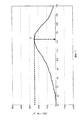
このモデルセルに対Li電位4.8Vで15時間定電流定電圧充電(対Li電位で4.8Vまで0.3C相当の電流で充電を行なった後、直ちに4.8V定電圧充電に移行し、充電開始からの総時間が15時間となったところで充電を停止する)を施した後、2時間放置した。このモデルセルから取り出した正極をメチルエチルカーボネート(MEC)に5分浸漬して洗浄し、アルゴンガス雰囲気で重量が1.5mgとなる大きさに打ち抜いた。次いで、打ち抜いた正極を容量15マイクロリットルのアルミ製密封容器に収容した後、エチレンカーボネート(EC)とメチルエチルカーボネート(MEC)を体積比(EC:MEC)が1:2になるように混合した非水溶媒に1MのLiPF6が溶解された測定用非水電解液3μLを滴下した。このサンプルについて、密封系の示差走査熱量計測定(装置名:セイコーインスツルメンツ社製 SSC5200H,DSC220)で25℃から5℃/分で昇温し、得られたDSCチャートのうち実施例1についてのものを図7に示す。図7から、実施例1の正極では、最初の発熱ピークの最高点が50〜155℃の温度区間に現れ、この発熱ピークの最高点Pが240mW/gであることを理解できる。実施例2〜5及び比較例1〜2の正極についても、それぞれのDSCチャートから最初の発熱ピークの最高点が50〜155℃の温度区間に現れ、この発熱ピークの最高点が下記表1に示す値であることを確認した。 This model cell was charged at a constant current / constant voltage for 15 hours at a Li potential of 4.8V (after charging at a current equivalent to 0.3C up to 4.8V at the potential of Li), it immediately shifted to 4.8V constant voltage charging. The charging was stopped when the total time from the start of charging reached 15 hours), and then left for 2 hours. The positive electrode taken out from this model cell was washed by immersing in methyl ethyl carbonate (MEC) for 5 minutes, and punched out to a size of 1.5 mg in an argon gas atmosphere. Next, after the punched positive electrode was accommodated in an aluminum sealed container having a capacity of 15 microliters, ethylene carbonate (EC) and methyl ethyl carbonate (MEC) were mixed so that the volume ratio (EC: MEC) was 1: 2. 3 μL of a nonaqueous electrolytic solution for measurement in which 1M LiPF 6 was dissolved in a nonaqueous solvent was dropped. About this sample, the temperature was increased from 25 ° C. to 5 ° C./min by differential scanning calorimetry measurement (device name: SSC5200H, DSC220 manufactured by Seiko Instruments Inc.) of the sealed system. Is shown in FIG. From FIG. 7, it can be understood that in the positive electrode of Example 1, the highest peak of the first exothermic peak appears in the temperature interval of 50 to 155 ° C., and the highest point P of the exothermic peak is 240 mW / g. For the positive electrodes of Examples 2 to 5 and Comparative Examples 1 and 2, the highest point of the first exothermic peak appears in the temperature range of 50 to 155 ° C. from each DSC chart, and the highest point of the exothermic peak is shown in Table 1 below. It was confirmed that the value was shown.
なお、図7は、ベースラインを図のX軸に揃えるために若干の傾き補正がなされた後の状態のものである。 FIG. 7 shows a state after a slight inclination correction is performed in order to align the baseline with the X axis in the figure.
実施例1〜5及び比較例1〜2の電池について、以下に説明する方法で低温放電特性を測定し、その結果を下記表1に示す。 About the battery of Examples 1-5 and Comparative Examples 1-2, the low-temperature discharge characteristic was measured by the method demonstrated below, and the result is shown in following Table 1.
(低温放電特性)
各二次電池について、1Cの電流で4.2Vの定電流・定電圧充電を3時間行った後、−20℃で1時間放置し、次いで−20℃の低温環境下で放電レート1C、放電終止電圧3.0Vの条件で放電させた場合の放電容量を測定した。得られた低温放電容量を、室温において同条件で放電した場合の放電容量を100%として表し、その結果を−20℃放電容量維持率として下記表1に示す。また、表1には、室温での放電容量も併記する。

Each secondary battery was charged with a constant current / constant voltage of 4.2 V at a current of 1 C for 3 hours, left at -20 ° C. for 1 hour, and then discharged at a low temperature environment of −20 ° C. with a discharge rate of 1 C. The discharge capacity when discharged under the condition of a final voltage of 3.0 V was measured. The obtained low-temperature discharge capacity is expressed as 100% of the discharge capacity when discharged under the same conditions at room temperature, and the result is shown in Table 1 below as the −20 ° C. discharge capacity retention rate. Table 1 also shows the discharge capacity at room temperature.
表1から明らかなように、実施例1〜5の二次電池は、室温で十分な放電容量が得られ、かつ−20℃での低温容量維持率も高いことが理解できる。 As is clear from Table 1, it can be understood that the secondary batteries of Examples 1 to 5 have a sufficient discharge capacity at room temperature and a high low-temperature capacity maintenance rate at −20 ° C.
これに対し、比較例1の二次電池と、比較例2の二次電池は、実施例1〜5の二次電池に比べて−20℃での低温容量維持率が低かった。比較例2の結果から、Liのモル比が1.01〜1.02の範囲から外れた場合には、焼成条件を調整して平均結晶子サイズを820〜1020Åの範囲に設定しても、低温放電特性が改善されないことがわかる。 On the other hand, the secondary battery of Comparative Example 1 and the secondary battery of Comparative Example 2 had a low low temperature capacity retention rate at −20 ° C. compared to the secondary batteries of Examples 1 to 5. From the result of Comparative Example 2, when the molar ratio of Li deviates from the range of 1.01 to 1.02, even if the firing condition is adjusted and the average crystallite size is set to the range of 820 to 1020%, It can be seen that the low temperature discharge characteristics are not improved.
前述した実施例では、DSCによる発熱ピーク測定用の非水電解液と、実際のセルに注入する非水電解液の組成を同じにしたが、実際のセルに注入する非水電解液の組成は、測定用非水電解液と異なっていても良い。実際のセルに注入する非水電解液として、例えば、エチレンカーボネート(EC)及びγ−ブチロラクトンを含む非水溶媒にLiPF6またはLiBF4を溶解させたものを使用することができる。 In the embodiment described above, the composition of the non-aqueous electrolyte for exothermic peak measurement by DSC and the non-aqueous electrolyte injected into the actual cell is the same, but the composition of the non-aqueous electrolyte injected into the actual cell is It may be different from the non-aqueous electrolyte for measurement. As a non-aqueous electrolyte to be injected into an actual cell, for example, a solution obtained by dissolving LiPF 6 or LiBF 4 in a non-aqueous solvent containing ethylene carbonate (EC) and γ-butyrolactone can be used.
なお、本発明は上記実施形態そのままに限定されるものではなく、実施段階ではその要旨を逸脱しない範囲で構成要素を変形して具体化できる。また、上記実施形態に開示されている複数の構成要素の適宜な組み合わせにより、種々の発明を形成できる。例えば、実施形態に示される全構成要素から幾つかの構成要素を削除してもよい。さらに、異なる実施形態にわたる構成要素を適宜組み合わせてもよい。 Note that the present invention is not limited to the above-described embodiment as it is, and can be embodied by modifying the components without departing from the scope of the invention in the implementation stage. In addition, various inventions can be formed by appropriately combining a plurality of components disclosed in the embodiment. For example, some components may be deleted from all the components shown in the embodiment. Furthermore, constituent elements over different embodiments may be appropriately combined.
1…容器本体、2…電極群、3…正極、4…負極、5…セパレータ、6…蓋板、7…外部保護層、8…内部保護層、9…金属層、10…正極端子、11…負極端子。
DESCRIPTION OF
Claims (2)
前記正極は、充電後、エチレンカーボネート(EC)とメチルエチルカーボネート(MEC)を体積比(EC:MEC)が1:2になるように混合した非水溶媒に1MのLiPF6を溶解させたものと密封系の示差走査熱量測定にて25℃から5℃/分で昇温した際に最初の発熱ピークの最高点が50℃〜155℃の区間に現れ、前記発熱ピークの最高点が320mW/g以下であることを特徴とする非水電解質電池。 A non-aqueous electrolyte battery comprising a positive electrode, a negative electrode, and a non-aqueous electrolyte,
The positive electrode is obtained by dissolving 1M LiPF 6 in a non-aqueous solvent in which ethylene carbonate (EC) and methyl ethyl carbonate (MEC) are mixed so that the volume ratio (EC: MEC) is 1: 2 after charging. When the temperature is raised from 25 ° C. to 5 ° C./min in differential scanning calorimetry of the sealed system, the highest peak of the first exothermic peak appears in the section of 50 ° C. to 155 ° C., and the highest peak of the exothermic peak is 320 mW / A non-aqueous electrolyte battery characterized by having a g or less.
Priority Applications (1)
| Application Number | Priority Date | Filing Date | Title |
|---|---|---|---|
| JP2004150481A JP2005332707A (en) | 2004-05-20 | 2004-05-20 | Positive electrode for non-aqueous electrolyte battery and non-aqueous electrolyte battery |
Applications Claiming Priority (1)
| Application Number | Priority Date | Filing Date | Title |
|---|---|---|---|
| JP2004150481A JP2005332707A (en) | 2004-05-20 | 2004-05-20 | Positive electrode for non-aqueous electrolyte battery and non-aqueous electrolyte battery |
Publications (1)
| Publication Number | Publication Date |
|---|---|
| JP2005332707A true JP2005332707A (en) | 2005-12-02 |
Family
ID=35487195
Family Applications (1)
| Application Number | Title | Priority Date | Filing Date |
|---|---|---|---|
| JP2004150481A Pending JP2005332707A (en) | 2004-05-20 | 2004-05-20 | Positive electrode for non-aqueous electrolyte battery and non-aqueous electrolyte battery |
Country Status (1)
| Country | Link |
|---|---|
| JP (1) | JP2005332707A (en) |
Cited By (27)
| Publication number | Priority date | Publication date | Assignee | Title |
|---|---|---|---|---|
| WO2011108654A1 (en) * | 2010-03-04 | 2011-09-09 | Jx日鉱日石金属株式会社 | Positive electrode active material for lithium-ion batteries, positive electrode for lithium-ion batteries, and lithium-ion battery |
| WO2011108656A1 (en) * | 2010-03-04 | 2011-09-09 | Jx日鉱日石金属株式会社 | Positive electrode active material for lithium-ion batteries, positive electrode for lithium-ion batteries, and lithium-ion battery |
| WO2011108652A1 (en) * | 2010-03-04 | 2011-09-09 | Jx日鉱日石金属株式会社 | Positive electrode active material for lithium ion battery, positive electrode for lithium ion battery, and lithium ion battery |
| US20110236751A1 (en) * | 2010-03-26 | 2011-09-29 | Shabab Amiruddin | High voltage battery formation protocols and control of charging and discharging for desirable long term cycling performance |
| US8623551B2 (en) | 2010-03-05 | 2014-01-07 | Jx Nippon Mining & Metals Corporation | Positive-electrode active material for lithium ion battery, positive electrode for lithium ion battery, and lithium ion battery |
| US8748041B2 (en) | 2009-03-31 | 2014-06-10 | Jx Nippon Mining & Metals Corporation | Positive electrode active material for lithium ion battery |
| US8993177B2 (en) | 2009-12-04 | 2015-03-31 | Envia Systems, Inc. | Lithium ion battery with high voltage electrolytes and additives |
| US8993160B2 (en) | 2009-12-18 | 2015-03-31 | Jx Nippon Mining & Metals Corporation | Positive electrode for lithium ion battery, method for producing said positive electrode, and lithium ion battery |
| US9090481B2 (en) | 2010-03-04 | 2015-07-28 | Jx Nippon Mining & Metals Corporation | Positive electrode active material for lithium-ion battery, positive electrode for lithium-ion battery, and lithium-ion battery |
| US9118076B2 (en) | 2010-02-05 | 2015-08-25 | Jx Nippon Mining & Metals Corporation | Positive electrode active material for lithium ion battery, positive electrode for lithium ion battery and lithium ion battery |
| US9159990B2 (en) | 2011-08-19 | 2015-10-13 | Envia Systems, Inc. | High capacity lithium ion battery formation protocol and corresponding batteries |
| US9214676B2 (en) | 2011-03-31 | 2015-12-15 | Jx Nippon Mining & Metals Corporation | Positive electrode active material for lithium ion batteries, positive electrode for lithium ion batteries, and lithium ion battery |
| US9216913B2 (en) | 2010-03-04 | 2015-12-22 | Jx Nippon Mining & Metals Corporation | Positive electrode active substance for lithium ion batteries, positive electrode for lithium ion batteries, and lithium ion battery |
| US9221693B2 (en) | 2011-03-29 | 2015-12-29 | Jx Nippon Mining & Metals Corporation | Method for producing positive electrode active material for lithium ion batteries and positive electrode active material for lithium ion batteries |
| US9224514B2 (en) | 2012-01-26 | 2015-12-29 | Jx Nippon Mining & Metals Corporation | Cathode active material for lithium ion battery, cathode for lithium ion battery, and lithium ion battery |
| US9224515B2 (en) | 2012-01-26 | 2015-12-29 | Jx Nippon Mining & Metals Coporation | Cathode active material for lithium ion battery, cathode for lithium ion battery, and lithium ion battery |
| US9225020B2 (en) | 2010-03-04 | 2015-12-29 | Jx Nippon Mining & Metals Corporation | Positive electrode active substance for lithium ion batteries, positive electrode for lithium ion batteries, and lithium ion battery |
| US9231249B2 (en) | 2010-02-05 | 2016-01-05 | Jx Nippon Mining & Metals Corporation | Positive electrode active material for lithium ion battery, positive electrode for lithium ion battery, and lithium ion battery |
| US9240594B2 (en) | 2010-03-04 | 2016-01-19 | Jx Nippon Mining & Metals Corporation | Positive electrode active substance for lithium ion batteries, positive electrode for lithium ion batteries, and lithium ion battery |
| US9263732B2 (en) | 2009-12-22 | 2016-02-16 | Jx Nippon Mining & Metals Corporation | Positive electrode active material for lithium-ion battery, positive electrode for a lithium-ion battery, lithium-ion battery using same, and precursor to a positive electrode active material for a lithium-ion battery |
| US9327996B2 (en) | 2011-01-21 | 2016-05-03 | Jx Nippon Mining & Metals Corporation | Method for producing positive electrode active material for lithium ion battery and positive electrode active material for lithium ion battery |
| US9911518B2 (en) | 2012-09-28 | 2018-03-06 | Jx Nippon Mining & Metals Corporation | Cathode active material for lithium-ion battery, cathode for lithium-ion battery and lithium-ion battery |
| US10122012B2 (en) | 2010-12-03 | 2018-11-06 | Jx Nippon Mining & Metals Corporation | Positive electrode active material for lithium-ion battery, a positive electrode for lithium-ion battery, and lithium-ion battery |
| WO2019099918A3 (en) * | 2017-11-17 | 2019-07-11 | Maxwell Technologies, Inc. | Non-aqueous solvent electrolyte formulations for energy storage devices |
| US10411299B2 (en) | 2013-08-02 | 2019-09-10 | Zenlabs Energy, Inc. | Electrolytes for stable cycling of high capacity lithium based batteries |
| US11973178B2 (en) | 2019-06-26 | 2024-04-30 | Ionblox, Inc. | Lithium ion cells with high performance electrolyte and silicon oxide active materials achieving very long cycle life performance |
| US12355079B2 (en) | 2020-07-02 | 2025-07-08 | Ionblox, Inc. | Lithium ion cells with silicon based active materials and negative electrodes with water-based binders having good adhesion and cohesion |
-
2004
- 2004-05-20 JP JP2004150481A patent/JP2005332707A/en active Pending
Cited By (39)
| Publication number | Priority date | Publication date | Assignee | Title |
|---|---|---|---|---|
| US8748041B2 (en) | 2009-03-31 | 2014-06-10 | Jx Nippon Mining & Metals Corporation | Positive electrode active material for lithium ion battery |
| US8993177B2 (en) | 2009-12-04 | 2015-03-31 | Envia Systems, Inc. | Lithium ion battery with high voltage electrolytes and additives |
| US8993160B2 (en) | 2009-12-18 | 2015-03-31 | Jx Nippon Mining & Metals Corporation | Positive electrode for lithium ion battery, method for producing said positive electrode, and lithium ion battery |
| US9263732B2 (en) | 2009-12-22 | 2016-02-16 | Jx Nippon Mining & Metals Corporation | Positive electrode active material for lithium-ion battery, positive electrode for a lithium-ion battery, lithium-ion battery using same, and precursor to a positive electrode active material for a lithium-ion battery |
| US9231249B2 (en) | 2010-02-05 | 2016-01-05 | Jx Nippon Mining & Metals Corporation | Positive electrode active material for lithium ion battery, positive electrode for lithium ion battery, and lithium ion battery |
| US9118076B2 (en) | 2010-02-05 | 2015-08-25 | Jx Nippon Mining & Metals Corporation | Positive electrode active material for lithium ion battery, positive electrode for lithium ion battery and lithium ion battery |
| WO2011108654A1 (en) * | 2010-03-04 | 2011-09-09 | Jx日鉱日石金属株式会社 | Positive electrode active material for lithium-ion batteries, positive electrode for lithium-ion batteries, and lithium-ion battery |
| JP5934089B2 (en) * | 2010-03-04 | 2016-06-15 | Jx金属株式会社 | Positive electrode active material for lithium ion battery, positive electrode for lithium ion battery, and lithium ion battery |
| WO2011108656A1 (en) * | 2010-03-04 | 2011-09-09 | Jx日鉱日石金属株式会社 | Positive electrode active material for lithium-ion batteries, positive electrode for lithium-ion batteries, and lithium-ion battery |
| JPWO2011108652A1 (en) * | 2010-03-04 | 2013-06-27 | Jx日鉱日石金属株式会社 | Positive electrode active material for lithium ion battery, positive electrode for lithium ion battery, and lithium ion battery |
| CN102782910A (en) * | 2010-03-04 | 2012-11-14 | Jx日矿日石金属株式会社 | Positive electrode active material for lithium ion battery, positive electrode for lithium ion battery, and lithium ion battery |
| CN102782910B (en) * | 2010-03-04 | 2015-06-24 | Jx日矿日石金属株式会社 | Positive electrode active material for lithium ion battery, positive electrode for lithium ion battery, and lithium ion battery |
| US9090481B2 (en) | 2010-03-04 | 2015-07-28 | Jx Nippon Mining & Metals Corporation | Positive electrode active material for lithium-ion battery, positive electrode for lithium-ion battery, and lithium-ion battery |
| US9240594B2 (en) | 2010-03-04 | 2016-01-19 | Jx Nippon Mining & Metals Corporation | Positive electrode active substance for lithium ion batteries, positive electrode for lithium ion batteries, and lithium ion battery |
| WO2011108652A1 (en) * | 2010-03-04 | 2011-09-09 | Jx日鉱日石金属株式会社 | Positive electrode active material for lithium ion battery, positive electrode for lithium ion battery, and lithium ion battery |
| US9225020B2 (en) | 2010-03-04 | 2015-12-29 | Jx Nippon Mining & Metals Corporation | Positive electrode active substance for lithium ion batteries, positive electrode for lithium ion batteries, and lithium ion battery |
| US9216913B2 (en) | 2010-03-04 | 2015-12-22 | Jx Nippon Mining & Metals Corporation | Positive electrode active substance for lithium ion batteries, positive electrode for lithium ion batteries, and lithium ion battery |
| JP5934088B2 (en) * | 2010-03-04 | 2016-06-15 | Jx金属株式会社 | Positive electrode active material for lithium ion battery, positive electrode for lithium ion battery, and lithium ion battery |
| US8623551B2 (en) | 2010-03-05 | 2014-01-07 | Jx Nippon Mining & Metals Corporation | Positive-electrode active material for lithium ion battery, positive electrode for lithium ion battery, and lithium ion battery |
| US20110236751A1 (en) * | 2010-03-26 | 2011-09-29 | Shabab Amiruddin | High voltage battery formation protocols and control of charging and discharging for desirable long term cycling performance |
| US8765306B2 (en) * | 2010-03-26 | 2014-07-01 | Envia Systems, Inc. | High voltage battery formation protocols and control of charging and discharging for desirable long term cycling performance |
| US10122012B2 (en) | 2010-12-03 | 2018-11-06 | Jx Nippon Mining & Metals Corporation | Positive electrode active material for lithium-ion battery, a positive electrode for lithium-ion battery, and lithium-ion battery |
| US9327996B2 (en) | 2011-01-21 | 2016-05-03 | Jx Nippon Mining & Metals Corporation | Method for producing positive electrode active material for lithium ion battery and positive electrode active material for lithium ion battery |
| US9221693B2 (en) | 2011-03-29 | 2015-12-29 | Jx Nippon Mining & Metals Corporation | Method for producing positive electrode active material for lithium ion batteries and positive electrode active material for lithium ion batteries |
| US9214676B2 (en) | 2011-03-31 | 2015-12-15 | Jx Nippon Mining & Metals Corporation | Positive electrode active material for lithium ion batteries, positive electrode for lithium ion batteries, and lithium ion battery |
| US9553301B2 (en) | 2011-08-19 | 2017-01-24 | Envia Systems, Inc. | High capacity lithium ion battery formation protocol and corresponding batteries |
| US9159990B2 (en) | 2011-08-19 | 2015-10-13 | Envia Systems, Inc. | High capacity lithium ion battery formation protocol and corresponding batteries |
| US9224514B2 (en) | 2012-01-26 | 2015-12-29 | Jx Nippon Mining & Metals Corporation | Cathode active material for lithium ion battery, cathode for lithium ion battery, and lithium ion battery |
| US9224515B2 (en) | 2012-01-26 | 2015-12-29 | Jx Nippon Mining & Metals Coporation | Cathode active material for lithium ion battery, cathode for lithium ion battery, and lithium ion battery |
| US9911518B2 (en) | 2012-09-28 | 2018-03-06 | Jx Nippon Mining & Metals Corporation | Cathode active material for lithium-ion battery, cathode for lithium-ion battery and lithium-ion battery |
| US11121407B2 (en) | 2013-08-02 | 2021-09-14 | Zenlabs Energy, Inc. | Electrolytes for stable cycling of high capacity lithium based batteries |
| US11894518B2 (en) | 2013-08-02 | 2024-02-06 | Zenlabs Energy, Inc. | Electrolytes for stable cycling of high capacity lithium based batteries |
| US10411299B2 (en) | 2013-08-02 | 2019-09-10 | Zenlabs Energy, Inc. | Electrolytes for stable cycling of high capacity lithium based batteries |
| JP2021503692A (en) * | 2017-11-17 | 2021-02-12 | マックスウェル テクノロジーズ インコーポレイテッド | Non-aqueous solvent electrolyte composition for energy storage equipment |
| WO2019099918A3 (en) * | 2017-11-17 | 2019-07-11 | Maxwell Technologies, Inc. | Non-aqueous solvent electrolyte formulations for energy storage devices |
| JP7428644B2 (en) | 2017-11-17 | 2024-02-06 | テスラ・インコーポレーテッド | Non-aqueous solvent electrolyte compositions for energy storage devices |
| US12500272B2 (en) | 2017-11-17 | 2025-12-16 | Tesla, Inc. | Non-aqueous solvent electrolyte formulations for energy storage devices |
| US11973178B2 (en) | 2019-06-26 | 2024-04-30 | Ionblox, Inc. | Lithium ion cells with high performance electrolyte and silicon oxide active materials achieving very long cycle life performance |
| US12355079B2 (en) | 2020-07-02 | 2025-07-08 | Ionblox, Inc. | Lithium ion cells with silicon based active materials and negative electrodes with water-based binders having good adhesion and cohesion |
Similar Documents
| Publication | Publication Date | Title |
|---|---|---|
| JP2005332707A (en) | Positive electrode for non-aqueous electrolyte battery and non-aqueous electrolyte battery | |
| JP4504074B2 (en) | Positive electrode active material for non-aqueous electrolyte battery, positive electrode and non-aqueous electrolyte battery | |
| CN1127774C (en) | Nonaqueous electrolyte secondary battery | |
| US11784314B2 (en) | Negative electrode for lithium secondary battery and lithium secondary battery including the same | |
| JP3868231B2 (en) | Carbon material, negative electrode for lithium ion secondary battery and lithium ion secondary battery | |
| US20090191458A1 (en) | Porous network negative electrodes for non-aqueous electrolyte secondary battery | |
| EP3404751B1 (en) | Positive electrode | |
| JP2010080407A (en) | Positive electrode active material, positive electrode, and non-aqueous electrolyte secondary battery | |
| JP4595145B2 (en) | Non-aqueous electrolyte battery | |
| CN101481109A (en) | Anode active material, anode, battery, and method of manufacturing anode | |
| JPWO2017057123A1 (en) | Negative electrode for lithium ion secondary battery and lithium ion secondary battery | |
| CN112136232B (en) | Nonaqueous electrolyte secondary battery | |
| JP6607388B2 (en) | Positive electrode for lithium ion secondary battery and method for producing the same | |
| JP2009200043A (en) | Battery | |
| JPWO2018179934A1 (en) | Anode material and non-aqueous electrolyte secondary battery | |
| JP7788642B2 (en) | Positive electrode for non-aqueous electrolyte secondary battery and non-aqueous electrolyte secondary battery | |
| JP4513385B2 (en) | Negative electrode for secondary battery and secondary battery | |
| JP2013134921A (en) | Electrode for nonaqueous electrolyte secondary battery, and nonaqueous electrolyte secondary battery | |
| CN115039252A (en) | Negative electrode for nonaqueous electrolyte secondary battery and nonaqueous electrolyte secondary battery | |
| CN116762185A (en) | Positive electrode for secondary battery and secondary battery | |
| JP2017183256A (en) | Nonaqueous electrolyte secondary battery | |
| CN107546375B (en) | Negative electrode material for non-aqueous electrolyte secondary battery and method for producing the same | |
| JP2006156021A (en) | Nonaqueous electrolyte secondary battery | |
| JP4833276B2 (en) | Carbon material for lithium battery and lithium battery | |
| JP6668848B2 (en) | Lithium ion secondary battery |