JP2005308665A - Heating resistor type flow meter - Google Patents
Heating resistor type flow meter Download PDFInfo
- Publication number
- JP2005308665A JP2005308665A JP2004129148A JP2004129148A JP2005308665A JP 2005308665 A JP2005308665 A JP 2005308665A JP 2004129148 A JP2004129148 A JP 2004129148A JP 2004129148 A JP2004129148 A JP 2004129148A JP 2005308665 A JP2005308665 A JP 2005308665A
- Authority
- JP
- Japan
- Prior art keywords
- heater
- flow rate
- signal
- temperature
- circuit
- Prior art date
- Legal status (The legal status is an assumption and is not a legal conclusion. Google has not performed a legal analysis and makes no representation as to the accuracy of the status listed.)
- Pending
Links
Images


Landscapes
- Measuring Volume Flow (AREA)
Abstract
Description
本発明は、気体の流量を計測する流量計、特に自動車のエンジンに吸入される空気流量を検出するに適した空気流量計に関わるものである。 The present invention relates to a flow meter for measuring a gas flow rate, and more particularly to an air flow meter suitable for detecting an air flow rate taken into an automobile engine.
自動車のエンジン吸入空気流量計の従来例としては、特許文献1に記載されているような発熱抵抗体の過熱制御電流値を検出し、空気流量に変換する方式のものや、発熱抵抗体の上下流に配置された感温抵抗への熱影響を温度差信号として検出し、それをブリッジ回路の電圧として捕らえる方式が知られている。 As a conventional example of an automobile engine intake air flow meter, a method of detecting an overheat control current value of a heating resistor as described in Patent Document 1 and converting it to an air flow rate, A system is known in which a thermal effect on a temperature-sensitive resistor disposed downstream is detected as a temperature difference signal and captured as a voltage of a bridge circuit.
また、空気流量検出素子の故障診断方式としては、特許文献2に記載されているようなダイヤフラムが破壊していることを検出するための抵抗が配置され、その抵抗値から故障を診断する方法や、特許文献3に記載されているような検出素子に並列に固定抵抗を接続し、擬似的に出力を変化させる方法、また、特許文献4に記載されているようなエンジンシステム内での診断方法が提案されている。
In addition, as a failure diagnosis method of the air flow rate detection element, a resistor for detecting that the diaphragm is broken as described in
しかし、これらの従来例ではセンサの故障診断のために新たに抵抗を配置する必要があり、コスト的に満足できる方法ではなかった。また、検出素子の温度から抵抗値に変換する検出特性の診断が行えず、破壊に至らない軽度な特性変化に対しての考慮が十分ではなかった。更に、自己診断は空気流量が流れていない時のみにしかできず、通常動作時に発生した故障を流量計自身で判断することはできなかった。 However, in these conventional examples, it is necessary to newly arrange a resistor for diagnosing a failure of the sensor, which is not a satisfactory method in terms of cost. Further, the detection characteristic for converting the temperature of the detection element into the resistance value cannot be diagnosed, and the consideration for the slight characteristic change that does not lead to destruction is not sufficient. Furthermore, the self-diagnosis can be performed only when the air flow rate is not flowing, and a failure occurring during normal operation cannot be determined by the flow meter itself.
解決しようとする問題点は、1つめに簡易な方法で且つ、通常動作時でも判断可能な空気流量検出素子の破壊を検出する方法の提示にある。また2つめに破壊に至らない軽微な特性変化に対して、特別な素子を追加せずに自己校正する手段を提示するものである。3つめに空気流量の検出素子の検出特性である温度に対する抵抗変化特性を確認できるようにしたものである。 The problem to be solved is to present a first simple method and a method for detecting the breakage of the air flow rate detecting element that can be determined even during normal operation. Secondly, a means for self-calibration without adding a special element to a slight characteristic change that does not cause destruction is presented. Thirdly, the resistance change characteristic with respect to temperature, which is the detection characteristic of the air flow rate detection element, can be confirmed.
本発明は、第1の課題を解決するために、通常動作時の破壊故障を検出するためにヒーター部の温度を制御するための加熱電流印加部の電圧、あるいはパルス幅変調のデューティーを検出し、最大または最小値が一定時間以上続く場合は破壊と判断するようにしたものである。 In order to solve the first problem, the present invention detects the voltage of the heating current application unit for controlling the temperature of the heater unit or the pulse width modulation duty in order to detect a breakdown failure during normal operation. When the maximum or minimum value continues for a certain time or more, it is determined that the device is broken.
また、第2の課題を解決するために、ヒーターの加熱温度を制御する定温度制御回路の動作を停止させた状態で、空気流量変換回路からの検出信号が規定の値に入っていることを検出し故障の有無を判断、あるいは自己校正するようにしたものである。 In order to solve the second problem, it is confirmed that the detection signal from the air flow rate conversion circuit is within a specified value while the operation of the constant temperature control circuit for controlling the heating temperature of the heater is stopped. It is detected and judged whether there is a failure, or self-calibrated.
更に、第3の課題を解決するために、空気流量検出素子の温度差検出抵抗の近傍に自己診断用ヒーター抵抗を付加し、そのヒーターのオン−オフ時の検出信号差から故障の有無を診断するようにしたものである。 Furthermore, in order to solve the third problem, a heater resistance for self-diagnosis is added in the vicinity of the temperature difference detection resistance of the air flow rate detection element, and the presence or absence of a failure is diagnosed from the detection signal difference when the heater is turned on and off. It is what you do.
本発明の空気流量計は検出素子の破壊故障を簡易な方法で動作中常に自己診断することができる。また、破壊に至らない軽微な特性変化については自己校正することができ、検出精度を向上させることができる。 The air flow meter of the present invention can always make a self-diagnosis during operation by a simple method for a breakdown failure of the detection element. In addition, a slight characteristic change that does not cause destruction can be self-calibrated, and detection accuracy can be improved.
以下、図面を用いて説明する。 Hereinafter, it demonstrates using drawing.
図1は、本発明の空気流量検出計のブロック構成を表したものである。発熱抵抗体であるヒーター9と空気温度を検出するためのコールドフィルム抵抗体10、及び固定抵抗
11,12がヒーターブリッジ回路1として接続され、被測定体の空気流通路内に配置される。また、ヒーターブリッジ回路1に隣接し、ヒーター9の上下流側に配置した感温抵抗体13,14,15,16の抵抗変化から空気流量を検出するように構成した温度差ブリッジ回路3も空気通路内に配置される。
FIG. 1 shows a block configuration of an air flow rate detector according to the present invention. A
ヒーターブリッジ回路1は定温度制御回路2によってヒーターの温度が一定値になるように加熱制御される。また、温度差ブリッジ回路3の検出信号は信号増幅出力調整回路4によって所定の入出力特性に増幅調整され、出力端子6から出力される。本空気流量計は電源端子5、及びグランド端子7によって駆動される。
The heater bridge circuit 1 is heated and controlled by a constant
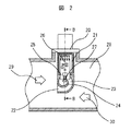
図2は、本発明の空気流量計の実装状態の断面構造を示したものである。本発明の空気流量計は通路管28内に挿入され、フランジ20によって通路管に固定される。通路管内には回路基板25の一部が納められる密閉室21と通路管内の空気を分流するバイパス通路22が曲がり通路管23を介してバイパス通路出口24から空気が排出される。このバイパス通路内の空気流量は回路基板25上に実装された空気流量検出素子27の周囲を通り、流量が抵抗変化に変換され検出される。検出された流量信号は回路基板上の回路素子26によって増幅され出力される。通常は流れ方向29に空気が流れているが、エンジンの脈動によって一次的には逆方向30にも空気が流れる。本発明の空気流量計はこの順逆両方向の空気を測定することができる。
FIG. 2 shows a cross-sectional structure of the air flow meter of the present invention in a mounted state. The air flow meter of the present invention is inserted into the
図3は本発明の第一の実施例で示したブロック構成を実現するための具体的回路構成を示したものである。ヒーターブリッジ回路1は一定温度に加熱制御されたヒーター9と空気温度検出するコールドフィルム抵抗体10と固定抵抗11,12がブリッジ状に接続されている。このブリッジ回路の信号をオペアンプ32と加熱電流を供給するためのトランジスタ31によって構成される定温度制御回路2によってヒーターの温度が一定になるようにフィードバック制御される。
FIG. 3 shows a specific circuit configuration for realizing the block configuration shown in the first embodiment of the present invention. In the heater bridge circuit 1, a
ヒーターの上下流側に配置された感温抵抗体13,14,15,16が温度差ブリッジ回路3を形成し、空気流量に応じた電圧信号が出力される。この温度差出力信号がオペアンプ33,34と抵抗36,37,38,39によってそれぞれバッファリングされ、オペアンプ35,抵抗40,41,42,43,44によって構成される信号増幅調整回路で所定の入出力特性に調整されて出力端子6から出力される。
The temperature
ここで後程図6にて説明する空気流量検出素子27のダイヤフラム67が突然破損した場合を想定する。定温度制御回路の制御電圧V1は、正常時にはある所定の電圧内で動作している。ところが破損等の故障時にはV1電圧は通常動作電圧よりも高いか或いは低い電圧に張り付く。この異常電圧を故障診断回路17内の抵抗53,56a,56b,58,トランジスタ55a,56b,OR回路57によって構成される判定回路で検出し、診断信号Dを出力する。この診断信号によって出力端子6は常に0Vに固定されるため、システムに異常を知らせることができる。
Here, it is assumed that the
図4は、ダイヤフラム破損異常時の動作を示したものである。検出する空気流量に応じて制御電圧V1と出力電圧Vout(端子7の電圧)が変化しているが、故障発生時には制御電圧V1が通常動作範囲外に張り付く。この電圧を検出した自己診断回路の出力DはHigh電圧(例えば5V)になり、このため、出力電圧は0Vに固定されることになり、システムに異常を伝えることができる。 FIG. 4 shows the operation when the diaphragm is broken. Although the control voltage V1 and the output voltage Vout (the voltage at the terminal 7) change according to the detected air flow rate, the control voltage V1 sticks out of the normal operating range when a failure occurs. The output D of the self-diagnosis circuit that detects this voltage becomes a high voltage (for example, 5 V), and therefore the output voltage is fixed to 0 V, and an abnormality can be transmitted to the system.
更に、自己校正・診断信号を印加することで、ゼロ点の自動校正や温度差ブリッジ回路側の診断を実現できる。これは、図3の自己診断回路17内のトランジスタ45,48,抵抗46,47,49,コンデンサ50によって構成されるアクティブ診断回路に診断信号が端子52から印加されることによって実現できる。
Furthermore, by applying a self-calibration / diagnosis signal, automatic calibration of the zero point and diagnosis on the temperature difference bridge circuit side can be realized. This can be realized by applying a diagnostic signal from a
図5の診断ダイヤグラムを用いてアクティブ自己診断動作を説明する。 The active self-diagnosis operation will be described using the diagnosis diagram of FIG.
自動車のエンジンキーがオフ時にコントロールユニットから供給される電源VCCはキーオフ診断のため供給され続けるようにする。その後一定時間後にシステムから自己診断開始信号DIAGが入力されると、ヒーター制御回路の動作は停止し、空気流量計の出力は温度差ブリッジ信号のゼロ点出力まで変化する。ここでゼロ点出力とは、ヒーター電流が流れていない状態(加熱されていない状態)であり、エンジンも停止状態のため、吸入空気も流れていない状態を示している。その後ゼロ点電圧を制御ユニットがサンプリングし、初期のゼロ点からのずれ量を演算し、変化している場合はそのずれ量を次回キーオン時に補正するために、ユニット内のメモリに記憶する。次回キーオン時にはこのメモリ内のゼロ点補正データを空気流量計の出力信号から差し引くことで、校正ができる。また、異常にずれ量が大きいときは故障と判断し、フェールセーフモードに移行し、次回キーオン時にドライバーに知らせるようにすることもできる。 The power VCC supplied from the control unit when the engine key of the automobile is off is kept supplied for key-off diagnosis. Thereafter, when a self-diagnosis start signal DIAG is input from the system after a certain period of time, the operation of the heater control circuit stops and the output of the air flow meter changes up to the zero point output of the temperature difference bridge signal. Here, the zero point output is a state in which no heater current flows (a state in which the heater current is not heated), and a state in which intake air does not flow because the engine is in a stopped state. Thereafter, the control unit samples the zero point voltage, calculates the amount of deviation from the initial zero point, and if it has changed, stores the amount of deviation in a memory in the unit for correction at the next key-on. At the next key-on, calibration can be performed by subtracting the zero point correction data in this memory from the output signal of the air flow meter. Further, when the amount of deviation is abnormally large, it is possible to determine that a failure has occurred and shift to the fail-safe mode so that the driver is notified at the next key-on.
更に時間が経過すると温度差ブリッジ回路の感温抵抗体近傍に配置された自己診断用ヒーター51がオンし、温度差ブリッジ回路に温度的なアンバランスを生じさせる。この時の出力信号変化量Aから、温度センサが正しく動作していることを検出し、正常か否かをシステム側の制御ユニット内で判断できる。
When the time further elapses, the self-
図6は、本発明に使われる空気流量検出素子の詳細を表したものである。空気流量検出素子60は、白金またはポリシリコン等で形成されるヒーター9,ヒーターの上下流側に配置されヒーターからの熱影響によって抵抗値が変化する感温抵抗体14,15,13,16,空気温度を検出するコールドフィルム抵抗体10、それらを電気的に外部へ伝達するための接続パッド65によって構成される。更に感温抵抗体の片側(図示では左側)には近接して自己診断用ヒーター51が配置される。コールドフィルム抵抗体と接続パッド以外の素子はすべて基板裏面がエッチングされたダイヤフラム67の上に配置されている。以上のような構成とすることで自己診断機能をもった空気流量計を実現できる。
FIG. 6 shows details of the air flow rate detecting element used in the present invention. The air flow
図7は本発明の他の回路実施例を示したものである。 FIG. 7 shows another circuit embodiment of the present invention.
ヒーターブリッジ回路1と温度差ブリッジ回路3の構成は図3と同様であるが、ヒーターの定温度制御回路2と出力調整回路4、及び自己診断回路17をデジタル回路で構成した場合の例を示す。ヒータ−の加熱制御は制御ブリッジ回路の検出信号をコンパレータ
70に入力し、デジタル信号に変化される。これをPI制御回路71に入力し、PWM回路でパルス幅信号に変換し、ドライバー73によってオン−オフ制御されることでヒーターの加熱温度が一定値になるように制御する。
The configurations of the heater bridge circuit 1 and the temperature
一方、温度差ブリッジ回路からの信号はA/D変換器74によってデジタル信号に変換され、DSP75によって演算処理され、これをD/A変換器76によってアナログ信号に戻して出力端子6から出力される。DSPではROMに記憶されたプログラムと補正データに基づいて所定の特性に補正演算される。
On the other hand, the signal from the temperature difference bridge circuit is converted into a digital signal by the A /
このような構成のデジタル補正型の空気流量計の自己診断は以下のようにすることで実現できる。まず、ダイヤフラム破損等の以上が発生した場合、ヒーターの加熱制御信号であるPWM信号を自己診断回路78で判断し異常と判断した場合にはDSPに信号を送ることで出力をフェールセーフ電圧に固定することでユニットに異常を伝えることができる。
Self-diagnosis of the digital correction type air flow meter having such a configuration can be realized as follows. First, if a diaphragm breakage or the like occurs, the PWM signal, which is the heating control signal of the heater, is judged by the self-
また、アクテイブ校正と温度差信号の診断は、自己診断信号52が印加されると、抵抗79とトランジスタ83,84を介してトランジスタ80がオフ動作となり、ヒーターの加熱電流がシャットダウンされる。この時の出力信号をモニターすることで自己校正と自己診断がアナログ回路の場合と同様に実施できる。また、その後、FF回路81によって遅延された診断信号がドライバー82を駆動し、温度差ブリッジ回路の感温抵抗体の片側を過熱することで、同じくアナログ回路と同様に温度差ブリッジの自己診断と校正ができる。また、ユニット内で実施していた空気流量計の校正演算を、デジタル回路の場合は、比較的簡単に空気流量計の中で実現することができる。何故ならば流量計内部にDSPとメモリをもっているからである。
In the active calibration and temperature difference signal diagnosis, when the self-
空気流量を検出する装置、例えば飛行機や船舶、また空気以外の媒体、例えば水素等の流量検出装置で、高い信頼性を要求されるものに利用可能である。 The present invention can be used for a device that detects air flow rate, for example, an airplane, a ship, or a medium other than air, for example, a flow rate detection device for hydrogen or the like that requires high reliability.
1…ヒーターブリッジ回路、2…定温度制御回路、3…温度差ブリッジ回路、4…信号増幅出力調整回路、5…電源端子、6…出力端子、7…グランド端子、9…ヒーター、
10…コールドフィルム抵抗体、11,12…抵抗。
DESCRIPTION OF SYMBOLS 1 ... Heater bridge circuit, 2 ... Constant temperature control circuit, 3 ... Temperature difference bridge circuit, 4 ... Signal amplification output adjustment circuit, 5 ... Power supply terminal, 6 ... Output terminal, 7 ... Ground terminal, 9 ... Heater,
10 ... Cold film resistor, 11, 12 ... Resistance.
Claims (3)
定温度制御回路のPWM(パルス幅変調)信号かまたは制御電圧値を検出し、判定する自己校正回路を備えることを特徴とする流量計。 A heater that generates heat due to an electric current and a resistor that detects the ambient temperature, a constant temperature control circuit that controls the temperature of the heater to a constant value, and a resistance of a temperature sensing element arranged on the upstream and downstream sides of the heater A signal that has a flow rate conversion circuit that converts a flow rate signal into an electrical signal, and that amplifies the output signal of the flow rate conversion circuit to a predetermined signal level, capturing that the thermal effect from the heater changes according to the gas flow rate A flow meter with an amplifier circuit,
A flowmeter comprising a self-calibration circuit that detects and determines a PWM (pulse width modulation) signal or a control voltage value of a constant temperature control circuit.
流量変換回路の自己校正は、定温度制御回路の動作を停止した状態での流量変換回路の出力を用いることを特徴とする流量計。 A heater that generates heat due to an electric current and a resistor that detects the ambient temperature, a constant temperature control circuit that controls the temperature of the heater to a constant value, and a resistance of a temperature sensing element arranged on the upstream and downstream sides of the heater A signal that has a flow rate conversion circuit that converts a flow rate signal into an electrical signal, and that amplifies the output signal of the flow rate conversion circuit to a predetermined signal level, capturing that the thermal effect from the heater changes according to the gas flow rate A flow meter with an amplifier circuit,
A flowmeter characterized in that the self-calibration of the flow rate conversion circuit uses the output of the flow rate conversion circuit in a state where the operation of the constant temperature control circuit is stopped.
流量変換回路の自己校正は、感温素子に隣接して配置された自己診断用過熱素子に通電することによってなることを特徴とする流量計。
A heater that generates heat due to an electric current and a resistor that detects the ambient temperature, a constant temperature control circuit that controls the temperature of the heater to a constant value, and a resistance of a temperature sensing element arranged on the upstream and downstream sides of the heater A signal that has a flow rate conversion circuit that converts a flow rate signal into an electrical signal, and that amplifies the output signal of the flow rate conversion circuit to a predetermined signal level, capturing that the thermal effect from the heater changes according to the gas flow rate A flow meter with an amplifier circuit,
The flowmeter is characterized in that self-calibration of the flow rate conversion circuit is performed by energizing a self-diagnostic overheating element arranged adjacent to the temperature-sensitive element.
Priority Applications (1)
| Application Number | Priority Date | Filing Date | Title |
|---|---|---|---|
| JP2004129148A JP2005308665A (en) | 2004-04-26 | 2004-04-26 | Heating resistor type flow meter |
Applications Claiming Priority (1)
| Application Number | Priority Date | Filing Date | Title |
|---|---|---|---|
| JP2004129148A JP2005308665A (en) | 2004-04-26 | 2004-04-26 | Heating resistor type flow meter |
Publications (1)
| Publication Number | Publication Date |
|---|---|
| JP2005308665A true JP2005308665A (en) | 2005-11-04 |
Family
ID=35437598
Family Applications (1)
| Application Number | Title | Priority Date | Filing Date |
|---|---|---|---|
| JP2004129148A Pending JP2005308665A (en) | 2004-04-26 | 2004-04-26 | Heating resistor type flow meter |
Country Status (1)
| Country | Link |
|---|---|
| JP (1) | JP2005308665A (en) |
Cited By (8)
| Publication number | Priority date | Publication date | Assignee | Title |
|---|---|---|---|---|
| JP2009229094A (en) * | 2008-03-19 | 2009-10-08 | Yamatake Corp | Thermal flowmeter |
| JP2011033424A (en) * | 2009-07-31 | 2011-02-17 | Hitachi Automotive Systems Ltd | Thermal type flowmeter with diagnostic function |
| JP2012058043A (en) * | 2010-09-08 | 2012-03-22 | Hitachi Automotive Systems Ltd | Gas flow rate measuring device |
| JP2012137388A (en) * | 2010-12-27 | 2012-07-19 | Denso Corp | Heat resistance type flow sensor and self-diagnosis method for the same |
| JP2015510132A (en) * | 2012-03-13 | 2015-04-02 | ピールブルク ゲゼルシャフト ミット ベシュレンクテル ハフツングPierburg GmbH | GAS MASS FLOW MEASURING DEVICE AND METHOD FOR RECALIBRATION OF THE DEVICE |
| JP2016200456A (en) * | 2015-04-08 | 2016-12-01 | 日本特殊陶業株式会社 | Fluid state detection device |
| JP2020012777A (en) * | 2018-07-20 | 2020-01-23 | アズビル株式会社 | Flow rate controller and zero point adjustment method |
| CN115060338A (en) * | 2021-03-08 | 2022-09-16 | 苏州原位芯片科技有限责任公司 | Flow sensor |
-
2004
- 2004-04-26 JP JP2004129148A patent/JP2005308665A/en active Pending
Cited By (9)
| Publication number | Priority date | Publication date | Assignee | Title |
|---|---|---|---|---|
| JP2009229094A (en) * | 2008-03-19 | 2009-10-08 | Yamatake Corp | Thermal flowmeter |
| JP2011033424A (en) * | 2009-07-31 | 2011-02-17 | Hitachi Automotive Systems Ltd | Thermal type flowmeter with diagnostic function |
| JP2012058043A (en) * | 2010-09-08 | 2012-03-22 | Hitachi Automotive Systems Ltd | Gas flow rate measuring device |
| JP2012137388A (en) * | 2010-12-27 | 2012-07-19 | Denso Corp | Heat resistance type flow sensor and self-diagnosis method for the same |
| JP2015510132A (en) * | 2012-03-13 | 2015-04-02 | ピールブルク ゲゼルシャフト ミット ベシュレンクテル ハフツングPierburg GmbH | GAS MASS FLOW MEASURING DEVICE AND METHOD FOR RECALIBRATION OF THE DEVICE |
| JP2016200456A (en) * | 2015-04-08 | 2016-12-01 | 日本特殊陶業株式会社 | Fluid state detection device |
| JP2020012777A (en) * | 2018-07-20 | 2020-01-23 | アズビル株式会社 | Flow rate controller and zero point adjustment method |
| JP7111539B2 (en) | 2018-07-20 | 2022-08-02 | アズビル株式会社 | Flow control device and zero point adjustment method |
| CN115060338A (en) * | 2021-03-08 | 2022-09-16 | 苏州原位芯片科技有限责任公司 | Flow sensor |
Similar Documents
| Publication | Publication Date | Title |
|---|---|---|
| US7607823B2 (en) | Leak detector comprising a self-heated thermistor control circuit | |
| JP5609827B2 (en) | Air flow measurement device | |
| JP2005534014A5 (en) | ||
| JP5961592B2 (en) | Thermal mass flow meter | |
| JP2005308665A (en) | Heating resistor type flow meter | |
| EP1657532A1 (en) | Thermal mass flow sensor | |
| US7467547B2 (en) | Fluid-measuring device and fluid-measuring method | |
| JP2012207925A (en) | Thermal air flowmeter | |
| JP5111180B2 (en) | Thermal flow meter | |
| JP3527657B2 (en) | Flow sensor failure determination apparatus and method | |
| JP5120289B2 (en) | Air flow measurement device | |
| JP2003302271A (en) | Flow measurement unit package and flow measurement unit using the same | |
| JP2010216906A (en) | Automobile-use flowmeter | |
| JP4309668B2 (en) | Thermal air flow measuring device and diagnostic method thereof | |
| WO2009032593A2 (en) | Self diagnostic measurement method to detect microbridge null drift and performance | |
| JP2009031014A (en) | Thermal gas mass flow meter | |
| JP3991161B2 (en) | Flow rate sensor | |
| JP3706283B2 (en) | Flow sensor circuit | |
| JP2004205376A (en) | Thermal mass flow sensor and gas combustion device | |
| JP2001066193A (en) | Evaluation circuit of thermocouple measurement signal | |
| JP5178264B2 (en) | Thermal flow meter | |
| JP5510311B2 (en) | Heating resistance type flow sensor and its self-diagnosis method | |
| JP3758031B2 (en) | Thermal flow meter | |
| JP2010237201A (en) | Vortex flow meter | |
| JP3473501B2 (en) | Thermal air flow meter |
Legal Events
| Date | Code | Title | Description |
|---|---|---|---|
| RD04 | Notification of resignation of power of attorney |
Free format text: JAPANESE INTERMEDIATE CODE: A7424 Effective date: 20060424 |
|
| A621 | Written request for application examination |
Free format text: JAPANESE INTERMEDIATE CODE: A621 Effective date: 20060726 |
|
| A977 | Report on retrieval |
Free format text: JAPANESE INTERMEDIATE CODE: A971007 Effective date: 20081205 |
|
| A131 | Notification of reasons for refusal |
Free format text: JAPANESE INTERMEDIATE CODE: A131 Effective date: 20081209 |
|
| A521 | Written amendment |
Free format text: JAPANESE INTERMEDIATE CODE: A523 Effective date: 20090209 |
|
| A131 | Notification of reasons for refusal |
Free format text: JAPANESE INTERMEDIATE CODE: A131 Effective date: 20090630 |
|
| A02 | Decision of refusal |
Free format text: JAPANESE INTERMEDIATE CODE: A02 Effective date: 20091027 |