JP2005212773A - Mounting system for bicycle wheel spoke - Google Patents
Mounting system for bicycle wheel spoke Download PDFInfo
- Publication number
- JP2005212773A JP2005212773A JP2005018761A JP2005018761A JP2005212773A JP 2005212773 A JP2005212773 A JP 2005212773A JP 2005018761 A JP2005018761 A JP 2005018761A JP 2005018761 A JP2005018761 A JP 2005018761A JP 2005212773 A JP2005212773 A JP 2005212773A
- Authority
- JP
- Japan
- Prior art keywords
- spoke
- spoke attachment
- attachment member
- hole
- seat
- Prior art date
- Legal status (The legal status is an assumption and is not a legal conclusion. Google has not performed a legal analysis and makes no representation as to the accuracy of the status listed.)
- Pending
Links
- 229910052782 aluminium Inorganic materials 0.000 claims description 9
- XAGFODPZIPBFFR-UHFFFAOYSA-N aluminium Chemical compound [Al] XAGFODPZIPBFFR-UHFFFAOYSA-N 0.000 claims description 9
- 229910000831 Steel Inorganic materials 0.000 claims description 7
- 239000010959 steel Substances 0.000 claims description 7
- 238000000034 method Methods 0.000 claims description 5
- 240000007643 Phytolacca americana Species 0.000 abstract 1
- DOSMHBDKKKMIEF-UHFFFAOYSA-N 2-[3-(diethylamino)-6-diethylazaniumylidenexanthen-9-yl]-5-[3-[3-[4-(1-methylindol-3-yl)-2,5-dioxopyrrol-3-yl]indol-1-yl]propylsulfamoyl]benzenesulfonate Chemical compound C1=CC(=[N+](CC)CC)C=C2OC3=CC(N(CC)CC)=CC=C3C(C=3C(=CC(=CC=3)S(=O)(=O)NCCCN3C4=CC=CC=C4C(C=4C(NC(=O)C=4C=4C5=CC=CC=C5N(C)C=4)=O)=C3)S([O-])(=O)=O)=C21 DOSMHBDKKKMIEF-UHFFFAOYSA-N 0.000 description 13
- 210000002445 nipple Anatomy 0.000 description 5
- 239000004033 plastic Substances 0.000 description 5
- 230000014509 gene expression Effects 0.000 description 4
- 238000005192 partition Methods 0.000 description 4
- 229920000049 Carbon (fiber) Polymers 0.000 description 3
- 239000011324 bead Substances 0.000 description 3
- 230000008901 benefit Effects 0.000 description 3
- 239000004917 carbon fiber Substances 0.000 description 3
- VNWKTOKETHGBQD-UHFFFAOYSA-N methane Chemical compound C VNWKTOKETHGBQD-UHFFFAOYSA-N 0.000 description 3
- 230000009471 action Effects 0.000 description 2
- 239000000956 alloy Substances 0.000 description 2
- 229910045601 alloy Inorganic materials 0.000 description 2
- 238000005266 casting Methods 0.000 description 2
- 238000003780 insertion Methods 0.000 description 2
- 230000037431 insertion Effects 0.000 description 2
- 239000000463 material Substances 0.000 description 2
- 239000000126 substance Substances 0.000 description 2
- FYYHWMGAXLPEAU-UHFFFAOYSA-N Magnesium Chemical compound [Mg] FYYHWMGAXLPEAU-UHFFFAOYSA-N 0.000 description 1
- 239000004677 Nylon Substances 0.000 description 1
- 230000033228 biological regulation Effects 0.000 description 1
- 230000015572 biosynthetic process Effects 0.000 description 1
- 238000003490 calendering Methods 0.000 description 1
- 230000007547 defect Effects 0.000 description 1
- 229920001971 elastomer Polymers 0.000 description 1
- 238000001125 extrusion Methods 0.000 description 1
- 239000011777 magnesium Substances 0.000 description 1
- 229910052749 magnesium Inorganic materials 0.000 description 1
- 230000014759 maintenance of location Effects 0.000 description 1
- 229910052751 metal Inorganic materials 0.000 description 1
- 239000002184 metal Substances 0.000 description 1
- 229920001778 nylon Polymers 0.000 description 1
- 230000002093 peripheral effect Effects 0.000 description 1
- 230000008569 process Effects 0.000 description 1
- 230000000750 progressive effect Effects 0.000 description 1
- 229920002379 silicone rubber Polymers 0.000 description 1
- 238000009721 upset forging Methods 0.000 description 1
- 239000013585 weight reducing agent Substances 0.000 description 1
Images


Classifications
-
- B—PERFORMING OPERATIONS; TRANSPORTING
- B60—VEHICLES IN GENERAL
- B60B—VEHICLE WHEELS; CASTORS; AXLES FOR WHEELS OR CASTORS; INCREASING WHEEL ADHESION
- B60B21/00—Rims
- B60B21/06—Rims characterised by means for attaching spokes, i.e. spoke seats
- B60B21/062—Rims characterised by means for attaching spokes, i.e. spoke seats for bicycles
-
- B—PERFORMING OPERATIONS; TRANSPORTING
- B60—VEHICLES IN GENERAL
- B60B—VEHICLE WHEELS; CASTORS; AXLES FOR WHEELS OR CASTORS; INCREASING WHEEL ADHESION
- B60B1/00—Spoked wheels; Spokes thereof
- B60B1/02—Wheels with wire or other tension spokes
- B60B1/04—Attaching spokes to rim or hub
- B60B1/041—Attaching spokes to rim or hub of bicycle wheels
-
- B—PERFORMING OPERATIONS; TRANSPORTING
- B60—VEHICLES IN GENERAL
- B60B—VEHICLE WHEELS; CASTORS; AXLES FOR WHEELS OR CASTORS; INCREASING WHEEL ADHESION
- B60B1/00—Spoked wheels; Spokes thereof
- B60B1/02—Wheels with wire or other tension spokes
- B60B1/04—Attaching spokes to rim or hub
- B60B1/043—Attaching spokes to rim
- B60B1/048—Attaching spokes to rim by the use of screws
-
- B—PERFORMING OPERATIONS; TRANSPORTING
- B60—VEHICLES IN GENERAL
- B60B—VEHICLE WHEELS; CASTORS; AXLES FOR WHEELS OR CASTORS; INCREASING WHEEL ADHESION
- B60B21/00—Rims
- B60B21/02—Rims characterised by transverse section
- B60B21/025—Rims characterised by transverse section the transverse section being hollow
-
- Y—GENERAL TAGGING OF NEW TECHNOLOGICAL DEVELOPMENTS; GENERAL TAGGING OF CROSS-SECTIONAL TECHNOLOGIES SPANNING OVER SEVERAL SECTIONS OF THE IPC; TECHNICAL SUBJECTS COVERED BY FORMER USPC CROSS-REFERENCE ART COLLECTIONS [XRACs] AND DIGESTS
- Y10—TECHNICAL SUBJECTS COVERED BY FORMER USPC
- Y10T—TECHNICAL SUBJECTS COVERED BY FORMER US CLASSIFICATION
- Y10T29/00—Metal working
- Y10T29/49—Method of mechanical manufacture
- Y10T29/49481—Wheel making
- Y10T29/49492—Land wheel
- Y10T29/49506—Tensioned spoke type wheel making
- Y10T29/49512—Tensioning spokes individually
Landscapes
- Engineering & Computer Science (AREA)
- Mechanical Engineering (AREA)
- Connection Of Plates (AREA)
- Motorcycle And Bicycle Frame (AREA)
- Tires In General (AREA)
- Automatic Cycles, And Cycles In General (AREA)
- Steering Devices For Bicycles And Motorcycles (AREA)
Abstract
Description
本発明は、自転車の車輪のスポークのための取付けシステムに関し、とくに自転車の車輪のためのスポーク取付け用部材、複数個のそのようなスポーク取付け用部材とともに使用すべく構成された自転車の車輪のリム、および複数個のそのようなスポーク取付け用部材ならびに他のスポーク取付け用部材を有する自転車の車輪に関する。 The present invention relates to a mounting system for spokes of a bicycle wheel, and more particularly to a spoke mounting member for a bicycle wheel, a bicycle wheel rim configured for use with a plurality of such spoke mounting members. And a plurality of such spoke attachment members as well as bicycle wheels having other spoke attachment members.
スポーク付きの自転車の車輪は、周囲のクラウンすなわちタイヤを組み付けるためのリム、自転車のフレームに回転可能に組み付けられる中央のハブ、およびリムとハブとの間を伸びる複数本のスポークを有している。 A spoked bicycle wheel has a rim for assembling the surrounding crown or tire, a central hub that is rotatably assembled to the bicycle frame, and a plurality of spokes extending between the rim and hub. .
自転車のスポークは、2つの端部を有する細長い本体を備えている。スポークをハブとリムとの間で引っ張って組み付けることができるよう、2つの端部のそれぞれが、細長い本体から横方向に張り出した頭部を有しており、あるいはねじを有している。通常は、スポークの一端は張り出した頭部を有しており、他端が雄ねじを有している。実際、この構成は、頭部が設けられてなるスポークの端部をそれぞれハブまたはリムの側に位置する適切な形状の着座部に係合させる一方で、ねじが設けられてなる端部をそれぞれリムまたはハブの側に位置する雌ねじが設けられた座孔へとねじ込み、このねじ込みの深さによって、組立工程および自転車の使用においてスポークの引っ張りを微調整することができるため、好ましい構成である。 Bicycle spokes have an elongated body with two ends. Each of the two ends has a head projecting laterally from the elongated body, or has a screw, so that the spoke can be pulled and assembled between the hub and the rim. Usually, one end of the spoke has an overhanging head and the other end has a male thread. In fact, this configuration allows the end of the spoke provided with the head to engage the seat of the appropriate shape located on the side of the hub or rim, respectively, while the end provided with the screw respectively This is a preferable configuration because it is screwed into a seat hole provided with a female screw located on the rim or hub side, and the depth of this screwing allows fine adjustment of the spoke pull in the assembly process and use of the bicycle.
広く使用されている第1の形式のスポークは、鋼で作られている。ねじ端は、2〜3mm程度の直径を有している。広く使用されている第2の形式のスポークは、アルミニウムで作られている。この場合、鋼製のスポークに等しい機械的強度の特性を有するため、ねじ端が4〜6mm程度の直径を有していなければならない。 A widely used first type of spoke is made of steel. The screw end has a diameter of about 2 to 3 mm. A widely used second type of spoke is made of aluminum. In this case, since it has the characteristic of mechanical strength equivalent to a steel spoke, the screw end must have a diameter of about 4 to 6 mm.
単溝の形状とされた自転車のリムが公知であり、この溝の側壁すなわちフィンとタイヤのビードとが、フィンから張り出したリップによって連結し、さらに溝の底部に、スポークを取付けるための複数の座孔が設けられている。このような形式のリムは構造的な剛性に乏しく、したがって横荷重による変形が大きい。 Bicycle rims having a single groove shape are known, and the side walls of the groove, i.e., the fin and the tire bead, are connected by a lip protruding from the fin, and a plurality of grooves for attaching spokes to the bottom of the groove. A seat hole is provided. Such a type of rim has poor structural rigidity and is therefore largely deformed by lateral loads.
構造的な剛性を向上させ、横荷重による変形を小さくするため、その断面を見ると、タイヤと連結するための半径方向外側の円周溝と、本質的に中空であって以下では「スポーク取付け室」と称する半径方向内側の円周状の本体部とが示される自転車のリムも、公知である。タイヤと連結するための溝と本体部とは、この分野および以下において「上部ブリッジ」と称される壁で区画されている。 To improve structural rigidity and reduce deformation due to lateral loads, the cross-sectional view shows a radially outer circumferential groove to connect to the tire, and is essentially hollow and is Bicycle rims are also known, which are shown with a radially inner circumferential body called "chamber". The groove for connecting to the tire and the main body are defined by a wall referred to as an “upper bridge” in this field and hereinafter.
溝が、タイヤとの結合にかんがみ、形状および公差について規格または規制の対象である一方、半径方向内側の領域は、車輪の軸に対する形状および配向が適切であるスポーク取付け面を提供できるのであれば、きわめてさまざまな構成をとることが可能である。 If the groove is subject to standardization or regulation for shape and tolerance in view of the connection with the tire, the radially inner area can provide a spoke mounting surface that is suitable for shape and orientation relative to the wheel axle. It is possible to take a wide variety of configurations.
この公知の第2の形式の自転車のリムの典型的な構成は、逆立ちしたAの字形の断面を有しており、すなわち、半径方向内側の本体部が、上部ブリッジ、2枚の側壁、および半径方向内側に位置し「下部ブリッジ」とも称される円周壁によって定められる単一の室から形成されている。この室は、本質的に矩形、すなわち側壁がリムの中央面に対して事実上平行である断面を有することができ、またリムの中央面に関して対称である本質的に台形、すなわち側壁が斜めになっている断面を有することができ、あるいは、非対称で本質的に台形、すなわち第1の側壁がリムの中央面と平行な面内に事実上延びており、第2の壁が斜めに延びている断面を有することができる。他の構成においては、半径方向内側の領域に、上部ブリッジと事実上平行または事実上垂直に延びる1つ以上の仕切り壁が設けられ、2つ以上の円周状のスポーク取付け室が定められている。 The typical configuration of this known second type bicycle rim has an inverted A-shaped cross section, i.e., the radially inner body comprises an upper bridge, two sidewalls, and It is formed from a single chamber defined by a circumferential wall located radially inward and also referred to as the “lower bridge”. This chamber may be essentially rectangular, i.e. having a cross-section whose side walls are substantially parallel to the central plane of the rim, and essentially trapezoidal, i.e. the side walls being oblique with respect to the central plane of the rim. Or asymmetric and essentially trapezoidal, i.e. the first side wall extends substantially in a plane parallel to the central plane of the rim and the second side extends diagonally. Can have a cross section. In another configuration, the radially inner region is provided with one or more partition walls extending substantially parallel or substantially perpendicular to the upper bridge, and two or more circumferential spoke attachment chambers are defined. Yes.
この形式のリムは、カーボン繊維の注型(例えば、特許文献1を参照されたい)によって製作することができ、あるいは、通常はアルミニウムで作られている金属製異形材を押し出し、カレンダ加工し、両端をつなぎ合わせることによって製作することができる。
本発明は、とくに上部ブリッジが設けられてなるリムに関するが、本発明によるスポーク取付け用部材を単溝のリムにおいて使用すること、ならびに車輪のハブにおいて使用することを除外するものではない。 The invention relates in particular to a rim provided with an upper bridge, but does not exclude the use of the spoke attachment element according to the invention in a single groove rim as well as in a wheel hub.
車輪のリムおよびハブの座孔は、それぞれにスポークのねじ端との係合のための雌ねじを備えることによって、あるいは、スポークの張り出し頭部のための着座部となるよう形状をスポークの張り出し頭部に合致させることによって、スポークを直接取付けるように構成することができる。しかしながら、スポーク取付け用部材をスポークとリムおよび/またはハブの座孔との間に配置して使用することが、より一般的である。 The wheel rim and hub seat holes are each provided with an internal thread for engagement with the threaded end of the spoke, or shaped to provide a seat for the spoke head. The spokes can be configured to be attached directly by matching the part. However, it is more common to use the spoke attachment member positioned between the spoke and the rim and / or hub seat.
単溝のリムにおいては、スポーク取付け用部材によるスポークの固定は、リムの円周の外側から行なわれ、すなわちタイヤ連結溝から行なわれる。 In the single groove rim, the spoke is fixed by the spoke attachment member from the outside of the circumference of the rim, that is, from the tire connecting groove.
一方、タイヤ連結溝と別個にスポーク取付け室を有する前述のリムにおいては、リムの円周方向外側からの座孔へのアクセスが、上部ブリッジの存在によって妨げられてしまう。 On the other hand, in the above-described rim having the spoke attachment chamber separately from the tire connection groove, access to the seat hole from the outer circumferential direction of the rim is hindered by the presence of the upper bridge.
それにもかかわらずスポークの固定が可能であるよう、例えば特許文献2、特許文献3、
特許文献4および特許文献5にいくつかの解決策が開示されており、スポーク取付け用部材が、リムの円周の内側から取付けられている。しかしながら、このような場合には、スポーク取付け用部材をリムに当接して機能することがないよう変更しなければならず、結果として、スポーク取付け用部材と着座部との間に追加の部品を配置する必要が生じ、さらに/あるいはリムにねじ座を形成する必要が生じる。さらに、本出願の優先権主張日時点においてはまだ公開されていないが、特許文献6に或る方法が開示されており、当接形式の取付け用部材の着座がスポーク取付け室の内側から行なわれ、締め込みは、座孔を貫いて延びる取付け用部材の軸部に働きかけることによってリムの半径方向内側から行なわれている。しかしながら、このような組み立て方法は、とくにスポークを交換する必要がある末端ユーザにとって、迅速かつ容易でないかもしれない。
Several solutions are disclosed in Patent Literature 4 and
したがって、チューブレス・タイヤの場合における上部ブリッジの完全性など他の要件が存在しないときには、例えばカンパニョーロ社(Campagnolo)の特許文献7に記載されているように、上部ブリッジに複数のアクセス開口を各スポーク取付け座に対して半径方向に設けることが、やはり好ましい。このようなアクセス開口によって、ねじ無しの座孔に当接して機能するスポーク取付け用部材を挿入することができ、スポークの取付けおよび張力の調節の際に、スポーク取付け用部材のスポークへのねじ込みおよび/またはスポーク取付け用部材の保持を行なうための工具を、接近させて導き入れることができる。この特許文献7においては、スポーク取付け用部材は概略的にのみ示されている。
このようなアクセス開口が設けられた複雑な断面の単溝リムへと取付けるため、ならびに車輪のハブへと取付けるため、当接して機能する2つの異なる形式のスポーク取付け用部材が知られている。 Two different types of spoke attachment members are known which function in abutment for attachment to complex grooved single groove rims provided with such access openings, as well as to wheel hubs.
第1の形式のスポーク取付け用部材は、以後の本明細書および特許請求の範囲において「軸棒(shank)形式のスポーク取付け用部材」と呼ばれ、この技術分野において「外側ニップル」とも称され、一方、第2の形式のスポーク取付け用部材は、以後の本明細書および特許請求の範囲において「ナット(nut)形式のスポーク取付け用部材」または短く「ナット」と呼ばれ、この技術分野において「内側ニップル」とも称される。 The first type of spoke attachment member will be referred to in the following specification and claims as a “shank type spoke attachment member” and also referred to in the art as an “outer nipple”. On the other hand, the second type of spoke attachment member is referred to hereinafter as “nut type spoke attachment member” or short “nut” in the present specification and claims. Also called “inner nipple”.
これら形式のスポーク取付け用部材を説明する前に、この技術分野において、上述のものと部分的に相容れない専門用語を使用するスポーク取付け用部材の分類法も使用されていることを、強調しておく価値がある。そのような分類法によれば、スポーク取付け用部材は、それらがスポークの張力の調節を可能にしている場合に「ニップル(nipple)」と称され、そうでない場合には「バレル(barrel)」と称される。 Before discussing these types of spoke attachment members, it is emphasized that the classification of spoke attachment members is also used in the art that uses terminology that is partially incompatible with the above. worth it. According to such a taxonomy, the spoke attachment members are referred to as “nipples” when they allow the spoke tension to be adjusted, otherwise “barrel”. It is called.
本明細書および特許請求の範囲において、「ニップル形式の接続」という表現は、とくにスポーク取付け用部材に関し、スポークを取付けるための孔が全体にわたってねじが設けられた貫通孔であり、あるいは行き止まりであろうと貫通孔であろうと、スポークのねじ長さよりも大きいねじ長さを有する孔であり、すなわちスポークのねじ込み深さを変化させることによってスポークの張力を変化させることができるという意味である。一方、「バレル形式の接続」という表現は、とくにスポーク取付け用部材に関し、スポークを取付けるための孔が、スポークのねじと等しい長さのねじを有するとともに通常は行き止まりであり、あるいはスポークの張り出した頭部を差込[バヨネット(bayonet)]状に
係合させるための切り欠き凹所を有していることを示す意味である。
In the present description and in the claims, the expression “nipple-type connection” refers in particular to a spoke attachment member, wherein the hole for attaching the spoke is a through-hole with an entire thread or a dead end. Whether it is a wax or a through hole, it is a hole having a thread length larger than the thread length of the spoke, that is, it means that the tension of the spoke can be changed by changing the screwing depth of the spoke. On the other hand, the expression “barrel-type connection” refers to a spoke attachment member, in particular, the hole for attaching the spoke has a screw of the same length as the spoke screw and is usually a dead end, or the spoke is overhanging. It means that it has a notch recess for engaging the head in the shape of a bayonet.
軸棒形式のスポーク取付け用部材は、横方向の寸法が座孔よりも大きい頭部、および横方向の寸法が座孔よりもわずかに小さい軸部を有しており、スポークのねじをねじ込むためにねじ孔が延びており、あるいはスポークの張り出した頭部とバヨネット状に係合するための孔が延びている。組み立てられた状態において、軸部が座孔を貫通する一方で、頭部と軸部の間の接続面が、座孔が設けられているリムの下部ブリッジまたはハブの壁面に当接し、スポークの引っ張り応力に対抗する。 The shaft rod type spoke mounting member has a head part whose lateral dimension is larger than the seat hole and a shaft part whose lateral dimension is slightly smaller than the seat hole, so that the spoke screw is screwed in. A screw hole is extended to the head, or a hole for engaging the protruding head of the spoke in a bayonet shape is extended. In the assembled state, while the shaft portion penetrates the seat hole, the connection surface between the head portion and the shaft portion abuts against the wall surface of the lower bridge or hub of the rim where the seat hole is provided, and the spoke Resists tensile stress.
軸棒形式のスポーク取付け用部材の場合には、リム側における組み立ては、通常、スポーク取付け用部材の軸部の端部を座孔に向け、スポークの端部を座孔に整列させ、リムの半径方向外側からスポーク取付け用部材の頭部へと工具を作用させることにより、スポーク取付け用部材およびスポークの相応する固定手段間の係合、すなわち例えばねじ込みや差込み係合を生じさせて行なわれる。 In the case of a shaft mounting type spoke mounting member, the assembly on the rim side is usually performed with the end of the spoke mounting member facing the seat hole and the end of the spoke aligned with the seat hole. This is done by applying a tool from the radially outer side to the head of the spoke attachment member, causing an engagement between the spoke attachment member and the corresponding fastening means of the spoke, i.e. for example screwing or plugging engagement.
軸棒形式のスポーク取付け用部材は、例えば特許文献8に示されている。このスポーク取付け用部材は、頭部および軸部を有する本体を有し、スポークのねじ端とのニップル形式の接続のため、雌ねじが設けられた貫通孔が横断している。この取付け用部材の頭部は、ボックス・レンチまたはソケット・レンチ形式の工具との係合のため六角形である。この取付け用部材の軸部は、同様に角ばっており、あるいは長手方向の溝を有する形状とされている。
自転車の使用時にスポークが緩むという傾向に対抗するため、特許文献8に開示の軸棒形式のスポーク取付け用部材においては、実質的に変形が可能な材料からなる孔付きの挿入物が、軸部のねじ孔に隣接してスポーク取付け用部材の頭部側の端部に形成された着座部に収容されて設けられている。この本体をねじにねじ込んだとき、スポークが実質的に変形が可能な材料へと部分的にねじ込まれ、接続における保持を向上させる。
In order to counteract the tendency of the spokes to loosen when the bicycle is used, in the shaft rod type spoke attachment member disclosed in
第1の実施の形態においては、挿入物が円柱形の着座部に収容され、着座部の縁をアプセット鍛造することによって、そこに保持されている。第2の実施の形態においては、挿入物および着座部が、事実上球形である。 In the first embodiment, the insert is accommodated in a cylindrical seat, and is held there by upset forging the edge of the seat. In the second embodiment, the insert and the seat are substantially spherical.
このような取付け用部材において、このような六角形の頭部の端面に、さらにねじ回しのための切り欠きを形成してもよいであろうということに注目すべきである。しかしながら、ねじが設けられた貫通孔のため、また頭部の端部に前記変形可能な挿入物が設けられているため、当該文献の図1に示されているように、ねじ回しがねじ込み位置にあるスポークと干渉するほか、挿入物そのものを損傷させかねず、したがってねじ回しを利用できるのが、最大でもスポークの組み立ての最初のステップまでであることは明白である。実際、当該文献は、ねじ回しのための切り欠きについて、六角形構成の頭部の代替として設けられるとは述べておらず、随意により六角形構成の頭部に追加できるとだけ述べている。 It should be noted that in such a mounting member, a notch for further screwing may be formed on the end face of such a hexagonal head. However, because of the through-hole provided with a screw and the deformable insert provided at the end of the head, as shown in FIG. Obviously, the insert itself can be damaged, and thus a screwdriver can be utilized up to the first step of the spoke assembly. In fact, the document does not state that the notch for the screwdriver is provided as an alternative to the hexagonal head, only that it can optionally be added to the hexagonal head.
ナット形式のスポーク取付け用部材は軸部を欠いており、したがって本体全体が、リムの座孔よりも大きい横方向の寸法を有しており、座孔の周囲に当接して機能する。とくに、上部ブリッジが設けられているリムへと取付ける場合、ナットの本体の全体が、スポーク取付け室の内部に収容される。 The nut-type spoke attachment member lacks a shaft, so that the entire body has a lateral dimension larger than the seat hole of the rim and functions in contact with the periphery of the seat hole. In particular, when attaching to a rim provided with an upper bridge, the entire nut body is housed within the spoke attachment chamber.
ナット形式の取付け用部材においては、組み立ては通常、スポークの端部を座孔に挿入し、スポーク取付け用部材をスポークに整列させ、取付け用部材の本体に働きかけて、スポーク取付け用部材およびスポークの相応する固定手段間の係合(すなわち、例えばねじ込みや差込み係合)ならびにナット形式の取付け用部材本体のリムへの当接配置を生じさせて行なわれる。 For nut-type mounting members, assembly is usually performed by inserting the end of the spoke into the seat hole, aligning the spoke mounting member with the spoke, and acting on the body of the mounting member to connect the spoke mounting member and spoke. This is done by causing the engagement between the corresponding fixing means (ie screwing or plugging engagement, for example) and the abutment arrangement of the nut-type mounting member body on the rim.
特許文献9には、ボックス・レンチまたはソケット・レンチ形式の工具との係合のため、それぞれ本体または六角形の頭部を有するナット形式または軸棒形式のスポーク取付け用部材が記載されている。スポーク取付け用部材には、スポークのねじ端との係合のため、内面にねじが設けられた貫通孔が形成されている。ナットの場合にはスポーク取付け用部材の底部、そうでなければ頭部と軸部との間の接続面が、通常は車輪の幾何学的な半径の方向から逸れた方向であるスポークの意図された組み付け方向に従ってスポーク取付け用部材を容易に配向させることができるよう、リムの座孔の周囲に形成された凹部と組み合わせて使用すべく凸状に丸められている。
軸棒形式の取付け用部材は、リムの半径方向内側から工具で軸部に働きかけることによってスポークの張力を調整できる可能性を提供し、すなわち取付け用部材の頭部へとアクセスすべくタイヤを取り外す必要がないため、この技術分野において、通常はナット形式の取付け用部材よりも好まれている。 Axial bar type mounting members offer the possibility of adjusting the tension of the spokes by acting on the shaft with a tool from the radial inside of the rim, i.e. removing the tire to access the head of the mounting member Since it is not necessary, it is usually preferred in the art over nut-type mounting members.
本出願の優先権主張日時点で未公開の前記特許文献6に示されているように、作業用工具との係合のためにスポーク取付け用部材の軸部のみを使用することは原理的には可能であるけれども、本件出願人は、スポークがグループとして配置されている車輪の場合、工具の挿入および取り回しがグループの隣のスポークと干渉するため、そのような構成がまったく実用的ではないことに気がついている。 In principle, it is not possible to use only the shaft portion of the spoke attachment member for engagement with the work tool, as shown in the above-mentioned Patent Document 6 that has not been disclosed as of the priority claim date of the present application. Although it is possible, the applicant has determined that such a configuration is not practical at all in the case of wheels where the spokes are arranged as a group, since tool insertion and routing interferes with the spokes next to the group. I have noticed.
本発明の根底にある技術的課題は、自転車の車輪におけるスポークの取付けシステムであって、既に知られているシステムよりも優れたシステムを提供することにある。 The technical problem underlying the present invention is to provide a system for attaching spokes on a bicycle wheel, which is superior to the systems already known.
とくに、本発明によるスポーク取付けシステムは、何よりもアルミニウムのスポークの使用という観点から可能な限り寸法が小さく、かつねじが設けられていない単純な座孔しか必要とせず、それでいてスポークの組み付けおよび張力の調整が容易に可能であるべきである。 In particular, the spoke attachment system according to the present invention requires only a simple seat hole that is as small as possible in terms of the use of aluminum spokes and, above all, is not threaded, yet does not require spoke assembly and tension. Adjustment should be easily possible.
本発明によれば、前記課題が、ナット形式のスポーク取付け用部材であって、当該取付け用部材そのものよりも横方向に張り出すことがない工具によって頭部端面が操作されるように構成されたスポーク取付け用部材によって解決される。ナット形式の構成は、このような軸部が設けられてなるスポーク取付け用部材の軸部を収容するために必要とされる座孔に比べ、寸法がかなり小さい座孔しか必要とせず、これはリムに孔を設けることによってリムの機械的強度特性が低下するため、好都合な特徴である。この観点から、本発明によるスポーク取付け用部材は、アルミニウム製のスポークの場合にとくに好都合である。さらに、本発明の構成における工具の係合によれば、複雑な断面を有するリムの上部ブリッジに設けられるアクセス開口の寸法を、最小にすることができる。 According to the present invention, the above-described problem is a nut-type spoke attachment member, and the head end face is configured to be operated by a tool that does not protrude laterally beyond the attachment member itself. This is solved by a spoke attachment member. The nut-type configuration requires only a seat hole that is considerably smaller in size than the seat hole required to accommodate the shaft portion of the spoke mounting member provided with such a shaft portion. Providing holes in the rim is an advantageous feature because it reduces the mechanical strength properties of the rim. In this respect, the spoke attachment member according to the invention is particularly advantageous in the case of aluminum spokes. Furthermore, the engagement of the tool in the configuration of the present invention can minimize the size of the access opening provided in the upper bridge of the rim having a complex cross section.
したがって本発明は、その第1の側面において、自転車の車輪においてスポークを座孔に取付けるための部材において、
第1の端部にて座孔の周囲に当接するよう、座孔の横寸法よりも大きい横寸法を有している本体、
前記本体の第1の端部から延びるとともに、スポークと係合するための手段を備えている軸方向の孔、および
前記第1の端部と反対側にある前記本体の第2の端部に位置する表面工具係合手段
を有しており、
前記本体の最大の横寸法は、前記本体の工具係合面以外の側面部によって定められることを特徴とし、これにより使用時に工具の先端が当該スポーク取付け用部材の本体から横方向に張り出すことがないスポーク取付け用部材に関する。
Accordingly, in the first aspect of the present invention, in a member for attaching a spoke to a seat hole in a bicycle wheel,
A body having a lateral dimension larger than the lateral dimension of the seat hole so as to contact the periphery of the seat hole at the first end;
An axial bore extending from a first end of the body and having means for engaging a spoke, and a second end of the body opposite the first end Having surface tool engaging means located;
The maximum lateral dimension of the main body is determined by a side surface portion other than the tool engagement surface of the main body, whereby the tip of the tool protrudes laterally from the main body of the spoke mounting member during use. The present invention relates to a member for attaching a spoke.
本明細書および特許請求の範囲において、「当接のための」、「当接する」、「当接して機能する」などといった表現は、スポーク取付け用部材とリムまたはハブの壁面との間に直接の接触が存在せず座金が介装されている場合をも包含することを意図している。 In this description and in the claims, expressions such as “for abutment”, “abut”, “act abut” and the like are directly between the spoke attachment member and the wall of the rim or hub. It is intended to include the case where there is no contact and a washer is interposed.
いくつかの実施の形態においては、工具係合手段が、前記第2の端部の表面を少なくとも部分的に凹所としてなる着座部を有している。これは、スポーク取付け用部材の軽量化に寄与し、したがってそれらを複数有する車輪の軽量化に貢献するほか、スポーク取付け用部材自身の締め込み/調整用工具との最適な接続を可能にする。 In some embodiments, the tool engagement means includes a seat portion that is at least partially recessed with the surface of the second end. This contributes to reducing the weight of the spoke attachment member and thus contributing to the weight reduction of the wheel having a plurality of them, as well as enabling an optimum connection of the spoke attachment member with the tightening / adjusting tool itself.
工具係合手段が、本体において、前記軸方向の孔を有する部位と軸方向において別個である部位に広がっていると好都合である。このようにすることで、軸方向の孔の構成を工具係合手段の設計と別個独立して設計することができ、とくに、スポーク取付け用部材に完全に係合したスポークの端部が作業用工具と干渉して損傷を受けることを回避できる。 Conveniently, the tool engagement means extends in the body to a part that is axially distinct from the part having the axial hole. In this way, the configuration of the axial hole can be designed independently of the design of the tool engagement means, and in particular the end of the spoke that is fully engaged with the spoke mounting member It is possible to avoid damage due to interference with the tool.
第1の実施の形態においては、工具係合手段が、六角孔からなる着座部を有する。このような着座部を設けることによって、スポーク取付け用部材を、いわゆるキーすなわち六角孔付きの頭部を有するねじのためのレンチ(アレンレンチ)と呼ばれる通常の工具によって容易に操作することができる。 In the first embodiment, the tool engaging means has a seating portion formed of a hexagonal hole. By providing such a seating portion, the spoke attachment member can be easily operated by a normal tool called a wrench (Allen wrench) for a screw having a so-called key, that is, a head having a hexagonal hole.
第2の実施の形態においては、工具係合手段が、本体の前記第2の端部の表面の周囲に沿った整列配置された凹所を有している。凹所は、ねじ回しと係合するために、第2の端部表面から突き出した周縁の鍔(peripheral collar)の1つまたは2つの直径方向に延びる切り欠きであることができ、あるいは、先端に相応する凸所を整列配置して備える作業用工具と係合するため、別の形状の凹所であってもよい。 In the second embodiment, the tool engaging means has recesses aligned along the periphery of the surface of the second end of the body. The recess can be one or two diametrically extending cutouts of a peripheral collar protruding from the second end surface to engage the screwdriver, or the tip In order to engage with the working tool provided with the convex portions corresponding to the above, the concave portion may have another shape.
工具の中心に孔を設け、ねじ端がナットから突き出しているスポークの締め込み/調整を可能にすることもできる。 It is also possible to provide a hole in the center of the tool to allow tightening / adjustment of the spoke with the screw end protruding from the nut.
第3の実施の形態において、工具係合手段は、本体の前記第2の端部の表面にねじ回しのための少なくとも1つの直径の切り欠きを有している。この場合にも、スポーク取付け用部材を通常の工具、すなわち平たい先端または十字形状の先端を備えるねじ回しで、容易に操作することができる。 In a third embodiment, the tool engagement means has at least one diameter notch for screwdriver on the surface of the second end of the body. Also in this case, the spoke attachment member can be easily operated with a normal tool, that is, a screwdriver having a flat tip or a cross-shaped tip.
別の実施の形態においては、工具係合手段が、本体の前記第2の端部の表面から突き出した少なくとも1つの突起を有している。この構成は、スポーク取付け用部材の軸方向の寸法が大きくなるという犠牲を払うことになるかもしれないが、それでも、通常の工具(外面を把持する)を利用することができるため、凹所からなる着座部に比べ好都合でありうる。 In another embodiment, the tool engaging means has at least one protrusion protruding from the surface of the second end of the body. This configuration may come at the expense of increasing the axial dimension of the spoke attachment member, but it can still utilize a normal tool (gripping the outer surface), so It can be convenient compared to the seating section.
一実施の形態においては、工具係合手段が、中央において突き出しているただ1つの突起を有している。例えば、六角形断面を有する突起を設けることによって、いわゆるボックス・レンチまたはソケット・レンチなどの通常の工具で、容易に操作することができる。あるいは突起が正方形の断面を有していてもよく、任意の数の面を有する多角形断面を有していてもよい。 In one embodiment, the tool engaging means has only one protrusion protruding in the center. For example, by providing a projection having a hexagonal cross section, it can be easily operated with a normal tool such as a so-called box wrench or socket wrench. Alternatively, the protrusions may have a square cross section, or may have a polygonal cross section having an arbitrary number of surfaces.
他の実施の形態においては、工具係合手段は、対応する凹んだ着座部を先端に整列配置してなる作業用工具を係合させるため、周辺において例えば円柱形の突起を整列配置してなる。 In another embodiment, the tool engaging means is formed by aligning, for example, cylindrical protrusions at the periphery in order to engage a working tool formed by aligning a corresponding recessed seat portion at the tip. .
一実施の形態においては、アルミニウム製のスポークを受け入れるため、前記軸方向の孔が4〜6mmの間の横寸法を有する。 In one embodiment, the axial hole has a lateral dimension of between 4 and 6 mm to accept aluminum spokes.
他の実施の形態においては、鋼製のスポークを受け入れるため、前記軸方向の孔が2〜3mmの間の横寸法を有する。 In another embodiment, the axial hole has a lateral dimension of between 2 and 3 mm for receiving steel spokes.
前記軸方向の孔は、スポークの頭部を差込み係合させるための切り取り領域を有することができ、これによって、スポークとの間のバレル形式の接続が実現される。 The axial hole may have a cut-out area for plugging and engaging the spoke head, thereby providing a barrel-type connection with the spoke.
別の実施の形態においては、前記軸方向の孔が、自身の少なくとも1つの軸方向の部位にわたって延びる雌ねじ(inner threading)を有しており、これによって、このねじの長さとスポークの端部のねじの長さとの関係に応じて、スポークとの間にバレル形式またはニップル形式の接続が実現される。 In another embodiment, the axial bore has an inner threading that extends over at least one axial portion of the axial bore so that the length of the screw and the end of the spoke can be reduced. Depending on the relationship with the length of the screw, a barrel-type or nipple-type connection is realized with the spoke.
少なくとも部分的に雌ねじが設けられている前記軸方向の孔は、貫通孔であってもよく、あるいは行き止まりの非貫通孔でもよい。 The axial hole in which the internal thread is provided at least partially may be a through-hole or a dead-end non-through hole.
好都合なことに、スポーク取付け用部材は、少なくとも部分的に雌ねじが設けられている前記軸方向の孔に、塑性変形可能な環状部材を収容するための逃げ溝による環状の着座部(undercut annular seat)を有することができる。 Conveniently, the spoke attachment member is an undercut annular seat with a relief groove for receiving a plastically deformable annular member in the axial bore, which is at least partially provided with an internal thread. ).
好ましくは、本発明によれば、逃げ溝による環状の着座部が、本体の軸方向の中間位置に形成される。 Preferably, according to the present invention, the annular seat portion by the escape groove is formed at an intermediate position in the axial direction of the main body.
本明細書および添付の特許請求の範囲において、「軸方向の中間位置」という表現によって、本体の第1および第2の端部から離れている任意の位置を指すことが意図され、必ずしも両端部から等しく離間している必要はない。 In this specification and the appended claims, the expression “axial intermediate position” is intended to refer to any position away from the first and second ends of the body, not necessarily both ends. Need not be equally spaced from each other.
挿入物をスポーク取付け用部材の中間位置に配置することによって、本件出願人の見出した欠点、すなわち変形可能な挿入物を前記特許文献8のようにスポーク取付け用部材の頭部端に配置した場合に生じうる欠点のいくつかを、回避することが可能である。実際、頭部端に配置した場合には、スポークの引っ張りの際に挿入物が着座部から脱落する可能性があり、さらに/または作業用工具の表面によって挿入物が損傷する可能性があることを、本件出願人は確認している。対照的に、本発明の配置においては、挿入物が長手方向においてよりしっかりと保持され、大気中の物質に対してよりよく保護される。
By disposing the insert at the intermediate position of the spoke attachment member, the defect found by the applicant, that is, when the deformable insert is arranged at the head end of the spoke attachment member as in
詳細には、逃げ溝による環状の着座部は、本体の前記工具係合手段を有している部位と、本体の前記軸方向の孔を有している部位との間の軸方向の中間位置に位置することができる。 Specifically, the annular seating portion formed by the relief groove is an intermediate position in the axial direction between the portion of the main body having the tool engaging means and the portion of the main body having the axial hole. Can be located.
さらに好ましくは、本発明によれば、逃げ溝による環状の着座部が、前記軸方向の孔のねじの中間位置に位置している。 More preferably, according to the present invention, the annular seat portion by the escape groove is located at an intermediate position of the screw of the axial hole.
挿入物をスポーク取付け用部材のねじに隣接して配置した場合には、挿入物がスポークが完全にねじ込まれた場合にのみその機能を完全に発揮するにもかかわらず、他の張力調整においてスポークと変形可能挿入物との係合区域が長さゼロまたはきわめて短い長さになりうるのに対し、本発明に従って挿入物をねじに沿って中間配置した場合には、変形可能挿入物の機能がねじ込み深さに依存せず、したがってスポークの張力に依存しない。 If the insert is placed adjacent to the spoke mounting screw, the spoke will be used in other tension adjustments, even though the insert is fully functional only when the spoke is fully screwed. The engagement area of the insert and the deformable insert can be zero or very short, whereas when the insert is placed along the screw according to the present invention, the function of the deformable insert is It does not depend on the screwing depth and thus does not depend on the spoke tension.
挿入物をスポーク取付け用部材のねじに沿った中間位置に配置すること、さらに一般的に言えば、挿入物をスポーク取付け用部材の第2の端部に配置しないことが、後述するように、それだけで進歩的特徴を構成しており、軸棒形式の取付け用部材においても実施可能であり、工具係合手段の構成に依存しないことを、強調しておく価値がある。 As described below, placing the insert at an intermediate position along the thread of the spoke attachment member, and more generally not placing the insert at the second end of the spoke attachment member, It is worth emphasizing that it constitutes an advanced feature by itself, can be implemented in a shaft-type mounting member and does not depend on the configuration of the tool engaging means.
塑性変形可能な環状部材は、前記逃げ溝による環状の着座部に収容することができる。スポークを組み付ける際に、そのような環状部材にねじが形成されることができる。あるいは、塑性変形可能な環状部材に、軸方向の孔のねじと同一かつ連続する雌ねじを、前もって形成しておくことも可能である。 The annular member that can be plastically deformed can be accommodated in the annular seating portion formed by the escape groove. When assembling the spokes, such an annular member can be threaded. Alternatively, it is possible to previously form a female screw that is identical and continuous with the screw of the axial hole in the plastically deformable annular member.
好都合なことに、本発明によるスポーク取付け用部材は、さらに、座孔の周囲に当接するための座金を、本体の第1の端部に取り外し可能に組み合わせて有することができる。このような当接用座金を使用することによって、スポーク取付け用部材の当接面と車輪のリムまたはハブとの間の摩擦を低減することができる。 Conveniently, the spoke attachment member according to the invention may further comprise a washer for releasably combining with the first end of the body for abutting the periphery of the seat hole. By using such a washer for contact, the friction between the contact surface of the spoke attachment member and the rim or hub of the wheel can be reduced.
好ましくは、通常は車輪の幾何学的半径の方向から逸れている意図するスポーク組み付け方向に従ってスポーク取付け用部材を容易に配向させることができるよう、当接用の座金が孔付きの球面キャップのような形状とされている。 Preferably, the abutting washer is like a spherical cap with a hole so that the spoke mounting members can be easily oriented according to the intended spoke assembly direction, which is normally deviated from the direction of the geometric radius of the wheel. It is a simple shape.
本発明は、その第2の側面において、前記した複数のスポーク取付け用部材と協働するよう意図された自転車の車輪のリムおいて、
半径方向内側に位置する円周状のスポーク取付け室、および
半径方向外側に位置する円周状のタイヤ連結溝を有し、
前記室と前記溝とが上部ブリッジによって分離されており、
前記室が、それぞれのスポーク取付け用部材によってスポークの第1の端部をそれぞれ固定するための複数の座孔を有しており、
前記上部ブリッジが、前記座孔の1つにそれぞれ位置する複数のアクセス開口を有しており、
前記アクセス開口の横寸法が、スポーク取付け用部材の本体の最大の横寸法よりもわずかに大きいことを特徴とするリムに関する。
In its second aspect, the present invention provides a bicycle wheel rim that is intended to cooperate with the plurality of spoke attachment members described above.
A circumferential spoke attachment chamber located radially inward, and a circumferential tire connection groove located radially outward;
The chamber and the groove are separated by an upper bridge;
The chamber has a plurality of seat holes for fixing the first ends of the spokes by respective spoke attachment members,
The upper bridge has a plurality of access openings each located in one of the seat holes;
The invention relates to a rim characterized in that the lateral dimension of the access opening is slightly larger than the largest lateral dimension of the body of the spoke attachment member.
おそらくはスポーク取付け用部材の球面キャップ座金と協働し、意図するスポーク組み付け方向に従ってスポーク取付け用部材を容易に配向させることができるよう、前記各座孔のそれぞれの位置において、前記室の壁面が、凹部をタイヤ連結溝に向けて有する球面キャップの形態であると好都合である。 The wall of the chamber at each position of each seat hole, possibly in cooperation with the spherical cap washer of the spoke attachment member, allows the spoke attachment member to be easily oriented according to the intended spoke assembly direction. Conveniently, it is in the form of a spherical cap having a recess towards the tire connection groove.
本発明は、その第3の側面において、
複数本のスポーク、
前記複数本のスポークのそれぞれの第1の端部を取り付けるために座孔が設けられているリム、
前記複数本のスポークのそれぞれの第2の端部を取り付けるために座孔が設けられている中央のハブ、および
それぞれが前記リムの座孔および前記ハブの座孔から選択された1つの座孔に位置する本発明による複数のスポーク取付け用部材
を有する自転車の車輪に関する。
In the third aspect of the present invention,
Multiple spokes,
A rim provided with a seat hole for attaching a first end of each of the plurality of spokes;
A central hub provided with a seating hole for attaching a second end of each of the plurality of spokes, and a seating hole each selected from the seating hole of the rim and the seating hole of the hub It relates to a bicycle wheel having a plurality of spoke attachment members according to the present invention located at.
好ましくは、リムが前記において規定したリムであり、本発明のスポーク取付け用部材が、リム側においてスポークを取り付けるために使用される。 Preferably, the rim is a rim as defined above, and the spoke attachment member of the present invention is used to attach the spoke on the rim side.
一実施の形態においては、スポークがアルミニウムで作られている。 In one embodiment, the spokes are made of aluminum.
別の実施の形態においては、スポークが鋼で作られている。 In another embodiment, the spoke is made of steel.
本発明は、その第4の側面において、自転車の車輪においてスポークのねじ端を座孔に取付けるための部材おいて、その本体に、
前記本体の少なくとも一部を座孔に保持するための当接面、
自身の長さの少なくとも一部にわたって延びる雌ねじを有している軸方向の孔、
前記軸方向の孔内に位置する逃げ溝による環状の着座部、および
前記環状の着座部に収容され、かつ前記軸方向の孔と同軸な孔を有している塑性変形可能な環状部材
が設けられており、
前記逃げ溝による環状の着座部が、本体の軸方向における中間位置に位置していることを特徴とするスポーク取付け用部材に関する。
In the fourth aspect of the present invention, in the member for attaching the screw end of the spoke to the seat hole in the wheel of the bicycle,
A contact surface for holding at least a part of the main body in the seat hole;
An axial bore having an internal thread extending over at least part of its length,
An annular seating portion by a relief groove located in the axial hole, and a plastically deformable annular member accommodated in the annular seating portion and having a hole coaxial with the axial hole is provided. And
The present invention relates to a member for attaching a spoke, characterized in that an annular seat portion by the escape groove is located at an intermediate position in the axial direction of the main body.
塑性変形可能な環状部材は、スポークの組み付けの前または後において、前記軸方向の孔のねじと同一かつ連続する雌ねじを有することができる。 The plastically deformable annular member may have an internal thread that is identical and continuous with the axial hole thread before or after assembly of the spokes.
前記逃げ溝による環状の着座部が、前記雌ねじの軸方向における中間位置に位置していると好都合である。 Conveniently, the annular seat portion by the relief groove is located at an intermediate position in the axial direction of the female screw.
第1の実施の形態においては、前記当接面が前記本体の端面であり、すなわち換言すれば、スポーク取付け用部材がナット形式のスポーク取付け用部材である。 In the first embodiment, the abutment surface is the end surface of the main body, that is, the spoke attachment member is a nut-type spoke attachment member.
第2の実施の形態においては、スポーク取付け用部材が軸棒形式のスポーク取付け用部材であり、すなわち本体が頭部および軸部を有しており、頭部と軸部との間の接続
(fitting)面が前記当接面である。
In the second embodiment, the spoke mounting member is a shaft mounting type spoke mounting member, that is, the main body has a head portion and a shaft portion, and the connection between the head portion and the shaft portion ( fitting) surface is the contact surface.
この場合、逃げ溝による環状の着座部が、スポーク取付け用部材の頭部に位置していると好ましい。 In this case, it is preferable that the annular seating portion by the escape groove is located at the head of the spoke attachment member.
前記当接面が、球面キャップのような形状とされていると好都合である。 Conveniently, the abutment surface is shaped like a spherical cap.
さらに、スポーク取付け用部材が、前記当接面に孔付き球面キャップ状の座金を有していると好都合である。 Furthermore, it is convenient if the spoke attachment member has a spherical cap-shaped washer with a hole on the contact surface.
本発明のさらなる特徴および利点は、添付の図面を参照しつつ行なう本発明のいくつかの好ましい実施の形態についての以下の説明から、より明白になるであろう。添付の図面において、同一または類似する要素は、同じ参照番号で示されている。 Further features and advantages of the present invention will become more apparent from the following description of several preferred embodiments of the invention made with reference to the accompanying drawings. In the accompanying drawings, identical or similar elements are denoted by the same reference numerals.
図1および2において、本発明の一態様による自転車のスポーク付き車輪のリム1の一部分が、斜視図にて概略的に示されている。 1 and 2, a portion of a bicycle spoked wheel rim 1 according to one aspect of the present invention is schematically illustrated in a perspective view.
リム1は、通常は、鋼、またはアルミニウムおよびその合金、あるいはマグネシウムおよびその合金等の押し出しによって得られた異形材で構成され、あるいは注型によってカーボン繊維から作られ、あるいは他のそれ自身は公知の方法によって得られる。 The rim 1 is usually made of a profile obtained by extrusion of steel or aluminum and its alloys, or magnesium and its alloys, or made from carbon fiber by casting or otherwise known per se. It is obtained by the method of
リム1は2枚の側壁2、3から形成され、これら側壁2、3が、一端で円周方向内側の壁すなわち下部ブリッジ4に接続または固定されるとともに、中間点で円周方向外側の壁すなわち上部ブリッジまたは仕切り壁5に接続され、事実上反転させた「A」の字の形状である断面を有している。
The rim 1 is formed by two
側壁の円周方向外側の部位2a、3aすなわちフィン2a、3aには、通常はリップ2b、3bが設けられ、上部ブリッジすなわち仕切り壁5とともにタイヤ連結溝6を形成している。さらに詳しくは、タイヤは、ここでは分かりやすくするため示されていないが、ビードをフィン2a、3aへと挿入し、リップ2b、3bがそれ自身は公知の方法でビードを保持すべく作用することによって、タイヤ連結溝6に組み付けられる。
側壁2、3の円周方向内側の部位2c、3cは、下部ブリッジ4および上部ブリッジ5とともに、スポーク取付け室7を形成している。
The
スポーク取付け室7には、それぞれが以下に詳述する本発明によるスポーク取付け用部材9によってスポーク8を固定するためのものである複数の座孔11が設けられている。分かりやすくするため、図1においては、スポーク8の反対側の端部が取付けられる自転車の車輪のハブは示されていない。
The
さらに、リム1の上部ブリッジ5には、スポーク取付け用部材9を接近させるため、およびスポーク8の取付けおよび張力調整の際に、スポーク取付け用部材9のスポーク8へのねじ込みまたはスポーク取付け用部材9の保持を行なうための作業用工具(図示されていない)を接近させるため、それぞれが座孔11に対応する複数のアクセス開口10が設けられている。
Further, the spoke mounting member 9 is screwed into the
スポーク取付け室7の壁2c、3c、4は、形状または寸法の制限を受けないため、円弧の形状の断面を有するただ1枚の壁に置き換えることができ、Vの字の形態に配置された2枚の壁に置き換えることができ、あるいは、おそらくは多くのスポーク取付け室7を定めるため図示のものよりもさらに複雑な断面を構成すべく、多数の壁に置き換えることができる。したがって、図1に示した特定の断面は単に例示のためのものであり、本発明はこれに限定されるものではない。
The
図示のとおり、座孔11は、スポーク取付け室7の円周方向内側の壁すなわち下部ブリッジ4に形成することができるが、異形材の側壁2、3の円周方向内側の部位2c、3cの一方または両者に形成することも可能である。さらに、座孔11の個数および配置は、きわめてさまざまであってよい。例えば、座孔11を2つ、3つ、または4つのグループにグループ化することができ、かつ/またはリム1の中央面以外の複数の面上に形成することができる。
As shown in the drawing, the
本発明による自転車用スポーク付き車輪のリムにおいては、座孔11が、ねじの形成されていない単純な孔であると好都合であるが、本発明によるスポーク取付け用部材9は、座孔11に雌ねじが形成されている場合やリベットが存在しうる場合においても、それらがスポーク取付け用部材9のスポークまたは軸部の最大寸法よりも大きい直径を有しているのであれば、使用可能である。ねじ無しの座孔11の形成はきわめて単純であり、それ自体、カーボン繊維のリム1にきわめて適している。
In the rim of a bicycle spoke wheel according to the present invention, the
さらには、孔11が円形である必要もない。それらは、スポーク8の本体を受け入れてスポーク8の端部81をスポーク取付け室7内に部分的に突き出させるために適しているのであれば、いかなる形状をもとることができる。
Furthermore, the
さらに詳しくは、座孔11のそれぞれは、スポークの端部81をリムの半径方向内側から(換言すれば、図2の図において下方から)座孔11へと挿入し、通常はスポーク8のハブへの取付け位置に起因して車輪の幾何学的半径の方向から逸れている意図する方向に沿ってスポーク8を配置することができるよう、スポーク8の最大の横寸法(すなわち
直径)D2よりもわずかだけ大きい横寸法D1を有している。
More specifically, each of the seat holes 11 inserts the
座孔11の寸法D1は、以下により詳しく述べるように、本発明によるスポーク取付け用部材9がナット形式であって、すなわちタイヤを組み付けた状態でリム1の半径方向内側からスポーク8の引っ張りを調節できるがためにこの技術分野において好まれているリムの外へと延びるために適した軸部を有していないため、スポーク8の最大の横寸法D2よりもわずかに大きいだけに保つことができる。
The dimension D1 of the
スポーク取付け室7の下部ブリッジ4(あるいは座孔11が形成されているスポーク取付け室の他の壁)は、各座孔11の位置において、タイヤ連結溝6に向けて凹部を備える球面キャップの形状であることができる。
The lower bridge 4 of the spoke attachment chamber 7 (or other wall of the spoke attachment chamber in which the
本発明によれば、アクセス開口10は、スポーク取付け用部材9をリムの半径方向外側から(換言すれば、図2の図において上方から)スポーク取付け室7内に挿入して、座孔11の周囲に当接させて配置することができるよう、スポーク取付け用部材9の最大の横寸法D4よりもわずかだけに大きいだけの横寸法D3を有するねじ無しの単純な孔である。
According to the present invention, the access opening 10 inserts the spoke attachment member 9 into the
アクセス開口10の寸法D3は、逆に言えばスポーク取付け用部材9のこの特定の構成が、この分野においてボックス・レンチ形式の作業用工具との係合のために知られているような正六角柱としての外表面の構成を予定していないおかげで、スポーク取付け用部材9の最大の横寸法D4よりもわずかだけ大きいだけでよい。 The dimension D3 of the access opening 10 is, conversely, a regular hexagonal column such that this particular configuration of the spoke attachment member 9 is known in the art for engagement with a box-wrench type work tool. As a result, it is only necessary to be slightly larger than the maximum lateral dimension D4 of the spoke attachment member 9.
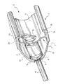
図1および2に示されている本発明の実施の形態によるスポーク取付け用部材9は、図3の分解図によりよく示されているとおり、本質的に円柱形の本体12を有しており、本体12は、本体12の第1の端部13において座孔11の周囲に当接すべく、前述のとおり座孔11よりも大きい最大横寸法D4を有している。
The spoke attachment member 9 according to the embodiment of the invention shown in FIGS. 1 and 2 has an essentially
スポーク取付け用部材9の本体12において、軸方向の孔14が第1の端部13から延びている。
In the
軸方向の孔14には、その長さの第1の部分にわたって延びる雌ねじ15が設けられ、スポーク8の端部81に設けられた雄ねじと適合する(図2を参照)。
The
スポーク取付け用部材9の本体12は、反対側の端部すなわち第2の端部16に、作業用工具との係合のため、六角孔の着座部17を有している。六角孔の着座部17の最大の横寸法D5が、六角孔付きの頭部を有するねじに使用される種類の工具、すなわちアレンレンチの先端の寸法に一致することは、すぐに理解できるであろう。
The
したがって、本発明によってリム1の上部ブリッジ5に形成されたアクセス開口10が、すでに述べたように、スポーク取付け用部材9の最大横寸法D4よりもわずかにだけ大きい横寸法D3を有しており、このような寸法が、スポーク取付け用部材9のスポーク取付け室7内への挿入を可能にするために充分であるばかりでなく、そのような作業用工具の挿入を可能にするためにも充分であることが、理解できるであろう。
Accordingly, the access opening 10 formed in the
そうでない場合、スポーク取付け用部材9の外表面は、従来技術のスポーク取付け用部材の場合と同様、ボックス・レンチまたはソケット・レンチ形式の作業用工具を係合させるために六角形形状とされなければならず、そのようなボックス・レンチを外側からスポーク取付け用部材に係合させるべく挿入することができるよう、アクセス開口10が、スポーク取付け用部材9の最大横寸法D4よりもはるかに大きい横寸法を有することになるであろう。
Otherwise, the outer surface of the spoke attachment member 9 must be hexagonal to engage a box wrench or socket wrench type work tool as in the case of prior art spoke attachment members. The
六角孔の着座部17の代案として、正方形孔の着座部、または任意の数の面を有する多面体孔の着座部を設けてもよい。
As an alternative to the hexagonal
さらに、スポーク取付け用部材9は、本体12の軸方向における中間部、すなわち具体的には、軸方向の孔14のねじ部15と六角孔の着座部17が形成されている部位との間の部位に、逃げ溝による環状の着座部18を有している。
Further, the spoke attachment member 9 is an intermediate portion of the
例えばNBRゴムまたはシリコンゴムあるいはナイロンで作られた塑性変形可能なリング19を、スポーク取付け用部材9の逃げ溝による環状の着座部18に挿入することができる。
For example, a plastically
最後に、リムへと当接するための座金(brass)20が、スポーク取付け用部材9とリム1との間に位置して両者の間の摩擦を低減するよう、スポーク取付け用部材9の本体12の第1の端部13に取り外し可能に組み合わされる。
Finally, a
好ましくは、この当接のための座金20は、通常は車輪の幾何学的な半径の方向から逸れた方向であるスポーク8の意図された組み立て方向に従ってスポーク取付け用部材9を容易に配向させることができるよう、孔付き球状キャプの形状とされている。
Preferably, the
スポーク取付け用部材9によるスポーク8のリムへ1の取付けは、以下のように行なわれる。
The attachment of 1 to the rim of the
所望に応じ、塑性変形可能リング19を、スポーク取付け用部材9の逃げ溝による環状の着座部18に挿入する。スポーク8の端部を、リム1の半径方向内側から(換言すれば、図2の下方から)座孔11へと挿入する。次いで、所望に応じて当接のための座金20を介装しつつ、スポーク取付け用部材9をスポーク8に整列させる。続いて、アレンレンチの先端をスポーク取付け用部材9の六角孔の着座部17に挿入し、トルクを加えてスポーク8のねじ端81をスポーク取付け用部材9の雌ねじ部15にねじ込む。
If desired, the plastically
スポーク8は、反対側の端部において車輪のハブへと前もって取付けておくことができ、あるいは最初の仮のねじ込みの後にハブへと取付けることができる。
The
スポーク取付け用部材9の雌ねじ部15へとスポーク8のねじ端81をねじ込むことにより、取付け用部材9の本体12がリム1へと当接し、スポーク8が車輪のリム1とハブとの間で引っ張られる。
By screwing the
スポーク8が、雌ねじ15が設けられてなる軸方向の孔部14へと完全にねじ込まれたとき、さらなるねじ込み動作によって、塑性変形可能リング19への入り込みおよびねじ込みが生じる。スポーク8の雄ねじが塑性変形可能リング19へと入り込むことにより、取付け用部材9によるより強力な固定が実現可能になり、自転車の使用時の振動によるスポーク8の緩みが防止される。
When the
この点で、塑性変形可能リング19は、スポークを組み付ける前は、内面が平滑であることが好ましい。しかしながら、塑性変形可能リング19に、スポーク取付け用部材9の本体12の雌ねじ15と同一かつ隣接する雌ねじを設けることも可能であり、いずれにせよ、スポーク8の組み付けによって塑性変形可能リング19にそのようなねじが存在することになる。
In this regard, the plastically
さらに、本発明によれば、塑性変形可能リング19の配置がスポーク取付け用部材9の中間部に位置するため、リング19がスポーク取付け用部材9の本体12の端部近傍に収容されている場合に生じうるリング19のスポーク取付け用部材9からの脱落の恐れなく、必要な推力を軸方向に加えることができるため、スポーク8による塑性変形可能リング19への自動的なねじ生成が容易になる。
Furthermore, according to the present invention, since the plastic
さらに、塑性変形可能リング19がスポーク取付け用部材9の中間位置に収容されていることを考えると、塑性変形可能リング19が、大気中の物質に対してよりよく保護されている。
Furthermore, considering that the plastically
今述べた塑性変形可能リング19がねじ15に隣接する逃げ溝による環状の着座部18に収容されている実施の形態によるスポーク取付け用部材9においては、バレル形式の接続の場合に生じるように、スポーク8が完全にねじ込まれた場合にのみ、すなわちスポーク8のねじ端81の長さがスポーク取付け用部材9のねじ15および逃げ溝による環状の着座部18の長さに等しい場合にのみ、その機能が完全に発揮され、スポーク8の張力の調節は、車輪のハブに位置する反対側の端部で行なわれる。しかしながら、ニップル形式の接続を実現したい場合には、スポーク8の塑性変形可能リング19との係合区域が、張力調整値によって決まり、スポーク8のスポーク取付け用部材9へのねじ込み深さが浅くなった場合には、係合長さが小さすぎる可能性があり、ゼロになる可能性さえある。
In the spoke attachment member 9 according to the embodiment in which the plastically
図4には、本発明によるスポーク取付け用部材20の実施の形態が示されており、塑性変形可能リング19のための逃げ溝による環状の着座部18が、本体12に、軸方向の孔14のねじ15に沿った中間位置において形成されており、したがってねじ15が、第1の部位15aおよび第2の部位15bによって定められている。
FIG. 4 shows an embodiment of a
この実施の形態においては、塑性変形可能リング19の作用がスポーク8のスポーク取付け用部材20へのねじ込み深さに依存せず、したがってスポーク8の張力に依存しないため、塑性変形可能リング19がとくに効果的である。したがって、このようなスポーク取付け用部材20は、ニップル形式の接続を実現するためにとくに適している。
In this embodiment, since the action of the plastically
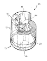
図5および6は、本発明の第3の実施の形態によるスポーク取付け用部材30を、それぞれ斜視図および断面斜視図で示している。このスポーク取付け用部材30は、作業用工具の係合のための着座部が、本体12の第2の端部16の表面外周に沿った凹所31a、31b、31c、31dの整列配置からなる点で、第1の実施の形態によるスポーク取付け用部材9と異なっている。さらに、第3の実施の形態によるスポーク取付け用部材30においては、軸方向の貫通孔14が、雌ねじ15を有する軸方向の行き止まりの非貫通孔14aに置き換えられている。
5 and 6 show a
この実施の形態によるスポーク取付け用部材30は、後続の図8のものと類似する十字形状の先端を有する工具によって操作することができる。
The
図7は、本発明の第4の実施の形態によるスポーク取付け用部材40の斜視図を示しており、工具との係合のための着座部を形成する凹所41a、41b、41c、41dが円形であって、全体が本体12の第2の端部16の面に形成されている点で、第3の実施の形態によるスポーク取付け用部材30と相違している。
FIG. 7 shows a perspective view of a
この実施の形態によるスポーク取付け用部材40は、図8に部分的に示されている円柱形の突起102a、102b、102c、および102dを備えた十字形状の先端101を有する工具100によって操作することができる。
The
図9は、本発明の第5の実施の形態によるスポーク取付け用部材50の斜視図を示しており、軸方向の孔14が貫通孔であり、工具との係合手段は、本体12の第2の端部16の環状の表面に形成された1組の直径に沿った切り欠き51a、51bで構成されている。
FIG. 9 shows a perspective view of a
この実施の形態によるスポーク取付け用部材50は、平たい先端部または十字形状の先端部を有するねじ回しによって操作することができる。塑性変形可能リング19が、本体12の軸方向の中間位置に配置されているおかげで、ねじ回しによって塑性変形可能リング19に損傷を与えることがないことに注目すべきである。
The
図10は、本発明の第6の実施の形態によるスポーク取付け用部材60を示しており、スポークの端部を受け入れるための軸方向の孔が行き止まりの非貫通孔であり(図10では見ることができない)、平たい先端部を有するねじ回しとの係合のための着座部が、本体12の第2の端部16の面上の直径に沿った切り欠き61で構成されている。
FIG. 10 shows a
図11は、本発明の第7の実施の形態によるスポーク取付け用部材70を示しており、第6の実施の形態のスポーク取付け用部材60と類似しているが、十字形状の先端部を有するねじ回しと係合すべく、本体12の第2の端部16の面上に直径に沿った1組の切り欠き71a、71bが形成されている。
FIG. 11 shows a
図12は、本発明の第8の実施の形態によるスポーク取付け用部材80を示しており、スポークの端部を受け入れるための軸方向の孔が行き止まりであり(図12では見ることができない)、本体12の第2の端部16の面上に、突き出した六角形の突起82が設けられている。
FIG. 12 shows a
この実施の形態によるスポーク取付け用部材は、ボックス・レンチまたはソケット・レンチといった工具で操作することができ、スポーク取付け用部材の本体12の全体の側面に六角形構成を形成する場合に必要になるボックス・レンチに比べ、はるかに寸法の小さいボックス・レンチまたはソケット・レンチで作業することができる。あるいは、突起82が正方形の断面、または任意の数の面を有する多角形の断面を有していてもよい。
The spoke attachment member according to this embodiment can be operated with a tool such as a box wrench or a socket wrench, and is required when forming a hexagonal configuration on the entire side of the
本発明の技術的範囲内のさらに別の実施の形態は、先端に対応する凹所が整列配置されている作業用工具とともに使用するため、スポーク取付け用部材の本体12の第2の端部16の面に、突起を周辺に整列配置して有している。例えば、図7のスポーク取付け用部材40の構成と、対応する図8の作業用工具100の構成とを、逆にすることができる。スポーク取付け用部材に、凹所による着座部に代えて突き出している突起を設けると、従来技術のものよりも小さい、好都合に小型な通常の工具を使用することができるため、好都合でありうる。
Yet another embodiment within the scope of the present invention is the
本発明によるスポーク取付け用部材のすべての実施の形態において、作業用工具の先端がスポーク取付け用部材の第2の端部16に係合したとき、作業用工具の先端がスポーク取付け用部材の本体12から横方向にはみ出すことがない点に注目すべきである。すなわち換言すると、すべての実施の形態において、リム1の上部ブリッジ5のアクセス開口の横方向の寸法D3は、スポーク取付け用部材の本体12の側面または工具係合面以外の側面の部位によって定められるスポーク取付け用部材の最大の横寸法D4よりも、わずかに大きいだけでよい。
In all embodiments of the spoke attachment member according to the present invention, when the tip of the work tool is engaged with the
最後に、図13は、本発明の第9の実施の形態によるスポーク取付け用部材90を、部分切断の斜視図で示している。
Finally, FIG. 13 shows a
この実施の形態によるスポーク取付け用部材90は、軸方向の孔14bが円形ではなく雌ねじも設けられていないという点で、第1の実施の形態によるスポーク取付け用部材9と相違している。一方で、軸方向の孔14bは、例えば図示されているような矩形など、スポークの張り出し頭部(図示されていない)に合致する形状の断面を有している。軸方向の孔14bのスポーク取付け用部材90の第2の端部16の側には、スポークの張り出し頭部に合致する形状の着座部14cが、軸方向の孔14bを切り欠いて設けられている。すなわち、軸方向の孔14bは、張り出し頭部が設けられてなるスポークの端部を、バレル形式の接続を実現するよう差込み係合させるべく構成されている。
The
さらに、張り出し頭部が設けられたスポークの端部を差込み係合させるためのこのような軸方向の孔14bで、図3〜12に示した他の実施の形態のスポーク取付け用部材の雌ねじ15付きの孔14を置き換え可能であることは、明らかであろう。
Furthermore, the
本発明のスポーク取付け用部材が、張り出し頭部が設けられてなるスポークの端部を差込み係合させるためのこのような軸方向の孔14bを有している場合、通常はスポークの組み付けが、何よりもまず最初にリムの側で、続いてハブの側で行なわれ、スポークのねじ端および雌ねじ付きの座孔が、ハブまたは第2のスポーク取付け用部材に設けられることを理解すべきである。さらに、このような場合においては、バレル形式の取付け用部材とスポークとが、スポークの張り出し頭部を取付け用部材の着座部、例えば着座部14cに係合させることによって回転に関して一体にされているため、適切な作業用工具によってバレル形式の取付け用部材にトルクを加えさえすれば、スポークをハブ側に位置するねじ付き座孔に対して回転させることができ、したがってスポークの張力の調節を行なうことができる。
When the spoke attachment member of the present invention has such an
あくまでも例として寸法を示すならば、スポークのねじ端における寸法は、鋼製のスポークの場合は2〜3mmの間であり、一方、アルミニウム製のスポークの場合には4〜6mmの間である。 By way of example only, the dimensions at the thread ends of the spokes are between 2 and 3 mm for steel spokes, and between 4 and 6 mm for aluminum spokes.
スポーク取付け用部材を、自転車の車輪のリム、とくにスポーク取付け室とタイヤ連結溝の間に上部仕切りブリッジを有するリムにおいて使用するものとして図示および説明したが、より幅広い用途があることは理解すべきである。実際、本発明のスポーク取付け用部材は、単溝の自転車用リムにおいても同様に使用することができ、あるいはハブにおける固定のために使用することも可能である。 Although the spoke attachment members have been shown and described for use in bicycle wheel rims, particularly rims having an upper partition bridge between the spoke attachment chamber and the tire connecting groove, it should be understood that there is a wider application. It is. In fact, the spoke attachment member of the present invention can be used in a single groove bicycle rim as well, or can be used for fixation in a hub.
自転車の車輪のスポークは、事実上半径方向に延びることができ、そのような場合、ハブ側の端部が通常、ハブの前面に形成された着座部に収容される頭部を有する一方で、リム側の端部が雄ねじを有している。あるいは、ハブから半径方向に広がったフランジにスポークを取付けることもでき、したがって、スポークがハブへと正接するように(tangentially)取付けられて半径方向から逸れた方向をとることができる。本発明のスポーク取付け用部材は、ハブから半径方向に広がる前記フランジの1つにハブへと正接するように組み付ける場合にとくに適している。 The spokes of the bicycle wheel can extend in a radial direction, in which case the hub side end usually has a head that is received in a seat formed in the front of the hub, The end on the rim side has a male thread. Alternatively, the spokes can be attached to flanges that extend radially from the hub, and therefore the spokes can be tangentially attached to the hub and take a direction away from the radial direction. The spoke attachment member of the present invention is particularly suitable when assembled to one of the flanges extending radially from the hub so as to be tangent to the hub.
さらに、図4に示したようにスポーク取付け用部材のねじに沿った中間位置に塑性変形可能リング19を配置すること、さらに一般的にいえば、例えば図3のスポーク取付け用部材9のように、スポーク取付け用部材の本体12の軸方向の中間位置に塑性変形可能リング19を配置することが、そのような配置が前述のとおり大きな利点をもたらすこと、および、ねじ15を有する軸方向の孔14または14aが軸部を通って延びている軸棒形式の取付け用部材(図示はされていない)においても機能できることに鑑み、それだけで進歩的特徴を構成していることを理解すべきである。そのような軸棒形式の取付け用部材の場合において、この進歩的特徴だけでも好都合な利点であることを考えると、頭部の外面は、従来技術に知られているとおり六角形であってもよく、正方形であってもよく、ボックス・レンチ形式の作業用工具と係合するための他の形状であってもよい。
Further, as shown in FIG. 4, a plastically
5 上部ブリッジ
6 タイヤ連結溝
7 スポーク取付室
8 スポーク
9 スポーク取付用部材
10 アクセス開口
11 座孔
12 スポーク取付用部材本体
13 スポーク取付用部材本体の第1端部
14 孔
14a 非貫通孔
14b 孔
14c スポーク頭部に合致する形状の着座部
15 ねじ
15a ねじの第1部位
15b ねじの第2部位
16 スポーク取付用部材本体の第2端部
17 六角孔の着座部
18 環状の着座部
19 リング
20 スポーク取付用部材
30 スポーク取付用部材
31a〜d 凹所
40 スポーク取付用部材
41a〜d 凹所
50 スポーク取付用部材
51a〜b 切り欠き
60 スポーク取付用部材
61 切り欠き
70 スポーク取付用部材
71a〜b 切り欠き
80 スポーク取付用部材
81 スポーク端部
82 突起
90 スポーク取付用部材
D3 アクセス開口の寸法
D4 スポーク取付用部材の最大横寸法
5 Upper bridge
6 Tire connecting
DESCRIPTION OF
20
31a-
60
Claims (37)
第1の端部(13)にて座孔(11)の周囲に当接するよう、座孔(11)の横寸法よりも大きい横寸法(D4)を有している本体(12)、
前記本体(12)の第1の端部(13)から延びるとともに、スポーク(8)と係合するための手段(15、15a、15b、14c)を備えている軸方向の孔(14、14a、14b)、および
前記第1の端部(13)と反対側にある前記本体(12)の第2の端部(16)に表面工具係合手段(17、31a〜d、41a〜d、51a〜b、61、71a〜b、82)を有しており、
前記本体(12)の最大の横寸法(D4)は、前記本体(12)の工具係合面以外の側面部によって定められることを特徴とするスポーク取付け用部材(9、20、30、40、50、60、70、80、90)。 In the member (9, 20, 30, 40, 50, 60, 70, 80, 90) for attaching the spoke (8) to the seat hole (11) in the wheel of the bicycle,
A body (12) having a lateral dimension (D4) greater than the lateral dimension of the seat hole (11) so as to abut the periphery of the seat hole (11) at the first end (13);
An axial hole (14, 14a) extending from the first end (13) of the body (12) and provided with means (15, 15a, 15b, 14c) for engaging with the spoke (8). 14b), and surface tool engagement means (17, 31a-d, 41a-d, 41a-d,) on the second end (16) of the body (12) on the opposite side of the first end (13). 51a-b, 61, 71a-b, 82),
The maximum lateral dimension (D4) of the main body (12) is determined by a side surface portion other than the tool engaging surface of the main body (12), characterized in that the spoke attachment member (9, 20, 30, 40, 50, 60, 70, 80, 90).
90)。 3. The tool engagement means (17, 31a-d, 41a-d, 51a-b, 61, 71a-b, 82) according to claim 1 or 2, wherein the axial hole (14 , 14a, 14b), and spoke attachment members (9, 20, 30, 40, 50, 60, 70, 80,
90).
形状をしていることを特徴とするスポーク取付け用部材(90)。 12. The axial hole (14b) according to any one of claims 1 to 11, wherein the axial hole (14b) has an undercut region (14c) for inserting and engaging the protruding head of the spoke (8). A spoke attachment member (90) characterized in that:
半径方向内側に位置する円周状のスポーク取付け室(7)、および
半径方向外側に位置する円周状のタイヤ連結溝(6)
を有し、
前記室(7)と前記溝(6)とが上部ブリッジ(5)によって分離されており、
前記室(7)が、それぞれのスポーク取付け用部材(9、20、30、40、50、60、70、80、90)によってスポーク(8)の第1の端部(81)をそれぞれ固定するための複数の座孔(11)を有しており、
前記上部ブリッジ(5)が、前記座孔(11)の1つにそれぞれ位置する複数のアクセス開口(10)を有しており、
前記アクセス開口(10)の横寸法(D3)が、スポーク取付け用部材(9、20、30、40、50、60、70、80、90)の本体(12)の最大の横寸法(D4)よりもわずかに大きいことを特徴とするリム(1)。 Bicycle wheel rim (19, 20, 30, 40, 50, 60, 70, 80, 90) in cooperation with a plurality of spoke attachment members (9, 20, 30, 40, 50, 60, 70, 80, 90) according to any one of the preceding claims. In 1)
Circumferential spoke attachment chamber (7) located radially inward, and circumferential tire connection groove (6) located radially outward
Have
The chamber (7) and the groove (6) are separated by an upper bridge (5);
The chamber (7) fixes the first end (81) of the spoke (8) by means of a respective spoke attachment member (9, 20, 30, 40, 50, 60, 70, 80, 90). A plurality of seat holes (11) for
The upper bridge (5) has a plurality of access openings (10) each located in one of the seat holes (11);
The lateral dimension (D3) of the access opening (10) is the largest lateral dimension (D4) of the body (12) of the spoke attachment member (9, 20, 30, 40, 50, 60, 70, 80, 90). Rim (1) characterized in that it is slightly larger than.
前記複数本のスポーク(8)のそれぞれの第1の端部(81)を取り付けるために
座孔(11)が設けられているリム(1)、
前記複数本のスポーク(8)のそれぞれの第2の端部を取り付けるために座孔が設けられている中央のハブ、および
それぞれが前記リム(1)の座孔(11)および前記ハブの座孔から選択された1つの座孔に位置する請求項1から23までの何れか一項に記載の複数のスポーク取付け用部材(9、20、30、40、50、60、70、80、90)
を有する自転車の車輪。 Multiple spokes (8),
A rim (1) provided with a seat hole (11) for attaching a first end (81) of each of the plurality of spokes (8);
A central hub provided with a seat hole for attaching the second end of each of the plurality of spokes (8), and a seat hole (11) of the rim (1) and a seat of the hub, respectively. 24. A plurality of spoke attachment members (9, 20, 30, 40, 50, 60, 70, 80, 90) located in one seat hole selected from the holes. )
Bicycle wheel with
前記本体(12)の少なくとも一部を座孔(11)に保持するための当接面(13)、
自身の長さの少なくとも一部にわたって延びている雌ねじ(15、15a、15b)
形状を有する軸方向の孔(14、14a)、
前記軸方向の孔(14、14a)内に位置する逃げ溝による環状の着座部(18)、および
前記環状の着座部(18)に収容され、かつ前記軸方向の孔(14、14a)と同軸な孔を有している塑性変形可能な環状部材(19)
が設けられており、
前記逃げ溝による環状の着座部(18)が、本体(12)の軸方向における中間位置に位置していることを特徴とするスポーク取付け用部材(9、20、30、40、50、60、70、80)。 In the member (9, 20, 30, 40, 50, 60, 70, 80) for attaching the screw end of the spoke (8) to the seat hole (11) in the bicycle wheel, the body (12)
A contact surface (13) for holding at least a part of the body (12) in the seat hole (11);
Internal thread (15, 15a, 15b) extending over at least part of its length
An axial hole (14, 14a) having a shape,
An annular seat (18) by a relief groove located in the axial hole (14, 14a), and the axial hole (14, 14a) received in the annular seat (18); Plastically deformable annular member (19) having a coaxial hole
Is provided,
A spoke attachment member (9, 20, 30, 40, 50, 60, characterized in that the annular seating portion (18) by the escape groove is located at an intermediate position in the axial direction of the main body (12). 70, 80).
Applications Claiming Priority (1)
| Application Number | Priority Date | Filing Date | Title |
|---|---|---|---|
| EP04425047A EP1559582B1 (en) | 2004-01-27 | 2004-01-27 | Attachment system for the spokes of a bicycle wheel |
Publications (1)
| Publication Number | Publication Date |
|---|---|
| JP2005212773A true JP2005212773A (en) | 2005-08-11 |
Family
ID=34639510
Family Applications (1)
| Application Number | Title | Priority Date | Filing Date |
|---|---|---|---|
| JP2005018761A Pending JP2005212773A (en) | 2004-01-27 | 2005-01-26 | Mounting system for bicycle wheel spoke |
Country Status (7)
| Country | Link |
|---|---|
| US (2) | US7137671B2 (en) |
| EP (1) | EP1559582B1 (en) |
| JP (1) | JP2005212773A (en) |
| CN (1) | CN100423957C (en) |
| AT (1) | ATE390294T1 (en) |
| DE (1) | DE602004012703D1 (en) |
| TW (1) | TW200538312A (en) |
Cited By (3)
| Publication number | Priority date | Publication date | Assignee | Title |
|---|---|---|---|---|
| JP2020524111A (en) * | 2017-06-19 | 2020-08-13 | アルピナ・ラッジ・エスピーエー | Nipple for spoke wheels especially for motorcycles |
| KR102342311B1 (en) * | 2021-03-29 | 2021-12-22 | 장혁주 | Nipple assembly for spoked wheel and spoked wheel including the same |
| JP2023551387A (en) * | 2020-11-10 | 2023-12-08 | アルピナ・ラッジ・エスピーエー | Self-locking nipples for spokes of spoked wheels and method of manufacturing such nipples |
Families Citing this family (27)
| Publication number | Priority date | Publication date | Assignee | Title |
|---|---|---|---|---|
| EP1559583B1 (en) * | 2004-01-27 | 2009-06-17 | Campagnolo S.R.L. | Spoke for a bicycle wheel, wheel and method for manufacturing such a spoke |
| US7490406B2 (en) * | 2005-05-04 | 2009-02-17 | William Shook | Bicycle wheel rim with internally reinforced spoke seats and method for producing them |
| ES2278520B1 (en) * | 2005-09-16 | 2008-07-01 | Bycmo Models, S.L. | WHEEL WITH RADIOS. |
| ITMI20072232A1 (en) * | 2007-11-26 | 2009-05-27 | Campagnolo Srl | RIM FOR BICYCLE WHEEL AND BICYCLE WHEEL INCLUDING SUCH RIM |
| EP2113978B1 (en) * | 2008-04-30 | 2012-06-06 | ABB Technology Ltd | A protective casing for a high voltage cable |
| TWI379779B (en) * | 2008-12-04 | 2012-12-21 | Tzusing Tho | Rim for racing bike |
| DE102009056739A1 (en) * | 2009-12-04 | 2011-06-09 | Dt Swiss Ag | Wheel for a powered by muscle vehicle and in particular for a bicycle |
| IT1395394B1 (en) * | 2009-09-07 | 2012-09-14 | Alpina Raggi Spa | RADIUS FOR WHEELS |
| ITPD20100004A1 (en) | 2010-01-18 | 2011-07-19 | Alpina Raggi Spa | NIPPLO PERFECTED |
| US20120013171A1 (en) * | 2010-07-17 | 2012-01-19 | Wen Hsuan Chen | Spoke Nipple with an Anti-shock Structure and its Manufacturing Method |
| IT1405763B1 (en) * | 2011-02-22 | 2014-01-24 | Alpina Raggi Spa | METHOD FOR THE REALIZATION OF SELF-LOCKING NIPPLES AND NIPPLES REALIZED ACCORDING TO THIS METHOD |
| US8967731B2 (en) | 2011-02-23 | 2015-03-03 | Shimano Inc. | Spoke attachment structure |
| TWM415823U (en) * | 2011-03-16 | 2011-11-11 | Kunshan Henry Metal Tech Co | Spoke tightening lock structure |
| US9651138B2 (en) | 2011-09-30 | 2017-05-16 | Mtd Products Inc. | Speed control assembly for a self-propelled walk-behind lawn mower |
| US20130300186A1 (en) * | 2011-11-04 | 2013-11-14 | Raphael Schlanger | Vehicle wheel spoke connection |
| TW201328901A (en) * | 2012-01-04 | 2013-07-16 | Kunshan Henry Metal Tech Co | Structure of rim and spoke set thereof |
| US9561685B2 (en) | 2012-02-09 | 2017-02-07 | Shimano, Inc. | Force-distributing apparatus for a bicycle wheel spoke |
| US9114844B2 (en) | 2012-10-03 | 2015-08-25 | Hauler Cycles, LLC | Bicycle conversion kit and tricycle apparatus |
| CN103847425B (en) * | 2012-12-07 | 2015-12-30 | 捷安特(昆山)有限公司 | The connection structure of wheel flower-drum and steel wire |
| DE102013002968A1 (en) * | 2013-02-22 | 2014-08-28 | Dt Swiss Ag | Impeller for at least partially muscle-powered vehicles and in particular bicycles |
| CN104044398A (en) * | 2013-03-14 | 2014-09-17 | 捷安特(昆山)有限公司 | Improved structure for connecting wheel hub and steel wires |
| CN108725087A (en) * | 2017-04-18 | 2018-11-02 | 德安百世实业股份有限公司 | Carbon fiber rim spoke |
| US20210155033A1 (en) * | 2019-11-22 | 2021-05-27 | Ruotemilano S.R.L. | Spoked wheel structure |
| IT202000018223A1 (en) | 2020-07-28 | 2022-01-28 | Campagnolo Srl | PROCEDURE AIMED AT THE CREATION OF A SPOKED WHEEL FOR A BICYCLE AND RELATIVE WHEEL |
| IT202000018217A1 (en) * | 2020-07-28 | 2022-01-28 | Campagnolo Srl | SPOKE ATTACHMENT ASSEMBLY FOR A BICYCLE SPOKED WHEEL, RELATIVE WHEEL AND PROCEDURE FOR THE CREATION OF THIS WHEEL |
| DE102021125543B4 (en) * | 2021-10-01 | 2023-05-25 | Dt Swiss Ag | Impeller component for an impeller of a two-wheeler and impeller operated at least partially with muscle power |
| IT202300000603A1 (en) | 2023-01-17 | 2024-07-17 | Alpina Raggi Spa | SELF-LOCKING NIPPLE FOR SPOKED WHEEL SPOKES |
Citations (18)
| Publication number | Priority date | Publication date | Assignee | Title |
|---|---|---|---|---|
| JPS5669502U (en) * | 1980-08-15 | 1981-06-09 | ||
| JPS581361Y2 (en) * | 1978-08-23 | 1983-01-11 | 株式会社高砂製作所 | wheel spoke nipples |
| JPS5993901U (en) * | 1982-12-16 | 1984-06-26 | 星工業株式会社 | vehicle nipples |
| JPS6043401U (en) * | 1983-08-29 | 1985-03-27 | 金井 宏之 | automotive wheels |
| JPS6084301U (en) * | 1983-11-10 | 1985-06-11 | 本田技研工業株式会社 | Spoke nipples for wheels with wire spokes |
| JPS6181801A (en) * | 1984-08-31 | 1986-04-25 | Honda Motor Co Ltd | How to assemble wire spokes and wheels for vehicles |
| JPH01226401A (en) * | 1988-03-07 | 1989-09-11 | Suzuki Motor Co Ltd | Spoke wheel for motor cycle |
| JPH03113201U (en) * | 1990-03-06 | 1991-11-19 | ||
| JPH0423501U (en) * | 1990-06-21 | 1992-02-26 | ||
| JPH04104001U (en) * | 1991-02-15 | 1992-09-08 | スズキ株式会社 | Spoke wheels for tubeless tires |
| JPH0712517B2 (en) * | 1990-08-09 | 1995-02-15 | 株式会社月星製作所 | Method for manufacturing nipples for wheels |
| JPH10244801A (en) * | 1996-10-24 | 1998-09-14 | Alpina Raggi Spa | Spoke nipple and manufacture therefor |
| US6036279A (en) * | 1997-03-28 | 2000-03-14 | Campagnolo S.R.L. | Spoke for a bicycle wheel and wheel including this spoke |
| DE10002527A1 (en) * | 2000-01-21 | 2001-07-26 | Dt Swiss Ag Biel | Spoke and spoke nipple system esp. for bicycle wheels have overlapping threaded section when screwed together, with one thread area applying higher clamp force |
| JP2001213101A (en) * | 2000-02-02 | 2001-08-07 | Shimano Inc | Spoke nipple for bicycle wheel |
| JP2001270301A (en) * | 2000-03-03 | 2001-10-02 | Campagnolo Spa | Rim for wheel of spoke type bicycle, particularly rim for wheel of tubeless tire, and wheel including the rim |
| US6497042B1 (en) * | 1998-07-29 | 2002-12-24 | Rolf Dietrich | Method of making a tensioned spoked bicycle wheel |
| JP2004161266A (en) * | 2002-11-08 | 2004-06-10 | Campagnolo Spa | Spoked wheel for bicycle, method for manufacturing the same, and parts kit therefor |
Family Cites Families (19)
| Publication number | Priority date | Publication date | Assignee | Title |
|---|---|---|---|---|
| BE513555A (en) * | 1944-01-21 | |||
| FR997154A (en) * | 1948-10-13 | 1952-01-02 | Dunlop Rubber Co | Advanced bicycle rim |
| US2778690A (en) * | 1953-05-15 | 1957-01-22 | Jr Anthony J Horling | Spoke nipple for bicycle wheel |
| US3909067A (en) * | 1974-03-08 | 1975-09-30 | Daryl L Nichols | Lightweight spoke construction |
| FR2616384B1 (en) * | 1987-06-10 | 1990-08-31 | Marcellier Robert | SPOKED WHEEL, PARTICULARLY FOR BICYCLES, MOPEDS, MOPEDS, MOTOR VEHICLES AND OTHERS |
| US5370486A (en) * | 1991-12-19 | 1994-12-06 | Plummer; Mark J. | Vehicle locking fastener assembly |
| FR2750913B1 (en) * | 1996-07-12 | 1998-10-09 | Mavic Sa | METHOD OF DRILLING A SPOKED RIM, RIM DRILLED ACCORDING TO THE METHOD, INSERT SUITABLE FOR EQUIPMENT ON THE RIM, AND WHEEL IN PARTICULAR FOR A CYCLE |
| FR2767285B1 (en) | 1997-08-13 | 1999-10-15 | Mavic Sa | RADIUS FOR CYCLE WHEEL, CYCLE WHEEL AND MANUFACTURING METHODS |
| ITTO980101A1 (en) | 1998-02-10 | 1999-08-10 | Campagnolo Srl | RACK FOR REAR BICYCLE WHEEL, SPOKED |
| US5904461A (en) * | 1998-05-07 | 1999-05-18 | Mckarge, Jr.; Gerald G. | Locking T-nut |
| US6846047B2 (en) | 2001-09-28 | 2005-01-25 | Rolf Dietrich | Tensioned spoked wheel assembly and spoke rim and nipple therefor |
| DE50002910D1 (en) * | 1999-04-09 | 2003-08-21 | Dt Swiss Ag Biel | SPOKE NIPPLE, ESPECIALLY FOR BICYCLES AND THE LIKE |
| FR2801248B1 (en) | 1999-11-18 | 2002-02-08 | Mavic Sa | DEVICE FOR HANGING THE END OF A RADIUS TO A RIM OR HUB |
| FR2810582B1 (en) | 2000-06-27 | 2002-10-11 | Mavic Sa | DEVICE FOR HANGING A RADIUS AT THE RIM OF A BICYCLE WHEEL |
| ITTO20010121A1 (en) | 2001-02-13 | 2002-08-13 | Campagnolo Srl | PROCEDURE FOR THE MANUFACTURE OF A BICYCLE WHEEL RIM, DEVICE FOR THE IMPLEMENTATION OF THE PROCEDURE, AND THE CIRCLE SO OBTAINED |
| CN1433762A (en) * | 2002-01-23 | 2003-08-06 | 李向荣 | New use of fluoroquinolone group medicine and berberine |
| US6517169B1 (en) * | 2002-03-26 | 2003-02-11 | Mark Yu | Spoked wheel for a bicycle |
| CN2547534Y (en) * | 2002-05-15 | 2003-04-30 | 田镇平 | Spoke assembly structure of bicycle rim |
| US6776460B1 (en) * | 2003-08-15 | 2004-08-17 | Chun-Hsun Lo | Combination of spokes and rims for bicycles |
-
2004
- 2004-01-27 EP EP04425047A patent/EP1559582B1/en not_active Expired - Lifetime
- 2004-01-27 AT AT04425047T patent/ATE390294T1/en not_active IP Right Cessation
- 2004-01-27 DE DE602004012703T patent/DE602004012703D1/en not_active Expired - Lifetime
-
2005
- 2005-01-14 TW TW094101252A patent/TW200538312A/en unknown
- 2005-01-26 JP JP2005018761A patent/JP2005212773A/en active Pending
- 2005-01-27 CN CNB2005100058910A patent/CN100423957C/en not_active Expired - Fee Related
- 2005-01-27 US US11/044,855 patent/US7137671B2/en not_active Expired - Fee Related
-
2006
- 2006-11-20 US US11/602,044 patent/US20070063575A1/en not_active Abandoned
Patent Citations (18)
| Publication number | Priority date | Publication date | Assignee | Title |
|---|---|---|---|---|
| JPS581361Y2 (en) * | 1978-08-23 | 1983-01-11 | 株式会社高砂製作所 | wheel spoke nipples |
| JPS5669502U (en) * | 1980-08-15 | 1981-06-09 | ||
| JPS5993901U (en) * | 1982-12-16 | 1984-06-26 | 星工業株式会社 | vehicle nipples |
| JPS6043401U (en) * | 1983-08-29 | 1985-03-27 | 金井 宏之 | automotive wheels |
| JPS6084301U (en) * | 1983-11-10 | 1985-06-11 | 本田技研工業株式会社 | Spoke nipples for wheels with wire spokes |
| JPS6181801A (en) * | 1984-08-31 | 1986-04-25 | Honda Motor Co Ltd | How to assemble wire spokes and wheels for vehicles |
| JPH01226401A (en) * | 1988-03-07 | 1989-09-11 | Suzuki Motor Co Ltd | Spoke wheel for motor cycle |
| JPH03113201U (en) * | 1990-03-06 | 1991-11-19 | ||
| JPH0423501U (en) * | 1990-06-21 | 1992-02-26 | ||
| JPH0712517B2 (en) * | 1990-08-09 | 1995-02-15 | 株式会社月星製作所 | Method for manufacturing nipples for wheels |
| JPH04104001U (en) * | 1991-02-15 | 1992-09-08 | スズキ株式会社 | Spoke wheels for tubeless tires |
| JPH10244801A (en) * | 1996-10-24 | 1998-09-14 | Alpina Raggi Spa | Spoke nipple and manufacture therefor |
| US6036279A (en) * | 1997-03-28 | 2000-03-14 | Campagnolo S.R.L. | Spoke for a bicycle wheel and wheel including this spoke |
| US6497042B1 (en) * | 1998-07-29 | 2002-12-24 | Rolf Dietrich | Method of making a tensioned spoked bicycle wheel |
| DE10002527A1 (en) * | 2000-01-21 | 2001-07-26 | Dt Swiss Ag Biel | Spoke and spoke nipple system esp. for bicycle wheels have overlapping threaded section when screwed together, with one thread area applying higher clamp force |
| JP2001213101A (en) * | 2000-02-02 | 2001-08-07 | Shimano Inc | Spoke nipple for bicycle wheel |
| JP2001270301A (en) * | 2000-03-03 | 2001-10-02 | Campagnolo Spa | Rim for wheel of spoke type bicycle, particularly rim for wheel of tubeless tire, and wheel including the rim |
| JP2004161266A (en) * | 2002-11-08 | 2004-06-10 | Campagnolo Spa | Spoked wheel for bicycle, method for manufacturing the same, and parts kit therefor |
Cited By (6)
| Publication number | Priority date | Publication date | Assignee | Title |
|---|---|---|---|---|
| JP2020524111A (en) * | 2017-06-19 | 2020-08-13 | アルピナ・ラッジ・エスピーエー | Nipple for spoke wheels especially for motorcycles |
| JP7087008B2 (en) | 2017-06-19 | 2022-06-20 | アルピナ・ラッジ・エスピーエー | Nipple for spoke wheels, especially for motorcycles |
| JP2023551387A (en) * | 2020-11-10 | 2023-12-08 | アルピナ・ラッジ・エスピーエー | Self-locking nipples for spokes of spoked wheels and method of manufacturing such nipples |
| JP7805365B2 (en) | 2020-11-10 | 2026-01-23 | アルピナ・ラッジ・エスピーエー | Self-locking nipple for spokes of a spoked wheel and method for manufacturing such a nipple |
| KR102342311B1 (en) * | 2021-03-29 | 2021-12-22 | 장혁주 | Nipple assembly for spoked wheel and spoked wheel including the same |
| WO2022211160A1 (en) * | 2021-03-29 | 2022-10-06 | (주)대진인터내셔널 | Nipple assembly for spoke wheel, and spoke wheel including same |
Also Published As
| Publication number | Publication date |
|---|---|
| CN1647955A (en) | 2005-08-03 |
| DE602004012703D1 (en) | 2008-05-08 |
| TW200538312A (en) | 2005-12-01 |
| ATE390294T1 (en) | 2008-04-15 |
| EP1559582B1 (en) | 2008-03-26 |
| US20070063575A1 (en) | 2007-03-22 |
| US7137671B2 (en) | 2006-11-21 |
| EP1559582A1 (en) | 2005-08-03 |
| US20050161997A1 (en) | 2005-07-28 |
| CN100423957C (en) | 2008-10-08 |
Similar Documents
| Publication | Publication Date | Title |
|---|---|---|
| JP2005212773A (en) | Mounting system for bicycle wheel spoke | |
| US6409278B1 (en) | Spoke nipple for bicycle wheel | |
| US12228158B2 (en) | Stick fit fastener recess system | |
| US7748790B2 (en) | Rim and spoke connection on a spoked wheel for a bicycle | |
| EP0786360A2 (en) | Bicycle hub | |
| US6393939B1 (en) | Bicycle crank arm parts/assembly and assembly tools | |
| US10495131B2 (en) | Blind nut, a blind nut assembly and mounting structure thereof | |
| TWM577403U (en) | Bicycle crank assembly | |
| JP5643582B2 (en) | Threaded joint with threaded bolt and nut | |
| JP2005504231A (en) | Self-tapping insert, insert assembly, and insert mounting method | |
| TWI606938B (en) | Wheel for at least partially muscle-powered vehicles and in particular bicycles | |
| EP2612765A2 (en) | Rim assembly | |
| US20130043714A1 (en) | Vehicle wheel spoke connection | |
| EP1604838B1 (en) | Tubeless-Tire Wheel | |
| US7077480B2 (en) | Nuts for securing spokes to rims | |
| US6840139B2 (en) | Tapered installation tool | |
| CN110799350B (en) | Spoke nipple for spoke-type wheel, in particular for motorcycle | |
| US20030006643A1 (en) | Bicycle wheel with two-section spokes | |
| US7140696B1 (en) | Internal spoke nipple with variable spoke angles | |
| US12454040B2 (en) | Bottom bracket tool | |
| US12215730B2 (en) | Fastener assembly | |
| EP3748173B1 (en) | Fastening device made as a nut or a bolt provided with a plug | |
| JP7538545B2 (en) | Nut structure | |
| JP6598346B1 (en) | Security nut removal tool | |
| JP3147424U (en) | Compound nut |
Legal Events
| Date | Code | Title | Description |
|---|---|---|---|
| A621 | Written request for application examination |
Free format text: JAPANESE INTERMEDIATE CODE: A621 Effective date: 20071112 |
|
| A131 | Notification of reasons for refusal |
Free format text: JAPANESE INTERMEDIATE CODE: A131 Effective date: 20100622 |
|
| A02 | Decision of refusal |
Free format text: JAPANESE INTERMEDIATE CODE: A02 Effective date: 20101124 |