JP2005199395A - Rotary cutter device - Google Patents
Rotary cutter device Download PDFInfo
- Publication number
- JP2005199395A JP2005199395A JP2004009040A JP2004009040A JP2005199395A JP 2005199395 A JP2005199395 A JP 2005199395A JP 2004009040 A JP2004009040 A JP 2004009040A JP 2004009040 A JP2004009040 A JP 2004009040A JP 2005199395 A JP2005199395 A JP 2005199395A
- Authority
- JP
- Japan
- Prior art keywords
- cutter
- drum
- cutter drum
- negative pressure
- suction
- Prior art date
- Legal status (The legal status is an assumption and is not a legal conclusion. Google has not performed a legal analysis and makes no representation as to the accuracy of the status listed.)
- Pending
Links
Images


Landscapes
- Labeling Devices (AREA)
Abstract
Description
本発明はラベリングマシンや印刷機などに適用可能な回転カッタ装置に関し、より詳細にはシート状物を正確な長さで連続的に切断する回転カッタ装置に関するものである。
The present invention relates to a rotary cutter device applicable to a labeling machine, a printing machine, and the like, and more particularly to a rotary cutter device that continuously cuts a sheet-like material with an accurate length.
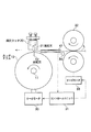
図11にラベリングマシンに配備された回転カッタ装置のモデル図を示す。
従来の回転カッタ装置は、支軸11を中心に一方向に回転するカッタドラム10と、カッタドラム10に対向配置した固定カッタ20とを具備している。
固定カッタ20の一側面には、カッタドラム10の周面と対向する固定刃21を突設している。
そして、供給ローラ32から等速で送られるシート状物(以下「ロールラベルL」という)は、両側に配置された一対のガイド板41で移送方向を誘導されながら前進し、カッタドラム10と固定カッタ20の間を通過する途中で、回転刃12が固定刃21の刃先を通過するときにロールラベルLを所定の長さに切断できるようになっている。
カッタドラム10はその外周面に突設した回転刃12と、カッタドラム10を駆動するサーボモータ30とを具備し、サーボモータ30はコントロールユニット31と電気的に接続している。
ロールラベルLを供給するための一対の回転ローラよりなる供給ローラ32も駆動源としてサーボモータ33を具備しいていて、コントロールユニット31と電気的に接続している。
そして、ロールラベルLの移送経路の途中には光電管34が配置してあって、ロールラベルLに表示されている切断間隔マークを読み取り、この情報をコントロールユニット31へ入力する。
コントロールユニット31はマシンの運転速度に対応してロールラベルLを所定の長さに切断できるように、カッタドラム10と供給ローラ32の各サーボモータ30,33の回転を制御するプログラムが組み込まれている。
FIG. 11 shows a model diagram of the rotary cutter device provided in the labeling machine.
The conventional rotating cutter device includes a
On one side surface of the fixed cutter 20, a fixed blade 21 that faces the peripheral surface of the
A sheet-like material (hereinafter referred to as “roll label L”) fed from the
The
A
A
The
前記した回転カッタ装置にはつぎのような改善すべき点がある。
(1)ロールラベルLを切断する瞬間、回転刃12が固定刃21の刃先に一致するため、ロールラベルLの先端の進行が一時的に停止させられる。
そのため、図示するようにロールラベルLがガイド板41間でジャミングを起こし易い。ロールラベルLのジャミングは、ロールラベルLの送り速度が速くなるほど起き易く、マシンの高速運転を進めるうえで大きな阻害要因の一つになっている。
回転カッタ装置を組み込んだラベリングマシンにおいては、ラベルのジャミング発生は絶対にあってはならず、その改善策の提案が切望されている。
(2)ロールラベルLがジャミングを起こさなくとも、切断時にロールラベルLの先端の進行が止められるために、ロールラベルLに弛みを生じる。
そのため、光電管34によるロールラベルLに表示されている切断間隔マークの読み取り精度が低下して、ラベルの切断位置に狂いが生じる。
(3)弛みを生じたロールラベルLを切断することになるため、回転刃12と固定刃21間における切れ味が悪く、またその切断面もきたない。
The rotary cutter device described above has the following points to be improved.
(1) Since the
Therefore, the roll label L easily causes jamming between the
In a labeling machine incorporating a rotary cutter device, label jamming should never occur, and a proposal for improvement is strongly desired.
(2) Even if the roll label L does not jam, the progress of the tip of the roll label L is stopped at the time of cutting, so that the roll label L is slackened.
Therefore, the reading accuracy of the cutting interval mark displayed on the roll label L by the
(3) Since the roll label L that has slackened is cut, the sharpness between the
本発明は以上の点に鑑みてなされたもので、その目的とするところは、高性能の回転カッタ装置を提供することにある。
さらに本発明はシート状物のジャミングの発生を回避して切断精度を向上できる、回転カッタ装置を提供することにある。
The present invention has been made in view of the above points, and an object thereof is to provide a high-performance rotary cutter device.
It is another object of the present invention to provide a rotary cutter device that can improve the cutting accuracy by avoiding jamming of a sheet-like material.
本発明は、支軸を中心に一方向に回転し、外周に回転刃を有するカッタドラムと、カッタドラムに対向配置した固定カッタとを具備した回転カッタ装置であって、前記カッタドラムの円周面であって、回転刃に対してドラムの回転方向側の周面に複数の孔を露出して形成し、前記カッタドラムの下部には、前記孔の他端の露出端の通過軌跡上に負圧溝と、排気溝とを直列的に形成した分配器を配置し、前記カッタドラムの周速度をシート状物の供給速度に対し相対的に大きくし、シート状物の切断直前から切断直後の区間に亘り、シート状物をカッタドラムの円周面に吸着して弛みをなくすように前記分配器の負圧溝を形成したことを特徴とする、回転カッタ装置を提供する。
より具体的には、支軸を中心に一方向に回転し、外周に回転刃を有するカッタドラムと、カッタドラムに対向配置した固定カッタとを具備した回転カッタ装置であって、前記カッタドラムの円周面であって、回転刃に対してドラムの回転方向側の周面に吸引孔を露出して形成すると共に、前記カッタドラムの円周面であって、前記吸引孔に対してドラムの回転方向側の周面に吸排孔を露出して形成し、
前記カッタドラムの下部には分配器を配置し、前記分配器には、前記吸引孔の他端の露出端の通過軌跡上に外負圧溝を形成すると共に、前記吸排孔の他端の露出端の通過軌跡上に内負圧溝と内排気溝とを直列的に形成し、前記カッタドラムの周速度をシート状物の供給速度に対し相対的に大きくし、シート状物の切断直前から切断直後の区間に亘り、シート状物をカッタドラムの円周面に吸着して弛みをなくすように前記分配器の内負圧溝を形成したことを特徴とする、回転カッタ装置を提供する。
また前記した何れかの回転カッタ装置において、前記カッタドラムから切断済みのシート状物を剥離して他のドラムへ受け渡す範囲に亘って形成した吸排溝または内吸排溝へエアを供給することを特徴とする、回転カッタ装置を提供する。
また前記した何れかの回転カッタ装置において、カッタドラムの周面に露出して形成する吸排孔をカッタドラムの回転方向に沿って複数形成したことを特徴とする、回転カッタ装置を提供する。
また前記した何れかの回転カッタ装置において、前記分配器に、吸引孔の他端の露出端の通過軌跡上に外負圧溝と、大気孔とを直列的に形成したことを特徴とする、回転カッタ装置を提供する。
The present invention is a rotary cutter device comprising: a cutter drum that rotates in one direction around a support shaft and has a rotary blade on the outer periphery; and a fixed cutter disposed opposite to the cutter drum, the circumference of the cutter drum A plurality of holes are exposed on the peripheral surface of the drum in the rotation direction with respect to the rotary blade, and the lower part of the cutter drum is on the trajectory of the exposed end of the other end of the hole. Distributor having a negative pressure groove and an exhaust groove formed in series is arranged, and the peripheral speed of the cutter drum is made relatively large with respect to the supply speed of the sheet material. The rotary cutter device is characterized in that the negative pressure grooves of the distributor are formed so as to eliminate looseness by adsorbing the sheet-like material to the circumferential surface of the cutter drum.
More specifically, there is provided a rotary cutter device comprising a cutter drum that rotates in one direction around a support shaft and has a rotary blade on the outer periphery, and a fixed cutter disposed opposite to the cutter drum, A suction hole is exposed and formed on a circumferential surface of the rotating blade side of the drum with respect to the rotary blade, and is a circumferential surface of the cutter drum, and is a circumferential surface of the drum with respect to the suction hole. Exposed and formed exhaust holes on the peripheral surface of the rotation direction,
A distributor is disposed below the cutter drum, and an outer negative pressure groove is formed on the path of the exposed end of the other end of the suction hole, and the other end of the suction / exhaust hole is exposed in the distributor. An inner negative pressure groove and an inner exhaust groove are formed in series on the end trajectory, and the peripheral speed of the cutter drum is increased relative to the supply speed of the sheet material, immediately before the cutting of the sheet material. The rotary cutter device is characterized in that an inner negative pressure groove of the distributor is formed so as to eliminate looseness by adsorbing the sheet-like material to the circumferential surface of the cutter drum over a section immediately after cutting.
Further, in any one of the rotary cutter devices described above, supplying air to the suction / exhaust grooves or the inner suction / discharge grooves formed over a range where the cut sheet-like material is peeled from the cutter drum and transferred to another drum. A rotating cutter device is provided.
Further, in any one of the above-described rotary cutter devices, a rotary cutter device is provided, in which a plurality of suction / exhaust holes formed on the peripheral surface of the cutter drum are formed along the rotation direction of the cutter drum.
Further, in any one of the above-described rotary cutter devices, the distributor is formed with an external negative pressure groove and an air hole in series on the passage trajectory of the exposed end of the other end of the suction hole. A rotary cutter device is provided.
本発明はつぎの少なくともひとつの特有の効果を奏する。
(1)シート状物を弛みのない状態に張った状態で切断できるので、ジャミングの発生を回避しつつ、切断効率がよく、かつ高精度に切断することができる。
(2)カッタドラムに簡単な改良を加えると共に、カッタドラムに分配器を配置するだけで、高性能の回転カッタ装置を得ることができる。
(3)カッタドラムに周面に吸着した切断済みのシート状物に、圧縮空気を吹付けて強制的に剥離するので、シート状物の受け渡しミスの発生を皆無にすることがでる。
The present invention has at least one of the following specific effects.
(1) Since the sheet-like material can be cut in a state in which it is not slackened, it is possible to cut with good cutting efficiency and high accuracy while avoiding the occurrence of jamming.
(2) A simple high-performance rotary cutter device can be obtained by simply adding a modification to the cutter drum and arranging a distributor on the cutter drum.
(3) Since compressed air is blown onto the cut sheet-like material adsorbed on the peripheral surface of the cutter drum, the sheet-like material is forcibly separated, so that no mistakes in the delivery of the sheet-like material can be eliminated.
以下図面を参照しながら本発明の実施の形態について説明する。
(1)回転カッタ装置の概要
図1に回転カッタ装置のモデル図を示す。
同図の右方には一対のローラで構成する供給ローラ40が位置すると共に、供給ローラ40の前方にロールラベルLを誘導するガイド板41が位置し、ガイド板41の左方に回転カッタ装置が位置する。
Embodiments of the present invention will be described below with reference to the drawings.
(1) Outline of Rotating Cutter Device FIG. 1 shows a model diagram of the rotating cutter device.
A supply roller 40 composed of a pair of rollers is located on the right side of the figure, and a
回転カッタ装置は、支軸11を中心に一方向に回転するカッタドラム10と、カッタドラム10に対向させて設置した固定カッタ50とにより構成する。
The rotary cutter device includes a
(2)カッタドラム
カッタドラム10は鉛直方向に配置した支軸11を中心に反時計回りに回転するドラムで、その外周面には鉛直方向に向けて回転刃12を突設している。
カッタドラム10の周面上であって、回転刃12に対してドラムの回転方向側の周面には、吸引孔13と、吸排孔14が形成されている。
カッタドラム10の周面上であって、回転刃12に対してドラム回転方向と逆方向側の周面には、逃げ溝15が形成されている。
逃げ溝15はカッタドラム10の隣に配設した移送ドラム70の外周面から突出した送り爪71との衝突を回避するための凹部である。
(2) Cutter Drum The
A
The
吸引孔13はラベルを吸着して搬送するための孔で、回転刃12に最も近い位置で、多段的に形成されている。
また吸排孔14はロールラベルLにラベルがちぎれない程度の張力を付与する機能と、切断後のラベルをドラム10の周面から強制的に剥離させる機能を併有する孔で、吸着して搬送吸引孔13に対して回転刃12から離隔する方向に沿って多段的に形成されている。本例では吸引孔13に対しドラム10の回転方向側に吸排孔14をずらして形成した場合を示す。
吸排孔14は図1に示すように多団的に一箇所だけ設けても機能するが、図2に示すようにカッタドラム10の周方向に沿って複数箇所に形成することが望ましい。
The
The suction /
The intake /
吸引孔13と各吸排孔14は、図4に示すように逆L字形を呈していて、各孔13,14の一端がカッタドラム10の周面に露出し、他端がカッタドラム10の底面に露出している。
本例では吸引孔13の他端の露出位置がカッタドラム10の周面に近く、吸排孔14の他端の露出位置が支軸11に近いその奥側に位置させた場合について示すが、その位置関係は図示した形態と逆であってもよい。
As shown in FIG. 4, the
In this example, the exposure position of the other end of the
カッタドラム10の下面には分配器60が回転しない状態で配置されている。
分配器60はカッタドラム10の外周面に露出した吸引孔13と各吸排孔14に所定の回転区間に亘ってエアの吸排をさせるためのもので、その上面には、図2に拡大して示すように、吸引孔13の他端の通過軌跡上に沿って円弧状の外負圧溝61と、大気孔62が直列的に形成されていると共に、吸排孔14の他端の通過軌跡上に沿って円弧状の内負圧溝63と円弧状の内排気溝64が直列的に形成されている。
The distributor 60 is arranged on the lower surface of the
The distributor 60 is for causing the
すなわち、支軸11を中心として分配器60の外方側に外負圧溝61と大気孔62とが形成され、その内方側に支軸11を中心として内負圧溝63と円弧状の内排気溝64とが形成されている。外負圧溝61と内負圧溝63は共に図示しない吸引ポンプと接続して常時吸引されるものであるのに対し、内排気溝64には常時エアが給気されている。
That is, an outer
外負圧溝61はラベルの移送範囲に亘って各吸引孔13に負圧を発生させるための溝であり、また大気孔62は大気に連通した孔で、ラベルを受け渡す際に吸引孔13を大気に開放して負圧を完全に切ることができる。
The outer
内負圧溝63はラベルの切断直前から切断時までの区間に亘って負圧を発生させるための溝で、その形成範囲は外負圧溝61より短く形成されている。
内排気溝64はカッタドラム10からラベルを剥離して他のドラムへ受け渡す範囲に亘ってエアを排出するための溝であって、その形成範囲は外負圧溝61の終端と大気孔62に跨って形成されている。
The inner
The
また図1に示すように、供給ローラ40によるロールラベルLの送り速度V1に対し、カッタドラム10の周速度V2が相対的に速くなるように、速度差を設けている。
ロールラベルLの送り速度V1に対し、カッタドラム10の周速度V2を相対的に速く設定したのは、ラベルを切断する直前にロールラベルLに適度の張力を与えて、ロールラベルLのジャミング発生を回避しながら、ラベルをきれいに切断するためである。
Further, as shown in FIG. 1, a speed difference is provided so that the peripheral speed V 2 of the
To feed speed V 1 of the roll label L, it was set peripheral speed V 2 of the
カッタドラム10の駆動源としては、高価なサーボモータやサーボ制御用プログラムを使用せずに、安価な汎用モータ35を使用する。
カッタドラム10の駆動源として汎用モータ35を使用できるのは、固定カッタ50を揺動させてカッタドラム10を回転させたまま、回転カッタ装置の運転を中断し得るように構成したためである。
As a drive source of the
The reason why the general-
(3)固定カッタ
本例では固定カッタ50の固定刃53を揺動可能に構成した場合について説明するが、固定カッタ50は固定刃53が揺動せずに固定式であってもよい。
本例で示す固定カッタ50は、支軸51を中心に揺動可能に枢支した揺動体52と、揺動体52の一側に突設した固定刃53と、揺動体52の時計回り方向へ向けた揺動を規制する揺動規制手段と、揺動体52に時計回り方向へ向けて常時付勢力を与える弾力体と、揺動体52に揺動力を強制的に与える揺動手段とを具備している。
(3) Fixed Cutter In this example, the case where the fixed
The fixed
[揺動体]
図5に揺動手段を除いた固定カッタ50の一例を示す。
全体形状が略コ字形を呈するフレーム54の上下板には、同一鉛直線上に軸受55,55が設けてあり、揺動体52の上下に突設した支軸51,51が軸受55,55に貫入して回転可能に枢支されている。
軸受55を用いずに、フレーム54に揺動体52の支軸51,51を直接枢支してもよい。また、固定刃53を設けた揺動体52の側面は平面でもよいが、固定刃53を隔てて供給ローラ40側の側面を斜めに面取りして形成しておくと、ロールラベルLの先端を刃先に円滑に案内できるといった利点がある。
[Oscillator]
FIG. 5 shows an example of the fixed
Instead of using the
[揺動規制手段]
揺動体52の側面と対向したフレーム54の一側面であって、支軸51に対して固定刃53に近い側には、揺動規制手段である調整ボルト56が貫通して取り付けてある。
調整ボルト56はその先端を揺動体52の側面に当接させることで揺動体52の時計回り方向の揺動を一定に規制するストッパ部材として機能するだけではなく、調整ボルト56の突出量を調整することで、揺動体52の取付角度、すなわち固定刃53の取付角度を調整する部材としても機能する。
[Oscillation restricting means]
On one side of the
The
[弾力体]
調整ボルト56を設けたフレーム54の同一の側面と揺動体52の間には、弾力体であるばね材57が収縮状態で介装されている。
ばね材57は揺動体52の枢支部のガタツキを吸収する機能と、揺動体52をガタツキのない状態で支持する機能と、固定刃53と回転刃12の刃先を調整するために揺動体52の揺動を許容する機能を併有する弾性部材で、揺動体52の側面を調整ボルト56に当接させる方向に常時ばね力が作用するように、支軸51を間に挟んで固定刃53の反対側に配設する。
すなわち、カッタドラム10に近い側から、調整ボル56、揺動体52の支軸部、ばね材57の順序の配列となる。
[Elastic body]
Between the same side surface of the
The
That is, from the side close to the
前記した揺動規制手段は図示した形態に限定されるものではなく、揺動規制手段はボルト以外の突出量を調整可能な公知の手段を適用できる。
また弾力体もコイルばね以外に各種の弾性部材を適用してもよく、また弾力体は縮設する形態だけでなく上記した付勢方向に引張力が発生するように張設する場合もある。
The above-described swing restricting means is not limited to the illustrated form, and any known means capable of adjusting the protruding amount other than the bolt can be applied to the swing restricting means.
Various elastic members other than the coil spring may be applied to the elastic body, and the elastic body may be stretched so as to generate a tensile force in the above-described biasing direction as well as being contracted.
[揺動手段]
図1に示すように揺動体52の固定刃32と反対側にはリンク部材58が延びていて、リンク部材58の端部が揺動手段59と連結している。
揺動手段59は固定刃52と一体の揺動体52を強制的に揺動させてロールラベルLの切断を中断させるためのもので、例えば通電により変位するソレノイド、各種の流体シリンダ、ねじ送り機構などを適用することができるが、構造が簡単で動作速度の速いエアシリンダが好適である。
[Oscillating means]
As shown in FIG. 1, a
The oscillating means 59 is for forcibly oscillating the
揺動手段59の作動は手動制御でもよいが、ラベリングマシンの運転停止、または運転の中断を電気的信号として感知したときに、この感知信号と連動して制御する自動制御であってもよい。この自動制御は特別複雑なプログラムは必要とせず、極めて簡単に制御することができる。
供給ローラ40の駆動源にはサーボモータを使用せず、歯車機構で十分に対応することが可能である。
The operation of the oscillating means 59 may be manual control, but may be automatic control that is controlled in conjunction with this sensing signal when the operation of the labeling machine is detected as an electrical signal. This automatic control does not require a special complicated program and can be controlled very easily.
A servo motor is not used as a drive source for the supply roller 40, and a gear mechanism can be used.
[固定刃の支持構造]
固定カッタ50は、図6に示すように固定刃53を有する揺動体52を三点で支持し得るように構成した。
ばね材57と揺動体52との接触部をP1、調整ボルト56と揺動体52との接触部をP2、揺動体52の支軸51の枢支部をP3としたとき、これらの三点で支持するようにした。固定刃53と一体の揺動体52をガタツキのない状態で枢支するためである。
[Support structure of fixed blade]
As shown in FIG. 6, the fixed
When the contact portion between the
支軸51を単に軸受で支持しただけでは、軸受に遊びがあるため、支軸51の揺動中心をまったく変位させないで枢支することは極めて困難であるが、ばね材57と調整ボルト56を組み合わせて使用することで、軸受の遊びに影響されずに揺動体52を一定位置に静止させることが可能となる。
支軸51を間に挟んでその前後に調整ボルト56とばね材57を配置した構成を採用することで、ばね材57と揺動体52との接触部P1が力点となり、調整ボルト56と揺動体52との接触部P2は支点となって、揺動体52の支軸51の枢支部P3を一方向に偏倚するため、枢支部P3の遊びは実質的になくなる。
したがって、揺動体52の揺動中心は、軸受のガタツキの大小に拘らず変位しない。
If the
Therefore, the rocking center of the rocking
(4)移送ドラム
移送ドラム70は鉛直軸を中心に回転するドラムで、外周面の一部に送り爪71が突設されている。
移送ドラム70の外周面には、カッタドラム10に接近する位置から移送位置までの範囲に亘って、湾曲ガイド72が対向して配置されている。
本例では移送ドラム70を非負圧吸引式ドラムで構成する場合について説明するが、ラベルの移送区間に亘って外周面に負圧を発生する公知の負圧吸引式ドラムで構成してもよい。
(4) Transfer Drum The
A
In this example, the case where the
(5)ラベルの切断方法
つぎにラベルの切断方法について説明する。
図1において、カッタドラム10はロールラベルLの送り速度V1より相対的に速い速度で回転している。
ロールラベルLの連続供給を開始すると、ロールラベルLはガイド板41を経て回転カッタ装置へ向けて移送され、カッタドラム10と固定カッタ50の間を通過していく。
カッタドラム10の回転刃12が固定カッタ50の固定刃53を通過する瞬間、所定の長さ寸法のラベルに切断する。
(5) Label cutting method Next, a label cutting method will be described.
In Figure 1, the
When the continuous supply of the roll label L is started, the roll label L is transferred to the rotary cutter device through the
As soon as the
図7〜図9に基づいてラベル切断時の詳細について説明する。
尚、図7〜図9においては、説明の便宜上、カッタドラム10の回転運動を直線運動として表記し、また分配器に形成した各溝61〜64も現実には円弧状であるが、直線的に表記して説明する。
Details at the time of label cutting will be described with reference to FIGS.
7 to 9, for convenience of explanation, the rotational motion of the
回転刃12が固定刃53に到達する直前に、吸排孔14の他端(下端)が分配器の内負圧溝63の右端に到達することで、吸排孔14に負圧が発生し、切断前のロールラベルLをカッタドラム10の外周面で吸着する。
同様に吸引孔13の他端(下端)が分配器の内負圧溝61の右端に到達することで、吸引孔13に負圧が発生して切断前のロールラベルLを吸着する。
カッタドラム10の周速度V2はロールラベルLの送り速度V1に対し相対的に速く設定してある。この速度差によりロールラベルLはカッタドラム10の外周面に吸着されたまま滑走しながら、引っ張られて弛みのない状態が維持される。
Immediately before the
Similarly, when the other end (lower end) of the
Circumferential speed V 2 of the
図8に示すように回転刃12が固定刃53に通過する際に、ロールラベルLはピンと張った状態で切断されることになる。
したがって、両刃12,53によるラベルの切れ味は従来と比べて格段によくなり、ラベルの切断面もきれいである。殊に弛みがなくなるので正確な位置でラベルを切断することが可能となる。
また、ラベルの切断時、ロールラベルLの先端の送りが一時的に停止するが、カッタドラム10の周速度V2がロールラベルLの送り速度V1に対し相対的に速く設定してあるため、この停止時間は極僅かとなって未切断のロールラベルLのジャミングの発生を回避できる。
As shown in FIG. 8, when the
Therefore, the sharpness of the label by the double-edged
Also, when cutting the labels, but feed the leading edge of the roll label L is temporarily stopped, since the circumferential velocity V 2 of the
切断されたラベルの先端部は、カッタドラム10の周面に吸着されることなく、カッタドラム10の周面に対向して配置した補助湾曲ガイド板73に誘導されながら移送ドラム70へ向けて進行した後、湾曲ガイド72に案内されて移送ドラム70の周面へ移行する。
切断されたラベルの後端部は、内負圧溝63を通過する吸排孔14と、外負圧溝61を通過する吸引孔13に吸着されて、カッタドラム10の周面を滑走することなく移送を続ける。
内負圧溝63を通過する吸排孔14と、外負圧溝61を通過する吸引孔13に吸着されたラベルは、カッタドラム10の周面を滑走することなく移送を続ける。
図9に示すように吸排孔14が内負圧溝63を通過して円弧状の内排気溝64に達すると同時に、吸引孔13が外負圧溝61を外れる。
その結果、内排気溝64から吸排孔14へエアが供給されて、ラベルをカッタドラム10の周面から強制的に剥離する。
またラベルの受け渡しの際、仮にラベルとドラムの周面との間が真空になっていたとしても、吸引孔13が大気孔62に至ると大気圧になってラベルの吸着力を完全に喪失するので、ラベルの受け渡しに失敗することがなくなる。
このようにして、カッタドラム10に残っていたラベルの後端部を図1に示す移送ドラム70へ受け渡しする工程が完了する。
The leading end portion of the cut label is not attracted to the peripheral surface of the
The rear end portion of the cut label is adsorbed by the suction /
The labels adsorbed by the suction / discharge holes 14 passing through the inner
As shown in FIG. 9, the
As a result, air is supplied from the
Further, even when the label is delivered, even if the space between the label and the peripheral surface of the drum is evacuated, when the
In this way, the process of transferring the rear end portion of the label remaining on the
(6)固定刃の取付角度の調整方法
固定カッタ50の固定刃53とカッタドラム10の回転刃12の刃先の微調整方法について説明する。
図6に示すカッタドラム10を手動でゆっくりと逆回転(矢印の反対方向)操作し、回転刃12が固定刃53位置の下流側から上流側(図の右方)へ向けて通過するとき、揺動体52が揺動するか否かを注視する。
回転刃53が固定刃12に当接し、揺動体52がばね材57を収縮させて支軸51の枢支部を中心に反時計回り方向に揺動すれば、固定刃12の刃先が所定の切断地点P4より回転刃12側へ入り込んでいることになる。
揺動体52の揺動量に応じて調整ボルト56を回転操作して、揺動体52の取付角度を微調整する。
そして、回転刃53を通過させたとき揺動体52の揺動が確認されなくなれば、その地点が、固定刃53の刃先が所定の切断地点P4に一致したことになる。
このように、カッタドラム10をゆっくりと回転操作して揺動体52の揺動の有無を確認するだけの作業で以って、固定刃53の取付角度を簡単かつ正確に調整することができる。
(6) Method for Adjusting Fixed Blade Mounting Angle A method for finely adjusting the fixed
When the
When the
The
Then, if no swing of the
As described above, the mounting angle of the fixed
(7)切断の中断
ロールラベルLの交換時などにおいては、回転カッタ装置による切断を一時的に中断する必要がある。
切断を中断するときは、ロールラベルLの供給を停止すると同時に、固定カッタ50を強制的に揺動させる。このときカッタドラム10の回転は継続させておく。
図10はこの中断時の回転カッタ装置を示すもので、固定カッタ50の揺動手段59が伸張方向に作動すると、リング部材58を介して固定刃53と一体の揺動体52が、ばね材57を圧縮変形しながら、支軸51を中心に反時計回り方向に揺動する。この揺動角θは5度〜9度程度で十分である。
揺動体52の揺動に伴い固定刃53と回転刃12との間に隙間を生じるため、カッタドラム10が回転していても切断は不能となる。
(7) Interruption of cutting When the roll label L is replaced, it is necessary to temporarily interrupt the cutting by the rotary cutter device.
When the cutting is interrupted, the supply of the roll label L is stopped, and at the same time, the fixed
FIG. 10 shows the rotating cutter device at the time of interruption. When the swinging means 59 of the fixed
A gap is formed between the fixed
10・・・カッタドラム
11・・・回転刃
13・・・吸引孔
14・・・吸排孔
40・・・供給ローラ
41・・・ガイド板
50・・・固定カッタ
51・・・支軸
52・・・揺動体
53・・・固定刃
54・・・フレーム
55・・・軸受
56・・・調整ボルト(揺動規制手段)
57・・・ばね材(弾力体)
58・・・リンク部材
59・・・揺動手段
60・・・分配器
61・・・外負圧溝
62・・・大気孔
63・・・内負圧溝
64・・・内排気溝
70・・・移送ドラム
71・・・送り爪
72・・・湾曲ガイド
73・・・補助湾曲ガイド
DESCRIPTION OF
57 ... Spring material (elastic body)
58 ...
Claims (5)
前記カッタドラムの円周面であって、回転刃に対してドラムの回転方向側の周面に複数の孔を露出して形成し、
前記カッタドラムの下部には、前記孔の他端の露出端の通過軌跡上に負圧溝と、排気溝とを直列的に形成した分配器を配置し、
前記カッタドラムの周速度をシート状物の供給速度に対し相対的に大きくし、
シート状物の切断直前から切断直後の区間に亘り、シート状物をカッタドラムの円周面に吸着して弛みをなくすように前記分配器の負圧溝を形成したことを特徴とする、
回転カッタ装置。 A rotary cutter device comprising a cutter drum that rotates in one direction around a support shaft and has a rotary blade on the outer periphery, and a fixed cutter arranged opposite to the cutter drum,
A circumferential surface of the cutter drum, wherein a plurality of holes are exposed and formed on a circumferential surface of the rotating direction of the drum with respect to the rotary blade;
A distributor having a negative pressure groove and an exhaust groove formed in series on the trajectory of the exposed end of the other end of the hole is disposed below the cutter drum,
Increasing the peripheral speed of the cutter drum relative to the sheet supply speed,
The negative pressure groove of the distributor is formed so as to eliminate the slack by adsorbing the sheet-like material to the circumferential surface of the cutter drum over a section immediately after cutting the sheet-like material,
Rotating cutter device.
前記カッタドラムの円周面であって、回転刃に対してドラムの回転方向側の周面に吸引孔を露出して形成すると共に、
前記カッタドラムの円周面であって、前記吸引孔に対してドラムの回転方向側の周面に吸排孔を露出して形成し、
前記カッタドラムの下部には分配器を配置し、
前記分配器には、前記吸引孔の他端の露出端の通過軌跡上に外負圧溝を形成すると共に、前記吸排孔の他端の露出端の通過軌跡上に内負圧溝と内排気溝とを直列的に形成し、
前記カッタドラムの周速度をシート状物の供給速度に対し相対的に大きくし、
シート状物の切断直前から切断直後の区間に亘り、シート状物をカッタドラムの円周面に吸着して弛みをなくすように前記分配器の内負圧溝を形成したことを特徴とする、
回転カッタ装置。 A rotary cutter device comprising a cutter drum that rotates in one direction around a support shaft and has a rotary blade on the outer periphery, and a fixed cutter arranged opposite to the cutter drum,
A circumferential surface of the cutter drum, and a suction hole is exposed and formed on the circumferential surface of the drum in the rotational direction with respect to the rotary blade;
A circumferential surface of the cutter drum, wherein the suction holes are exposed and formed on the circumferential surface of the drum in the rotation direction with respect to the suction holes;
A distributor is arranged at the bottom of the cutter drum,
In the distributor, an outer negative pressure groove is formed on the passage trajectory of the exposed end of the other end of the suction hole, and an inner negative pressure groove and an inner exhaust are formed on the passage trajectory of the exposed end of the other end of the suction / exhaust hole. Forming a groove in series,
Increasing the peripheral speed of the cutter drum relative to the sheet supply speed,
The inner negative pressure groove of the distributor is formed so as to eliminate the slack by adsorbing the sheet-like material to the circumferential surface of the cutter drum over a section immediately after cutting the sheet-like material,
Rotating cutter device.
Priority Applications (1)
| Application Number | Priority Date | Filing Date | Title |
|---|---|---|---|
| JP2004009040A JP2005199395A (en) | 2004-01-16 | 2004-01-16 | Rotary cutter device |
Applications Claiming Priority (1)
| Application Number | Priority Date | Filing Date | Title |
|---|---|---|---|
| JP2004009040A JP2005199395A (en) | 2004-01-16 | 2004-01-16 | Rotary cutter device |
Publications (2)
| Publication Number | Publication Date |
|---|---|
| JP2005199395A true JP2005199395A (en) | 2005-07-28 |
| JP2005199395A5 JP2005199395A5 (en) | 2006-04-20 |
Family
ID=34822193
Family Applications (1)
| Application Number | Title | Priority Date | Filing Date |
|---|---|---|---|
| JP2004009040A Pending JP2005199395A (en) | 2004-01-16 | 2004-01-16 | Rotary cutter device |
Country Status (1)
| Country | Link |
|---|---|
| JP (1) | JP2005199395A (en) |
Cited By (13)
| Publication number | Priority date | Publication date | Assignee | Title |
|---|---|---|---|---|
| JP2007253321A (en) * | 2006-03-22 | 2007-10-04 | Hunkeler Ag | Transverse cutting device and method of operating the horizontal cutting device |
| JP2007260875A (en) * | 2006-03-29 | 2007-10-11 | Kao Corp | Sheet cutting method and device therefor |
| JP2007260794A (en) * | 2006-03-27 | 2007-10-11 | Koyo Autom Mach Co Ltd | Rotary cutter device |
| CN101822591A (en) * | 2009-10-19 | 2010-09-08 | 尤妮佳股份有限公司 | The manufacture method of the complex of the serialgram of absorbent commodity and manufacturing installation |
| JP2012055251A (en) * | 2010-09-10 | 2012-03-22 | Tsukioka:Kk | Device for manufacturing small sheet piece |
| CN102673829A (en) * | 2012-05-22 | 2012-09-19 | 许嘉斌 | Three-dimensional packer for square object |
| CN103057741A (en) * | 2013-01-25 | 2013-04-24 | 宁夏松久自动化设备有限公司 | Household paper packaging die device |
| CN103057765A (en) * | 2013-01-25 | 2013-04-24 | 宁夏松久自动化设备有限公司 | Packaging film cutting device |
| JP5563691B1 (en) * | 2013-03-29 | 2014-07-30 | 株式会社豊岡製作所 | Web cutting device |
| JP2014198632A (en) * | 2014-06-12 | 2014-10-23 | 株式会社豊岡製作所 | Web cutting apparatus |
| CN111230998A (en) * | 2020-02-28 | 2020-06-05 | 江苏新美星包装机械股份有限公司 | Vacuum adsorption device on cutting drum in label cutting machine |
| CN113858286A (en) * | 2021-09-03 | 2021-12-31 | 安徽中伟包装有限公司 | Fixed distance negative pressure adsorption type slitting device for production of self-sealing bags |
| CN117163740A (en) * | 2023-10-26 | 2023-12-05 | 临猗县源泰热能有限公司 | Paper grade (stock) rewinding machine with dust removal function |
-
2004
- 2004-01-16 JP JP2004009040A patent/JP2005199395A/en active Pending
Cited By (22)
| Publication number | Priority date | Publication date | Assignee | Title |
|---|---|---|---|---|
| JP2007253321A (en) * | 2006-03-22 | 2007-10-04 | Hunkeler Ag | Transverse cutting device and method of operating the horizontal cutting device |
| JP2007260794A (en) * | 2006-03-27 | 2007-10-11 | Koyo Autom Mach Co Ltd | Rotary cutter device |
| JP2007260875A (en) * | 2006-03-29 | 2007-10-11 | Kao Corp | Sheet cutting method and device therefor |
| JP4726674B2 (en) * | 2006-03-29 | 2011-07-20 | 花王株式会社 | Sheet cutting method and apparatus |
| CN101822591B (en) * | 2009-10-19 | 2013-10-09 | 尤妮佳股份有限公司 | Method and apparatus for manufacturing composite body of continuous sheet of absorbent article |
| CN101822591A (en) * | 2009-10-19 | 2010-09-08 | 尤妮佳股份有限公司 | The manufacture method of the complex of the serialgram of absorbent commodity and manufacturing installation |
| JP2011083547A (en) * | 2009-10-19 | 2011-04-28 | Unicharm Corp | Method and device for manufacturing composite of continuous sheets for absorptive article |
| WO2011048954A1 (en) * | 2009-10-19 | 2011-04-28 | ユニ・チャーム株式会社 | Method and device for manufacturing composite of continuous sheets for absorptive article |
| JP2012055251A (en) * | 2010-09-10 | 2012-03-22 | Tsukioka:Kk | Device for manufacturing small sheet piece |
| CN102673829B (en) * | 2012-05-22 | 2015-04-15 | 许嘉斌 | Three-dimensional packer for square object |
| CN102673829A (en) * | 2012-05-22 | 2012-09-19 | 许嘉斌 | Three-dimensional packer for square object |
| CN103057765A (en) * | 2013-01-25 | 2013-04-24 | 宁夏松久自动化设备有限公司 | Packaging film cutting device |
| CN103057741A (en) * | 2013-01-25 | 2013-04-24 | 宁夏松久自动化设备有限公司 | Household paper packaging die device |
| JP5563691B1 (en) * | 2013-03-29 | 2014-07-30 | 株式会社豊岡製作所 | Web cutting device |
| JP2014198623A (en) * | 2013-03-29 | 2014-10-23 | 株式会社豊岡製作所 | Web cutting apparatus |
| JP2014198632A (en) * | 2014-06-12 | 2014-10-23 | 株式会社豊岡製作所 | Web cutting apparatus |
| CN111230998A (en) * | 2020-02-28 | 2020-06-05 | 江苏新美星包装机械股份有限公司 | Vacuum adsorption device on cutting drum in label cutting machine |
| CN111230998B (en) * | 2020-02-28 | 2024-06-07 | 江苏新美星包装机械股份有限公司 | Vacuum adsorption device on cutting drum in label cutting machine |
| CN113858286A (en) * | 2021-09-03 | 2021-12-31 | 安徽中伟包装有限公司 | Fixed distance negative pressure adsorption type slitting device for production of self-sealing bags |
| CN113858286B (en) * | 2021-09-03 | 2022-12-20 | 安徽中伟包装有限公司 | Fixed distance negative pressure adsorption type slitting device for production of self-sealing bags |
| CN117163740A (en) * | 2023-10-26 | 2023-12-05 | 临猗县源泰热能有限公司 | Paper grade (stock) rewinding machine with dust removal function |
| CN117163740B (en) * | 2023-10-26 | 2024-01-16 | 临猗县源泰热能有限公司 | Paper grade (stock) rewinding machine with dust removal function |
Similar Documents
| Publication | Publication Date | Title |
|---|---|---|
| JP2005199395A (en) | Rotary cutter device | |
| EP1721850B1 (en) | Method and device for changing the web speed | |
| JP4587662B2 (en) | Cutter device and printer equipped with the same | |
| JP4227703B2 (en) | Punch unit for punching sheet material | |
| JP2008126325A (en) | Mechanism for positioning and carrying booklet in cutter | |
| JP4328199B2 (en) | Rotating cutter device and method for adjusting fixed blade mounting angle in rotating cutter device | |
| JP2002018773A (en) | Cutter device | |
| US7191690B2 (en) | Helical mechanism cutting unit and method for operating for the same | |
| JPH05124276A (en) | Printer | |
| JPH01308661A (en) | Paper cutting mechanism for printer | |
| EP0183982A1 (en) | Photographic paper accommodating apparatus | |
| KR100782672B1 (en) | How to adjust the mounting angle of fixed blade in rotary cutter device and rotary cutter device | |
| JP2007260794A (en) | Rotary cutter device | |
| JP5658393B1 (en) | Filling and packaging machine | |
| JPH06320481A (en) | Sheet material cutting device | |
| JP2000024996A (en) | Cutting equipment | |
| JP3072557B2 (en) | Perforation cutter device | |
| JP2553762Y2 (en) | Log guide device for slicer | |
| JPH08142429A (en) | Cutter of printer | |
| JP3451727B2 (en) | Sheet cutting equipment | |
| GB1262753A (en) | Web-cutting apparatus | |
| JPH01210296A (en) | Slitter device | |
| JP3157227B2 (en) | Sheet cutting equipment | |
| JPH09193087A (en) | Straight cut cutter | |
| JP2009172714A (en) | Cutting device for corrugated fin |
Legal Events
| Date | Code | Title | Description |
|---|---|---|---|
| A521 | Written amendment |
Effective date: 20060303 Free format text: JAPANESE INTERMEDIATE CODE: A523 |
|
| A621 | Written request for application examination |
Effective date: 20060303 Free format text: JAPANESE INTERMEDIATE CODE: A621 |
|
| A977 | Report on retrieval |
Free format text: JAPANESE INTERMEDIATE CODE: A971007 Effective date: 20080115 |
|
| A131 | Notification of reasons for refusal |
Free format text: JAPANESE INTERMEDIATE CODE: A131 Effective date: 20080129 |
|
| A521 | Written amendment |
Free format text: JAPANESE INTERMEDIATE CODE: A523 Effective date: 20080306 |
|
| A131 | Notification of reasons for refusal |
Free format text: JAPANESE INTERMEDIATE CODE: A131 Effective date: 20090512 |
|
| A02 | Decision of refusal |
Effective date: 20091013 Free format text: JAPANESE INTERMEDIATE CODE: A02 |