JP2005192612A - Glucose concentration measuring apparatus - Google Patents
Glucose concentration measuring apparatus Download PDFInfo
- Publication number
- JP2005192612A JP2005192612A JP2003435182A JP2003435182A JP2005192612A JP 2005192612 A JP2005192612 A JP 2005192612A JP 2003435182 A JP2003435182 A JP 2003435182A JP 2003435182 A JP2003435182 A JP 2003435182A JP 2005192612 A JP2005192612 A JP 2005192612A
- Authority
- JP
- Japan
- Prior art keywords
- light
- optical fiber
- living body
- glucose concentration
- irradiation
- Prior art date
- Legal status (The legal status is an assumption and is not a legal conclusion. Google has not performed a legal analysis and makes no representation as to the accuracy of the status listed.)
- Withdrawn
Links
Images


Landscapes
- Investigating Or Analysing Materials By Optical Means (AREA)
- Measurement Of The Respiration, Hearing Ability, Form, And Blood Characteristics Of Living Organisms (AREA)
Abstract
Description
この発明は、グルコース濃度測定装置に関するものである。 The present invention relates to a glucose concentration measuring apparatus.
従来、糖尿病の判断のために血中グルコース濃度測定が行われており、特に、糖尿病患者のインシュリン投与量を決定する血糖値を検査するために、グルコース濃度の測定が行われている。グルコース濃度の測定は、一般に、指や腕から採取した血液を直接分析することにより行われている。患者の体内における血液中のグルコース濃度は、食事の前後や運動後などの測定条件によって変化するため、正確な血糖値を得るためには、頻繁なグルコース濃度測定が必要である。
しかしながら、採血した血液を直接分析する上記方法は、グルコース濃度の測定の度に注射針等を刺して採血しなければならず、患者にかかる負担が大きいという問題がある。
Conventionally, blood glucose concentration measurement has been performed for the determination of diabetes, and in particular, glucose concentration measurement has been performed in order to examine blood glucose levels that determine the insulin dose of diabetic patients. The measurement of glucose concentration is generally performed by directly analyzing blood collected from a finger or an arm. Since the glucose concentration in the blood in the patient's body changes depending on the measurement conditions such as before and after meals and after exercise, frequent glucose concentration measurement is necessary to obtain an accurate blood glucose level.
However, the above-described method for directly analyzing the collected blood has a problem in that blood must be collected by inserting an injection needle or the like every time the glucose concentration is measured, and the burden on the patient is large.
この問題を解決するために、指、腕、耳朶などの生体組織に対し、外部から近赤外光を照射して生体内で拡散させ、生体外に出射された光を検出する非侵襲的なグルコース濃度測定方法が提案されている(例えば、特許文献1参照。)。この特許文献1の方法は、複数本の発光ファイバと複数本の受光ファイバとを束ねて構成した光ファイババンドルを用意し、該光ファイババンドルを構成する各光ファイバの先端面を生体表面に接触状態に配置する。そして、ハロゲンランプから複数の発光ファイバに集光した近赤外光をそれら発光ファイバの先端面から照射することにより、生体内に入射させ、生体内において拡散されて生体表面から生体外に戻る光を複数の受光ファイバにおいて受光するとともに、受光された光のスペクトルを分析することによりグルコースの濃度を算出するものである。
特許文献1に示される方法は、多数の発光ファイバおよび受光ファイバを使用して、照射光量および検出光量を増加させることで、検出されるグルコース濃度の情報量を増加させている。しかしながら、ハロゲンランプからの光を光ファイババンドルに集光させる場合に、ファイババンドル全体の断面積に対し、該ファイババンドルを構成する発光ファイバのコアの断面積の占める割合は非常に小さいため、ハロゲンランプから発せられた光の内、大部分は発光ファイバ内に入射されることなく捨てられてしまうという不都合がある。この不都合を回避するためには、ハロゲンランプの発光量を増大させる必要があるが、この場合には、装置が大型化したり発熱量が増大したりする問題が考えられる。
The method disclosed in
また、特許文献1に示される方法は、受光ファイバにより受光した光を回折格子ユニットにより分光し、分光された光を受光素子ユニット、すなわち、光検出器により検出しているが、受光ファイバの数が増えると光検出器に必要とされる受光面積が増大する。複数の受光ファイバにより受光されたすべての光をもれなく受光するためには、大型の光検出器が必要となる。光検出器はその寸法が大きくなると急激に値段が高くなるため、コストが高くつくという問題がある。
In the method disclosed in
また、特許文献1に示される装置では、光の照射量および受光量を大きく確保するために、発光ファイバおよび受光ファイバとしては、全て、200μmという比較的大きな同一のコア径の光ファイバを使用している。しかしながら、同じ発光ファイバから生体内に入射され同じ受光ファイバによって受光される光であっても、大きなコア径の光ファイバから発せられた光は様々な光路長の経路をたどることになる。このため、受光ファイバに受光される光には、様々な進達度の光の情報が含まれ、グルコース濃度の測定精度が低下してしまうという不都合がある。
Further, in the apparatus shown in
特に、生体内において拡散あるいは透過されて、体外に放出される光はごく微量であり、発光ファイバから受光ファイバまでの2つのファイバ間を光が伝播する間に、種々の生体組織によって散乱、吸収されるため、光量が大幅に減衰するという問題がある。このため、受光ファイバに受光される光からは、可能な限りノイズを除去しておく必要がある。 In particular, a very small amount of light diffused or transmitted in the living body and emitted outside the body is scattered and absorbed by various living tissues while the light propagates between the two fibers from the light emitting fiber to the light receiving fiber. Therefore, there is a problem that the amount of light is greatly attenuated. For this reason, it is necessary to remove noise from light received by the light receiving fiber as much as possible.
この発明は上述した事情に鑑みてなされたものであって、光源から発せられた光を効率よく生体に伝達し、S/N比を改善して測定精度を向上し得るグルコース濃度測定装置を提供することを目的とする。 The present invention has been made in view of the above-described circumstances, and provides a glucose concentration measuring apparatus that can efficiently transmit light emitted from a light source to a living body, improve the S / N ratio, and improve measurement accuracy. The purpose is to do.
上記目的を達成するために、本発明は、以下の手段を提供する。
本発明は、光源と、該光源から発せられた光を導光する単一の装置内光ファイバとを備える装置本体と、生体表面に接触状態に配置され、光源からの光を生体内に向けて照射する測定プローブと、これら装置本体と測定プローブとを着脱可能に接続する照射用光ファイバとを備え、該照射用光ファイバの一端面が測定プローブの先端面に固定され、他端面が装置内光ファイバの端面に突き当てられた状態で前記装置本体に取り付けられるグルコース濃度測定装置を提供する。
In order to achieve the above object, the present invention provides the following means.
The present invention relates to an apparatus main body comprising a light source and a single in-device optical fiber that guides light emitted from the light source, and arranged in contact with the surface of the living body, and directs the light from the light source into the living body. A measuring probe for irradiating the optical fiber, and an irradiating optical fiber for detachably connecting the apparatus main body and the measuring probe, one end surface of the irradiating optical fiber being fixed to the distal end surface of the measuring probe, and the other end surface being the apparatus Provided is a glucose concentration measuring device that is attached to the device main body while being abutted against an end face of an inner optical fiber.
この発明によれば、光源から発せられ、装置内光ファイバ内を導光されてきた光が、装置内光ファイバの端面から出射される。装置内光ファイバの端面には、照明用光ファイバがその端面を突き当てた状態で装置本体に取り付けられているので、装置内光ファイバの端面から出射された光は、照射用光ファイバ内に入射させられる。照射用光ファイバの他端面は測定プローブの先端面に固定されているので、測定プローブを生体の表面に密着させることにより、光源から発せられた光を効率よく生体内に入射させることが可能となる。すなわち、光源からの光を無駄なく生体内に入射させることにより、小さい光源で生体内へ入射させる光量を増大させることができ、光源の大型化や発熱の増加を抑えることができる。また、光源からの光を効率よく生体内に入射させるので、生体外部において受光される光に含まれる信号成分を増大させて測定精度を高めることが可能となる。
また、照明用光ファイバを装置本体から取り外すことにより、保守を容易に行うことが可能となる。
According to this invention, the light emitted from the light source and guided through the in-device optical fiber is emitted from the end face of the in-device optical fiber. Since the illumination optical fiber is attached to the end face of the optical fiber in the apparatus with the end face abutting on the end face, the light emitted from the end face of the in-apparatus optical fiber enters the irradiation optical fiber. Incident. Since the other end surface of the irradiation optical fiber is fixed to the distal end surface of the measurement probe, it is possible to make the light emitted from the light source efficiently enter the living body by bringing the measuring probe into close contact with the surface of the living body. Become. That is, by making the light from the light source enter the living body without waste, the amount of light incident on the living body with a small light source can be increased, and the increase in the size of the light source and the increase in heat generation can be suppressed. Moreover, since the light from the light source is efficiently incident on the living body, it is possible to increase the signal component included in the light received outside the living body and increase the measurement accuracy.
Further, the maintenance can be easily performed by removing the illumination optical fiber from the apparatus main body.
上記発明においては、装置内光ファイバが、照射用光ファイバのコア径以下のコア径を有することとしてもよい。
このようにすると、装置内光ファイバの端面が、該装置内光ファイバと同等またはそれより大きなコア径を有する照射用光ファイバの端面に突き合わせられ、装置内光ファイバ内を導光されてきた光は、漏れなくコア径の大きな照射用光ファイバ内に入射されるので、光の損失を低減して効率を高め、測定精度をさらに向上することが可能となる。
In the above invention, the in-device optical fiber may have a core diameter equal to or smaller than the core diameter of the irradiation optical fiber.
In this way, the end face of the in-device optical fiber is abutted against the end face of the irradiation optical fiber having a core diameter equal to or larger than that of the in-device optical fiber, and the light guided through the in-device optical fiber. Is incident on the irradiation optical fiber having a large core diameter without leakage, so that it is possible to reduce the loss of light, increase the efficiency, and further improve the measurement accuracy.
上記発明においては、装置内光ファイバおよび照射用光ファイバが、それぞれマルチモードファイバからなることとしてもよい。
この発明によれば、コア径の大きなマルチモードファイバを使用することにより、種々のモードを有する光を効率よく導光することができ、またコストも低減することができる。
In the above-described invention, the in-device optical fiber and the irradiation optical fiber may each be composed of a multimode fiber.
According to the present invention, by using a multimode fiber having a large core diameter, light having various modes can be guided efficiently, and the cost can be reduced.
また、本発明は、上記発明において、前記測定プローブが、前記照射用光ファイバの周囲に半径方向に所定間隔をあけて配置された複数の受光用光ファイバを備えるグルコース濃度測定装置を提供する。
この発明によれば、照射用光ファイバから出射された光が生体内に入射され、生体内において拡散ないし透過された後に、生体表面から外部に放出される光が、照射用光ファイバの周囲に配置されている受光用光ファイバによって受光される。小さい照射面積の照射用光ファイバから光を生体内に入射し、その入射点から周囲に広がるように進行する光が、その周囲に複数配置した受光用光ファイバで受光されるので、生体外に放出される光を漏れなく受光することが可能となる。特に、照射用光ファイバと受光用光ファイバとを所定の間隔をあけて配置したので、各受光用光ファイバには、生体内に入射された光のうち、一定の深さまで進達した光が多く受光されることになる。したがって、グルコースの情報を多く含む領域まで進達した光を受光することが可能となり、グルコース濃度の測定精度を高めることができる。
Moreover, the present invention provides the glucose concentration measuring apparatus according to the above invention, wherein the measurement probe includes a plurality of light receiving optical fibers arranged at predetermined intervals in the radial direction around the irradiation optical fiber.
According to the present invention, the light emitted from the irradiation optical fiber enters the living body, and after being diffused or transmitted in the living body, the light emitted to the outside from the living body surface is surrounded around the irradiation optical fiber. Light is received by the optical fiber for receiving light. Light enters the living body from the irradiation optical fiber having a small irradiation area, and the light that travels so as to spread from the incident point to the surroundings is received by a plurality of receiving optical fibers arranged around it. The emitted light can be received without leakage. In particular, since the irradiation optical fiber and the light receiving optical fiber are arranged at a predetermined interval, each of the light receiving optical fibers has a lot of light that has reached a certain depth among the light incident on the living body. Light will be received. Therefore, it is possible to receive light that has reached a region containing a lot of glucose information, and the measurement accuracy of the glucose concentration can be improved.
上記発明においては、各受光用光ファイバのコア径が、照射用光ファイバのコア径より大きいことが好ましい。
照射用光ファイバのコア径が大きい場合あるいは、照射用光ファイバがファイババンドルの形態で提供されている場合には、照射用光ファイバの端面の各位置から生体内に光が入射される。このため、同一の受光用光ファイバにより受光される光の中には、種々の光路長を有する光が含まれることになる。したがって、グルコース濃度の測定に必要な深さまで進達した光以外に、グルコース濃度の測定に不要な深さまで進達した光が比較的大きな強度を有して含まれることになり、検出信号におけるノイズ成分を増大させている。
In the said invention, it is preferable that the core diameter of each optical fiber for light reception is larger than the core diameter of the optical fiber for irradiation.
When the core diameter of the irradiation optical fiber is large, or when the irradiation optical fiber is provided in the form of a fiber bundle, light enters the living body from each position on the end face of the irradiation optical fiber. For this reason, light having various optical path lengths is included in the light received by the same light receiving optical fiber. Therefore, in addition to the light that has traveled to the depth necessary for measuring the glucose concentration, the light that has traveled to the depth unnecessary for the glucose concentration measurement is included with a relatively large intensity, and noise components in the detection signal are reduced. It is increasing.
これに対して、この発明によれば、同一の受光用光ファイバにより受光される光の光路長の幅を狭めることができる。特に、照射用光ファイバのコア径を十分に小さく設定することにより、生体内に実質的に一点から光を入射させることが可能となり、上記作用をさらに向上することができる。これにより、検出信号に含まれるノイズ成分を低減して測定精度を向上することができる。例えば、照射用光ファイバのコア径を50μmとし、受光用光ファイバのコア径を200μmとすれば効果的である。 On the other hand, according to the present invention, the width of the optical path length of the light received by the same light receiving optical fiber can be reduced. In particular, by setting the core diameter of the irradiating optical fiber sufficiently small, it becomes possible to make light enter the living body substantially from one point, and the above action can be further improved. Thereby, the noise component contained in a detection signal can be reduced and measurement accuracy can be improved. For example, it is effective if the core diameter of the irradiation optical fiber is 50 μm and the core diameter of the light receiving optical fiber is 200 μm.
さらに、上記発明においては、照射用光ファイバが、装置本体と測定プローブとの間で分岐されていることが好ましい。
これによれば、分岐された各照射用光ファイバから生体内に光が入射される。各照射用光ファイバの周囲には所定間隔をあけて複数の受光用光ファイバが配置されているので、生体表面の複数地点における測定が可能となる。その結果、一の照射用光ファイバからの光の入射を阻害する要因、例えば、体毛が存在している場合においても、他の照射用光ファイバからの光の入射および受光用光ファイバによる光の受光が正常に行われるので、測定の確実性を向上することができる。
Furthermore, in the said invention, it is preferable that the irradiation optical fiber is branched between the apparatus main body and the measurement probe.
According to this, light enters the living body from each branched optical fiber for irradiation. Since a plurality of light receiving optical fibers are arranged around each irradiation optical fiber at predetermined intervals, measurement at a plurality of points on the surface of the living body is possible. As a result, even if there is a factor that obstructs the incidence of light from one irradiation optical fiber, such as body hair, the incidence of light from another irradiation optical fiber and the light from the light receiving optical fiber Since light reception is performed normally, the reliability of measurement can be improved.
さらに、本発明は、生体に照射する光を発生する光源と、生体において拡散あるいは透過させられた光を検出する光検出器とを備える装置本体と、光源からの光を生体内に向けて出射する照射用光ファイバと、生体内からの光を受光して前記光検出器まで導光する複数の受光用光ファイバと、これら照射用光ファイバの端面および該照射用光ファイバの端面の周囲に半径方向に所定間隔をあけて配される受光用光ファイバの端面が配置された先端面を生体表面に接触させる測定プローブとを備え、各受光用光ファイバのコア径が、照射用光ファイバのコア径より大きいグルコース濃度測定装置を提供する。 Furthermore, the present invention provides an apparatus main body including a light source that generates light to irradiate a living body, a light detector that detects light diffused or transmitted in the living body, and emits light from the light source toward the living body. An optical fiber for irradiation, a plurality of optical fibers for receiving light from the living body and guiding the light to the photodetector, and an end face of the optical fiber for irradiation and a periphery of the end face of the optical fiber for irradiation A measuring probe that contacts the living body surface with a distal end surface on which the end surfaces of the light receiving optical fibers arranged at predetermined intervals in the radial direction are arranged, and the core diameter of each light receiving optical fiber is equal to that of the irradiation optical fiber A glucose concentration measuring device larger than the core diameter is provided.
この発明によれば、光源から発せられた光が装置本体から照射用光ファイバを介して生体内に入射され、生体内において拡散あるいは透過させられた光が受光用光ファイバによって受光されて装置本体内まで導光され、光検出器により検出される。照射用光ファイバおよび受光用光ファイバは測定プローブの先端面に、相互に所定の間隔をあけて配置されているので、照射用光ファイバから出射された光は、生体内を所定の深さまで進達した後に受光用光ファイバにより受光される。その結果、光ファイバの端面の間隔を調節しておくことにより、グルコース濃度に関する情報を多く含む光を受光することが可能となる。また、受光用光ファイバのコア径を照射用光ファイバのコア径より大きく設定しているので、受光用光ファイバに到達する光の光量を増加させることができる。したがって、検出信号に含まれるノイズ成分を低減して測定精度を向上することができる。 According to the present invention, light emitted from the light source is incident on the living body from the apparatus main body via the irradiation optical fiber, and light diffused or transmitted in the living body is received by the light receiving optical fiber, and the apparatus main body is received. The light is guided inward and detected by a photodetector. Since the irradiation optical fiber and the light receiving optical fiber are arranged at a predetermined distance from each other on the distal end surface of the measurement probe, the light emitted from the irradiation optical fiber advances to a predetermined depth in the living body. After that, the light is received by the light receiving optical fiber. As a result, by adjusting the distance between the end faces of the optical fibers, it is possible to receive light containing a lot of information on the glucose concentration. Further, since the core diameter of the light receiving optical fiber is set larger than the core diameter of the irradiation optical fiber, the amount of light reaching the light receiving optical fiber can be increased. Therefore, the noise component contained in the detection signal can be reduced and the measurement accuracy can be improved.
さらに、本発明は、生体に照射する光を発生する光源と、生体において拡散あるいは透過させられた光を検出する光検出器とを備える装置本体と、光源からの光を生体内に向けて出射する照射用光ファイバと、生体内からの光を受光して前記光検出器まで導光する受光用光ファイバと、これら照射用光ファイバの端面および受光用光ファイバの端面が配置された先端面を生体表面に接触させる測定プローブとを備え、照射用光ファイバが複数に分岐され、各照射用光ファイバの端面が、前記受光用光ファイバの端面の周囲に半径方向に所定間隔をあけて配置され、各受光用光ファイバのコア径が、照射用光ファイバのコア径より大きいグルコース濃度測定装置を提供する。 Furthermore, the present invention provides an apparatus main body including a light source that generates light to irradiate a living body, a light detector that detects light diffused or transmitted in the living body, and emits light from the light source toward the living body. Irradiating optical fiber, receiving optical fiber for receiving light from the living body and guiding it to the photodetector, and an end surface of the irradiating optical fiber and an end surface of the receiving optical fiber. A measurement probe for bringing the optical fiber into contact with the surface of the living body, the optical fiber for irradiation is branched into a plurality, and the end surfaces of the optical fibers for irradiation are arranged around the end surface of the optical fiber for light reception with a predetermined interval in the radial direction Thus, a glucose concentration measuring device is provided in which the core diameter of each light receiving optical fiber is larger than the core diameter of the irradiation optical fiber.
この発明によれば、複数に分岐された照射用光ファイバが、受光用光ファイバの周囲から生体内に光を入射させるので、これらの照射用光ファイバから発せられ生体内で拡散しあるいは透過した光は、中央の受光用光ファイバによって受光される。各照射用光ファイバの端面が、受光用光ファイバの端面の周囲に半径方向に所定間隔をあけて配置され、かつ、各受光用光ファイバのコア径が、照射用光ファイバのコア径より大きく設定されているので、受光用光ファイバに到達する光の光量を増大させ、グルコース濃度の測定に必要な進達度の光を多く含む信号を受光することにより、検出信号に含まれるノイズ成分を低減して測定精度を向上することができる。 According to the present invention, the irradiation optical fiber branched into a plurality makes the light enter the living body from the periphery of the light receiving optical fiber, and is emitted from these irradiation optical fibers and diffused or transmitted in the living body. The light is received by the central light receiving optical fiber. The end faces of the respective irradiation optical fibers are arranged at predetermined intervals in the radial direction around the end faces of the light receiving optical fibers, and the core diameters of the respective light receiving optical fibers are larger than the core diameters of the irradiation optical fibers. Because it is set, the amount of light reaching the optical fiber for receiving light is increased, and by receiving a signal containing a large amount of light necessary for measuring the glucose concentration, the noise component contained in the detection signal is reduced. Thus, the measurement accuracy can be improved.
さらに、本発明は、生体に照射する光を発生する光源と、生体において拡散あるいは透過させられた光を検出する光検出器とを備える装置本体と、光源からの光を生体内に向けて出射する照射用光ファイバと、生体内からの光を受光して前記光検出器まで導光する受光用光ファイバと、これら照射用光ファイバの端面および受光用光ファイバの端面が配置された先端面を生体表面に接触させる測定プローブとを備え、照射用光ファイバが複数に分岐され、各照射用光ファイバの端面の周囲に半径方向に所定間隔をあけて、複数の受光用光ファイバの端面が配置され、各受光用光ファイバのコア径が、照射用光ファイバのコア径より大きく設定され、各照射用光ファイバからみて、最も近い距離に配置されている受光用光ファイバまでの距離の2倍より離れた位置に、次に近い受光用光ファイバが配置されているグルコース濃度測定装置を提供する。 Furthermore, the present invention provides an apparatus main body including a light source that generates light to irradiate a living body, a light detector that detects light diffused or transmitted in the living body, and emits light from the light source toward the living body. Irradiating optical fiber, receiving optical fiber for receiving light from the living body and guiding it to the photodetector, and an end surface of the irradiating optical fiber and an end surface of the receiving optical fiber. A measuring probe that contacts the surface of the living body, the irradiation optical fiber is branched into a plurality of ends, and the end faces of the plurality of light receiving optical fibers are spaced at predetermined intervals in the radial direction around the end faces of the irradiation optical fibers. The core diameter of each optical fiber for receiving light is set larger than the core diameter of the optical fiber for irradiation, and the distance to the optical fiber for receiving light arranged closest to the irradiation optical fiber is set. To apart from the fold position, it provides a glucose concentration measuring apparatus next nearest receiving optical fiber is disposed.
この発明によれば、複数に分岐された照射用光ファイバから光が生体内に入射され、生体内において拡散あるいは透過した後に、照射用光ファイバの周囲に配置されている複数の受光用光ファイバにより受光される。各照射用光ファイバは受光用光ファイバよりも小さいコア径を有しているので、周囲の受光用光ファイバには生体内において一定の光路長を経た光が受光される。特に、各照射用光ファイバからみて、最も近い距離に配置されている受光用光ファイバには、最も短い光路長を経た光が受光されるので、その距離をグルコース濃度の測定に必要な進達度が得られる距離に設定しておくことにより、多くのグルコース濃度の情報を検出することが可能となる。 According to the present invention, a plurality of light receiving optical fibers arranged around the irradiation optical fiber after light is incident on the living body from the plurality of irradiation optical fibers branched and diffused or transmitted in the living body. Is received. Since each irradiation optical fiber has a smaller core diameter than the light receiving optical fiber, the surrounding light receiving optical fiber receives light having a certain optical path length in the living body. In particular, the light receiving optical fiber arranged at the shortest distance as viewed from each irradiation optical fiber receives the light having the shortest optical path length, and the distance is used to measure the progress required for measuring the glucose concentration. It is possible to detect a lot of information on the glucose concentration by setting the distance to obtain.
一方、各照射用光ファイバからみて次に近い受光用光ファイバまでの距離は、最も近い受光用光ファイバまでの距離の2倍より離れているので、当該次に近い受光用光ファイバに入射される光は、最も近い受光用光ファイバに入射される光と比較するとその光路長が2倍より大きくなる。光路長が大きくなればなるほど光は減衰し、特に、2倍より大きくなると、ほとんど無視し得るほどにまで減衰するという知見が得られた。この発明によれば、各受光用光ファイバには、当該受光用光ファイバに最も近い照射用光ファイバからの光が多く受光され、他の照射用光ファイバからの光は無視し得るほどに減衰される。したがって、照射用光ファイバを多数配置して、体毛等による光の入射の阻害を回避しつつ、他の照射用光ファイバからのグルコース濃度の測定に不必要な光が受光用光ファイバに受光されて、ノイズが増大することを回避することができる。 On the other hand, since the distance from each irradiation optical fiber to the next light receiving optical fiber is more than twice the distance to the nearest light receiving optical fiber, it is incident on the next light receiving optical fiber. Compared with the light incident on the nearest light receiving optical fiber, the optical path length of the light is greater than twice. It has been found that as the optical path length increases, the light attenuates, and in particular, when it exceeds 2 times, the light attenuates to an almost negligible level. According to the present invention, each light receiving optical fiber receives a large amount of light from the irradiation optical fiber closest to the light receiving optical fiber, and light from other irradiation optical fibers is negligibly attenuated. Is done. Therefore, by arranging a large number of irradiation optical fibers, light that is unnecessary for measuring the glucose concentration from other irradiation optical fibers is received by the light receiving optical fibers while avoiding obstruction of light incidence due to body hair or the like. Thus, an increase in noise can be avoided.
さらに、本発明は、生体に照射する光を発生する光源と、生体において拡散あるいは透過させられた光を検出する光検出器とを備える装置本体と、光源からの光を生体内に向けて出射する複数の照射用光ファイバと、生体内からの光を受光して前記光検出器まで導光する複数の受光用光ファイバと、これら照射用光ファイバの端面および受光用光ファイバの端面が規則的に配置された先端面を生体表面に接触させる測定プローブとを備え、各受光用光ファイバにおいて受光された光の検出信号に重み付けをして相互に加減算することにより、生体内を所定の深さまで進達した光の情報を抽出する情報抽出手段を備えるグルコース濃度測定装置を提供する。 Furthermore, the present invention provides an apparatus main body including a light source that generates light to irradiate a living body, a light detector that detects light diffused or transmitted in the living body, and emits light from the light source toward the living body. A plurality of irradiating optical fibers, a plurality of receiving optical fibers that receive light from the living body and guide the light to the photodetector, and an end face of the irradiating optical fiber and an end face of the receiving optical fiber are regular. A measuring probe for bringing the tip end surface disposed in contact with the surface of the living body, weighting the detection signals of the light received in each light receiving optical fiber, and adding and subtracting them to each other to obtain a predetermined depth in the living body. Provided is a glucose concentration measuring device provided with an information extracting means for extracting information of light that has been advanced.
この発明によれば、複数の照射用光ファイバから出射された光は生体内において拡散あるいは透過させられた後に複数の受光用光ファイバにより受光され光検出器において検出される。各照射用光ファイバおよび受光用光ファイバの端面は生体表面に接触させられる測定プローブの先端面に規則的に配列されているので、各受光用光ファイバに受光される光の中に、各照射用光ファイバからの光がどのような割合で含まれているのかが予め把握できる。そこで、情報抽出手段の作動により、各受光用光ファイバにおいて受光された光の検出信号に重み付けをして相互に加減算することにより、グルコース濃度の測定に必要な深さまで進達した光の成分情報を残し、他の成分を相殺してほぼゼロにすることができる。その結果、検出信号からノイズを除去して測定精度を向上することが可能となる。 According to this invention, the light emitted from the plurality of irradiation optical fibers is diffused or transmitted in the living body and then received by the plurality of light receiving optical fibers and detected by the photodetector. Since the end surfaces of each irradiation optical fiber and light receiving optical fiber are regularly arranged on the tip surface of the measurement probe that is brought into contact with the surface of the living body, each irradiation light fiber receives each irradiation in the light received by each light receiving optical fiber. It is possible to grasp in advance what proportion of light from the optical fiber is included. Therefore, by operating the information extraction means, the detection information of the light received in each light receiving optical fiber is weighted and added to or subtracted from each other, so that the component information of the light progressed to the depth necessary for measuring the glucose concentration is obtained. The remaining components can be offset to almost zero. As a result, noise can be removed from the detection signal to improve measurement accuracy.
上記発明においては、照射用光ファイバおよび受光用光ファイバの端面が、一定のピッチで2次元的に配列されていることが好ましい。
このようにすることで、上記加減算を簡易にすることが可能となり、ノイズの除去を容易に行うことができる。
In the said invention, it is preferable that the end surface of the optical fiber for irradiation and the optical fiber for light reception is arranged two-dimensionally with the fixed pitch.
By doing in this way, it becomes possible to simplify the said addition and subtraction, and noise can be removed easily.
さらに、上記発明においては、前記光源が、波長領域の異なる複数の広帯域光源と、これら広帯域光源から発せられた光を合波する合波手段とを備えることとしてもよい。
このようにすることで、各照射用光ファイバに光源からの光が効率よく供給され、高輝度の光を生体内に入射して、受光用光ファイバに受光される光量を増大させ、測定精度の向上を図ることが可能となる。
Furthermore, in the above invention, the light source may include a plurality of broadband light sources having different wavelength regions, and a multiplexing unit that combines the light emitted from these broadband light sources.
In this way, light from the light source is efficiently supplied to each irradiation optical fiber, and high-intensity light enters the living body, increasing the amount of light received by the light receiving optical fiber, and measuring accuracy. Can be improved.
本発明によれば、光源からの光が光ファイバによって漏れなく、効率よく生体表面まで導いて、生体内に入射することにより、測定精度の向上を図ることができる。また、光源を小型化できるので、装置の大型化や発熱増大を防止してコンパクトに製造することができるという効果を奏する。 According to the present invention, the light from the light source can be efficiently guided to the surface of the living body without leaking through the optical fiber and incident on the living body, thereby improving the measurement accuracy. In addition, since the light source can be reduced in size, there is an effect that the apparatus can be manufactured in a compact manner while preventing an increase in size of the apparatus and an increase in heat generation.
以下、本発明の一実施形態に係るグルコース濃度測定装置について図面を参照して説明する。
本実施形態に係るグルコース濃度測定装置1は、図1に示されるように、生体Aに照射する光を発生する光源2と、該光源2から出射された光を分光する分光器3とを有する光照射部4と、生体A内で拡散あるいは透過した光を生体A外部において検出する光検出部5と、該光検出部5により検出された光のスペクトルに基づいて生体A内のグルコース濃度を算出する演算部6とを備えている。
Hereinafter, a glucose concentration measuring apparatus according to an embodiment of the present invention will be described with reference to the drawings.
As shown in FIG. 1, the glucose
光照射部4は、複数の広帯域光源7〜11、例えば、ASE光源7〜9やSLD光源10,11と、これらの広帯域光源7〜11から出射された光を合波するマルチプレクサ(MUX)12とを備えている。各広帯域光源7〜11は、その出射する光の波長帯域を異にしている。図2に示す例では、例えば、グルコース濃度の測定に必要とされる近赤外光領域(波長約1400〜1700nm)を5つの波長領域に分割したぞれぞれの波長帯域を割り当てられている。具体的には、広帯域光源7は、1430〜1520nm、広帯域光源8は、1520〜1610nm、広帯域光源9は、1650〜1690nm、広帯域光源10は、1360〜1430nm、広帯域光源11は1610〜1650nmの波長帯域を有している。各広帯域光源7〜11は、数10〜数100nmの波長帯域を有し、数10μm程度の空間的に小さな径の光を発生するようになっている。
The light irradiation unit 4 includes a plurality of broadband light sources 7 to 11, for example, ASE light sources 7 to 9 and SLD
前記マルチプレクサ12は、例えば、図3に示されるように、各広帯域光源7〜11からの光を入射させる5個の入射部13〜17と単一の出射部18とを有するボックス19内に、4個のダイクロイックミラー20〜23を配置して構成されている。各ダイクロイックミラー20〜23は、第2から第5の入射部14〜17近傍にそれぞれ入射方向に対して傾斜配置されている。
For example, as shown in FIG. 3, the
第2の入射部14近傍に配置されているダイクロイックミラー20は、第1の入射部13から入射された光を反射して第3の入射部15に向かわせる機能と、第2の入射部14から入射された光を透過させて、第1の入射部13からの光と合波させ、同一の経路を通して第3の入射部15に向かわせる機能とを備えている。第3の入射部15近傍に配置されているダイクロイックミラー21は、第2の入射部14近傍に配置されているダイクロイックミラー20から送られてきた第1および第2の入射部13,14から入射されて合波された光を第4の入射部16に向けて反射するとともに、第3の入射部15において入射されてきた光を透過させることで合波するように構成されている。
The
第4、第5の入射部16,17近傍のダイクロイックミラー22,23も同様に機能する。その結果、出射部18から出射される光は、第1〜第5の入射部13〜17から入射された5つの光が合波された単一の光として出射されるようになっている。すなわち、マルチプレクサ12の出射部18から出射される光は、5つの波長帯域を全て含有する光である。
The dichroic mirrors 22 and 23 in the vicinity of the fourth and
この場合において、本実施形態に係るグルコース濃度測定装置1は、第1〜第5の入射部13〜17に入射される光を発する広帯域光源7〜11の順序を以下の通りに設定している。
すなわち、出射部18に最も近い第5の入射部17には広帯域光源8(ASE2)が接続され、その次に近い第4の入射部16には広帯域光源9(ASE3)が接続され、第3の入射部15には広帯域光源11(SLD2)、第2の入射部14には広帯域光源7(ASE1)、そして、出射部18から最も離れた第1の入射部13には広帯域光源10(SLD1)が接続されている。
この接続順序は、グルコースに特徴的な吸収特性を有する波長帯域の光ほど出射部18に近い位置に入射させるように設定されている。
In this case, the glucose
That is, the broadband light source 8 (ASE 2) is connected to the
This connection order is set so that light in a wavelength band having an absorption characteristic characteristic of glucose is incident on a position closer to the
各広帯域光源7〜11とマルチプレクサ12とは光ファイバ24により接続されている。上述したように広帯域光源7〜11は空間的に小さい径の光を発する光源であるため、光源と共役な点を光ファイバ24の端面に位置させれば、広帯域光源から発せられた光を高効率に光ファイバ24に入射させることができる。特に、光源内部の光ファイバ自体から励起発振する光源や、光出力として光ファイバ型のものは、容易に光ファイバ24と結合できる。光ファイバ24としては、シングルモードファイバであってもマルチモードファイバであってもよいが、各光源の光出力口の形状に対応した端面形状を有することが望ましい。
The broadband light sources 7 to 11 and the
前記分光器3は、入力された高周波の周波数に応じて、入射された光の内の特定の波長の光のみをさらに偏光して出射する音響光学可変波長フィルタ(AOTF:Acoust-Optic Tunable Filter、以下、AOTFという。)25と、該AOTF25に高周波を供給して制御するフィルタ制御部26とを備えている。
前記フィルタ制御部26は、AOTF25に対して特定の周波数の高周波を供給する。フィルタ制御部26からAOTF25に供給される高周波の周波数は、所定の速度で順次変更されるようになっている。
The
The
また、フィルタ制御部26は、AOTF25に対して高周波を供給するのと同期して、該高周波を後述する演算部6に供給するようになっている。図中、符号27は、高周波の基本周波数を発生する発振器、符号28は加算器を示している。これにより、AOTF25および演算部6には、発振器27から供給される基本周波数とフィルタ制御部26から供給される周波数とが加算された周波数の高周波がそれぞれ入力されるようになっている。マルチプレクサ12とAOTF25とは光ファイバ29により接続されている。この光ファイバにも特に制限はなく、シングルモードファイバであってもマルチモードファイバであってもよい。
The
AOTF25から出力された偏光された光は、光ファイバ30,32によって装置本体31の出口まで導かれるようになっている。このAOTF25の出口に配置された光ファイバ30は、特に制限されるものではないが、AOTF25の出力角度に変動が生じても、その光を全て光ファイバ30の端面から入射させることができるように、比較的コア径の大きなマルチモードファイバが採用されることが好ましい。マルチモードファイバによれば、光学系の機械的なズレや変形によって光路が変動する場合にも、AOTF25から出射される光を漏れなく入射させることが可能である。本実施形態においては、光ファイバ30,32は、コア径50μmのマルチモードファイバである。
The polarized light output from the
また、この光ファイバ30,32の間には、AOTF25から入射されてきた光を2方向に分岐させる光分岐部33が設けられている。この光分岐部33は、例えば、図4に示されるように、光ファイバ30の端面に対向して配置されたコリメートレンズ34と、該コリメートレンズ34によりコリメートされた平行光を2方向に分岐させるビームスプリッタ35と、分岐された平行光を2本の光ファイバ32,36に集光させる2つの集光レンズ37,38とを備えている。
An optical branching
分岐後の一方の光ファイバ32は、前記装置本体31の出口に接続され、もう一方の光ファイバ36は、後述する光検出部の参照光検出器に分岐された光を導くように構成されている。光分岐部33におけるビームスプリッタ35の分岐比率は、例えば、装置本体31の出口側に向かう測定光が95%、参照光検出器に向かう参照光が5%程度となるように設定されている。
One of the branched
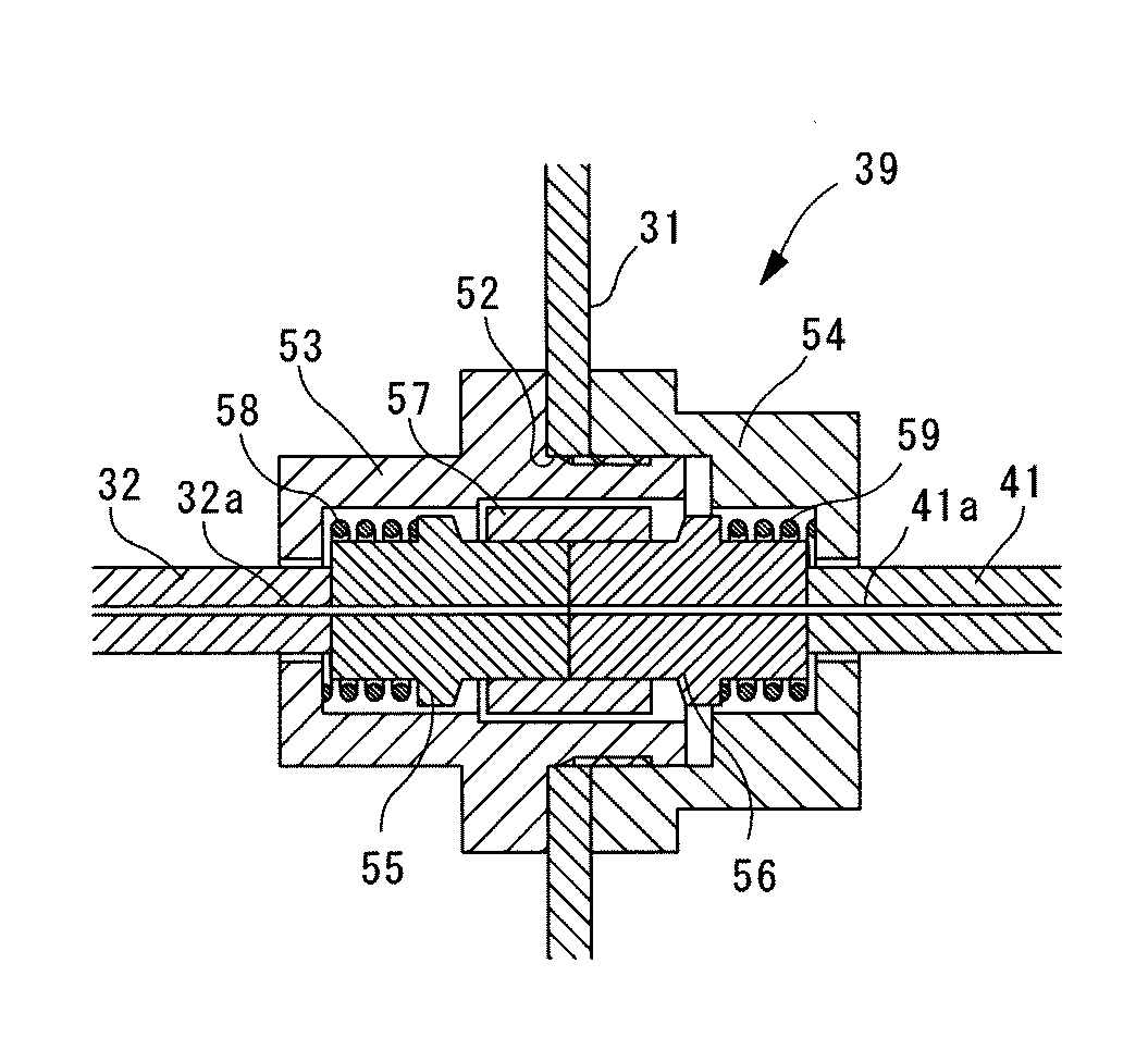
装置本体31の出口にはコネクタ39が設けられており、前記光分岐部33において分岐された一方の光ファイバ32が接続されている。また、装置本体31の外側には、生体A組織表面に接触させられる測定プローブ40が設けられ、該測定プローブ40と前記コネクタ39とが照射用光ファイバ41によって接続されている。コネクタ39による光ファイバ32,41の接続を図5に示す。コネクタ39は、相互に締結されて装置本体31の壁面にあけた貫通穴52に取り付けられるハウジング53,54と、各光ファイバ32,41のシース先端から口出しされた心線32a,41aに取り付けられるフェルール55,56とこれらフェルール55,56の突き当て部を覆うように配されるスリーブ57とフェルール55,56どうしを押しつけるように付勢力を作用させるコイルバネ58,59とを備えている。
A
コネクタ39による光ファイバ32,41の接続は、同径のコアを有する光ファイバ32,41の端面どうしを突き当てるように配置することにより行われている。光ファイバ32,41の端面は、例えば、PC研磨されており、一方の光ファイバ32の端面から発せられた測定光を効率よく他方の光ファイバ41内に引き渡すことができるようになっている。また、光ファイバ41もコア径50μmのマルチモードファイバである。したがって、相互に突き当てるように配置された光ファイバ32,41のコア径は同一であるので、光ファイバ32内を導光されてきた光は光ファイバ41に漏れなく引き渡されるようになっている。一方、ハウジング53,54の締結を緩めることにより、2本の光ファイバ32,41を簡単に切り離すことができるようになっている。これにより、保守時あるいは交換時には、コネクタ39を緩めて測定プローブ40を装置本体31から取り外すことができ、使用時には、ハウジング53,54どうしを締結するだけで簡単に取り付けることができるようになっている。
Connection of the
前記測定プローブ40には、その先端面40aに、図6に示されるように、中心に1本の照射用光ファイバ41が配置され、その周囲に間隔をあけて複数本、例えば、8本の受光用光ファイバ42が配置されている。これらの受光用光ファイバ42は、例えば、コア径200μmのマルチモードファイバである。すなわち、測定プローブ40の先端面40aを生体A組織表面に密着させた状態で装置を作動させることにより、測定プローブ40の中心から出射された測定光は、生体A内に入射され、拡散あるいは透過させられた後に、生体A表面に戻り、照射用光ファイバ41の周囲に配置されている受光用光ファイバ42によって信号光として受光されるようになっている。
As shown in FIG. 6, the
各受光用光ファイバ42と照射用光ファイバ41との間の距離は、照射用光ファイバ41から出射された測定光が、所定の光路長を経て受光用光ファイバ42に受光されるような距離に設定されている。本実施形態に係るグルコース濃度測定装置1の場合には、グルコースを多く含む真皮領域にまで測定光が進達するように、約0.4〜0.8mmの距離をあけて配置されている。これにより、受光用光ファイバ42により受光される信号光は、生体A組織内を真皮の深さまで進達した光を多く含んでいるようになる。受光用光ファイバ42は、束ねられることによりファイババンドルを形成し、他のコネクタ43により装置本体31に接続されている。
The distance between each light receiving
前記光検出部5は、2つの光検出器44,45を備えている。これら光検出器44,45は、例えば、PbSセンサ、あるいは、InGaAsセンサである。一方の参照光検出器44は、上述したように、光分岐部33において分岐された一方の光ファイバ36の端面に対向配置されており、該光ファイバ36から出射されてきた参照光を検出して検出信号を出力するようになっている。また、他方の信号光検出器45は、前記ファイババンドルを構成している受光用光ファイバ42の端面に対向して配置されており、これら受光用光ファイバ42により受光され伝播されてきた信号光を検出して検出信号を出力するようになっている。
The
前記演算部6は、前記信号光検出器45の検出信号および前記参照光検出器44の検出信号をそれぞれ増幅するアンプ46と、該アンプ46から出力された電気信号から特定の周波数の信号のみを抽出するロックイン検波器47と、該ロックイン検波器47から出力された電気信号をディジタル信号に変換するA/D変換器48と、該A/D変換器48から出力されたディジタル信号に基づいてグルコース濃度を算出するコンピュータ49とを備えている。
The
前記ロックイン検波器47は、前記フィルタ制御部26から供給された高周波を受信して、アンプ46からの電気信号から、高周波の周波数に一致する周波数成分の電気信号のみを抽出するようになっている。
また、コンピュータ49は、ロックイン検波器47により抽出された電気信号をA/D変換した出力信号と、前記フィルタ制御部26から供給された高周波の周波数に対応してAOTF25から発せられる光の波長信号とを入力されるようになっている。
The lock-in
The
これにより、コンピュータ49においては、A/D変換器48から得られた複数の出力信号と、フィルタ制御部26から得られた各出力信号に対応する波長信号とから得られる出力信号のスペクトル分布に基づいて、特定の波長領域、例えば、波長1600nm近傍の領域における出力信号値からグルコース濃度が演算されるようになっている。
なお、コンピュータ49には、ディスプレイ(図示略)が備えられており、コンピュータ49において演算されたグルコース濃度値が表示されるようになっている。
Thereby, in the
The
このように構成された本実施形態に係るグルコース濃度測定装置1の作用について、以下に説明する。
本実施形態に係るグルコース濃度測定装置1を用いて生体A内の体液のグルコース濃度を測定するには、測定プローブ40の先端面40aを生体A、例えば、指先の表面に密着させる。なお、測定部位は、指先の他、掌、前腕等でもよい。
The operation of the glucose
In order to measure the glucose concentration of the body fluid in the living body A using the glucose
この状態で、光照射部4を作動させる。光照射部4の全ての広帯域光源7〜11が作動させられることにより、広帯域光源7〜11から発せられた各波長帯域の光が光ファイバ24の端面に漏れなく入射される。そして、光ファイバ24内を伝達されてきた各波長帯域の光は、マルチプレクサ12の各入射部13〜17に入射される。種々の異なる波長帯域を有する複数の光はマルチプレクサ12において順次合波され、全ての波長帯域の光が合波された状態でマルチプレクサ12の出射部18から出射される。
In this state, the light irradiation unit 4 is operated. By operating all the broadband light sources 7 to 11 of the light irradiation unit 4, the light of each wavelength band emitted from the broadband light sources 7 to 11 is incident on the end face of the
この場合において、本実施形態に係るグルコース濃度測定装置1によれば、グルコースに特徴的な吸収特性を有する波長帯域の光ほど優先的に出射部18に近い位置で入射させ、優先度が低い波長帯域は出射部18から離すように設定されているので、グルコースに特徴的な吸収特性を有する光は、ダイクロイックミラー20〜23への入射回数が少なくなっている。したがって、グルコースに特徴的な吸収特性を有する光ほど、ダイクロイックミラー20〜23への入射による損失が少なくて済むことになる。
In this case, according to the glucose
マルチプレクサ12から出射された光は、光ファイバ29を介してAOTF25に入射される。AOTF25を作動させるには、AOTF25により分光する測定光の波長に対応する周波数の高周波をフィルタ制御部26からAOTF25に供給する。これにより、入射された光から所定波長の測定光が分光されて出射されることになる。
The light emitted from the
この場合において、本実施形態に係るグルコース濃度測定装置1によれば、AOTF25の出射部にマルチモードファイバ30が接続されているので、分光時に測定光の出射角度が変動しても、あるいは、光学系の機械的なズレや変形が生じても、AOTF25から出射された測定光はコア径の大きなマルチモードファイバ30に漏れなく入射されることになる。その結果、光源2から発せられた光が無駄なく測定プローブ40に送られるので、生体Aから得られる信号光の光量を最大限に確保することができる。そして、受光量を大きく確保することでS/N比を改善し、測定精度を向上することができるという効果がある。
In this case, according to the glucose
AOTF25から出射された測定光は、光ファイバ30を介して光分岐部33に送られ、光分岐部33においてその一部を参照光として分岐される。分岐された参照光は、参照用光ファイバ36の端面に対向配置されている参照光検出器44によりそのまま検出されることになる。
The measurement light emitted from the
参照光を分離された残りの測定光は、集光レンズ37によって、光ファイバ32内に入射されて、コネクタ39により接続されている測定プローブ40の照射用光ファイバ41に入射させられる。コネクタ39においては、同径のコアを有する光ファイバ32,41どうしの端面が突き当てられた状態に接続されているので、伝達されてきた測定光が外部に漏れることなく測定プローブ40の先端面40aから出射されることになる。
特に、光ファイバ32,41はいずれもコア径50μmのマルチモードファイバにより構成されているので、光ファイバ32から出射される測定光は漏れなく光ファイバ41内に入射され、損失が抑制されることになる。
The remaining measurement light from which the reference light has been separated is incident on the
In particular, since both the
生体A内に入射された測定光は、生体A内を進行する間に、生体A組織に衝突して拡散される。測定光は、通過する生体A組織や体液の成分に応じて、特定の波長領域の光を吸収される。したがって、生体A内で拡散されることにより生体Aの表面に戻って生体A外に出射された信号光は、通過した生体A組織や体液に応じた特定の波長領域の光量が低下していることになる。 The measurement light incident in the living body A collides with the living body A tissue and diffuses while traveling in the living body A. The measurement light absorbs light in a specific wavelength region according to the components of the living body A tissue and body fluid that pass therethrough. Therefore, the signal light that has been diffused in the living body A and returned to the surface of the living body A and emitted to the outside of the living body A has a reduced amount of light in a specific wavelength region according to the living body A tissue or body fluid that has passed through. It will be.
受光用光ファイバ42は、上述したように照射用光ファイバ41との間の距離を一定に固定されているので、その距離に応じた深さまで進達した光を多く含む信号光を受光する。本実施形態の場合には、測定光は真皮領域まで進達した後に、信号光として受光用光ファイバ42に受光されるので、受光される信号光はグルコースの情報を多く含んでいることになる。
Since the light receiving
また、本実施形態に係るグルコース濃度測定装置1によれば、照射用光ファイバ41が受光用光ファイバ42と比較して十分に小さいコア径を有しているので、照射用光ファイバ41は生体Aに対し、実質的に一点から光を入射させることになる。その結果、各受光用光ファイバ42が受光する光の生体A内における光路長の幅を狭めることができる。グルコース濃度の測定に必要な深さまで進達した光を効率的に回収して、測定精度の向上を図ることができる。
Further, according to the glucose
また、コア径の小さい照射用光ファイバ41に対して、受光用光ファイバ42を周囲に複数配置し、しかも各受光用光ファイバ42のコア径を大きく確保しているので、照射面積に対して受光面積が極めて大きく、生体A内において拡散あるいは透過された光を漏れなく回収することが可能となる。
受光された信号光は、受光用光ファイバ42を介して装置本体31内に戻され、受光用光ファイバ42の端面に対向配置されている信号光検出器45により検出される。
In addition, a plurality of light receiving
The received signal light is returned into the apparatus
信号光検出器45および参照光検出器44からの出力信号は、演算部6に入力されると、アンプ46によってそれぞれ増幅される。信号光検出器45により検出される信号光の大きさは、生体Aに入射される光、すなわち、AOTF25から発せられた測定光の強度の変動とともに変動する。したがって、生体Aへの入射前の測定光の一部を参照光として参照光検出器44により検出しておき、後述するコンピュータ49において受光された信号光から差し引くことにより、AOTF25から発せられる測定光の強度変動による信号光強度の変動を除去することが可能となる。本実施形態に係るグルコース濃度測定装置1においては、光分岐部33における分岐比率が、測定光95%、参照光5%程度に設定されているので、測定光が生体A内で減衰されて得られる信号光と参照光とのレベルを同等にして測定光の強度変動による信号光強度の変動を効果的に除去することができる。この場合に、コンピュータ49においては、参照光検出器44からの出力信号に所定の係数をかけることにより、信号レベルを調整してもよい。
When output signals from the
アンプ46において増幅された核検出器44,45からの出力信号は、それぞれロックイン検波器47を通過させられる。これにより、フィルタ制御部26からのAOTF25に入力された高周波に対応する波長の光に関する出力信号のみが抽出される。したがって、抽出された出力信号には、生体Aに入射された測定光と波長を同じくする生体Aからの散乱光の情報のみが含まれ、他の波長の光、例えば、外来光に関する情報は除かれている。その結果、外来光等によるノイズの発生を抑制することができる。
The output signals from the
そして、ロックイン検波器47において抽出された出力信号は、それぞれA/D変換器48によってディジタル信号に変換させられてコンピュータ49に入力される。フィルタ制御部26からAOTF25に入力される高周波の周波数が順次変更されており、コンピュータ49には、生体Aに入射させた測定光の波長情報が、フィルタ制御部26から順次供給される。したがって、コンピュータ49においては、出力信号と波長情報との関係を示す波長特性が求められていくことになる。また、コンピュータ49は、求めた波長特性の内、所定の波長領域、例えば、波長1600nm近傍の領域における出力信号値を求めることにより、生体A内部のグルコース濃度を演算する。そして、演算されたグルコース濃度値は、ディスプレイに表示されることになる。
The output signals extracted by the lock-in
以上説明したように、本実施形態に係るグルコース濃度測定装置1によれば、光源として広帯域光源7〜11を採用したことにより、高輝度の光を光ファイバ24内に無駄なく入射することができる。その結果、従来、ハロゲンランプのような光源からの光をファイババンドルの端面に入射させることによる無駄をなくすことができる。また、マルチプレクサ12により複数の広帯域光源7〜11からの光を合波することにより、グルコース濃度測定に必要な広い波長帯域の光を合成することができる。そして、マルチプレクサ12においては、グルコース濃度測定に有用な波長帯域の光が合波された光の中に多く含まれるようにしているので、測定精度を高めることができる。
As described above, according to the glucose
さらに、光分岐部33により、測定光の一部を参照光として分離して検出し、検出された信号光との差分をとることで測定光の強度レベルの変動による信号光強度の変動による測定精度の低下を抑制することができる。また、AOTF25の出口にマルチモードファイバ32を接続したので、AOTF25における偏光による出射角の変動、あるいは、光学系における機械的なズレや変形によってもAOTF25から出射される光を無駄なく回収して測定プローブ40に送ることができる。
Further, the optical branching
また、このように、広帯域光源7〜11からマルチプレクサ12、マルチプレクサ12からAOTF25、AOTF25から光分岐部33、光分岐33部からコネクタ39を介して測定プローブ40までを全て光ファイバ24,29,30,32,41で接続し、空間光路を最低限に抑制しているので、外部に放出される光を極力低減し、測定の効率を高めることができる。
Further, in this way, the
なお、本発明は、上述した実施形態に限定されるものではない。
第1に、光源2を5個の広帯域光源7〜11により構成することとしたが、これに代えて、2〜4個あるいは6個以上の広帯域光源を採用してもよい。
第2に、マルチプレクサ12として、複数のダイクロイックミラー20〜23を備えるものを例に挙げて説明したが、これに代えて、図7に示されるように、複数のファイバカプラ50により合波する構造のものを採用してもよい。
In addition, this invention is not limited to embodiment mentioned above.
First, the
Secondly, the
第3に、分光器3として、AOTF25を採用したが、これに代えて、グレーティングとスキャンミラーとを組み合わせたもの等を採用してもよい。
第4に、光分岐部33として、コリメートレンズ34、集光レンズ37,38およびビームスプリッタ35を組み合わせたものを例示して説明したが、これに代えて、図8に示されるように、ファイバカプラ51により分岐する構造のものにしてもよい。
Thirdly, although the
Fourthly, as the
また、上記実施形態に係るグルコース濃度測定装置1においては、受光用光ファイバ42の数を8本として説明したが、任意の数でよい。すなわち、照射用光ファイバ41と受光用光ファイバ42との間の距離と受光用光ファイバ42の外径寸法とにより、自ずと制限される。例えば、照射用光ファイバ41と受光用光ファイバ42との間の距離を0.8mmとすれば、200μmのコア径を有する受光用光ファイバを16本設置することも可能である。
In the glucose
そして、上記実施形態においては、信号光を測定する光検出器45を1個設けた例を説明したが、図9に示されるように、2個以上設けることにしてもよい。特に、受光用光ファイバ42の数が増大すると、全ての受光用光ファイバ42を束ねたファイババンドルの端面から出射される信号光を単一の光検出器45により受光することが困難になる。この場合に、サイズの大きな他の光検出器を採用することも考えられるが、光検出器はサイズの増大とともにその価格が大幅に高くなるため好ましくない。また、不要に大きな受光面積を有する光検出器は、他のノイズを拾いやすく測定精度を低下させてしまうことにもなる。そこで、ファイババンドルを複数に分割し、小さいサイズの光検出器45を複数設けることが、コスト上も精度上も好ましい。図中符号60は加算器、符号61は集光レンズである。
In the above embodiment, an example in which one
また、本実施形態に係るグルコース濃度測定装置1においては、信号光検出器45および参照光検出器44からの出力信号をそれぞれ別個のアンプ46で増幅し、別個のロックイン検波器47およびA/D変換器48を介してコンピュータ49に入力し、該コンピュータ49において差分処理を行うこととしたが、これに代えて、図10に示されるように、差動アンプ46′に入力することにより、得られた差分信号を単一のロックイン検波器47およびA/D変換器48を介してコンピュータ49に入力することにしてもよい。
In the glucose
次に、本発明の第2の実施形態に係るグルコース濃度測定装置について、図11を参照して以下に説明する。
なお、本実施形態の説明において、第1の実施形態に係るグルコース濃度測定装置1と構成を共通とする箇所に同一符号を付して説明を省略することにする。
Next, a glucose concentration measuring apparatus according to a second embodiment of the present invention will be described below with reference to FIG.
In the description of the present embodiment, portions having the same configuration as those of the glucose
本実施形態に係るグルコース濃度測定装置70は、照射用光ファイバ71において、第1の実施形態に係るグルコース濃度測定装置1と相違している。
本実施形態においては、照射用光ファイバ71は、図11に示されるように、一端をコネクタ39に接続され、他端を測定プローブ40に取り付けられている点においては第1の実施形態と同様であるが、その長さ方向の途中位置にファイバ分岐部72を備えている点、および測定プローブ40の先端面40aに分岐された複数の照射用光ファイバ71aの端面が配置されている点において相違している。
The glucose
In the present embodiment, the irradiation
ファイバ分岐部72は、図8に示した光分岐部と同様に複数のファイバカプラを用いることにより、コア径50μmの1本の照射用光ファイバ71bを、同コア径50μmの複数本、例えば4本の照射用光ファイバ71aに分岐している。
測定プローブ40においては、図12に示されるように、各照射用光ファイバ71aの端面の周囲には、同一の間隔をあけて、それぞれ6本ずつの受光用光ファイバ42が配置されている。隣接する照射用光ファイバ71aは1本または2本ずつ受光用光ファイバ42を共有しているので受光用光ファイバ42の本数は18本である。各受光用光ファイバ42のコア径は、200μmである。
The
In the
なお、受光用光ファイバ42が18本と多数であるので、図9に示したように、受光用光ファイバ42のファイババンドルを複数に分割し、小さいサイズの複数の光検出器45により検出するようにすれば、製品コストおよびノイズを削減することができるので好ましい。
Since there are as many as 18 light receiving
このように構成された本実施形態に係るグルコース濃度測定装置70の作用について以下に説明する。
本実施形態に係るグルコース測定装置70によれば、照射用光ファイバ71bがファイバ分岐部72により4本に分岐されており、その分岐された4本の照射用光ファイバ71aが測定プローブ40の先端面40aに端面を配置しているので、生体A内には、4本同時に測定光が照射される。そして、生体A内に入射された測定光は、拡散あるいは透過されることにより生体A外に信号光として戻り、各照射用光ファイバ71aの周囲に配置されている受光用光ファイバ42により受光される。
The operation of the glucose
According to the
この場合においても、照射用光ファイバ71aのコア径が十分に小さいので、測定光は異なる4点から照射されることになる。したがって、各受光用光ファイバ42に受光される信号光は、生体A内における光路長の幅が狭く、S/N比の高い信号となっている。これにより、第1の実施形態と同様に、高い測定精度でグルコース濃度を測定することができる。
Even in this case, since the core diameter of the irradiation
また、本実施形態に係るグルコース濃度測定装置70によれば、測定光が4点同時に入射されるので、いずれかの入射箇所に、測定光の入射を阻害する要因、例えば、体毛がちょうど照射用光ファイバ71aの端面を塞いでしまっているような場合においても、他のいくつかの照射用光ファイバ71aから測定光が生体A内に入射されるので、正常な測定を継続することが可能であるという効果がある。
In addition, according to the glucose
次に、本発明の第3の実施形態に係るグルコース濃度測定装置80について説明する。
本実施形態の説明において、上述した第1、第2の実施形態に係るグルコース濃度測定装置1,70と構成を共通とする箇所に同一符号を付して説明を省略する。
本実施形態に係るグルコース濃度測定装置80は、測定プローブ40の先端面40aに配置される照射用光ファイバ81aの端面と受光用光ファイバ42の端面の配列において、上記第1、第2の実施形態に係るグルコース濃度測定装置1,70と相違している。
Next, a glucose
In the description of the present embodiment, the same reference numerals are assigned to portions having the same configuration as the glucose
The glucose
図13に本実施形態に係るグルコース濃度測定装置80の測定プローブ40の先端面40aにおける光ファイバ81a,42の端面の配列例を示す。
本実施形態においては、照射用光ファイバ81aが8本備えられ、受光用光ファイバ42が7本備えられている。受光用光ファイバ42は、2本−3本−2本を3列に並べた配列で束ねられ、その周囲に間隔をあけて8本の照射用光ファイバ42が配列されている。
FIG. 13 shows an arrangement example of the end faces of the
In the present embodiment, eight irradiation
照射用光ファイバ81aがコア径50μmの光ファイバにより構成され、受光用光ファイバ42がコア径200μmの光ファイバにより構成されている点は、上記第1、第2の実施形態に係るグルコース濃度測定装置1,70と同様である。照射用光ファイバ81aは、第2の実施形態に係るグルコース濃度測定装置70と同様に、途中に配置されたファイバ分岐部72により8本に分岐され、それぞれ光源および分光器から導光されてきた測定光を端面から照射することができるようになっている。
The irradiation
このように構成された本実施形態に係るグルコース濃度測定装置80によれば、照射用光ファイバ81aから発せられた測定光は、生体A内に照射されると、全ての方向に向かって広がることになるが、その内の測定プローブ40の中心方向に向かう光が、生体A内における拡散あるいは透過の後に生体A外部において測定プローブ40の中心位置に配置されている受光用光ファイバ42のファイババンドルによって受光されることになる。
According to the glucose
この場合に、測定プローブ40の中心方向以外の方向に向かう測定光は、受光用光ファイバ42によって受光されることがなく廃棄されるため効率が低下する。しかしながら、本実施形態に係るグルコース濃度測定装置80においても、上述した第1、第2の実施形態に係るグルコース濃度測定装置1,70と同様に、小さい照射面積の照射用光ファイバ81aから発せられた光から受光用光ファイバ42により受光される信号光には、比較的狭い幅の進達度を有する信号が多く含まれる。このため、グルコース濃度の測定においてはノイズ成分が除去され測定精度が向上するという利点がある。
In this case, the measurement light traveling in a direction other than the central direction of the
また、測定プローブ40の中央部に配置した受光用光ファイバ42のファイババンドルによって、比較的大きな検出面積を確保しているので、受光される光量は十分である。なお、このファイババンドルを構成する受光用光ファイバ42の本数は7本に限定されるものではなく、7本以下でも以上でもよいし1本でもよい。
In addition, a relatively large detection area is secured by the fiber bundle of the light receiving
次に、本発明の第4の実施形態に係るグルコース濃度測定装置90について、図面を参照していかに説明する。
なお、本実施形態の説明において、第1〜第3の実施形態に係るグルコース濃度測定装置1,70,80と構成を共通とする箇所には同一の符号を付して説明を省略する。
本実施形態に係るグルコース濃度測定装置90も、第3の実施形態に係るグルコース濃度測定装置80と同様に、測定プローブ40の先端面40aにおける照射用光ファイバ91aおよび受光用光ファイバ42の配列に特徴がある。
Next, a glucose concentration measuring apparatus 90 according to a fourth embodiment of the present invention will be described with reference to the drawings.
In the description of the present embodiment, portions having the same configuration as those of the glucose
Similarly to the glucose
本実施形態は、第2の実施形態に係るグルコース濃度測定装置70と同様に、照射用光ファイバ91aを複数に分岐し、生体A内に複数の照射点から照射するとともに、各照射用光ファイバ91aの周囲に配置した複数の受光用光ファイバ42により受光する。各受光用光ファイバ42には、複数の照射用光ファイバ91aからの光が生体A内において拡散あるいは透過された後に合成されて入射されることになる。
In the present embodiment, similarly to the glucose
この場合に、生体A内において拡散あるいは透過された光は、その光路長の増加とともに急激に減衰するため、信号光として有効な光強度を有するのは、受光用光ファイバ42に近いいくつかの照射用光ファイバ91aからの光に限られる。
そこで、本実施形態に係るグルコース濃度測定装置90は、各照射用光ファイバ91aからみて、最も近い距離に配置されている受光用光ファイバ42までの距離Rの2倍以上離れた位置に、次に近い受光用光ファイバ42を配置している。
In this case, since the light diffused or transmitted in the living body A is rapidly attenuated as the optical path length increases, the light intensity effective as the signal light is limited to some of the light receiving
Therefore, the glucose concentration measuring device 90 according to the present embodiment is located next to a position at least twice the distance R to the light receiving
具体的には、図14、図16、図18に示されるように、3本または4本の照射用光ファイバ91aの周囲に、複数の受光用光ファイバ42を配置することにより構成されている。
図14に示される測定プローブ40は、3本の照射用光ファイバ91aの周囲にそれぞれ3本ずつ受光用光ファイバ42を配置したものである。各照射用光ファイバ91aとその周囲の3本の受光用光ファイバ42との間の距離Rは同一である。3本の照射用光ファイバ91aは、同一の円周上に120°の等角度間隔をあけて配置されており、その中心位置には、共通の1本受光用光ファイバ42が配置されている。
Specifically, as shown in FIGS. 14, 16, and 18, a plurality of light receiving
In the
また、一の照射用光ファイバ91aの周囲に配置されている共通の受光用光ファイバ42以外の他の2本の受光用光ファイバ42は、他の照射用光ファイバ91aからみると前記距離Rの2倍、すなわち、距離2Rより離れて配置されている。その結果、各受光用光ファイバ42が受光する光の強度は、図15に示されるように、該受光用光ファイバ42に最も近い距離Rに配置されている照射用光ファイバ91aから発せられた光の光強度が最も大きく、次に近い照射用光ファイバ91aから発せられた光の光強度は、そのわずかに数%に過ぎない程度まで減衰していることになる。
The other two light receiving
同様に、図16に示される測定プローブ40は、各照射用光ファイバ91aの周囲に、共通の受光用光ファイバ42以外に3本の受光用光ファイバ42、計4本の受光用光ファイバ42を配置したものである。これら3本の受光用光ファイバ42は、他の照射用光ファイバ91aからみると距離2Rより離れて配置されている。その結果、上記と同様、図17に示されるように、受光用光ファイバ42に最も近い照射用光ファイバ91aから発せられた光の光強度が最も大きく、次に近い照射用光ファイバ91aから発せられた光の光強度は、1%程度まで抑制されることになる。
Similarly, the
さらに、図18に示される測定プローブ40は、4本の照射用光ファイバ91aの周囲にそれぞれ等距離Rに配置される4本の受光用光ファイバ42を備える構造のものである。4本の内3本は他の照射用光ファイバ91aから距離Rの位置に配置されている。各一の照射用光ファイバ91aからみると、周囲の4個の受光用光ファイバ42は距離Rの位置に配置されているが、その他の受光用光ファイバ42は、距離2Rより離れた位置に配置されていることがわかる。逆に、各受光用光ファイバ42からみると、距離Rの位置に配置されている照射用光ファイバ91aは1本または2本であり、それ以外の照射用光ファイバ91aは距離2Rより離れた位置に配置されていることになる。
Further, the
その結果、上記の各測定プローブと同様に、図19に示されるように、距離Rの位置に配されている照射用光ファイバ91aから発せられた光の光強度が最も大きく強調され、次に近い照射用光ファイバ91aからの光は数%に抑制されることになる。
このように、照射用光ファイバ91aと受光用光ファイバ42の配置を工夫することで、特定の距離Rに配置されている照射用光ファイバ91aから生体A内に照射され、拡散または透過された後に生体A表面に放出された光を選択的に受光することが可能となり、生体A内の特定の深さの情報を多く含む信号光をピンポイントで取得することができる。したがって、信号光に含まれるノイズ成分を低減し、測定精度を向上することができる。
As a result, as in each of the measurement probes described above, as shown in FIG. 19, the light intensity of the light emitted from the irradiation
Thus, by devising the arrangement of the irradiation
次に、本発明の第5の実施形態に係るグルコース濃度測定装置について、図20を参照して以下に説明する。
本実施形態に係るグルコース濃度測定装置100も、測定プローブ40における照射用光ファイバL1〜L7および受光用光ファイバA〜Gの端面の配列を工夫するとともに、各受光用光ファイバA〜Gにより受光された信号光に対し、所定の処理を施したものである。
Next, a glucose concentration measuring apparatus according to a fifth embodiment of the present invention will be described below with reference to FIG.
The glucose concentration measuring apparatus 100 according to the present embodiment also devise the arrangement of the end faces of the irradiation optical fibers L1 to L7 and the light receiving optical fibers A to G in the
本実施形態においては、図20に示されるように、7本の照射用光ファイバL1〜L7の端面を2本−3本−2本の3列に千鳥状にピッチP=0.5で配置し、その周囲に受光用光ファイバA〜Gの端面を同一のピッチP=0.5で2次元的に規則的に配置することにより、いわゆる俵積み式に配列している。
表1に、図20において、2重円で示される受光用光ファイバA〜Gに着目したときの、各照射用光ファイバL1〜L7と受光用光ファイバA〜Gとの間の中心間距離Lを示す。また、表2に、いずれかの照射用光ファイバL1〜L7との間に同じ中心間距離Lを有する受光用光ファイバA〜Gの本数を示す。
In the present embodiment, as shown in FIG. 20, the end faces of the seven irradiation optical fibers L1 to L7 are arranged in a staggered manner with a pitch P = 0.5 in three rows of two, three, and two. In addition, the end faces of the light receiving optical fibers A to G are regularly arranged two-dimensionally at the same pitch P = 0.5 around the periphery, so that they are arranged in a so-called stacking manner.
In Table 1, the center-to-center distances between the irradiation optical fibers L1 to L7 and the light receiving optical fibers A to G when attention is paid to the light receiving optical fibers A to G indicated by double circles in FIG. L is shown. Table 2 shows the number of light receiving optical fibers A to G having the same center-to-center distance L between any of the irradiation optical fibers L1 to L7.
すなわち、これらの表1,表2によれば、6本の各受光用光ファイバAには、中心間距離0.5の位置に、照射用光ファイバL1〜L7が2本ずつ(例えば、L1,L6)隣接しているので、合計12本の照射用光ファイバL1〜L6からの第1の光強度P1の光を受光する。また、中心間距離0.866の位置に照射用光ファイバL7が1本ずつ配置されているので、合計6本の照射用光ファイバL7から第2の光強度P2の光を受光する。さらに、中心間距離1.0の位置に照射用光ファイバL1〜L7が2本ずつ(例えば、L2,L5)配置されているので、合計12本の照射用光ファイバL1〜L6から第3の光強度P3の光を受光する。以下同様である。また、受光用光ファイバB〜Gについても同様に考えることができる。 That is, according to Tables 1 and 2, each of the six light receiving optical fibers A has two irradiation optical fibers L1 to L7 at a center distance of 0.5 (for example, L1 , L6) Since they are adjacent to each other, the light of the first light intensity P1 from the total of 12 irradiation optical fibers L1 to L6 is received. In addition, since one irradiation optical fiber L7 is disposed at the center distance of 0.866, light of the second light intensity P2 is received from a total of six irradiation optical fibers L7. Furthermore, since the two irradiation optical fibers L1 to L7 (for example, L2 and L5) are arranged at the position of the center distance 1.0, the third of the 12 irradiation optical fibers L1 to L6 is the third to the third. Light of light intensity P3 is received. The same applies hereinafter. The same applies to the light receiving optical fibers B to G.
本実施形態においては、第1の光強度P1の光がグルコース濃度の測定に必要な進達度の光であるように設定している。そして、それ以外の光強度の光は、グルコース濃度の測定には不要であり、これらを除去するために以下の処理を施す。
すなわち、信号光に対する所定の処理は、各受光用光ファイバA〜Gにおいて受光された光の検出信号に重み付けをして相互に加減算することにより、生体A内を所定の深さまで進達した光の情報を抽出する処理である。処理は、コンピュータ(情報抽出手段)49により行われる。
具体的には、例えば、下式(1)の通りである。
S=−PA+3×PB−5×PC+4×PD−2×PE+2×PF−4×PG (1)
In the present embodiment, the light having the first light intensity P1 is set so as to be a light with a degree of progress necessary for measuring the glucose concentration. And the light of the other light intensity is unnecessary for the measurement of glucose concentration, and in order to remove these, the following process is performed.
That is, the predetermined processing for the signal light is performed by weighting the detection signals of the light received in the respective light receiving optical fibers A to G, and adding or subtracting them to each other, thereby allowing the light that has advanced in the living body A to a predetermined depth. This is a process of extracting information. Processing is performed by a computer (information extraction means) 49.
Specifically, for example, the following formula (1) is satisfied.
S = -
ここで、PA〜PGは、受光用光ファイバA〜Gに受光される信号光であり、以下の通りに表すことができる。
PA=12×P1+ 6×P2+12×P3+12×P4
PB= 6×P1+12×P2+ 6×P3+12×P4+6×P5
PC= 6×P2+ 6×P3+12×P4+6×P5+・・・
PD= 6×P3+12×P4+6×P5+・・・
PE= 12×P4+ ・・・
PF= 6×P4+6×P5+・・・
PG= 6×P5+・・・
Here, PA to PG are signal lights received by the light receiving optical fibers A to G, and can be expressed as follows.
PA = 12 × P1 + 6 × P2 + 12 × P3 + 12 × P4
PB = 6 × P1 + 12 × P2 + 6 × P3 + 12 × P4 + 6 × P5
PC = 6 * P2 + 6 * P3 + 12 * P4 + 6 * P5 + ...
PD = 6 * P3 + 12 * P4 + 6 * P5 + ...
PE = 12 × P4 +
PF = 6 × P4 + 6 × P5 +
PG = 6 × P5 + ...
そして、これらのPA〜PGを式(1)に当てはめると、以下の通りとなる
−PA=−12×P1− 6×P2−12×P3−12×P4
+3×PB= 18×P1+36×P2+18×P3+36×P4+18×P5
−5×PC= −30×P2−30×P3−60×P4−30×P5+・・・
+4×PD= 24×P3+48×P4+24×P5+・・・
−2×PE= −24×P4− ・・・
+2×PF= 12×p4+12×P5+・・・
−4×PG= −24×P5+・・・
S ≒ 6×P1
And, when these PA to PG are applied to the formula (1), it becomes as follows. −PA = −12 × P1−6 × P2-12 × P3-12 × P4
+ 3 × PB = 18 × P1 + 36 × P2 + 18 × P3 + 36 × P4 + 18 × P5
−5 × PC = −30 × P2-30 × P3-60 × P4-30 × P5 +...
+ 4 * PD = 24 * P3 + 48 * P4 + 24 * P5 + ...
-2 × PE = −24 × P4-
+ 2 × PF = 12 × p4 + 12 × P5 +.
−4 × PG = −24 × P5 +
S ≒ 6 x P1
これにより、グルコース濃度の測定に必要な第1の光強度P1の光のみを残し、他の不要な光強度P2以降の成分を代数的に消去することができる。受光用光ファイバA〜Gから十分に遠い照射用光ファイバL1〜L7からの光の光強度(本実施形態では光強度P6以上)は誤差範囲内であり無視できる。したがって、生体A内を所定の深さまで進達した光の情報を選択的に抽出することができるので、グルコース濃度の測定を精度よく行うことが可能となる。 Thereby, only the light of the first light intensity P1 necessary for the measurement of the glucose concentration can be left, and other unnecessary components after the light intensity P2 can be algebraically deleted. The light intensity of light from the irradiation optical fibers L1 to L7 sufficiently far from the light receiving optical fibers A to G (in the present embodiment, the light intensity P6 or more) is within an error range and can be ignored. Therefore, since it is possible to selectively extract the information of the light that has reached the living body A to a predetermined depth, it is possible to measure the glucose concentration with high accuracy.
なお、上記重み付けは一例であり、他の式に当てはめることにしてもよい。また、俵積み配列の場合について説明したが、格子状配列その他の配列でもよい。さらに、前記光源7は、広帯域光源に代えて、例えば、ハロゲンランプ、キセノンランプ、メタルハライドランプ、高圧水銀ランプ等の他の光源でもよい。また、照射用光ファイバおよび受光用光ファイバの数は任意でよい。 The weighting is an example, and may be applied to another formula. Moreover, although the case of the stacked arrangement has been described, a lattice arrangement or other arrangement may be used. Further, the light source 7 may be another light source such as a halogen lamp, a xenon lamp, a metal halide lamp, or a high-pressure mercury lamp instead of the broadband light source. Further, the number of irradiation optical fibers and light receiving optical fibers may be arbitrary.
A 生体
1 グルコース濃度測定装置
2 光源
7〜11 広帯域光源
12 マルチプレクサ(合波手段)
31 装置本体
32 装置内光ファイバ
40 測定プローブ
40a 先端面
41,71,71a,71b,91a 照射用光ファイバ
42 受光用光ファイバ
45 光検出器
49 コンピュータ(情報抽出手段)
A living
DESCRIPTION OF
Claims (12)
生体表面に略接触状態に配置され、光源からの光を生体内に向けて照射する測定プローブと、
これら装置本体と測定プローブとを着脱可能に接続する照射用光ファイバとを備え、
該照射用光ファイバの一端面が測定プローブの先端面に固定され、他端面が装置内光ファイバの端面に突き当てられた状態で前記装置本体に取り付けられるグルコース濃度測定装置。 A device body comprising a light source and a single intra-device optical fiber that guides light emitted from the light source;
A measurement probe which is arranged in a substantially contact state on the surface of the living body and irradiates light from the light source toward the living body;
An irradiating optical fiber that detachably connects the apparatus main body and the measurement probe,
A glucose concentration measuring apparatus attached to the apparatus main body with one end face of the irradiation optical fiber fixed to the distal end face of the measurement probe and the other end faced against the end face of the optical fiber in the apparatus.
前記測定プローブの先端面に、前記照射用光ファイバの端面および該照射用光ファイバの端面の周囲に半径方向に所定間隔をあけて配される受光用光ファイバの端面が配置され、
各受光用光ファイバのコア径が、照射用光ファイバのコア径より大きいグルコース濃度測定装置。 An apparatus main body including a light source that generates light to irradiate a living body, a light detector that detects light diffused or transmitted in the living body, and an irradiation optical fiber that emits light from the light source toward the living body. A plurality of light receiving optical fibers that receive light from within the living body and guide the light to the photodetector, end faces of the irradiation optical fibers, and a predetermined interval in the radial direction around the end faces of the irradiation optical fibers. A measuring probe for bringing a distal end surface on which an end surface of an optical fiber for receiving light arranged to be placed into contact with a living body surface;
On the tip surface of the measurement probe, an end face of the light receiving optical fiber disposed at predetermined intervals in the radial direction around the end face of the irradiation optical fiber and the end face of the irradiation optical fiber is disposed,
A glucose concentration measuring device in which the core diameter of each light receiving optical fiber is larger than the core diameter of the irradiation optical fiber.
照射用光ファイバが複数に分岐され、
各照射用光ファイバの端面が、前記受光用光ファイバの端面の周囲に半径方向に所定間隔をあけて配置され、
各受光用光ファイバのコア径が、照射用光ファイバのコア径より大きいグルコース濃度測定装置。 An apparatus main body including a light source that generates light to irradiate a living body, a light detector that detects light diffused or transmitted in the living body, and an irradiation optical fiber that emits light from the light source toward the living body. A light receiving optical fiber that receives light from within the living body and guides it to the photodetector, and an end face on which the end face of the irradiation optical fiber and the end face of the receiving optical fiber are placed in contact with the living body surface With a measurement probe,
The irradiation optical fiber is branched into a plurality of
End surfaces of the respective irradiation optical fibers are arranged at predetermined intervals in the radial direction around the end surfaces of the light receiving optical fibers,
A glucose concentration measuring device in which the core diameter of each light receiving optical fiber is larger than the core diameter of the irradiation optical fiber.
照射用光ファイバが複数に分岐され、
各照射用光ファイバの端面の周囲に半径方向に所定間隔をあけて、複数の受光用光ファイバの端面が配置され、
各受光用光ファイバのコア径が、照射用光ファイバのコア径より大きく設定され、
各照射用光ファイバからみて、最も近い距離に配置されている受光用光ファイバまでの距離の2倍より離れた位置に、次に近い受光用光ファイバが配置されているグルコース濃度測定装置。 An apparatus main body including a light source that generates light to irradiate a living body, a light detector that detects light diffused or transmitted in the living body, and an irradiation optical fiber that emits light from the light source toward the living body. A light receiving optical fiber that receives light from within the living body and guides it to the photodetector, and an end face on which the end face of the irradiation optical fiber and the end face of the receiving optical fiber are placed in contact with the living body surface With a measurement probe,
The irradiation optical fiber is branched into a plurality of
End surfaces of a plurality of light receiving optical fibers are arranged at predetermined intervals in the radial direction around the end surface of each irradiation optical fiber,
The core diameter of each light receiving optical fiber is set larger than the core diameter of the irradiation optical fiber,
A glucose concentration measuring device in which the next closest receiving optical fiber is arranged at a position more than twice the distance to the receiving optical fiber arranged at the closest distance when viewed from each irradiation optical fiber.
各受光用光ファイバにおいて受光された光の検出信号に重み付けをして相互に加減算することにより、生体内を所定の深さまで進達した光の情報を抽出する情報抽出手段を備えるグルコース濃度測定装置。 An apparatus body including a light source that generates light to irradiate a living body, a light detector that detects light diffused or transmitted in the living body, and a plurality of irradiation lights that emit light from the light source toward the living body A fiber, a plurality of light receiving optical fibers that receive light from the living body and guide the light to the photodetector, and a tip on which the end surfaces of the irradiation optical fiber and the light receiving optical fiber are regularly arranged A measuring probe for bringing the surface into contact with the living body surface,
A glucose concentration measuring apparatus comprising an information extracting means for extracting information on light that has progressed to a predetermined depth in a living body by weighting detection signals of light received in each optical fiber for light reception and adding and subtracting each other.
Priority Applications (1)
| Application Number | Priority Date | Filing Date | Title |
|---|---|---|---|
| JP2003435182A JP2005192612A (en) | 2003-12-26 | 2003-12-26 | Glucose concentration measuring apparatus |
Applications Claiming Priority (1)
| Application Number | Priority Date | Filing Date | Title |
|---|---|---|---|
| JP2003435182A JP2005192612A (en) | 2003-12-26 | 2003-12-26 | Glucose concentration measuring apparatus |
Publications (1)
| Publication Number | Publication Date |
|---|---|
| JP2005192612A true JP2005192612A (en) | 2005-07-21 |
Family
ID=34815380
Family Applications (1)
| Application Number | Title | Priority Date | Filing Date |
|---|---|---|---|
| JP2003435182A Withdrawn JP2005192612A (en) | 2003-12-26 | 2003-12-26 | Glucose concentration measuring apparatus |
Country Status (1)
| Country | Link |
|---|---|
| JP (1) | JP2005192612A (en) |
Cited By (5)
| Publication number | Priority date | Publication date | Assignee | Title |
|---|---|---|---|---|
| JPS6261827A (en) * | 1985-09-11 | 1987-03-18 | Shinko Electric Co Ltd | Tractive wheel mechanism for all-direction transfer car |
| JP2014222197A (en) * | 2013-05-14 | 2014-11-27 | 東ソー株式会社 | Differential refractometer |
| JP2014232120A (en) * | 2007-10-12 | 2014-12-11 | エスペ3アッシュ | Spectrum measurement device for fluid analysis |
| WO2020158348A1 (en) * | 2019-01-31 | 2020-08-06 | 国立大学法人東北大学 | Device and method for measuring blood sugar level |
| WO2020240015A3 (en) * | 2019-05-29 | 2021-01-07 | Colvistec Ag | Multi-fibre optical probe |
-
2003
- 2003-12-26 JP JP2003435182A patent/JP2005192612A/en not_active Withdrawn
Cited By (8)
| Publication number | Priority date | Publication date | Assignee | Title |
|---|---|---|---|---|
| JPS6261827A (en) * | 1985-09-11 | 1987-03-18 | Shinko Electric Co Ltd | Tractive wheel mechanism for all-direction transfer car |
| JP2014232120A (en) * | 2007-10-12 | 2014-12-11 | エスペ3アッシュ | Spectrum measurement device for fluid analysis |
| JP2014222197A (en) * | 2013-05-14 | 2014-11-27 | 東ソー株式会社 | Differential refractometer |
| WO2020158348A1 (en) * | 2019-01-31 | 2020-08-06 | 国立大学法人東北大学 | Device and method for measuring blood sugar level |
| CN113260849A (en) * | 2019-01-31 | 2021-08-13 | 国立大学法人东北大学 | Blood sugar level measuring device and blood sugar level measuring method |
| JPWO2020158348A1 (en) * | 2019-01-31 | 2021-12-02 | 国立大学法人東北大学 | Blood glucose measuring device and blood glucose measuring method |
| WO2020240015A3 (en) * | 2019-05-29 | 2021-01-07 | Colvistec Ag | Multi-fibre optical probe |
| US11988588B2 (en) | 2019-05-29 | 2024-05-21 | Colvistec Ag | Multi-fibre optical probe |
Similar Documents
| Publication | Publication Date | Title |
|---|---|---|
| US10531790B2 (en) | Method and system of spectrally encoded imaging | |
| US10213113B2 (en) | Physiological measurement device using light emitting diodes | |
| US8804115B2 (en) | Systems and methods for performing optical spectroscopy using a self-calibrating fiber optic probe | |
| US7952706B2 (en) | Multi-channel fiber optic spectroscopy systems employing integrated optics modules | |
| CN100522059C (en) | Non-intruding measurer for value of blood sugar | |
| JP4429886B2 (en) | Optical tomography system | |
| US10996402B2 (en) | Multi-channel optical fiber rotary junction | |
| US20110313299A1 (en) | Several measurement modalities in a catheter-based system | |
| WO2014124531A1 (en) | Integrated spectral probe for raman, reflectance and fluorescence spectral measurements | |
| JP2014520645A (en) | Non-invasive device and method for measuring bilirubin levels | |
| EP2896347B1 (en) | Scattered light measurement device | |
| US10670530B2 (en) | Raman probe and Raman spectrum measuring device | |
| US20080300473A1 (en) | Stabilized Multi-Wavelength Laser System for Non-Invasive Spectrophotometric Monitoring | |
| JP2005192612A (en) | Glucose concentration measuring apparatus | |
| JP2011147705A (en) | Diagnostic assisting device, optical probe, and operation method of the same diagnostic assisting device | |
| JP2005224530A (en) | Glucose concentration measuring apparatus | |
| JP2004147706A (en) | Apparatus and method for determining non-invasive biomedical component | |
| JP2005265592A (en) | Glucose concentration measuring apparatus | |
| JP2005224536A (en) | Glucose concentration measuring device | |
| JP2005192611A (en) | Glucose concentration measuring apparatus | |
| JP2009233404A (en) | Non-invasive type quantifying instrument of biological component | |
| JP2006132986A (en) | Optical biological information measuring instrument and measuring method using it | |
| JP2005312743A (en) | Glucose concentration measuring apparatus | |
| JP2005296386A (en) | Glucose meter | |
| JP2011130902A (en) | Optical probe |
Legal Events
| Date | Code | Title | Description |
|---|---|---|---|
| A300 | Withdrawal of application because of no request for examination |
Free format text: JAPANESE INTERMEDIATE CODE: A300 Effective date: 20070306 |