JP2005134822A - Optical connector adapter - Google Patents
Optical connector adapter Download PDFInfo
- Publication number
- JP2005134822A JP2005134822A JP2003373390A JP2003373390A JP2005134822A JP 2005134822 A JP2005134822 A JP 2005134822A JP 2003373390 A JP2003373390 A JP 2003373390A JP 2003373390 A JP2003373390 A JP 2003373390A JP 2005134822 A JP2005134822 A JP 2005134822A
- Authority
- JP
- Japan
- Prior art keywords
- shell
- optical connector
- flange portion
- flange
- shell body
- Prior art date
- Legal status (The legal status is an assumption and is not a legal conclusion. Google has not performed a legal analysis and makes no representation as to the accuracy of the status listed.)
- Granted
Links
- 230000003287 optical effect Effects 0.000 title claims description 105
- 230000002093 peripheral effect Effects 0.000 claims description 7
- 230000004308 accommodation Effects 0.000 abstract description 6
- 239000013307 optical fiber Substances 0.000 description 8
- 239000011347 resin Substances 0.000 description 4
- 229920005989 resin Polymers 0.000 description 4
- 239000002184 metal Substances 0.000 description 2
- 238000000465 moulding Methods 0.000 description 2
Images


Classifications
-
- G—PHYSICS
- G02—OPTICS
- G02B—OPTICAL ELEMENTS, SYSTEMS OR APPARATUS
- G02B6/00—Light guides; Structural details of arrangements comprising light guides and other optical elements, e.g. couplings
- G02B6/24—Coupling light guides
- G02B6/36—Mechanical coupling means
- G02B6/38—Mechanical coupling means having fibre to fibre mating means
- G02B6/3807—Dismountable connectors, i.e. comprising plugs
- G02B6/381—Dismountable connectors, i.e. comprising plugs of the ferrule type, e.g. fibre ends embedded in ferrules, connecting a pair of fibres
- G02B6/3825—Dismountable connectors, i.e. comprising plugs of the ferrule type, e.g. fibre ends embedded in ferrules, connecting a pair of fibres with an intermediate part, e.g. adapter, receptacle, linking two plugs
-
- G—PHYSICS
- G02—OPTICS
- G02B—OPTICAL ELEMENTS, SYSTEMS OR APPARATUS
- G02B6/00—Light guides; Structural details of arrangements comprising light guides and other optical elements, e.g. couplings
- G02B6/24—Coupling light guides
- G02B6/36—Mechanical coupling means
- G02B6/38—Mechanical coupling means having fibre to fibre mating means
- G02B6/3807—Dismountable connectors, i.e. comprising plugs
- G02B6/389—Dismountable connectors, i.e. comprising plugs characterised by the method of fastening connecting plugs and sockets, e.g. screw- or nut-lock, snap-in, bayonet type
Landscapes
- Physics & Mathematics (AREA)
- General Physics & Mathematics (AREA)
- Optics & Photonics (AREA)
- Mechanical Coupling Of Light Guides (AREA)
Abstract
【課題】 部分点数を削減すること、省スペース化に対応すること、組立作業を簡易化し作業工数を削減すること。
【解決手段】 第1のフランジ部13aの開口部13eに収容フランジ部17aが入り込む際に前記第1のフランジ部13aによって係合部17eが押圧され前記収容フランジ部17aの一部分17sを弾性変形するように前記係合部17eの近傍の前記収容フランジ部17aの前記一部分17sにスリット17gを形成することによって第1のシェル体11を組み立てる。
【選択図】 図1PROBLEM TO BE SOLVED: To reduce the number of partial points, cope with space saving, simplify assembly work and reduce work man-hours.
When an accommodation flange portion 17a enters an opening 13e of a first flange portion 13a, an engagement portion 17e is pressed by the first flange portion 13a to elastically deform a portion 17s of the accommodation flange portion 17a. Thus, the first shell body 11 is assembled by forming a slit 17g in the portion 17s of the receiving flange portion 17a in the vicinity of the engaging portion 17e.
[Selection] Figure 1
Description
本発明は、一対の光コネクタプラグを光学的に接続する光コネクタアダプタに関する。 The present invention relates to an optical connector adapter that optically connects a pair of optical connector plugs.
先行技術としては、第1の光コネクタプラグを挿入する第1のシェル体と、第1のシェル体に結合・分離可能に締結され第2の光コネクタプラグを挿入する第2のシェル体とを含み、第1及び第2のシェル体に第1及び第2の光コネクタプラグを相対的に挿入して接続することにより前記第1及び第2の光コネクタプラグを光学的に接続する光コネクタアダプタが知られている(例えば、特許文献1を参照)。 As a prior art, a first shell body into which a first optical connector plug is inserted, and a second shell body into which the second optical connector plug is inserted after being fastened to the first shell body so as to be coupled and separable. An optical connector adapter that optically connects the first and second optical connector plugs by relatively inserting and connecting the first and second optical connector plugs to the first and second shell bodies. Is known (see, for example, Patent Document 1).
また、他の光コネクタアダプタとしては、ロックレバーを有し、このロックレバーに弾性部材を設け、リアフランジに弾性部材を円軌道に沿って回動させたときに突き当たる係合突部を設けたものがある(例えば、特許文献2を参照)。
解決しようとする問題点は、光コネクタアダプタの構成として内ばね、第1の外郭部材、第2の外郭部材、などの部材を必要とするため部分点数が多くなるという問題がある。 The problem to be solved has a problem that the number of partial points increases because members such as an inner spring, a first outer member, and a second outer member are required as the configuration of the optical connector adapter.
また、光コネクタアダプタの構成が複雑であり、大きな外郭形状となるので省スペース化できないという問題がある。 In addition, the configuration of the optical connector adapter is complicated, and there is a problem that space saving cannot be achieved because of a large outer shape.
さらに、組立作業には、特別な治工具を必要とすることから作業工数が増大し、作業を簡易化することができない点である。 Furthermore, the assembly work requires special jigs and tools, which increases the number of work steps, and the work cannot be simplified.
また、ロックレバーを有する光コネクタでは、ロックレバーに特別な部材としての弾性部材を設けなければならず、取り付け作業を簡易化することができないという問題がある。 Further, in an optical connector having a lock lever, there is a problem that an elastic member as a special member must be provided on the lock lever, and the mounting operation cannot be simplified.
本発明は、第1の光コネクタプラグを第1の方向へ挿入する第1のシェル体と、該第1のシェル体に結合・分離可能に締結され第2の光コネクタプラグを前記第1の方向とは逆向きの第2の方向へ挿入する第2のシェル体とを含み、前記第1及び第2のシェル体に前記第1及び第2の光コネクタプラグを前記第1及び第2の方向へ相対的に挿入して接続することにより前記第1及び第2の光コネクタプラグを光学的に接続する光コネクタアダプタにおいて、前記第1のシェル体は、第1のシェル部材と、該第1のシェル部材に保持している収容部材とを有し、前記第1のシェル部材は、第1のフランジ部と、該第1のフランジ部に接続されている第1のシェル筒部とを有し、
前記第1のフランジ部は前記第1のシェル筒部に連通している開口部と、前記第1のフランジ部に形成した第1の係合受部とを有し、前記収容部材は、前記第1のフランジ部の前記開口部内に入り込む収容フランジ部を有し、前記収容フランジ部は、前記第1の係合受部に係合するよう前記第1のフランジ部の前記第1の係合受部に対向させるように形成した係合部と、前記第1のフランジ部の開口部に前記収容フランジ部が入り込む際に前記第1のフランジ部によって前記係合部が押圧され前記収容フランジ部の一部分を弾性変形するように前記係合部の近傍の前記収容フランジ部の前記一部分に形成したスリットとを有していることを特徴とする光コネクタアダプタであることを最も主要な特徴とする。
The present invention includes a first shell body for inserting a first optical connector plug in a first direction, and a second optical connector plug fastened to the first shell body so as to be coupled / separable to the first shell body. A second shell body that is inserted in a second direction opposite to the direction, and the first and second optical connector plugs are inserted into the first and second shell bodies. In the optical connector adapter for optically connecting the first and second optical connector plugs by inserting and connecting them relative to each other in the direction, the first shell body includes a first shell member and the first shell member. And a first shell member connected to the first flange portion. The housing member is held by one shell member. The first shell member includes a first flange portion and a first shell tube portion connected to the first flange portion. Have
The first flange portion includes an opening communicating with the first shell tube portion, and a first engagement receiving portion formed on the first flange portion, and the housing member includes: The first flange portion has a receiving flange portion that enters into the opening portion, and the receiving flange portion engages with the first engagement receiving portion so that the first engagement of the first flange portion is performed. An engaging portion formed to face the receiving portion; and the receiving flange portion is pressed by the first flange portion when the receiving flange portion enters the opening of the first flange portion. The optical connector adapter is characterized in that it has a slit formed in the part of the receiving flange part in the vicinity of the engaging part so as to elastically deform a part of the optical connector adapter. .
また、本発明は、第1の光コネクタプラグを第1の方向へ挿入する第1のシェル体と、該第1のシェル体に結合・分離可能に締結され第2の光コネクタプラグを前記第1の方向とは逆向きの第2の方向へ挿入する第2のシェル体とを含み、
前記第1及び第2のシェル体に前記第1及び第2の光コネクタプラグを前記第1及び第2の方向から相対的に挿入して接続することにより前記第1及び第2の光コネクタプラグを光学的に接続する光コネクタアダプタにおいて、前記第1のシェル体は、第1のシェル部材を有し、前記第1のシェル部材は、第1のフランジ部と、前記パネルの前記孔に挿入可能に前記第1のフランジ部に接続されているシェル筒部とを有し、前記第1のフランジ部の外周面には、前記第2のシェル体を前記第1のフランジ部に係合する第1の係合受部と、前記第2のシェル体を前記第1のフランジ部にロックする第2の係合受部とを有し、前記第2のシェル体は、前記第1のフランジ部に取り付けられる第2のシェル部材と、該第1のシェル部材の前記第1の係合受部に係合し前記第2の係合受部にロックするよう取り付けたロックレバーとを有し、前記第2のシェル部材は、前記ロックレバーを前記第1及び第2のシェル部材の相互間で円軌道に沿って回動可能に支持した回動軸を有し、前記ロックレバーは、前記円軌道上で前記第1の係合受部に係合する第1のレバー係合部と、前記第1の係合受部に前記第1のレバー係合部が係合した際に前記第1及び前記第2のシェル部材のロック状態を保持するように前記第2の係合受部に係合してロック状態を維持する第2のレバー係合部とを有し、前記第2のフランジ部は、前記第2のレバー係合部によって前記第2の係合受部を押圧して前記第1のフランジ部の一部分を弾性変形するように前記第2の係合受部の近傍の前記第2のフランジ部の前記一部分に形成したスリットを有していることを特徴とする光コネクタアダプタであることを最も主要な特徴とする。
The present invention also provides a first shell body for inserting the first optical connector plug in the first direction and a second optical connector plug fastened to the first shell body so as to be coupled / separable. A second shell body inserted in a second direction opposite to the first direction,
The first and second optical connector plugs are connected by inserting the first and second optical connector plugs relative to the first and second shell bodies from the first and second directions. In the optical connector adapter for optically connecting the first shell body, the first shell body includes a first shell member, and the first shell member is inserted into the first flange portion and the hole of the panel. And a shell cylinder portion connected to the first flange portion, and the second shell body is engaged with the first flange portion on an outer peripheral surface of the first flange portion. A first engagement receiving portion; and a second engagement receiving portion for locking the second shell body to the first flange portion, wherein the second shell body includes the first flange. A second shell member attached to the portion, and the first shell member of the first shell member A locking lever that is engaged with the receiving portion and is locked to the second engagement receiving portion, and the second shell member includes the locking lever of the first and second shell members. A first lever engaging portion that has a rotation shaft that is rotatably supported along a circular orbit between each other, and the lock lever engages with the first engagement receiving portion on the circular orbit. And when the first lever engaging portion is engaged with the first engagement receiving portion, the second engagement receiving portion is held so that the locked state of the first and second shell members is maintained. A second lever engaging portion that engages with the portion and maintains the locked state, and the second flange portion presses the second engagement receiving portion by the second lever engaging portion. The second flange portion in the vicinity of the second engagement receiving portion so as to elastically deform a part of the first flange portion. The most important feature that is an optical connector adapter, characterized in that a slit formed in the portion.
本発明の光コネクタアダプタによれば、収容フランジ部の一部分にスリットを形成することにより第1のシェル体の係合における部分点数を削減できる。 According to the optical connector adapter of the present invention, the number of partial points in the engagement of the first shell body can be reduced by forming a slit in a part of the housing flange portion.
また、第2のシェル体における第2のフランジ部の一部分にスリットを形成することにより、第2のシェル体の部分点数を削減できる。 Further, by forming a slit in a part of the second flange portion in the second shell body, the number of partial points of the second shell body can be reduced.
また、光コネクタアダプタの機構部分を最小限に抑えることができ省スペース化が可能となる。 In addition, the mechanical portion of the optical connector adapter can be minimized and space saving can be achieved.
さらに、光コネクタアダプタの組立作業には、特別な治工具を必要としないことから、作業工数を大幅に削減でき、作業の簡易化が可能となるという利点がある。 Furthermore, the assembly work of the optical connector adapter does not require any special jigs and tools, so that the number of work steps can be greatly reduced and the work can be simplified.
本発明の光コネクタアダプタでは、第1のシェル体における第1のシェル部材の第1のフランジ部の開口部に収容フランジ部が入り込む際に第1のフランジ部によって係合部が押圧され収容フランジ部の一部分を弾性変形するように係合部の近傍の収容フランジ部の一部分にスリットを形成することによって第1のシェル体と第2のシェル体との係合及びロック状態を維持することを実現した。 In the optical connector adapter of the present invention, the engaging portion is pressed by the first flange portion when the accommodating flange portion enters the opening of the first flange portion of the first shell member in the first shell body, and the accommodating flange is pressed by the first flange portion. Maintaining the engagement and the locked state of the first shell body and the second shell body by forming a slit in a part of the housing flange part in the vicinity of the engagement part so as to elastically deform a part of the part. It was realized.
また、本発明の光コネクタアダプタでは、第2のシェル体における第2のシェル部材の第2のフランジ部に、第2のレバー係合部によって第2の係合受部を押圧して第1のフランジ部の一部分を弾性変形するように第2の係合受部の近傍の第2のフランジ部の一部分にスリットを形成し、第1のシェル体と前記第2のシェル体との係合及びロック状態を維持することを実現した。 In the optical connector adapter of the present invention, the second engagement receiving portion is pressed by the second lever engaging portion against the second flange portion of the second shell member in the second shell body. A slit is formed in a portion of the second flange portion in the vicinity of the second engagement receiving portion so as to elastically deform a portion of the flange portion of the first shell body and the engagement between the first shell body and the second shell body. And the lock state was realized.
図1は、本発明の実施例1に係る光コネクタアダプタを示しており、第1の光コネクタプラグ及び第2の光コネクタプラグを光コネクタアダプタに接続した状態を示している。図2は、図1に示した光コネクタアダプタ、第1の光コネクタプラグ、及び第2の光コネクタプラグを接続状態から分解して示した側面図である。 FIG. 1 shows an optical connector adapter according to a first embodiment of the present invention, in which a first optical connector plug and a second optical connector plug are connected to the optical connector adapter. FIG. 2 is an exploded side view of the optical connector adapter, the first optical connector plug, and the second optical connector plug shown in FIG.
図1及び図2を参照して、光コネクタアダプタは、第1のシェル体11と、第1のシェル体11に結合・分離可能に締結する第2のシェル体21とを備えている。
Referring to FIGS. 1 and 2, the optical connector adapter includes a
第1のシェル体11は、機器(図示せず)のパネル31の内側で第1の光コネクタプラグ41をパネル31の第1の面31aへ向かう第1の方向Iへ挿入して接続するようにパネル31に取り付けられる。第2のシェル体21は、パネルの外側から第2の光コネクタプラグ51をパネル31の第2の面31cへ向かう第2の方向IIへ挿入して接続するようにパネル31の外側で第1のシェル体11に結合・分離可能に締結する。
The
光コネクタアダプタでは、第1及び第2の光コネクタプラグ41,51を第1及び第2のシェル体11,21に相対する方向(第1及び第2の方向I,II)から挿入して接続することにより光学的に接続するものである。
In the optical connector adapter, the first and second
さらに、図3乃至図7をも参照して以下に光コネクタアダプタを詳細に説明する。第1のシェル体11は、パネル31に形成されている孔31aに第2の方向IIで挿入されてパネル31に取り付けられる第1のシェル部材13と、パネル31の内側で第1のシェル部材13の外周面に保持されている固定用部材15と、パネル31の外部から第1のシェル部材13に保持している収容部材17とを有している。
Further, the optical connector adapter will be described in detail below with reference to FIGS. The
第1のシェル部材13は、パネル31の孔31aよりも大きい寸法でパネル31の外側の外面に対向する寸法の第1のフランジ部13aと、パネル31の孔31aに挿入可能に第1のフランジ部13aに接続されている第1のシェル筒部13cとを有している。
The
図3に示すように、第1のフランジ部13aには、第1のシェル筒部13cに連通している開口部13eと、第1のフランジ部13aの外面から開口部13e側へ貫通している孔形状の第1の係合受部13gとが設けられている。第1のシェル筒部13cには、第1の光コネクタプラグ41が第1の方向Iで挿入される側面の端面から開口部13e側へ一対の切り欠き部13jが形成されている。さらに、第1のフランジ部13aの外面には、第1の係合受部13gを形成していない相対する側面の一対の外面のそれぞれに軸部13nが設けられている。
As shown in FIG. 3, the
固定用部材15は、図1、図2及び図7に示すように、第1のシェル筒部13cの外周面に保持される固定部15aと、固定部15aに一端が接続されて第1のシェル筒部13cの外周面から離れる向きで第1のフランジ部13a側へ延びている固定用係合部15cとを有している。
As shown in FIGS. 1, 2, and 7, the
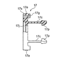
収容部材17には、第1のフランジ部13aの開口部13e内に入り込む四角形状の収容フランジ部17aと、開口部13eから第1のシェル筒部13c内に入り込むように第1のフランジ部13aから延びている一対の係合アーム部17cとが設けられている。
The
係合アーム部17cは弾性変形可能に収容フランジ部17aから片持ち形状に延びており、第1の光コネクタプラグ41が挿入されるときのガイドとしてかつ光コネクタプラグ41を先端に形成されているフック部17pによって弾性力をもって係合する役目を果たす。
The
収容フランジ部17aは、図3乃至図6に示すように、第1の係合受部13gに係合するように第1のフランジ部13aの開口部13eの内面に対向する収容フランジ部17aの相対する一対の側面のそれぞれから突出している係合部17eと、第1のフランジ部13aの開口部13eに収容フランジ部17aが入り込む際に第1のフランジ部13aを一方の係合部17eがそれぞれの他方の係合部17eに向けて押圧されて収容フランジ部17aの一部分を弾性変形するように、それぞれの係合部17eの近傍で収容フランジ部17aの一部分に形成されているスリット17gとを有している。
As shown in FIGS. 3 to 6, the
即ち、収容フランジ部17aの一部分にスリット17gを形成したことにより、係合部17eが位置している収容フランジ部17aの一部分が薄い板厚寸法となる板部分17sが形成されるので、係合部17eが押圧されている状態で板部分17sが撓み弾性変形し、係合部17eの押圧が解除sれたときに元の形態に戻ることになる。なお、板部分17sが弾性変形する方向は、図4において矢印Aによって示した。
That is, since the
さらに、収容フランジ部17eには、第2のシェル体21の先端部を挿入するためのガイド孔17jが形成されている。
Further, a
第1の光コネクタプラグ41は、光ファイバ41aを保持している第1の外郭部材41cを有している。光ファイバ41aは、第1の外郭部材41cに保持されて先端が第1の光コネクタプラグ41の先端部41dの端面から露出している。第1の外郭部材41aの外面には、第1のシェル部材13に形成されている切り欠き部13jに入り込む突条部41eが形成されている。
The first
第2のシェル体21は、図1及び図2に示したように、第1のフランジ部13aに取り付けられる第2のシェル部材23と、第1のシェル部材13の軸部13nに係合するように第1のシェル部材13に回動可能に取り付けたロックレバー25とを有している。
As shown in FIGS. 1 and 2, the
第2のシェル部材23は、第2のフランジ部23aと、第2のフランジ部23aに接続されている第2のシェル筒部23cと、第2のシェル筒部23cとは反対側で第2のフランジ部23aから突き出している第2の筒状部23eとを有している。
The
第2のフランジ部23aには、ロックレバー25を第1及び第2のシェル部材11,21の相互間で円軌道に沿って回動可能に支持する回動軸23gが設けられている。ロックレバー25は、円軌道上で軸部13nに係合する第1のレバー係合部25aと、軸部13nに第1のレバー係合部25aが係合した際に、第1及び第2のシェル部材11,21のロック状態を保持するように第2のフランジ部23aに形成されている第2の係合受部(図示せず)に係合してロック状態を維持する第2のレバー係合部25cと、回動軸23gを中心としてロックレバー25を回動操作する操作部25eとを有している。
The
第2の光コネクタプラグ51が挿入される側面の端面から第2のフランジ部23a側へ一対の切り欠き部23jが形成されている。第2の光コネクタプラグ41は、光ファイバ51aを保持している第2の外郭部材51cを有している。光ファイバ51aは、第2の外郭部材51cに保持されて第2の光コネクタプラグ51の先端部51dの端面に露出している。第2の外郭部材51aの外面には、第2のシェル部材23に形成されている切り欠き部23jに入り込む突条部51eが形成されている。
A pair of
以下、光コネクタアダプタの組み立て作業を説明する。光コネクタアダプタの組み立てにおいては、始めに、図3に示した第1のシェル体13の第1のフランジ部13aには、第1のシェル筒部13cに連通している開口部13eへ係合アーム部17cのフック部17pを前方として収容部材17を挿入する。
Hereinafter, the assembly work of the optical connector adapter will be described. In assembling the optical connector adapter, first, the
ここで、開口部13eへ収容フランジ部17aが入り込む際に、係合部17eが第1のフランジ部13aの開口側の面に突き当たる。さらに、収容フランジ部17aを開口部13e側へ押し込むと、係合部17eが第1のフランジ部13aに押される。このとき、収容フランジ部17aに形成されているスリット17gで第1のフランジ部13aによって係合部17eがそれぞれの他方の係合部17eに向けて押圧されて収容フランジ部17aのスリット17gを形成している収容フランジ部17aの板部を撓ませるように弾性変形させる。
Here, when the
そして、さらに収容フランジ部17aを開口部13e側へ押し込むと、係合部17eが第1のフランジ部13aの第1の係合受部13gに移動して入り込むことにより、第1のシェル体13と収容部材17とが一体に係合した状態となる。
When the
第1のシェル体11は、第1のシェル部材13と収容部材17とが一体に係合した状態で、パネル31に形成されている孔31aに第1のフランジ部13aに接続されている第1のシェル筒部13cを挿入する。この際、機器の内側となるパネル31の第1の面31c側には、第1のシェル筒部13cが突き出している。また、機器の内側となるパネル31の第2の面31eには、第1のフランジ部13aを当接させる。
The
そして、固定用部材15を第1のシェル筒部13cの外周面に設け、固定用部材15の固定用係合部15cの先端がパネル31の第1の面31cに対向させる。したがって、第1のシェル体11は、第1のフランジ部13aと固定用係合部15cの先端とによってパネル31に保持される。
Then, the fixing
その後、第1のシェル部材13の第1のシェル筒部13cには、第1のシェル部材13に形成されている切り欠き部13jに入り込むように、第1の光コネクタプラグ41の第1の外郭部材41cに設けられている突条部41eを入り込ませ、第1のシェル部材13に第1の光コネクタプラグ41を挿入する。
Thereafter, the
次に、第2のシェル部材23の第2のシェル筒部23cには、第2のシェル部材23に形成されている切り欠き部23jに入り込むように、第2の光コネクタプラグ51の第2の外郭部材51cに設けられている突条部51eを入り込ませ、第2のシェル部材23に第2の光コネクタプラグ51を挿入する。
Next, the
そして、第2のシェル体21を第1のシェル体11に締結する。第2のシェル体21を第1のシェル体11に締結するには、回動軸23gを支点としてロックレバー25を図1及び図2に示した位置から反時計方向に操作部25eを把持して回転させておき、第2のシェル部材23の第2の筒状部23eを前方として収容部材17のガイド孔17jへ第2の筒状部23eを挿入する。
Then, the
そして、第1のフランジ部13aと第2のフランジ部23aとが当接した後に、ロックレバー25の操作部25eを時計方向へ回転させると、ロックレバー25の第1の係合部25aと軸部13nに係合する。この際に、第1及び第2のシェル部材11,21のロック状態を保持するように第2のフランジ部23aに形成されている第2の係合受部(図示せず)に第2のレバー係合部25cが係合してロック状態を維持する。
Then, after the
また、第2のシェル体21を第1のシェル体11から分離するには、ロックレバー25を回動軸23gを支点として図1及び図2に示した位置から時計方向に操作部25eを持って回転させ、ロックレバー25の第1のレバー係合部25aと軸部13nとの係合を解除し、第1及び第2のシェル部材11,21のロック状態を保持している第2の係合受部(図示せず)から第2のレバー係合部25cのロック状態を解除することによって分離する。
Further, in order to separate the
なお、第1のシェル部材13は、金属若しくは樹脂成型品であり、収容部材17としては、第1のフランジ部13aによって弾性変形させることから樹脂成型によって成型されたものを採用することが望ましい。
The
図8は、本発明の実施例2に係る光コネクタアダプタを示しており、第1の光コネクタプラグ及び第2の光コネクタプラグを光コネクタアダプタに接続した状態で示している。図9は、図8に示した光コネクタアダプタ、第1の光コネクタプラグ、及び第2の光コネクタプラグを接続状態から分解して示している。 FIG. 8 shows an optical connector adapter according to a second embodiment of the present invention, in which the first optical connector plug and the second optical connector plug are connected to the optical connector adapter. FIG. 9 shows the optical connector adapter, the first optical connector plug, and the second optical connector plug shown in FIG. 8 in an exploded state from the connected state.
図8及び図9を参照して、光コネクタアダプタは、第1のシェル体111と、第1のシェル体111に結合・分離可能に締結する第2のシェル体121とを備えている。
8 and 9, the optical connector adapter includes a
第1のシェル体111は、機器(図示せず)のパネル131の内側で第1の光コネクタプラグ141をパネル131の第1の面31aへ向かう方向の第1の方向Iで接続するようにパネル131に取り付けられる。第2のシェル体121は、パネル131の外側から第2の光コネクタプラグ151をパネル131の第1の面31aへ向かう方向の第2の方向IIで接続するようにパネル131の外側で第1のシェル体111に対して結合・分離可能に締結する。
The
光コネクタアダプタでは、第1及び第2のシェル体111,121にを相対する方向(第1及び第2の方向)から挿入して接続することにより第1及び第2の光コネクタプラグ141,151を光学的に接続するものである。
In the optical connector adapter, the first and second optical connector plugs 141 and 151 are inserted and connected to the first and
さらに、図10乃至図12をも参照して以下に光コネクタアダプタを詳細に説明する。第1のシェル体111は、パネル131に形成されている孔131aに第2の方向IIで挿入されてパネル131に取り付けられる第1のシェル部材113を有している。
Further, the optical connector adapter will be described in detail below with reference to FIGS. The
第1のシェル部材113は、パネル131の孔131aよりも大きい寸法でパネル131の外側となる第2の面131eに対向する寸法の第1のフランジ部113aと、パネル131の孔131aに挿入可能に第1のフランジ部113aに接続されている第1のシェル筒部113cとを有している。
The
第1のフランジ部113aには、第1のシェル筒部113cに連通している開口部113eが設けられている。第1のフランジ部113aの外面には、相対する側面の外面に一対の軸部113nが設けられている。第1のシェル筒部113cの外周面にはネジが形成されている。
The
第1の光コネクタプラグ141は、光ファイバ141aを保持している第1の外郭部材141cを有している。光ファイバ141aは、第1の外郭部材141cに保持されて先端が第1の光コネクタプラグ141の先端部141dの端面から露出している。
The first
第2のシェル体121は、第1のフランジ部113aに取り付けられる第2のシェル部材123と、第1のシェル部材111の軸部113nに取り付けられているロックレバー125とを有している。
The
第2のシェル部材123は、第2のフランジ部123aと、第2のフランジ部123aに接続されている第2のシェル筒部123cと、第2のシェル筒部123cとは反対側で第2のフランジ部123aから突き出している第2の筒状部123eとを有している。
The
図10に示すように、第2のシェル部材123の内部には、第2のフランジ部123a、第2のシェル筒部123c及び第2の筒状部123eにかけて第1及び第2の方向I,IIに長い寸法でスリーブ形状の整列部材123fが内装されている。
As shown in FIG. 10, the
ロックレバー125は、円軌道上で軸部113nに係合する第1のレバー係合部125aと、軸部113nに第1のレバー係合部125aが係合した際に、第1及び第2のシェル部材111,121のロック状態を保持するように第2のフランジ部123aに形成されている第2の係合受部113pに係合してロック状態を維持する第2のレバー係合部125cと、回動軸123gを中心としてロックレバー125を回動操作する操作部125eとを有している。
The
第2のフランジ部123aは、ロックレバー125を第1及び第2のシェル部材111,121の相互間で円軌道に沿って回動可能に支持する回動軸123gと、第2のフランジ部123aの一部に形成されている第2の係合部113pと、第2の係合部113pを第2のレバー係合部125cによって押圧して第2のフランジ部123aを撓ませ弾性変形するように、それぞれの第2の係合受部113pの近傍の第2のフランジ部123aの一部分に形成されているスリット113rとを有する。
The
即ち、第2のフランジ部123aの一部分にスリット113rを形成したことにより、第2の係合部113pが位置している第2のフランジ部123aの一部分が薄い板厚寸法の板部分113sとなるので、第2の係合部113pが押圧されている状態で板部分113sが撓み弾性変形し、第2の係合部113pの押圧を解除したときに元の形態に戻ることになる。なお、板部分113sが弾性変形する方向は、図12において矢印Bで示した。
That is, by forming the
第2の光コネクタプラグ151は、光ファイバ151aを保持している第2の外郭部材151cを有している。光ファイバ151aは、第2の外郭部材151cに保持されて先端が第1の光コネクタプラグ151の先端部151dの端面から露出している。
The second
以下、光コネクタアダプタの組み立て作業を説明する。光コネクタアダプタの組み立てにおいては、始めに、第1のシェル体111は、パネル131に形成されている孔31aに第1のフランジ部113aに接続されている第1のシェル筒部113cをネジ締め挿入することによってパネル131に保持する。この際、機器の内側となるパネル131の第1の面131c側には、第1のシェル筒部113cが突き出している。また、機器の内側となるパネル31の第2の面131eには、第1のフランジ部113aを当接させる。
Hereinafter, the assembly work of the optical connector adapter will be described. In assembling the optical connector adapter, first, the
その後、第1のシェル部材113の第1のシェル筒部113cには、第1の光コネクタプラグ141を入り込ませ、第1のシェル部材113に第1の光コネクタプラグ141を挿入する。次に、第2のシェル部材123の第2のシェル筒部123cには、第2の光コネクタプラグ151を挿入する。
Thereafter, the first
そして、第2のシェル体121を第1のシェル体111に締結する。第2のシェル体121を第1のシェル体111に締結するには、ロックレバー125を回動軸123gを支点として図8乃至図10に示した位置から反時計方向に操作部125eを持って図13に示す位置へ回転させておき、第2のシェル部材123の第2の筒状部123eを前方として第2の筒状部123eを挿入する。
Then, the
そして、第1のフランジ部113aと第2のフランジ部123aとを当接した後に、ロックレバー125の操作部125eを時計方向へ回転させると、第1のフランジ部113aに形成されている第2の係合受部113pには、第2のレバー係合部125cが突き当る。
Then, after the
さらに第2のレバー係合部125cを第2の係合受部113pに移動させると、第2のレバー係合部125cの押圧力にって、第2の係合受部113pが第2のフランジ部123a側へ押される。このとき、第2のフランジ部123aに形成されているスリット113rの部分で第2のフランジ部123aの板部を撓ませるように弾性変形させる。さらに、第2のレバー係合部125cを第2の係合受部113pに移動させると、第2のレバー係合部125cが第2の係合受部113pを乗り越えて第2のフランジ部123aの第2の係合受部113pと第2のレバー係合部125cとが係合する。この際、ロックレバー125の第1のレバー係合部125aと軸部113nとが係合し、第1のシェル体113と収容部材17とが一体に係合してロック状態となる。
Further, when the second
また、第2のシェル体121を第1のシェル体111から分離するには、ロックレバー125を回動軸123gを支点として図8乃至図10に示した位置から時計方向に操作部125eを持って回転させ、ロックレバー125の第1のレバー係合部125aと軸部113nとの係合を解除し、第1及び第2のシェル部材111,121のロック状態を保持している第2の係合受部113pから第2のレバー係合部125cのロック状態を解除することによって分離する。
Further, in order to separate the
なお、第1のシェル体111は金属若しくは樹脂成型品であり、第2のシェル部材123は、弾性変形させることから樹脂成型によって形成されたものを採用することが望ましい。
Note that the
本発明に係る光コネクタアダプタは、第1及び第2の光コネクタプラグを光学的に接続するアダプタの他、一般に使用されている第1のコネクタ及び第2のコネクタを相対的に挿入して接続するコネクタ装置としての不可欠な用途にも適用できる。 The optical connector adapter according to the present invention is connected by relatively inserting a first connector and a second connector that are generally used in addition to an adapter that optically connects the first and second optical connector plugs. It can also be applied to indispensable uses as a connector device.
11,111 第1のシェル体
13,113 第1のシェル部材
13a,113a 第1のフランジ部
13c,113c 第1のシェル筒部
13e,113e 開口部
13g, 第1の係合受部
13n,113n 軸部
17 収容部材
17a 収容フランジ部
17e 係合部
17g,113r スリット
17s,113s 一部分
21,121 第2のシェル体
23 第2のシェル部材
23a,123a 第2のフランジ部
23c,123c 第2のシェル筒部
23g 回動軸
25,125 ロックレバー
25a,125a 第1のレバー係合部
25c,125c 第2のレバー係合部
41,141 第1の光コネクタプラグ
51,151 第2の光コネクタプラグ
113p 第2の係合受部
11, 111
Claims (2)
前記第1及び第2のシェル体に前記第1及び第2の光コネクタプラグを前記第1及び第2の方向へ相対的に挿入して接続することにより前記第1及び第2の光コネクタプラグを光学的に接続する光コネクタアダプタにおいて、
前記第1のシェル体は、第1のシェル部材と、該第1のシェル部材に保持している収容部材とを有し、
前記第1のシェル部材は、第1のフランジ部と、該第1のフランジ部に接続されている第1のシェル筒部とを有し、
前記第1のフランジ部は前記第1のシェル筒部に連通している開口部と、前記第1のフランジ部に形成した第1の係合受部とを有し、
前記収容部材は、前記第1のフランジ部の前記開口部内に入り込む収容フランジ部を有し、
前記収容フランジ部は、前記第1の係合受部に係合するよう前記第1のフランジ部の前記第1の係合受部に対向させるように形成した係合部と、前記第1のフランジ部の開口部に前記収容フランジ部が入り込む際に前記第1のフランジ部によって前記係合部が押圧され前記収容フランジ部の一部分を弾性変形するように前記係合部の近傍の前記収容フランジ部の前記一部分に形成したスリットとを有していることを特徴とする光コネクタアダプタ。 A first shell body into which the first optical connector plug is inserted in the first direction, and a second optical connector plug which is fastened to the first shell body so as to be coupled and separable are opposite to the first direction. A second shell body inserted in a second direction of orientation;
The first and second optical connector plugs are connected to the first and second shell bodies by inserting the first and second optical connector plugs relative to each other in the first and second directions. In an optical connector adapter for optically connecting
The first shell body includes a first shell member, and an accommodating member held by the first shell member,
The first shell member has a first flange portion and a first shell tube portion connected to the first flange portion,
The first flange portion has an opening communicating with the first shell tube portion, and a first engagement receiving portion formed on the first flange portion,
The housing member has a housing flange portion that enters the opening of the first flange portion,
The receiving flange portion includes an engagement portion formed to face the first engagement receiving portion of the first flange portion so as to engage with the first engagement receiving portion, and the first flange receiving portion. The receiving flange in the vicinity of the engaging portion so that the engaging portion is pressed by the first flange portion and elastically deforms a part of the receiving flange portion when the receiving flange portion enters the opening of the flange portion. An optical connector adapter having a slit formed in the part of the portion.
前記第1及び第2のシェル体に前記第1及び第2の光コネクタプラグを前記第1及び第2の方向から相対的に挿入して接続することにより前記第1及び第2の光コネクタプラグを光学的に接続する光コネクタアダプタにおいて、
前記第1のシェル体は、第1のシェル部材を有し、
前記第1のシェル部材は、第1のフランジ部と、前記パネルの前記孔に挿入可能に前記第1のフランジ部に接続されているシェル筒部とを有し、
前記第1のフランジ部の外周面には、前記第2のシェル体を前記第1のフランジ部に係合する第1の係合受部と、前記第2のシェル体を前記第1のフランジ部にロックする第2の係合受部とを有し、
前記第2のシェル体は、前記第1のフランジ部に取り付けられる第2のシェル部材と、該第1のシェル部材の前記第1の係合受部に係合し前記第2の係合受部にロックするよう取り付けたロックレバーとを有し、
前記第2のシェル部材は、前記ロックレバーを前記第1及び第2のシェル部材の相互間で円軌道に沿って回動可能に支持した回動軸を有し,
前記ロックレバーは、前記円軌道上で前記第1の係合受部に係合する第1のレバー係合部と、前記第1の係合受部に前記第1のレバー係合部が係合した際に前記第1及び前記第2のシェル部材のロック状態を保持するように前記第2の係合受部に係合してロック状態を維持する第2のレバー係合部とを有し、
前記第2のフランジ部は、前記第2のレバー係合部によって前記第2の係合受部を押圧して前記第1のフランジ部の一部分を弾性変形するように前記第2の係合受部の近傍の前記第2のフランジ部の前記一部分に形成したスリットを有していることを特徴とする光コネクタアダプタ。
A first shell body into which the first optical connector plug is inserted in the first direction, and a second optical connector plug which is fastened to the first shell body so as to be coupled and separable are opposite to the first direction. A second shell body inserted in a second direction of orientation;
The first and second optical connector plugs are connected by inserting the first and second optical connector plugs relative to the first and second shell bodies from the first and second directions. In an optical connector adapter for optically connecting
The first shell body has a first shell member,
The first shell member includes a first flange portion and a shell tube portion connected to the first flange portion so as to be inserted into the hole of the panel.
A first engagement receiving portion for engaging the second shell body with the first flange portion on the outer peripheral surface of the first flange portion, and the second shell body for the first flange A second engagement receiving portion that locks to the portion,
The second shell body is engaged with a second shell member attached to the first flange portion, and the first engagement receiving portion of the first shell member, and the second engagement receiving portion. And a lock lever attached to lock the part,
The second shell member has a rotation shaft that supports the lock lever to be rotatable along a circular path between the first and second shell members,
The lock lever includes a first lever engaging portion that engages with the first engagement receiving portion on the circular path, and the first lever engaging portion is engaged with the first engagement receiving portion. A second lever engaging portion that engages with the second engagement receiving portion to maintain the locked state so that the locked state of the first and second shell members is maintained when the first and second shell members are locked. And
The second flange receiving portion is configured to press the second engagement receiving portion by the second lever engaging portion to elastically deform a part of the first flange portion. An optical connector adapter comprising a slit formed in the part of the second flange portion in the vicinity of the portion.
Priority Applications (4)
| Application Number | Priority Date | Filing Date | Title |
|---|---|---|---|
| JP2003373390A JP3832836B2 (en) | 2003-10-31 | 2003-10-31 | Optical connector adapter |
| US10/978,114 US7008116B2 (en) | 2003-10-31 | 2004-10-29 | Optical connector adapter having an engaging portion which is rendered movable by the use of a slit |
| CA002486210A CA2486210C (en) | 2003-10-31 | 2004-10-29 | Optical connector adapter having an engaging portion which is rendered movable by the use of a slit |
| CNB2004100896805A CN1323465C (en) | 2003-10-31 | 2004-10-29 | Optical connector adapter having an engaging portion which is rendered movable by the use of a slit |
Applications Claiming Priority (1)
| Application Number | Priority Date | Filing Date | Title |
|---|---|---|---|
| JP2003373390A JP3832836B2 (en) | 2003-10-31 | 2003-10-31 | Optical connector adapter |
Publications (2)
| Publication Number | Publication Date |
|---|---|
| JP2005134822A true JP2005134822A (en) | 2005-05-26 |
| JP3832836B2 JP3832836B2 (en) | 2006-10-11 |
Family
ID=34510414
Family Applications (1)
| Application Number | Title | Priority Date | Filing Date |
|---|---|---|---|
| JP2003373390A Expired - Fee Related JP3832836B2 (en) | 2003-10-31 | 2003-10-31 | Optical connector adapter |
Country Status (4)
| Country | Link |
|---|---|
| US (1) | US7008116B2 (en) |
| JP (1) | JP3832836B2 (en) |
| CN (1) | CN1323465C (en) |
| CA (1) | CA2486210C (en) |
Cited By (1)
| Publication number | Priority date | Publication date | Assignee | Title |
|---|---|---|---|---|
| CN108983367A (en) * | 2018-09-19 | 2018-12-11 | 青岛海信宽带多媒体技术有限公司 | A kind of connector and optical module |
Families Citing this family (19)
| Publication number | Priority date | Publication date | Assignee | Title |
|---|---|---|---|---|
| US7572065B2 (en) | 2007-01-24 | 2009-08-11 | Adc Telecommunications, Inc. | Hardened fiber optic connector |
| US7762726B2 (en) | 2007-12-11 | 2010-07-27 | Adc Telecommunications, Inc. | Hardened fiber optic connection system |
| US11839430B2 (en) | 2008-03-27 | 2023-12-12 | Doheny Eye Institute | Optical coherence tomography-based ophthalmic testing methods, devices and systems |
| US8348429B2 (en) | 2008-03-27 | 2013-01-08 | Doheny Eye Institute | Optical coherence tomography device, method, and system |
| WO2010009450A1 (en) | 2008-07-18 | 2010-01-21 | Doheny Eye Institute | Optical coherence tomography device, method, and system |
| TW201124763A (en) * | 2010-01-15 | 2011-07-16 | Me Chen Co Ltd | Optical fiber connection device. |
| US10772497B2 (en) | 2014-09-12 | 2020-09-15 | Envision Diagnostics, Inc. | Medical interfaces and other medical devices, systems, and methods for performing eye exams |
| US9226856B2 (en) | 2013-03-14 | 2016-01-05 | Envision Diagnostics, Inc. | Inflatable medical interfaces and other medical devices, systems, and methods |
| JP6148964B2 (en) * | 2013-10-17 | 2017-06-14 | 日本航空電子工業株式会社 | connector |
| US9477049B2 (en) * | 2013-12-20 | 2016-10-25 | Senko Advanced Components, Inc. | Lockable connectors and connection assemblies |
| US11039741B2 (en) | 2015-09-17 | 2021-06-22 | Envision Diagnostics, Inc. | Medical interfaces and other medical devices, systems, and methods for performing eye exams |
| WO2017190087A1 (en) | 2016-04-30 | 2017-11-02 | Envision Diagnostics, Inc. | Medical devices, systems, and methods for performing eye exams and eye tracking |
| JP6959792B2 (en) * | 2017-08-08 | 2021-11-05 | 日本航空電子工業株式会社 | Connector device and plug connector |
| DE102018117223A1 (en) * | 2018-07-17 | 2020-01-23 | Neutrik Ag | Coupling to form an optical connector |
| JP6792673B1 (en) * | 2019-06-25 | 2020-11-25 | 日本航空電子工業株式会社 | Plug connector |
| TWI781413B (en) * | 2020-02-26 | 2022-10-21 | 立佳興業股份有限公司 | Latching structure and optical connector receptacle using the same |
| CN112666664A (en) * | 2020-12-18 | 2021-04-16 | 东莞市康祥电子有限公司 | Optical module convenient to unblock |
| US11543601B1 (en) * | 2021-07-22 | 2023-01-03 | Suncall Technologies (Sz) Co., Ltd | MPO connector with high-density release clip and connector release tool |
| WO2024201517A1 (en) * | 2023-03-27 | 2024-10-03 | FCI OEN Connectors Limited | Robust connector protection apparatus |
Family Cites Families (10)
| Publication number | Priority date | Publication date | Assignee | Title |
|---|---|---|---|---|
| US5073042A (en) * | 1990-06-21 | 1991-12-17 | Amp Incorporated | Coupling bushing for various types of optical fiber connectors |
| JPH087302B2 (en) * | 1991-04-23 | 1996-01-29 | 日本航空電子工業株式会社 | Optical connector adapter |
| US5245683A (en) * | 1992-08-21 | 1993-09-14 | Molex Incorporated | Board mounted fiber optic connector |
| JP3000342B2 (en) * | 1996-04-10 | 2000-01-17 | 日本航空電子工業株式会社 | Optical connector adapter |
| US5883995A (en) * | 1997-05-20 | 1999-03-16 | Adc Telecommunications, Inc. | Fiber connector and adapter |
| EP0916978B1 (en) * | 1997-11-13 | 2009-04-22 | Diamond SA | Connecting device for optical drawer connexion |
| WO1999039229A1 (en) * | 1998-01-30 | 1999-08-05 | The Siemon Company | Adapters for coupling optical fiber |
| US6347888B1 (en) * | 1998-11-23 | 2002-02-19 | Adc Telecommunications, Inc. | Fiber optic adapter, including hybrid connector system |
| CN1367394A (en) * | 2002-02-28 | 2002-09-04 | 宁波韵升光通信技术有限公司 | Conjoined outer shell adaptor for connecting optical fibres |
| JP3815739B2 (en) * | 2003-09-30 | 2006-08-30 | 日本航空電子工業株式会社 | Receptacle type split optical connector |
-
2003
- 2003-10-31 JP JP2003373390A patent/JP3832836B2/en not_active Expired - Fee Related
-
2004
- 2004-10-29 CA CA002486210A patent/CA2486210C/en not_active Expired - Fee Related
- 2004-10-29 US US10/978,114 patent/US7008116B2/en not_active Expired - Fee Related
- 2004-10-29 CN CNB2004100896805A patent/CN1323465C/en not_active Expired - Fee Related
Cited By (3)
| Publication number | Priority date | Publication date | Assignee | Title |
|---|---|---|---|---|
| CN108983367A (en) * | 2018-09-19 | 2018-12-11 | 青岛海信宽带多媒体技术有限公司 | A kind of connector and optical module |
| CN108983367B (en) * | 2018-09-19 | 2019-09-17 | 青岛海信宽带多媒体技术有限公司 | A kind of connector and optical module |
| US11681111B2 (en) | 2018-09-19 | 2023-06-20 | Hisense Broadband Multimedia Technologies Co., Ltd. | Connector, and optical module |
Also Published As
| Publication number | Publication date |
|---|---|
| CA2486210A1 (en) | 2005-04-30 |
| US20050094943A1 (en) | 2005-05-05 |
| CA2486210C (en) | 2009-06-02 |
| CN1612424A (en) | 2005-05-04 |
| CN1323465C (en) | 2007-06-27 |
| JP3832836B2 (en) | 2006-10-11 |
| US7008116B2 (en) | 2006-03-07 |
Similar Documents
| Publication | Publication Date | Title |
|---|---|---|
| JP3832836B2 (en) | Optical connector adapter | |
| JP4412739B2 (en) | Optical connector assembly jig | |
| JP3146982B2 (en) | connector | |
| JP2008145865A (en) | Optical connector | |
| JPH04292881A (en) | Connector with terminal holder | |
| US5919057A (en) | Removable main connector | |
| JP2987356B2 (en) | Optical connector | |
| JPH1050366A (en) | Wire connection terminal | |
| JP7457204B2 (en) | Optical connector manufacturing tools | |
| JP6707229B2 (en) | connector | |
| EP4125154A1 (en) | Connector | |
| JP3923363B2 (en) | connector | |
| JP3049383B2 (en) | Snap ring for connector | |
| JP4495230B2 (en) | Electrical connector and electrical connector unit including the same | |
| JP2019016664A (en) | Electronic circuit device | |
| JP2021190160A (en) | connector | |
| JP4495231B2 (en) | Electrical connector mounting structure | |
| JP4495229B2 (en) | Electrical connector mounting structure | |
| JPH0955262A (en) | Engagement structure for connector | |
| JP2868483B2 (en) | Electronic device housing structure | |
| JP3788959B2 (en) | Connector mounting structure and connector device | |
| JP2019129054A (en) | Electric connector | |
| JP6973773B2 (en) | Electrical connector | |
| US20250030208A1 (en) | Rear-mountable connector housing | |
| JPH10321291A (en) | Connector mounting structure |
Legal Events
| Date | Code | Title | Description |
|---|---|---|---|
| A977 | Report on retrieval |
Free format text: JAPANESE INTERMEDIATE CODE: A971007 Effective date: 20050922 |
|
| A131 | Notification of reasons for refusal |
Free format text: JAPANESE INTERMEDIATE CODE: A131 Effective date: 20051005 |
|
| A521 | Request for written amendment filed |
Free format text: JAPANESE INTERMEDIATE CODE: A523 Effective date: 20051202 |
|
| TRDD | Decision of grant or rejection written | ||
| A01 | Written decision to grant a patent or to grant a registration (utility model) |
Free format text: JAPANESE INTERMEDIATE CODE: A01 Effective date: 20060712 |
|
| A61 | First payment of annual fees (during grant procedure) |
Free format text: JAPANESE INTERMEDIATE CODE: A61 Effective date: 20060714 |
|
| R150 | Certificate of patent or registration of utility model |
Ref document number: 3832836 Country of ref document: JP Free format text: JAPANESE INTERMEDIATE CODE: R150 Free format text: JAPANESE INTERMEDIATE CODE: R150 |
|
| FPAY | Renewal fee payment (event date is renewal date of database) |
Free format text: PAYMENT UNTIL: 20100728 Year of fee payment: 4 |
|
| FPAY | Renewal fee payment (event date is renewal date of database) |
Free format text: PAYMENT UNTIL: 20100728 Year of fee payment: 4 |
|
| FPAY | Renewal fee payment (event date is renewal date of database) |
Free format text: PAYMENT UNTIL: 20100728 Year of fee payment: 4 |
|
| FPAY | Renewal fee payment (event date is renewal date of database) |
Free format text: PAYMENT UNTIL: 20110728 Year of fee payment: 5 |
|
| R250 | Receipt of annual fees |
Free format text: JAPANESE INTERMEDIATE CODE: R250 |
|
| FPAY | Renewal fee payment (event date is renewal date of database) |
Free format text: PAYMENT UNTIL: 20110728 Year of fee payment: 5 |
|
| FPAY | Renewal fee payment (event date is renewal date of database) |
Free format text: PAYMENT UNTIL: 20120728 Year of fee payment: 6 |
|
| R250 | Receipt of annual fees |
Free format text: JAPANESE INTERMEDIATE CODE: R250 |
|
| FPAY | Renewal fee payment (event date is renewal date of database) |
Free format text: PAYMENT UNTIL: 20120728 Year of fee payment: 6 |
|
| FPAY | Renewal fee payment (event date is renewal date of database) |
Free format text: PAYMENT UNTIL: 20120728 Year of fee payment: 6 |
|
| FPAY | Renewal fee payment (event date is renewal date of database) |
Free format text: PAYMENT UNTIL: 20130728 Year of fee payment: 7 |
|
| R250 | Receipt of annual fees |
Free format text: JAPANESE INTERMEDIATE CODE: R250 |
|
| FPAY | Renewal fee payment (event date is renewal date of database) |
Free format text: PAYMENT UNTIL: 20130728 Year of fee payment: 7 |
|
| R250 | Receipt of annual fees |
Free format text: JAPANESE INTERMEDIATE CODE: R250 |
|
| R250 | Receipt of annual fees |
Free format text: JAPANESE INTERMEDIATE CODE: R250 |
|
| R250 | Receipt of annual fees |
Free format text: JAPANESE INTERMEDIATE CODE: R250 |
|
| R250 | Receipt of annual fees |
Free format text: JAPANESE INTERMEDIATE CODE: R250 |
|
| R250 | Receipt of annual fees |
Free format text: JAPANESE INTERMEDIATE CODE: R250 |
|
| R250 | Receipt of annual fees |
Free format text: JAPANESE INTERMEDIATE CODE: R250 |
|
| R250 | Receipt of annual fees |
Free format text: JAPANESE INTERMEDIATE CODE: R250 |
|
| R250 | Receipt of annual fees |
Free format text: JAPANESE INTERMEDIATE CODE: R250 |
|
| R250 | Receipt of annual fees |
Free format text: JAPANESE INTERMEDIATE CODE: R250 |
|
| R250 | Receipt of annual fees |
Free format text: JAPANESE INTERMEDIATE CODE: R250 |
|
| LAPS | Cancellation because of no payment of annual fees |