JP2005114040A - Vehicle control device - Google Patents
Vehicle control device Download PDFInfo
- Publication number
- JP2005114040A JP2005114040A JP2003348993A JP2003348993A JP2005114040A JP 2005114040 A JP2005114040 A JP 2005114040A JP 2003348993 A JP2003348993 A JP 2003348993A JP 2003348993 A JP2003348993 A JP 2003348993A JP 2005114040 A JP2005114040 A JP 2005114040A
- Authority
- JP
- Japan
- Prior art keywords
- driving force
- upshift
- required driving
- virtual required
- accelerator
- Prior art date
- Legal status (The legal status is an assumption and is not a legal conclusion. Google has not performed a legal analysis and makes no representation as to the accuracy of the status listed.)
- Withdrawn
Links
- 230000007423 decrease Effects 0.000 claims abstract description 56
- 230000008859 change Effects 0.000 claims abstract description 13
- 238000001514 detection method Methods 0.000 claims abstract description 6
- 230000005540 biological transmission Effects 0.000 claims description 51
- 238000000034 method Methods 0.000 description 25
- 230000008569 process Effects 0.000 description 24
- 238000010586 diagram Methods 0.000 description 9
- 230000003247 decreasing effect Effects 0.000 description 6
- 230000009467 reduction Effects 0.000 description 5
- 239000000446 fuel Substances 0.000 description 4
- 230000000881 depressing effect Effects 0.000 description 2
- 230000006870 function Effects 0.000 description 2
- 230000007246 mechanism Effects 0.000 description 2
- 230000007935 neutral effect Effects 0.000 description 2
- 230000004044 response Effects 0.000 description 2
- 230000003321 amplification Effects 0.000 description 1
- 230000008878 coupling Effects 0.000 description 1
- 238000010168 coupling process Methods 0.000 description 1
- 238000005859 coupling reaction Methods 0.000 description 1
- 230000000994 depressogenic effect Effects 0.000 description 1
- 239000012530 fluid Substances 0.000 description 1
- 230000006872 improvement Effects 0.000 description 1
- 230000004048 modification Effects 0.000 description 1
- 238000012986 modification Methods 0.000 description 1
- 238000003199 nucleic acid amplification method Methods 0.000 description 1
- 230000002265 prevention Effects 0.000 description 1
- 230000002035 prolonged effect Effects 0.000 description 1
Images


Landscapes
- Control Of Vehicle Engines Or Engines For Specific Uses (AREA)
- Control Of Transmission Device (AREA)
- Control Of Driving Devices And Active Controlling Of Vehicle (AREA)
Abstract
【課題】 アクセルオフ後の再加速時において運転者が満足するに駆動力性能を発現する。
【解決手段】 ECT_ECUは、車両の運転者のアクセル操作量を検知するステップ(S100)と、車速を検知するステップ(S102)と、アクセル戻し操作を検知して(S104にてYES)かつ変速線図に基づいてアップシフト判定されると(S106にてYES)、運転者が次回の再加速時に要求する仮想必要駆動力がアップシフトした場合の変速段で達成される限界駆動力以下である場合にアップシフトを許可するステップ(S108にてYES)とを含むプログラムを実行する。運転者によるアクセル開度の減少側においては、アクセル操作の変化に対する仮想必要駆動力の減少が緩やかになるように、仮想必要駆動力が算出される。
【選択図】 図3PROBLEM TO BE SOLVED: To exhibit driving force performance to satisfy a driver at the time of reacceleration after accelerator off.
An ECT_ECU detects an accelerator operation amount of a vehicle driver (S100), a vehicle speed detection step (S102), an accelerator return operation (YES in S104), and a shift line. When the upshift determination is made based on the figure (YES in S106), the virtual required driving force requested by the driver at the next reacceleration is equal to or less than the limit driving force achieved at the shift stage when the upshift is performed. And a step of allowing an upshift (YES in S108). On the decrease side of the accelerator opening by the driver, the virtual required driving force is calculated so that the decrease in the virtual required driving force with respect to the change in the accelerator operation becomes moderate.
[Selection] Figure 3
Description
本発明は、車両の制御装置に関し、特に、アクセルオフ後の再加速時において運転者が満足する駆動力性能を発現する車両の制御装置に関する。 The present invention relates to a vehicle control device, and more particularly to a vehicle control device that exhibits a driving force performance that a driver satisfies at the time of reacceleration after an accelerator is turned off.
車両に搭載される自動変速機は、エンジンとトルクコンバータ等を介して繋がるとともに複数の動力伝達経路を有してなる変速機構を有して構成され、たとえば、アクセルペダル開度および車速に基づいて自動的に動力伝達経路の切り換えを行なう、すなわち自動的に変速比(変速ギヤ段)の切り換えを行なうように構成される。 An automatic transmission mounted on a vehicle includes a transmission mechanism that is connected to an engine via a torque converter or the like and has a plurality of power transmission paths. For example, the automatic transmission is based on an accelerator pedal opening and a vehicle speed. The power transmission path is automatically switched, that is, the gear ratio (transmission gear stage) is automatically switched.
一般的に、自動変速機を有した車両には運転者により操作されるシフトレバーが設けられ、シフトレバー操作に基づいて変速ポジション(たとえば、後進走行ポジション、ニュートラルポジション、前進走行ポジション)が設定され、このように設定された変速ポジション内(通常は、前進走行ポジション内)において自動変速制御が行なわれる。 Generally, a vehicle having an automatic transmission is provided with a shift lever operated by a driver, and a shift position (for example, a reverse travel position, a neutral position, a forward travel position) is set based on the shift lever operation. The automatic shift control is performed in the shift position set in this way (usually, in the forward travel position).
前進走行ポジションにおいては、スロットル開度(エンジン負荷)と車速とに応じて予め設定された変速パターン(変速マップ)を使用して、検出したスロットル開度と車速とに応じて変速ギヤ段を設定し、変速制御を自動的に実行している。 In the forward travel position, a shift pattern (shift map) set in advance according to the throttle opening (engine load) and the vehicle speed is used, and the shift gear stage is set according to the detected throttle opening and the vehicle speed. Then, the shift control is automatically executed.
このような変速制御においては、現在の変速ギヤ段における駆動力に応じた走行抵抗とアップシフト後の変速ギヤ段における最大駆動力とを比較して最大駆動力が走行抵抗よりも大きな場合にアップシフトを許可することでシフトハンチング(ビジーシフト)を防止するようなことも考えられている。 In such shift control, the running resistance corresponding to the driving force at the current shift gear stage is compared with the maximum driving force at the shift gear stage after the upshift, and is increased when the maximum driving force is greater than the running resistance. It is also considered to prevent shift hunting (busy shift) by permitting shift.
たとえば、特開平7−127731号公報(特許文献1)は、登坂路走行時などのアップシフト禁止制御をより適切なものとして、シフトハンチングの防止と燃費や運転性の向上とを図る、自動変速機の変速制御装置を開示する。この自動変速機の変速制御装置は、車速を検出する車速検出手段と、エンジン負荷を検出するエンジン負荷検出手段と、検出された車速とエンジン負荷とに基づきシフトパターン線図を参照して変速機の変速段を選択する変速段選択手段と、この選択結果に基づいてアップシフト要求又はダウンシフト要求を発生する変速指令手段とを備える自動車の自動変速機の変速制御装置において、現在の変速段における駆動力を現在のエンジン負荷に基づいて算出する第1の駆動力算出手段と、少なくとも第1の駆動力算出手段の算出結果に基づいて走行抵抗を算出する走行抵抗算出手段と、他の変速段における駆動力をシフトパターン線図における他の変速段のダウンシフト線上での現在の車速に対応するエンジン負荷に基づいて算出する第2の駆動力算出手段と、走行抵抗算出手段の算出結果と第2の駆動力算出手段の算出結果とを比較する比較手段と、比較手段の比較結果に従って、第2の駆動力算出手段の算出結果が走行抵抗算出手段の算出結果より小さい場合に、他の変速段へのアップシフトを禁止するアップシフト禁止手段とを設けた。 For example, Japanese Patent Application Laid-Open No. 7-127731 (Patent Document 1) proposes an automatic shift that prevents shift hunting and improves fuel consumption and drivability by making upshift prohibition control more appropriate when traveling on an uphill road. Disclosed is a transmission control device for a machine. The shift control device for an automatic transmission includes a vehicle speed detecting means for detecting a vehicle speed, an engine load detecting means for detecting an engine load, and a shift pattern diagram based on the detected vehicle speed and the engine load. In a shift control device for an automatic transmission of an automobile, comprising: a shift speed selection means for selecting a shift speed of the vehicle; and a shift command means for generating an upshift request or a downshift request based on the selection result. A first driving force calculating means for calculating a driving force based on a current engine load; a traveling resistance calculating means for calculating a driving resistance based on at least a calculation result of the first driving force calculating means; The second driving force is calculated based on the engine load corresponding to the current vehicle speed on the downshift line of another shift stage in the shift pattern diagram. The calculation result of the second driving force calculation means is calculated according to the comparison result of the force calculation means, the comparison result of the driving resistance calculation means and the comparison result of the second driving force calculation means, and the comparison result of the comparison means. Upshift prohibiting means for prohibiting upshifting to another gear position when the resistance calculation means is smaller than the calculation result is provided.
この自動変速機の変速制御装置によると、他の変速段における駆動力(変速後最大駆動力)をシフトパターン線図における他の変速段のダウンシフト線上での現在の車速に対応するエンジン負荷に基づいて算出し、これを走行抵抗と比較して、アップシフトを禁止するか否かを判断する。このため、登坂路走行時などのアップシフト禁止制御をより適切なものとして、シフトハンチングの防止と燃費や運転性の向上との両立を図ることができる。
しかしながら、特許文献1に開示された自動変速機の変速制御装置では、要求される駆動力が、短時間の間、アップシフト後の変速ギヤ段による最大駆動力を下回る大きさまで低下した後に、最大駆動力を上回る大きさまで増加すると、アップシフトした後にすぐにダウンシフトが発生してしまう場合がある。そのため、必ずしもシフトハンチングを十分に防止しているとはいえない。また、登坂路、降坂路および平坦路における走行抵抗の算出が必ずしも現状に反映されているとは限らず、アップシフト禁止を的確に行なうことが困難である場合もあった。 However, in the shift control device for an automatic transmission disclosed in Patent Document 1, the required driving force is reduced to a level lower than the maximum driving force by the shift gear stage after the upshift for a short time, and then the maximum If the driving force exceeds the driving force, downshifting may occur immediately after upshifting. Therefore, it cannot be said that shift hunting is sufficiently prevented. In addition, the calculation of running resistance on an uphill road, a downhill road, and a flat road is not always reflected in the current situation, and it may be difficult to accurately prohibit an upshift.
本発明は、上述の課題を解決するためになされたものであって、その目的は、アクセルオフ後の再加速時において運転者が満足するに駆動力性能を発現する車両の制御装置を提供することである。また、運転者の運転傾向に応じたアップシフト禁止を実現する車両の制御装置を提供することである。 The present invention has been made to solve the above-described problems, and an object of the present invention is to provide a vehicle control device that exhibits driving force performance to satisfy the driver at the time of reacceleration after the accelerator is turned off. That is. Another object of the present invention is to provide a vehicle control device that realizes prohibition of upshifting according to the driving tendency of the driver.
第1の発明に係る制御装置は、自動変速機を搭載した車両を制御する。この制御装置は、車両の運転者のアクセル操作を検知するための検知手段と、アクセル操作に基づいて運転者が要求する仮想要求駆動力を算出するための算出手段と、現在の変速段に対してアップシフトした場合の変速段で達成される最大駆動力を算出するための手段と、仮想要求駆動力と最大駆動力とを比較して、最大駆動力が仮想要求駆動力より大きい場合にアップシフトを許可するように判断するための判断手段と、判断手段の結果に基づいて、自動変速機を制御するための変速制御手段とを含む。この算出手段は、アクセル操作によるアクセル開度の減少側においては、アクセル操作の変化に対する仮想要求駆動力の減少が緩やかになるように、仮想要求駆動力を算出するための手段を含む。 A control device according to a first aspect controls a vehicle equipped with an automatic transmission. The control device includes a detecting unit for detecting an accelerator operation of the driver of the vehicle, a calculating unit for calculating a virtual required driving force requested by the driver based on the accelerator operation, and a current shift stage. If the maximum driving force is greater than the virtual required driving force, the means for calculating the maximum driving force achieved at the shift stage when the upshift is Judgment means for judging to permit the shift and shift control means for controlling the automatic transmission based on the result of the judgment means are included. The calculating means includes means for calculating the virtual required driving force so that the decrease in the virtual required driving force with respect to the change in the accelerator operation becomes gentle on the side where the accelerator opening is reduced by the accelerator operation.
第1の発明によると、たとえば、車両が登降坂路や平坦路を走行中において、前方車両との車間距離が縮まると運転者がアクセルペダルを戻す操作を行なう。これを検知手段が検知して、算出手段によりこのアクセル操作に基づいて運転者が要求する仮想要求駆動力が算出される。この仮想要求駆動力は、次に運転者が再加速することを仮想した場合の駆動力である。さらに、算出手段により、アクセルペダルを戻す操作が行なわれたときにおいては、アクセル操作の変化に対する仮想要求駆動力の減少が緩やかになるように、仮想要求駆動力が算出される。アップシフト後の最大駆動力が、算出された仮想要求駆動力より大きい場合に、判断手段によりアップシフトが許可され、変速制御手段により自動変速機がアップシフトするように制御される。このようにすることにより、アップシフトされた後に(すなわち、要求される駆動力が、短時間の間であってもアップシフト後の変速ギヤ段による最大駆動力を下回る大きさまで低下したと判断された後に)、最大駆動力を上回る大きさまで増加すると、アップシフトした後にすぐにダウンシフトが発生してしまうことを回避できる。すなわち、運転者によりアクセルペダルを戻す操作が行なわれたときにおいては、アクセル操作の変化に対する仮想要求駆動力の減少が緩やかになるように、仮想要求駆動力が算出されるため、アクセル開度の変化に対して仮想要求駆動力はあまり減少しない。したがって、仮想要求駆動力が、アップシフト後の変速ギヤ段による最大駆動力を下回りにくくなる(アップシフト禁止側になりやすくなる)。そのため、アップシフトの許可が判断されるまでにタイムラグが発生し、そのタイムラグに相当する時間の間に、アクセル開度がアップシフトを禁止する程度に変化すると(たとえば、再加速のためのアクセル操作が行なわれると)、アップシフトが発生しない。その結果、短時間の間にアクセル開度が減少した後に、アクセル開度が増加することに起因するアップシフトとダウンシフトの連続発生(シフトハンチング)を的確に防止することができる。また、運転者のアクセル操作に基づいてアップシフト禁止判断を行なうので、走行抵抗の複雑な算出等が不要になる。 According to the first invention, for example, when the vehicle is traveling on an uphill / downhill road or a flat road, the driver performs an operation of returning the accelerator pedal when the inter-vehicle distance from the preceding vehicle decreases. The detection means detects this, and the calculation means calculates the virtual required driving force requested by the driver based on the accelerator operation. This virtual required driving force is a driving force when it is assumed that the driver next accelerates again. Furthermore, when the operation of returning the accelerator pedal is performed by the calculating means, the virtual required driving force is calculated so that the decrease in the virtual required driving force with respect to the change in the accelerator operation becomes moderate. When the maximum drive force after the upshift is larger than the calculated virtual required drive force, the upshift is permitted by the judging means, and the automatic transmission is controlled to be upshifted by the shift control means. By doing so, it is determined that after the upshift (that is, the required driving force has decreased to a level below the maximum driving force by the shift gear after the upshift even for a short time. After that, if it is increased to a magnitude exceeding the maximum driving force, it can be avoided that a downshift occurs immediately after an upshift. That is, when the driver performs the operation of returning the accelerator pedal, the virtual required driving force is calculated so that the decrease in the virtual required driving force with respect to the change in the accelerator operation becomes gentle. The virtual demand driving force does not decrease much with respect to the change. Therefore, the virtual required driving force is less likely to fall below the maximum driving force due to the transmission gear stage after the upshift (it is likely to be on the upshift prohibited side). For this reason, a time lag occurs until permission for upshifting is determined, and if the accelerator opening changes to a level that prohibits upshifting during the time corresponding to the time lag (for example, accelerator operation for reacceleration). Upshifts will not occur. As a result, after the accelerator opening decreases in a short period of time, it is possible to accurately prevent the occurrence of continuous upshifts and downshifts (shift hunting) due to the increase in accelerator opening. Further, since the upshift prohibition determination is performed based on the driver's accelerator operation, complicated calculation of the running resistance or the like is not necessary.
第2の発明に係る車両の制御装置は、第1の発明の構成に加えて、運転者の駆動力要求に基づいて、仮想要求駆動力の減少を緩やかにする減少度合いを補正するための補正手段をさらに含む。 In addition to the configuration of the first invention, the vehicle control device according to the second invention is a correction for correcting the degree of decrease that moderates the decrease in the virtual required driving force based on the driving force request of the driver. Means are further included.
第2の発明によると、補正手段により、運転者の運転傾向(駆動力要求傾向)に応じて変速制御が補正され、運転者の運転傾向に応じた車両の制御が可能になる。 According to the second aspect of the invention, the shift control is corrected according to the driving tendency (driving force request tendency) of the driver by the correcting means, and the vehicle can be controlled according to the driving tendency of the driver.
第3の発明に係る車両の制御装置においては、第2の発明の構成に加えて、補正手段は、判断手段によるアップシフト許可前に、実駆動力が仮想要求駆動力よりも大きい状態が発生すると、減少度合いが小さくなるように補正するための手段を含む。 In the vehicle control apparatus according to the third aspect of the invention, in addition to the configuration of the second aspect of the invention, the correction means has a state in which the actual driving force is greater than the virtual required driving force before the upshift is permitted by the judging means. Then, means for correcting so as to reduce the degree of decrease is included.
第3の発明によると、アップシフト許可前に、運転者によるアクセル操作に基づく駆動力要求に対応して車両に実際に発生する駆動力(実駆動力)が、仮想駆動力よりも大きい状態が発生するときには、運転者が大きな駆動力を要求する運転傾向があると判断できる。そのときには、仮想要求駆動力の減少度合いを小さくすることにより、アップシフトを許可しにくくして、運転者の運転傾向に応じた車両の制御が可能になる。 According to the third invention, before the upshift is permitted, there is a state where the driving force (actual driving force) actually generated in the vehicle in response to the driving force request based on the accelerator operation by the driver is larger than the virtual driving force. When this occurs, it can be determined that the driver has a driving tendency requiring a large driving force. At that time, by reducing the degree of decrease in the virtual required driving force, it becomes difficult to allow upshifts, and the vehicle can be controlled in accordance with the driving tendency of the driver.
第4の発明に係る車両の制御装置においては、第2または3の発明の構成に加えて、補正手段は、自動変速機のアップシフト後に、予め定められた時間以内にアクセル踏み増しにより変速制御手段よりダウンシフトされたときには、減少度合いが小さくなるように補正するための手段を含む。 In the vehicle control apparatus according to the fourth aspect of the invention, in addition to the configuration of the second or third aspect of the invention, the correction means controls the shift by increasing the accelerator pedal within a predetermined time after the upshift of the automatic transmission. Means for correcting so that the degree of decrease is reduced when downshifted by the means is included.
第4の発明によると、アップシフト後の予め定められた短い時間の間に、運転者がアクセルを踏み増してダウンシフトされたときには、運転者の運転傾向に対して不要なアップシフトが行なわれてしまったと判断できる。そのときには、仮想要求駆動力の減少度合いを小さくすることにより、アップシフトを許可しにくくして、運転者の運転傾向に応じた車両の制御が可能になる。 According to the fourth invention, when the driver depresses the accelerator and downshifts during a predetermined short time after the upshift, an unnecessary upshift is performed with respect to the driving tendency of the driver. It can be determined that At that time, by reducing the degree of decrease in the virtual required driving force, it becomes difficult to allow upshifts, and the vehicle can be controlled in accordance with the driving tendency of the driver.
第5の発明に係る車両の制御装置においては、第2〜4のいずれかの発明の構成に加えて、補正手段は、判断手段によるアップシフト許可前に、実駆動力が仮想要求駆動力よりも大きい状態が発生しないと、減少度合いが大きくなるように補正するための手段を含む。 In the vehicle control device according to the fifth aspect of the invention, in addition to the configuration of any one of the second to fourth aspects, the correction means is configured so that the actual driving force is greater than the virtual required driving force before the upshift is permitted by the judging means. If a large state does not occur, a means for correcting so as to increase the degree of decrease is included.
第5の発明によると、アップシフト許可前に、運転者によるアクセル操作に基づく駆動力要求に対応して車両に実際に発生する駆動力(実駆動力)が、仮想駆動力よりも大きい状態が発生しないときには、運転者が大きな駆動力を要求する運転傾向が低いと判断できる。そのときには、仮想要求駆動力の減少度合いを大きくすることにより、アップシフトを早く許可しやすくして、運転者の運転傾向に応じた車両の制御を可能とするとともに、燃費を向上させることが可能になる。 According to the fifth invention, before the upshift is permitted, there is a state where the driving force (actual driving force) actually generated in the vehicle in response to the driving force request based on the accelerator operation by the driver is larger than the virtual driving force. When it does not occur, it can be determined that the driving tendency for the driver to request a large driving force is low. At that time, by increasing the degree of decrease in the virtual required driving force, it is easier to permit an upshift early, enabling control of the vehicle according to the driving tendency of the driver and improving fuel efficiency. become.
第6の発明に係る車両の制御装置においては、第2〜5のいずれかの発明の構成に加えて、補正手段は、検知手段により検知されたアクセル戻し操作が緩やかであると、減少度合いが大きくなるように補正するための手段を含む。 In the vehicle control apparatus according to the sixth invention, in addition to the configuration of any one of the second to fifth inventions, the correction means has a degree of decrease when the accelerator return operation detected by the detection means is gentle. Means for correcting to be larger is included.
第6の発明によると、アクセルペダルが緩やかに戻された場合には、運転者が大きな駆動力を要求する運転傾向が低いと判断できる。そのときには、仮想要求駆動力の減少度合いを大きくすることにより、アップシフトを早く許可しやすくして、運転者の運転傾向に応じた車両の制御を可能とするとともに、燃費を向上させることが可能になる。 According to the sixth aspect of the invention, when the accelerator pedal is gently returned, it can be determined that the driving tendency for the driver to request a large driving force is low. At that time, by increasing the degree of decrease in the virtual required driving force, it is easier to permit an upshift early, enabling control of the vehicle according to the driving tendency of the driver and improving fuel efficiency. become.
第7の発明に係る車両の制御装置は、第1〜6のいずれかの発明の構成に加えて、アクセル操作によるアクセル開度の減少側であってアップシフト許可前においては、アップシフトした場合の変速段におけるエンジンブレーキ力と同等のエンジンブレーキ力が作用するように、車両に搭載されたエンジンのアイドル回転数を増加させるように、エンジンを制御するためのエンジン制御手段をさらに含む。 In the vehicle control apparatus according to the seventh invention, in addition to the configuration of any one of the first to sixth inventions, when the upshift is performed on the side where the accelerator opening is decreased by the accelerator operation and before the upshift is permitted, The engine further includes engine control means for controlling the engine so as to increase the idling speed of the engine mounted on the vehicle so that the engine braking force equivalent to the engine braking force at the present gear stage is applied.
第7の発明によると、アップシフトが許可されて制御手段によりアップシフトされるときと、アップシフトが許可されないでアップシフトされないときとで、エンジン制御手段によりアイドル回転数が変更されてエンジンが制御される。これにより、アップシフトの有無によらず、エンジンブレーキ力が異なるようにならないため、運転者の違和感を低減させることができる。 According to the seventh invention, when the upshift is permitted and the upshift is performed by the control means, and when the upshift is not permitted and the upshift is not performed, the engine control means changes the idle speed and controls the engine. Is done. As a result, the engine braking force does not differ regardless of the presence or absence of an upshift, and the driver's uncomfortable feeling can be reduced.
以下、図面を参照しつつ、本発明の実施の形態について説明する。以下の説明では、同一の部品には同一の符号を付してある。それらの名称および機能も同じである。したがってそれらについての詳細な説明は繰返さない。 Hereinafter, embodiments of the present invention will be described with reference to the drawings. In the following description, the same parts are denoted by the same reference numerals. Their names and functions are also the same. Therefore, detailed description thereof will not be repeated.
なお、アクセル操作に基づいて運転者が要求する仮想要求駆動力については、アクセル操作に基づいて運転者が必要とする駆動力ともいえるので、仮想必要駆動力と記載する場合がある。したがって、以下の説明における仮想必要駆動力は、上述した仮想要求駆動力と同じ意味である。 Note that the virtual required driving force requested by the driver based on the accelerator operation can be referred to as a virtual required driving force because it can be said to be a driving force required by the driver based on the accelerator operation. Therefore, the virtual required driving force in the following description has the same meaning as the virtual required driving force described above.
<第1の実施の形態>
本実施の形態に係る制御装置を含む車両のパワートレーンについて説明する。本実施の形態に係る車両の制御装置は、図1に示すECU(Electronic Control Unit)1000により実行されるプログラムにより実現される。本実施の形態では、自動変速機を、流体継手としてトルクコンバータを備えた、歯車式変速機構を有する自動変速機として説明する。
<First Embodiment>
A vehicle power train including the control device according to the present embodiment will be described. The vehicle control apparatus according to the present embodiment is realized by a program executed by an ECU (Electronic Control Unit) 1000 shown in FIG. In the present embodiment, the automatic transmission is described as an automatic transmission having a gear-type transmission mechanism that includes a torque converter as a fluid coupling.
図1を参照して、本実施の形態に係る制御装置を含む車両のパワートレーンについて説明する。本実施の形態に係る制御装置は、詳しくは、図1に示すECT(Electronic Controlled Automatic Transmission)_ECU1020により実現される。
With reference to FIG. 1, a power train of a vehicle including a control device according to the present embodiment will be described. Specifically, the control device according to the present embodiment is realized by ECT (Electronic Controlled Automatic Transmission)
図1に示すように、この車両のパワートレーンは、エンジン100と、トルクコンバータ200と、自動変速機300と、ECU1000とから構成される。
As shown in FIG. 1, the power train of this vehicle includes an
エンジン100の出力軸は、トルクコンバータ200の入力軸に接続される。エンジン100とトルクコンバータ200とは回転軸により連結されている。したがって、エンジン回転数センサにより検知されるエンジン100の出力軸回転数NE(エンジン回転数NE)とトルクコンバータ200の入力軸回転数(ポンプ回転数)とは同じである。
The output shaft of
トルクコンバータ200は、入力軸と出力軸とを直結状態にするロックアップクラッチと、入力軸側のポンプ羽根車と、出力軸側のタービン羽根車と、ワンウェイクラッチを有しトルク増幅機能を発現するステータとから構成される。トルクコンバータ200と自動変速機300とは、回転軸により接続される。トルクコンバータ200の出力軸回転数NT(タービン回転数NT)は、タービン回転数センサにより検知される。自動変速機300の出力軸回転数NOUTは、出力軸回転数センサにより検知される。
The
このような自動変速機300は、その内部に複数の摩擦要素であるクラッチやブレーキを備える。予め定められた作動表に基づいて、摩擦要素であるクラッチ要素(たとえばクラッチC1〜C4)や、ブレーキ要素(たとえばブレーキB1〜B4)、ワンウェイクラッチ要素(たとえばワンウェイクラッチF0〜F3)が、要求された各ギヤ段に対応して、係合および解放されるように油圧回路が制御される。自動変速機300の変速ポジション(シフトポジション)には、パーキング(P)ポジション、後進走行(R)ポジション、ニュートラル(N)、前進走行(D)ポジションがある。
Such an
これらのパワートレーンを制御するECU1000は、エンジン100を制御するエンジンECU1010と、自動変速機300を制御するECT_ECU1020とを含む。
The
ECT_ECU1020には、出力軸回転数センサにて検知された出力軸回転数NOUTを表わす信号が入力される。また、ECT_ECU1020には、エンジンECU1010から、エンジン回転数センサにて検知されたエンジン回転数NEを表わすエンジン回転数信号が入力される。
これら回転数センサは、トルクコンバータ200の入力軸、トルクコンバータ200の出力軸および自動変速機300の出力軸に取り付けられた回転検出用ギヤの歯に対向して設けられている。これらの回転数センサは、トルクコンバータ200の入力軸、トルクコンバータ200の出力軸および自動変速機300の出力軸の僅かな回転の検出も可能なセンサであり、たとえば、一般的に半導体式センサと称される磁気抵抗素子を使用したセンサである。
These rotation speed sensors are provided to face the teeth of the rotation detection gear attached to the input shaft of
さらに、ECT_ECU1020は、エンジンECU1010にエンジン制御信号(たとえばスロットル開度信号)を出力し、エンジンECU1010は、そのエンジン制御信号や他の制御信号に基づいてエンジン100を制御する。ECT_ECU1020は、トルクコンバータ200のロックアップクラッチ制御信号を出力する。このロックアップクラッチ制御信号に基づいて、ロックアップクラッチの係合圧が制御される。また、ECT_ECU1020は、自動変速機300にソレノイド制御信号を出力する。このソレノイド制御信号に基づいて、自動変速機300の油圧回路のリニアソレノイドバルブやオンオフソレノイドバルブなどが制御され、所定の変速ギヤ段(たとえば第1速〜第5速)を構成するように、摩擦係合要素が係合および解放されるように制御される。
Further,
また、ECT_ECU1020には、エンジンECU1010を経由して、アクセル開度センサ2100から、運転者により操作されたアクセルペダルの開度を表わす信号が入力される。また、ECU1000は、各種データ(しきい値、変速マップ等)やプログラムが記憶されたメモリを有する。
The
図2を参照して、メモリに記憶された変速マップについて説明する。図2に示すように、ダウンシフト変速線とアップシフト変速線とが、車速とスロットル開度とで規定されるマップとして記憶される。なお、図2には、3速(3rd)および4速(4th)との間におけるアップシフトとダウンシフトについてのみ記載している。車両が図2のダウンシフト変速線とアップシフト変速線との間の車速であって、運転者がアクセルペダルをある程度踏んでいると、自動変速機300の変速ギヤ段が3速(3rd)の状態である。この状態から、あまり車速が変化しないで、運転者がアクセルペダルを踏むことをやめると、アップシフト変速線と交差するようにスロットル開度が低下する。このため、通常であれば、アップシフトされて3速(3rd)から4速(4th)に変速される。本発明の実施の形態においては、詳しくは後述するように、このアップシフト変速線と交差しても、予め定められた駆動力に関する条件が満足されないと、アップシフトを禁止する判断が行なわれて、図2に示すように3速(3rd)が維持される。
The shift map stored in the memory will be described with reference to FIG. As shown in FIG. 2, the downshift line and the upshift line are stored as a map defined by the vehicle speed and the throttle opening. In FIG. 2, only the upshift and the downshift between the third speed (3rd) and the fourth speed (4th) are shown. If the vehicle is at the vehicle speed between the downshift line and the upshift line in FIG. 2 and the driver steps on the accelerator pedal to some extent, the gearbox of the
その後、アクセルペダルを戻したので駆動力が低下して車速が下がり、運転者が再加速させたい場合にアクセルペダルを踏み込むと、ダウンシフト変速線と交差するようにスロットル開度が上昇する。しかしながら、アップシフト禁止判断が行なわれているので、このときにダウンシフト変速線と交差しても、3速(3rd)のままであるので、ダウンシフトが発生しないので、ビジーシフトを回避できる。 Thereafter, when the accelerator pedal is returned, the driving force decreases, the vehicle speed decreases, and when the driver depresses the accelerator pedal when he / she wants to accelerate again, the throttle opening increases so as to intersect the downshift line. However, since the upshift prohibition determination is performed, even if it intersects with the downshift line at this time, the third speed (3rd) remains, so a downshift does not occur and a busy shift can be avoided.
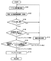
図3を参照して、本実施の形態に係る制御装置であるECU1000のECT_ECU1020で実行されるプログラムの制御構造について説明する。
With reference to FIG. 3, a control structure of a program executed by
ステップ(以下、ステップをSと略して記載する)100にて、ECT_ECU1020は、アクセル操作量を検知する。このとき、ECT_ECU1020は、エンジンECU1010を経由してアクセル開度センサが検知したアクセル開度信号に基づいて、アクセル操作量を検知する。
In step (hereinafter abbreviated as S) 100,
S102にて、ECT_ECU1020は、車速(出力軸回転数換算)を検知する。このとき、ECT_ECU1020は、自動変速機300の出力軸回転数センサが検知した出力軸回転数信号に基づいて、車速を検知する。
In S102,
S104にて、ECT_ECU1020は、アクセル戻し操作を検知したか否かを判断する。この判断は、検知したアクセル操作量に基づいて行なわれる。アクセル戻し操作を検知すると(S104にてYES)、処理はS106へ移される。もしそうでないと(S104にてNO)、処理はS100へ戻される。
In S104,
S106にて、ECT_ECU1020は、変速線図(変速マップ)に基づいて、アップシフト判定がされたか否かを判断する。この判断は、変速マップと、車速およびアクセル開度に基づくスロットル開度とに基づいて、アップシフト変速線を交差したか否かにより行なわれる。アップシフト判定されると(S106にてYES)、処理はS108へ移される。もしそうでないと(S106にてNO)、処理はS100へ戻される。
At S106,
S108にて、ECT_ECU1020は、仮想必要駆動力が、アップシフト後の変速ギヤ段における限界駆動力以下であるか否かを判断する。仮想必要駆動力の算出方法については後述する。限界駆動力は、たとえば{エンジン駆動力(トルク)×動力伝達装置の減速比(自動変速機300のアップシフト後の変速ギヤ段における変速比、トルクコンバータ200のトルク比、差動装置のギヤ比等)×エンジン100から駆動輪までの動力伝達系の損失}により算出される。仮想必要駆動力≦アップシフト後の変速ギヤ段における限界駆動力であると(S108にてYES)、処理はS110へ移される。もしそうでないと(S108にてNO)、処理はS112へ移される。なお、アップシフト後の変速ギヤ段における限界駆動力は、以下の説明において、「限界駆動力」とのみ記載する場合がある。
In S108,
S110にて、ECT_ECU1020は、アップシフト出力を自動変速機300に出力し、アップシフトが行なわれる。
At S110,
S112にて、ECT_ECU1020は、減速力補正処理を行なう。この処理は、自動変速機300の変速ギヤ段により被駆動力が異なるため、同じ車速で同じアクセル操作を行なっても、仮想必要駆動力によっては変速ギヤ段が異なる場合(アップシフトが許可される場合と禁止される場合)がある。このため、運転者がエンジンブレーキの効き具合に違和感を感じる場合がある。それを防止するために、アップシフト禁止の場合には(S108にてYES)、エンジン100のアイドル回転数を高めに制御して(変速ギヤ段がアップシフトされず同じままであるので、エンジントルクを高くして)、被駆動力(減速力)が、変速ギヤ段がアップシフトされた場合と同様になるようにする。これにより、アップシフトの有無によらず同等の被駆動力(減速力)を発生させることができるようになる。具体的には、ECT_ECU1020は、エンジンECU1010に、アップシフトの有無によらず同等の被駆動力(減速力)を発生させるエンジントルクが発生するように指令値を出力する。
In S112,
図4を参照して、本実施の形態に係る制御装置であるECU1000のECT_ECU1020で実行される仮想必要駆動力算出プログラムの制御構造について説明する。この処理は、図3のS108において用いられる仮想必要駆動力を算出する処理である。
With reference to FIG. 4, the control structure of the virtual required driving force calculation program executed by
S150にて、ECT_ECU1020は、現時点から予め定められた時間前までにおけるアクセルオン時のアクセル操作量を検知する。この予め定められた時間は、同じ傾向の勾配やコーナが続いている時間になるような短い時間に設定される。
At S150,
S152にて、ECT_ECU1020は、アクセル操作量に基づいて、運転者が要求するであろうと仮想した仮想必要駆動力を算出する。この仮想必要駆動力は、次の再加速時を仮想して、運転者が要求したり必要としたりするであろう駆動力である。
In S152,
S154にて、ECT_ECU1020は、出力駆動力が仮想必要駆動力以上であるか否かを判断する。出力駆動力は、現在出力していると推定できる駆動力であって、エンジン推定トルクを、予め計測して設定しておいた実験値マップ(パラメータはエンジン回転数および吸入空気量)から引き当てて、このエンジン推定トルクに基づいて、算出される。出力駆動力≧仮想必要駆動力であると(S154にてYES)、処理はS156へ移される。もしそうでないと(S154にてNO)、処理はS158へ移される。
In S154,
S156にて、ECT_ECU1020は、仮想必要駆動力=出力駆動力とする。これは、仮想必要駆動力は再加速時を仮想した駆動力であるので、現在出力している駆動力よりも小さくなることはない。このため、仮想必要駆動力が出力駆動力以下である場合には、仮想駆動力を出力駆動力とするものである。
In S156,
S158にて、ECT_ECU1020は、仮想必要駆動力を減少させる。このとき、ECT_ECU1020は、予め定められた割合の減少度合いで仮想必要駆動力を減少させたり、予め定められた量の減少度合いで仮想必要駆動力を減少させたり、滑らかに減少するような減少度合いで仮想必要駆動力を減少させさせたりする。この減少度合いは適宜設定されるものであるが、たとえば運転者の運転履歴を反映させて、減少度合いを予め定めておくと、運転者の運転要求が反映されるので好ましい。また、各変速ギヤ段ごとに減少度合いが設定される。
In S158,
以上のような構造およびフローチャートに基づく、本実施の形態に係る車両の制御装置であるECT_ECU1020を搭載した車両の動作について説明する。
An operation of a vehicle equipped with
たとえば、車両が登降坂路や平坦路を走行中において、前方車両との車間距離が縮まると、運転者がアクセルペダルを戻す(S104にてYES)。S100にて検知されたアクセル操作量に基づくスロットル開度およびS102にて検知した車速と、変速マップとに基づいて、アップシフト変速線と交差すると、アップシフト判定ありと判断される(S106にてYES)。 For example, when the vehicle is traveling on an uphill / downhill road or a flat road and the distance between the vehicle and the vehicle ahead decreases, the driver returns the accelerator pedal (YES in S104). Based on the throttle opening based on the accelerator operation amount detected in S100, the vehicle speed detected in S102, and the shift map, it is determined that there is an upshift determination when crossing the upshift line (in S106). YES).
仮想必要駆動力がアップシフト後の変速ギヤ段における限界駆動力以下であると、アップシフト変速しても十分な仮想必要駆動力を出力できると判断されて(S108にてYES)、アップシフト処理が行なわれる。 If the virtual required driving force is less than or equal to the limit driving force in the speed gear after the upshift, it is determined that sufficient virtual required driving force can be output even if the upshift is performed (YES in S108), and the upshift process is performed. Is done.
一方、仮想必要駆動力がアップシフト後の変速ギヤ段における限界駆動力よりも大きいと、アップシフト変速してしまうと十分に仮想必要駆動力を出力できないと判断されて(S108にてNO)、アップシフト禁止処理が行なわれる。アップシフト禁止処理が行なわれる場合には、エンジンブレーキの効き具合をアップシフトの有無によらないようにするため、減速力補正処理が実行される(S112)。 On the other hand, if the virtual required driving force is greater than the limit driving force in the shift gear after the upshift, it is determined that the virtual required driving force cannot be sufficiently output if the upshift is performed (NO in S108). Upshift prohibition processing is performed. When the upshift prohibition process is performed, the deceleration force correction process is executed in order to prevent the effectiveness of the engine brake from depending on the presence or absence of the upshift (S112).
このような動作において、仮想必要駆動力は、過去の運転履歴に基づいて、減少されて算出される。現時点から短い時間前までにおけるアクセルオン時のアクセル操作量が検知され(S150)、このアクセル操作量に基づいて、次の再加速時を仮想して仮想必要駆動力が算出される(S152)。仮想必要駆動力が出力駆動力よりも大きいと(S154にてNO)、仮想必要駆動力が過大過ぎるので仮想必要駆動力を減少させる(S158)。 In such an operation, the virtual required driving force is calculated by decreasing based on the past driving history. An accelerator operation amount when the accelerator is on from a current time to a short time before is detected (S150), and based on this accelerator operation amount, a virtual required driving force is calculated virtually at the next reacceleration time (S152). If the virtual necessary driving force is larger than the output driving force (NO in S154), the virtual necessary driving force is excessively large and the virtual necessary driving force is decreased (S158).
このとき、アクセルペダルを戻す操作が行なわれたときにおいては、たとえば、アクセル操作の変化に対する仮想必要駆動力の減少が緩やかになるように、仮想必要駆動力が算出される(S158)。アップシフト後の最大駆動力が、算出された仮想必要駆動力より大きい場合にアップシフトが許可され(S108にてYES)、ECT_ECU1020により自動変速機300がアップシフトされる(S110)。
At this time, when the operation of returning the accelerator pedal is performed, for example, the virtual required driving force is calculated so that the decrease in the virtual required driving force with respect to the change in the accelerator operation becomes gentle (S158). When the maximum driving force after the upshift is larger than the calculated virtual required driving force, the upshift is permitted (YES in S108), and
このようにすると、アップシフトされた後に(すなわち、要求される駆動力が、短時間の間であってもアップシフト後の変速ギヤ段による最大駆動力を下回る大きさまで低下したと判断された後に)、最大駆動力を上回る大きさまで増加すると、アップシフトした後にすぐにダウンシフトが発生してしまうことを回避できる。 In this way, after the upshift is performed (that is, after it is determined that the required driving force has decreased to a level below the maximum driving force by the transmission gear stage after the upshift even for a short period of time. ), Increasing to a magnitude exceeding the maximum driving force can prevent a downshift from occurring immediately after an upshift.
以上のように、図5に示すように、運転者によりアクセルペダルを戻す操作が行なわれたときにおいては、アクセル操作の変化に対する仮想必要駆動力の減少が緩やかになるように、仮想必要駆動力が算出される。このため、アクセル開度の減少に対して仮想必要駆動力はあまり減少しない(図5の一点鎖線を参照)。したがって、仮想必要駆動力が、アップシフト後の変速ギヤ段による最大駆動力を下回りにくくなる(アップシフト禁止側になりやすくなる)。そのため、アップシフトの許可が判断されるまでにタイムラグが発生し(一点鎖線で表わされる仮想必要駆動力がアップシフト後の変速ギヤ段における限界駆動力を下回るまでの時間が長引いて)、そのタイムラグに相当する時間の間に、アクセル開度がアップシフトを禁止する程度に変化すると(再加速のためのアクセルペダルが踏まれると)、アップシフトが発生しない。その結果、短時間の間にアクセル開度が減少した後に、アクセル開度が増加することに起因するアップシフトとダウンシフトの連続発生(シフトハンチング)を的確に防止することができる。 As described above, as shown in FIG. 5, when the driver performs an operation of returning the accelerator pedal, the virtual required driving force is reduced so that the decrease in the virtual required driving force with respect to the change in the accelerator operation becomes moderate. Is calculated. For this reason, the virtual required driving force does not decrease so much with respect to the decrease in the accelerator opening (see the one-dot chain line in FIG. 5). Therefore, the virtual required driving force is less likely to fall below the maximum driving force due to the transmission gear stage after the upshift (it is likely to be on the upshift prohibited side). For this reason, a time lag occurs until permission for upshifting is determined (the time required until the virtual required driving force indicated by the alternate long and short dash line falls below the limit driving force in the shift gear stage after the upshift is prolonged). If the accelerator opening changes to a level that prohibits upshifting during a time corresponding to (when the accelerator pedal for reacceleration is depressed), upshifting does not occur. As a result, after the accelerator opening decreases in a short period of time, it is possible to accurately prevent the occurrence of continuous upshifts and downshifts (shift hunting) due to the increase in accelerator opening.
<第2の実施の形態>
本実施の形態に係る制御装置を含む車両のパワートレーンについて説明する。本実施の形態に係る車両の制御ブロック図は、第1の実施の形態における制御ブロック図(図1)と同じである。本実施の形態においては、前述の実施の形態におけるECT_ECU1020で実行されるプログラムに加えて、別の仮想必要駆動力を減少させるプログラムを実行する。したがって、以下においては、このプログラムの制御構造についてのみ説明し、ハードウェア構成についての説明は繰返さない。
<Second Embodiment>
A vehicle power train including the control device according to the present embodiment will be described. The control block diagram of the vehicle according to the present embodiment is the same as the control block diagram (FIG. 1) in the first embodiment. In the present embodiment, in addition to the program executed by
図6を参照して、本実施の形態に係る制御装置であるECU1000のECT_ECU1020で実行される仮想必要駆動力減少処理プログラムの制御構造について説明する。
With reference to FIG. 6, the control structure of the virtual required driving force reduction processing program executed by
S200にて、ECT_ECU1020は、過去のアップシフト判定履歴を読出す。このとき、アップシフト判定されたときにメモリに記憶された、アップシフトのタイミング、限界駆動力、仮想必要駆動力が読み出される。
At S200,
S202にて、ECT_ECU1020は、仮想必要駆動力に基づくアップシフト判定前に、限界駆動力≧仮想必要駆動力が成立したか否かを判断する。限界駆動力≧仮想必要駆動力が成立すると(S202にてYES)、処理はS206へ移される。もしそうでないと(S202にてNO)、処理はS204へ移される。
In S202,
S204にて、ECT_ECU1020は、前回の限界駆動力≧仮想必要駆動力の成立から後で、仮想必要駆動力によるアップシフト判定までの間に限界駆動力≧仮想必要駆動力が成立していない否かを判断する。このような時間の間に、限界駆動力≧仮想必要駆動力が成立していないと(S204にてYES)、処理はS208へ移される。もしそうでないと(S204にてNO)、処理はS210へ移される。
In S204,
S206にて、ECT_ECU1020は、仮想必要駆動力の減少度合いを減らして、仮想必要駆動力を減少しにくくさせて仮想必要駆動力を減少させる。これは、仮想必要駆動力はより緩やかに小さくなる傾向である。
In S206,
S208にて、ECT_ECU1020は、仮想必要駆動力の減少度合いを増やして、
仮想必要駆動力を減少しやすくさせて仮想必要駆動力を減少させる。これは、仮想必要駆動力はより早く小さくなる傾向である。
In S208, the
The required virtual driving force is reduced by making it easier to reduce the required virtual driving force. This is a tendency that the virtual required driving force becomes smaller earlier.
S210にて、ECT_ECU1020は、仮想必要駆動力の減少度合いを変化させないで、仮想必要駆動力を減少させる。
In S210,
以上のような構造およびフローチャートに基づく、本実施の形態に係る車両の制御装置であるECT_ECU1020を搭載した車両における仮想必要駆動力を減少させる動作について説明する。なお、以下の動作の説明において前述の第1の実施の形態と同じ説明については、ここでは繰返さない。
An operation for reducing the virtual required driving force in a vehicle equipped with
仮想必要駆動力に基づくアップシフト判定前に、限界駆動力≧仮想必要駆動力が成立すると(S202にてYES)、仮想必要駆動力が早く減少しすぎているので、仮想必要駆動力の減少度合いを減らす(S206)。これにより、仮想必要駆動力を減少しにくくさせて、仮想必要駆動力を早く減少しないようにさせる。これで、仮想必要駆動力はより緩やかに小さくなる傾向になる。 If limit driving force ≧ virtual required driving force is satisfied before the upshift determination based on the virtual required driving force (YES in S202), the virtual required driving force has decreased too quickly, and thus the degree of decrease in virtual required driving force (S206). This makes it difficult to reduce the virtual required driving force and prevents the virtual required driving force from being reduced quickly. As a result, the virtual required driving force tends to decrease more gradually.
仮想必要駆動力に基づくアップシフト判定前に、限界駆動力≧仮想必要駆動力が成立しない場合であって(S202にてNO)、かつ前回の限界駆動力≧仮想必要駆動力の成立から後で、仮想必要駆動力によるアップシフト判定までの間に(図7の区間(A))、限界駆動力≧仮想必要駆動力が成立していないと(S204にてYES)、仮想必要駆動力の減少が遅いので、仮想必要駆動力の減少度合いを増やす(S208)。これにより、仮想必要駆動力を早く減少しやすくさせて、仮想必要駆動力が緩やかに減少しないようにさせる。これで、仮想必要駆動力はより早く小さくなる傾向になる。 Before the upshift determination based on the virtual required drive force, the limit drive force ≧ virtual required drive force is not established (NO in S202), and after the previous limit drive force ≧ virtual required drive force is established. If the limit drive force ≧ virtual required drive force is not established (YES in S204) until the upshift determination by the virtual required drive force (section (A) in FIG. 7), the virtual required drive force is reduced. Therefore, the degree of decrease in the virtual required driving force is increased (S208). As a result, the virtual required driving force is easily reduced quickly, and the virtual required driving force is not gradually reduced. As a result, the virtual required driving force tends to decrease earlier.
以上のようにして、過去のアップシフトの判定履歴に基づいて、仮想必要駆動力の減少度合いを変更することができるので、運転者の過去の運転履歴を反映させてアップシフト禁止判断を行なうことができる。 As described above, since the degree of decrease in the virtual required driving force can be changed based on the past upshift determination history, the upshift prohibition determination is performed by reflecting the past driving history of the driver. Can do.
<第3の実施の形態>
本実施の形態に係る制御装置を含む車両のパワートレーンについて説明する。本実施の形態に係る車両の制御ブロック図は、第1の実施の形態における制御ブロック図(図1)と同じである。本実施の形態においては、前述の第1の実施の形態におけるECT_ECU1020で実行されるプログラムに加えて、第2の実施の形態とは異なる仮想必要駆動力を減少させるプログラムを実行する。したがって、以下においては、このプログラムの制御構造についてのみ説明し、ハードウェア構成についての説明は繰返さない。
<Third Embodiment>
A vehicle power train including the control device according to the present embodiment will be described. The control block diagram of the vehicle according to the present embodiment is the same as the control block diagram (FIG. 1) in the first embodiment. In the present embodiment, in addition to the program executed by
図8を参照して、本実施の形態に係る制御装置であるECU1000のECT_ECU1020で実行される仮想必要駆動力減少処理プログラムの制御構造について説明する。なお、図8に示すフローチャートにおいて、図6と同じ処理については同じステップ番号を付してある。それらの処理も同じである。したがってそれらについての詳細な説明はここでは繰返さない。
With reference to FIG. 8, a control structure of a virtual required driving force reduction process program executed by
S300にて、ECT_ECU1020は、アップシフトタイミングを検知する。S302にて、ECT_ECU1020は、アクセル操作量を検知する。S304にて、ECT_ECU1020は、アクセル操作の時間変化を算出する。
In S300,
S306にて、ECT_ECU1020は、仮想必要駆動力に基づくアップシフト判定後、予め定められた時間内にアクセル踏み戻しダウンシフト判定されたか否かを判断する。仮想必要駆動力に基づくアップシフト判定後、予め定められた時間内にアクセル踏み戻しダウンシフト判定されると(S306にてYES)、処理はS206へ移される。もしそうでないと(S306にてNO)、処理はS308へ移される。
In S306,
S308にて、ECT_ECU1020は、アクセル戻し時のアクセル操作の時間変化が予め定められたしきい値よりも小さい(アクセルの戻し側の操作が緩やかである)か否かを判断する。アクセル戻し時のアクセル操作の時間変化が予め定められたしきい値よりも小さいと(S308にてYES)、処理はS208へ移される。もしそうでないと(S308にてNO)、処理はS210へ移される。
In S308,
以上のような構造およびフローチャートに基づく、本実施の形態に係る車両の制御装置であるECT_ECU1020を搭載した車両における仮想必要駆動力を減少させる動作について説明する。なお、以下の動作の説明において前述の第1の実施の形態または第2の実施の形態と同じ説明については、ここでは繰返さない。
An operation for reducing the virtual required driving force in a vehicle equipped with
仮想必要駆動力に基づくアップシフト判定後、予め定められた時間内に運転者がアクセルペダルを踏み込んでアクセル踏み戻しダウンシフトすると(S306にてYES)、仮想必要駆動力が早く減少しすぎてアップシフトを許可しているので、仮想必要駆動力の減少度合いを減らす(S206)。これにより、仮想必要駆動力を減少しにくくさせて、仮想必要駆動力を早く減少しないようにさせてアップシフトを禁止させる傾向を強める。これで、仮想必要駆動力はより緩やかに小さくなる傾向になり、アップシフトされにくくなり、運転者がアクセル踏み戻すこともなくなる。 After determining the upshift based on the virtual required driving force, if the driver depresses the accelerator pedal and downshifts the accelerator back within a predetermined time (YES in S306), the virtual required driving force decreases too quickly and increases. Since the shift is permitted, the degree of decrease in the virtual required driving force is reduced (S206). As a result, it is difficult to reduce the virtual necessary driving force, and the tendency to prohibit the upshift by preventing the virtual necessary driving force from being reduced quickly is strengthened. As a result, the virtual required driving force tends to be gradually reduced, and it is difficult for the vehicle to be upshifted, and the driver does not step back on the accelerator.
仮想必要駆動力に基づくアップシフト判定後、予め定められた時間内に運転者がアクセルペダルを踏み込んでアクセル踏み戻しダウンシフトされないで(S306にてNO)、かつアクセル戻し時のアクセル操作の時間変化が予め定められたしきい値よりも小さい(アクセルの戻し側の操作が緩やかである)と(S308にてYES)、仮想必要駆動力の減少が遅いので、仮想必要駆動力の減少度合いを増やす(S208)。これにより、仮想必要駆動力を早く減少しやすくさせて、仮想必要駆動力が緩やかに減少しないようにさせる。これで、仮想必要駆動力はより早く小さくなる傾向になる。 After the upshift determination based on the virtual required driving force, the driver does not depress the accelerator pedal to depress the accelerator pedal within a predetermined time (NO in S306), and the time change of the accelerator operation when the accelerator is returned Is smaller than a predetermined threshold value (operation on the return side of the accelerator is gentle) (YES in S308), the decrease in the virtual required driving force is slow, so the degree of decrease in the virtual required driving force is increased. (S208). As a result, the virtual required driving force is easily reduced quickly, and the virtual required driving force is not gradually reduced. As a result, the virtual required driving force tends to decrease earlier.
以上のようにして、過去の運転者のアクセル操作に基づいて、仮想必要駆動力の減少度合いを変更することができるので、運転者の過去の運転履歴を反映させてアップシフト禁止判断を行なうことができる。 As described above, the degree of decrease in the virtual required driving force can be changed based on the past driver's accelerator operation, so that the upshift prohibition determination is performed by reflecting the past driving history of the driver. Can do.
今回開示された実施の形態はすべての点で例示であって制限的なものではないと考えられるべきである。本発明の範囲は上記した説明ではなくて特許請求の範囲によって示され、特許請求の範囲と均等の意味および範囲内でのすべての変更が含まれることが意図される。 The embodiment disclosed this time should be considered as illustrative in all points and not restrictive. The scope of the present invention is defined by the terms of the claims, rather than the description above, and is intended to include any modifications within the scope and meaning equivalent to the terms of the claims.
100 エンジン、200 トルクコンバータ、300 自動変速機、1000 ECU、1010 エンジンECU、1020 ECT_ECU、2100 アクセル開度センサ。 100 engine, 200 torque converter, 300 automatic transmission, 1000 ECU, 1010 engine ECU, 1020 ECT_ECU, 2100 accelerator opening sensor.
Claims (7)
前記車両の運転者のアクセル操作を検知するための検知手段と、
前記アクセル操作に基づいて運転者が要求する仮想要求駆動力を算出するための算出手段と、
現在の変速段に対してアップシフトした場合の変速段で達成される最大駆動力を算出するための手段と、
前記仮想要求駆動力と前記最大駆動力とを比較して、前記最大駆動力が前記仮想要求駆動力より大きい場合にアップシフトを許可するように判断するための判断手段と、
前記判断手段の結果に基づいて、前記自動変速機を制御するための変速制御手段とを含み、
前記算出手段は、前記アクセル操作によるアクセル開度の減少側においては、アクセル操作の変化に対する仮想要求駆動力の減少が緩やかになるように、仮想要求駆動力を算出するための手段を含む、車両の制御装置。 A vehicle control device equipped with an automatic transmission,
Detection means for detecting the accelerator operation of the driver of the vehicle;
Calculation means for calculating a virtual required driving force requested by the driver based on the accelerator operation;
Means for calculating the maximum driving force achieved at the shift stage when upshifting with respect to the current shift stage;
A determination means for comparing the virtual required driving force with the maximum driving force and determining to permit an upshift when the maximum driving force is greater than the virtual required driving force;
Shift control means for controlling the automatic transmission based on the result of the determination means,
The calculation means includes a means for calculating a virtual required driving force so that a decrease in the virtual required driving force with respect to a change in the accelerator operation is moderated on a side where the accelerator opening is reduced by the accelerator operation. Control device.
Priority Applications (1)
| Application Number | Priority Date | Filing Date | Title |
|---|---|---|---|
| JP2003348993A JP2005114040A (en) | 2003-10-08 | 2003-10-08 | Vehicle control device |
Applications Claiming Priority (1)
| Application Number | Priority Date | Filing Date | Title |
|---|---|---|---|
| JP2003348993A JP2005114040A (en) | 2003-10-08 | 2003-10-08 | Vehicle control device |
Publications (1)
| Publication Number | Publication Date |
|---|---|
| JP2005114040A true JP2005114040A (en) | 2005-04-28 |
Family
ID=34540980
Family Applications (1)
| Application Number | Title | Priority Date | Filing Date |
|---|---|---|---|
| JP2003348993A Withdrawn JP2005114040A (en) | 2003-10-08 | 2003-10-08 | Vehicle control device |
Country Status (1)
| Country | Link |
|---|---|
| JP (1) | JP2005114040A (en) |
Cited By (5)
| Publication number | Priority date | Publication date | Assignee | Title |
|---|---|---|---|---|
| JP2006336716A (en) * | 2005-05-31 | 2006-12-14 | Isuzu Motors Ltd | Automatic shift control device |
| JP2006342787A (en) * | 2005-05-10 | 2006-12-21 | Toyota Motor Corp | Control device for internal combustion engine system |
| JP2017075659A (en) * | 2015-10-15 | 2017-04-20 | トヨタ自動車株式会社 | Control device for automatic transmission |
| JP2017180626A (en) * | 2016-03-30 | 2017-10-05 | マツダ株式会社 | Control device of engine with turbo supercharger |
| JP2017180627A (en) * | 2016-03-30 | 2017-10-05 | マツダ株式会社 | Control device of engine with turbo supercharger |
-
2003
- 2003-10-08 JP JP2003348993A patent/JP2005114040A/en not_active Withdrawn
Cited By (5)
| Publication number | Priority date | Publication date | Assignee | Title |
|---|---|---|---|---|
| JP2006342787A (en) * | 2005-05-10 | 2006-12-21 | Toyota Motor Corp | Control device for internal combustion engine system |
| JP2006336716A (en) * | 2005-05-31 | 2006-12-14 | Isuzu Motors Ltd | Automatic shift control device |
| JP2017075659A (en) * | 2015-10-15 | 2017-04-20 | トヨタ自動車株式会社 | Control device for automatic transmission |
| JP2017180626A (en) * | 2016-03-30 | 2017-10-05 | マツダ株式会社 | Control device of engine with turbo supercharger |
| JP2017180627A (en) * | 2016-03-30 | 2017-10-05 | マツダ株式会社 | Control device of engine with turbo supercharger |
Similar Documents
| Publication | Publication Date | Title |
|---|---|---|
| JP4306713B2 (en) | VEHICLE CONTROL DEVICE, CONTROL METHOD, PROGRAM FOR IMPLEMENTING THE CONTROL METHOD BY COMPUTER AND RECORDING MEDIUM CONTAINING THE PROGRAM | |
| US7001307B2 (en) | Shift control apparatus for vehicular automatic transmission and method thereof | |
| JP4857518B2 (en) | Vehicle control device | |
| US7900533B2 (en) | Control device for automatic transmission | |
| KR101162440B1 (en) | Automatic transmission control apparatus, control method, and recording medium on which program for realizing that method is recorded | |
| JP4639834B2 (en) | Control device for automatic transmission | |
| JP4538306B2 (en) | Shift control method and system for automatic transmission for vehicle | |
| JP2005075179A (en) | Vehicle control device | |
| JP2005114040A (en) | Vehicle control device | |
| JP3492843B2 (en) | Automatic transmission for vehicles | |
| JP3912312B2 (en) | Shift control device for automatic transmission | |
| JP3436992B2 (en) | Transmission control device for automatic transmission | |
| JPH08159278A (en) | Gear shift control device for automatic transmission | |
| JP4129714B2 (en) | Shift control device for automatic transmission | |
| JP4211550B2 (en) | Control device for automatic transmission | |
| JP3102278B2 (en) | Control device for automatic transmission for vehicle on downhill road | |
| JP2958580B2 (en) | Shift control device for automatic transmission for vehicle | |
| JP3461673B2 (en) | Shift control device for automatic transmission for vehicle | |
| JP4196789B2 (en) | Control device for automatic transmission | |
| JP2005076782A (en) | Automatic transmission control device | |
| JPH1044833A (en) | Compound control device for prime mover and automatic transmission | |
| JP2005125931A (en) | Vehicle control device | |
| JP4600291B2 (en) | Vehicle driving force control device | |
| JPH09242869A (en) | Speed change control device for automatic transmission for vehicle | |
| JP2005076764A (en) | Vehicle control device |
Legal Events
| Date | Code | Title | Description |
|---|---|---|---|
| A300 | Withdrawal of application because of no request for examination |
Free format text: JAPANESE INTERMEDIATE CODE: A300 Effective date: 20070109 |