JP2005094198A - Antenna assembly - Google Patents
Antenna assembly Download PDFInfo
- Publication number
- JP2005094198A JP2005094198A JP2003322938A JP2003322938A JP2005094198A JP 2005094198 A JP2005094198 A JP 2005094198A JP 2003322938 A JP2003322938 A JP 2003322938A JP 2003322938 A JP2003322938 A JP 2003322938A JP 2005094198 A JP2005094198 A JP 2005094198A
- Authority
- JP
- Japan
- Prior art keywords
- radiating element
- bent portion
- bent
- ground plane
- antenna device
- Prior art date
- Legal status (The legal status is an assumption and is not a legal conclusion. Google has not performed a legal analysis and makes no representation as to the accuracy of the status listed.)
- Pending
Links
- 230000005540 biological transmission Effects 0.000 claims description 11
- 230000005855 radiation Effects 0.000 abstract description 13
- 230000008878 coupling Effects 0.000 description 11
- 238000010168 coupling process Methods 0.000 description 11
- 238000005859 coupling reaction Methods 0.000 description 11
- 238000004891 communication Methods 0.000 description 10
- 238000005452 bending Methods 0.000 description 6
- 230000010287 polarization Effects 0.000 description 4
- 238000005259 measurement Methods 0.000 description 3
- 239000004020 conductor Substances 0.000 description 2
- 230000001413 cellular effect Effects 0.000 description 1
- 238000010586 diagram Methods 0.000 description 1
- 230000005684 electric field Effects 0.000 description 1
- 238000005516 engineering process Methods 0.000 description 1
- 239000002184 metal Substances 0.000 description 1
- 238000010295 mobile communication Methods 0.000 description 1
- 230000001629 suppression Effects 0.000 description 1
Images


Classifications
-
- H—ELECTRICITY
- H01—ELECTRIC ELEMENTS
- H01Q—ANTENNAS, i.e. RADIO AERIALS
- H01Q5/00—Arrangements for simultaneous operation of antennas on two or more different wavebands, e.g. dual-band or multi-band arrangements
-
- H—ELECTRICITY
- H01—ELECTRIC ELEMENTS
- H01Q—ANTENNAS, i.e. RADIO AERIALS
- H01Q1/00—Details of, or arrangements associated with, antennas
- H01Q1/12—Supports; Mounting means
- H01Q1/22—Supports; Mounting means by structural association with other equipment or articles
- H01Q1/24—Supports; Mounting means by structural association with other equipment or articles with receiving set
- H01Q1/241—Supports; Mounting means by structural association with other equipment or articles with receiving set used in mobile communications, e.g. GSM
-
- H—ELECTRICITY
- H01—ELECTRIC ELEMENTS
- H01Q—ANTENNAS, i.e. RADIO AERIALS
- H01Q1/00—Details of, or arrangements associated with, antennas
- H01Q1/12—Supports; Mounting means
- H01Q1/22—Supports; Mounting means by structural association with other equipment or articles
- H01Q1/24—Supports; Mounting means by structural association with other equipment or articles with receiving set
-
- H—ELECTRICITY
- H01—ELECTRIC ELEMENTS
- H01Q—ANTENNAS, i.e. RADIO AERIALS
- H01Q21/00—Antenna arrays or systems
- H01Q21/30—Combinations of separate antenna units operating in different wavebands and connected to a common feeder system
-
- H—ELECTRICITY
- H01—ELECTRIC ELEMENTS
- H01Q—ANTENNAS, i.e. RADIO AERIALS
- H01Q5/00—Arrangements for simultaneous operation of antennas on two or more different wavebands, e.g. dual-band or multi-band arrangements
- H01Q5/30—Arrangements for providing operation on different wavebands
- H01Q5/378—Combination of fed elements with parasitic elements
-
- H—ELECTRICITY
- H01—ELECTRIC ELEMENTS
- H01Q—ANTENNAS, i.e. RADIO AERIALS
- H01Q7/00—Loop antennas with a substantially uniform current distribution around the loop and having a directional radiation pattern in a plane perpendicular to the plane of the loop
Landscapes
- Engineering & Computer Science (AREA)
- Computer Networks & Wireless Communication (AREA)
- Variable-Direction Aerials And Aerial Arrays (AREA)
- Waveguide Aerials (AREA)
Abstract
Description
本発明は、移動体通信機器などに用いられ、複数の放射素子が接地面に配設されて構成されているアンテナ装置に関する。 The present invention relates to an antenna device that is used in a mobile communication device or the like and is configured by arranging a plurality of radiating elements on a ground plane.
複数の放射素子が接地面に配設されて構成されているアンテナ装置として、第1の放射素子と第2の放射素子との各々が略平行な2辺を有するように折返し部が形成されると共に略平行な2辺が接地面に対して略平行となるように折曲げ部が形成され、それら第1の放射素子と第2の放射素子とが平行に隣接されて接地面に配設されたものがある(例えば特許文献1参照)。
しかしながら、上記した特許文献1に記載されているアンテナ装置では、第2の放射素子の全体が第1の放射素子の外側に配設される構成であるので、多周波共振を実現するためには、共振点分の放射素子の幅および放射素子間の間隔が必要となり、装置全体が大型化するという問題がある。
However, in the antenna device described in
本発明は、上記した事情に鑑みてなされたものであり、その目的は、装置全体が大型化することがなく、多周波共振を適切に実現することができるアンテナ装置を提供することにある。 The present invention has been made in view of the above circumstances, and an object of the present invention is to provide an antenna device that can appropriately realize multi-frequency resonance without increasing the size of the entire device.
請求項1に記載した発明によれば、第1の放射素子は、略平行な2辺を有するように折返し部が形成されて両端部が接地面に対して略垂直に配設されてなる伝送線路アンテナからなり、一端部が給電点として作用すると共に他端部が接地面に対して電気的に接続され、略平行な2辺が接地面に対して略平行となるように折曲げ部が形成されて構成されている。第2の放射素子は、略平行な2辺を有するように折返し部が形成されて両端部が接地面に対して略垂直に配設されてなる伝送線路アンテナからなり、一端部と他端部との双方が接地面に対して電気的に接続され、略平行な2辺が接地面に対して略平行となるように折曲げ部が形成されて構成されている。 According to the first aspect of the present invention, the first radiating element has a folded portion formed so as to have two substantially parallel sides, and both end portions are disposed substantially perpendicular to the ground plane. It consists of a line antenna, one end acts as a feeding point, the other end is electrically connected to the ground plane, and the bent portion is formed so that two substantially parallel sides are substantially parallel to the ground plane. Formed and configured. The second radiating element includes a transmission line antenna in which a folded portion is formed so as to have two substantially parallel sides and both end portions are disposed substantially perpendicular to the ground plane, and one end portion and the other end portion Are both electrically connected to the ground plane, and a bent portion is formed so that two substantially parallel sides are substantially parallel to the ground plane.
そして、第2の放射素子の少なくとも一部が第1の放射素子の内側に配設され、第1の放射素子の一端部から折曲げ部までの部分と第2の放射素子の一端部から折曲げ部までの部分とが所定間隔を存して略平行に配設されると共に、第1の放射素子の他端部から折曲げ部までの部分と第2の放射素子の他端部から折曲げ部までの部分とが所定間隔を存して略平行に配設されて構成されている。 At least a part of the second radiating element is disposed inside the first radiating element, and the first radiating element is bent from one end of the first radiating element to the bent portion and from one end of the second radiating element. The portion up to the bent portion is disposed substantially in parallel with a predetermined interval, and the portion from the other end portion of the first radiating element to the bent portion and the other end portion of the second radiating element are folded. A portion up to the bent portion is arranged substantially in parallel with a predetermined interval.
これにより、第2の放射素子の全体が第1の放射素子の外側に配設される従来のものとは異なって、第2の放射素子の少なくとも一部が第1の放射素子の内側に配設されているので、装置全体が大型化することを未然に回避することができる。また、第1の放射素子の一端部から折曲げ部までの部分と第2の放射素子の一端部から折曲げ部までの部分とが所定間隔を存して略平行に配設されると共に、第1の放射素子の他端部から折曲げ部までの部分と第2の放射素子の他端部から折曲げ部までの部分とが所定間隔を存して略平行に配設されているので、第1の放射素子の一端部から折曲げ部までの部分、つまり、接地面に対して垂直となっている磁界が強い部分と第2の放射素子の一端部から折曲げ部までの部分とが電磁結合すると共に、第1の放射素子の他端部から折曲げ部までの部分、つまり、接地面に対して垂直となっている磁界が強い部分と第2の放射素子の他端部から折曲げ部までの部分とが電磁結合することにより、第2の放射素子が第1の放射素子に対して共振するようになり、多周波共振(2周波共振)を適切に実現することができる。尚、この場合、第1の放射素子と第2の放射素子との各々は、その全長が各々の通信電波の波長の略1/2の長さに構成され、第2の放射素子は、第1の放射素子よりも全長が短く、第1の放射素子よりも高周波側の通信電波に対応するように構成されている。 Thus, unlike the conventional one in which the entire second radiating element is disposed outside the first radiating element, at least a part of the second radiating element is arranged inside the first radiating element. Therefore, it is possible to prevent the entire apparatus from becoming large. In addition, the portion from the one end portion of the first radiating element to the bent portion and the portion from the one end portion of the second radiating element to the bent portion are disposed substantially in parallel with a predetermined interval, Since the portion from the other end of the first radiating element to the bent portion and the portion from the other end of the second radiating element to the bent portion are disposed substantially parallel to each other with a predetermined distance therebetween. , A portion from one end of the first radiating element to the bent portion, that is, a portion having a strong magnetic field perpendicular to the ground plane, and a portion from the one end of the second radiating element to the bent portion, From the other end portion of the first radiating element to the bent portion, that is, the portion having a strong magnetic field perpendicular to the ground plane and the other end portion of the second radiating element. The second radiating element resonates with respect to the first radiating element due to electromagnetic coupling with the portion up to the bent portion. Uninari, multifrequency resonance (two-frequency resonance) can be properly realized. In this case, each of the first radiating element and the second radiating element is configured so that the total length thereof is approximately ½ of the wavelength of each communication radio wave. The overall length is shorter than that of the first radiating element, and is configured to correspond to communication radio waves on the higher frequency side than the first radiating element.
請求項2に記載した発明によれば、第1の放射素子の折曲げ部から折返し部に向かう方向と第2の放射素子の折曲げ部から折返し部に向かう方向とが同方向に構成されているので、第2の放射素子の全体を第1の放射素子の内側に配設することができ、装置全体を小型化することができる。 According to the second aspect of the present invention, the direction from the folded portion of the first radiating element toward the folded portion and the direction from the folded portion of the second radiating element toward the folded portion are configured in the same direction. Therefore, the entire second radiating element can be disposed inside the first radiating element, and the entire apparatus can be reduced in size.
請求項3に記載した発明によれば、第1の放射素子の折曲げ部から折返し部に向かう方向と第2の放射素子の折曲げ部から折返し部に向かう方向とが逆方向に構成されているので、第2の放射素子の一端部から折曲げ部までの部分で発生される磁界が第1の放射素子の一端部から折曲げ部までの部分で発生される磁界から受ける影響を小さくすることができると共に、第2の放射素子の他端部から折曲げ部までの部分で発生される磁界が第1の放射素子の他端部から折曲げ部までの部分で発生される磁界から受ける影響を小さくすることができ、つまり、第2の放射素子で発生される磁界が第1の放射素子で発生される磁界により抑制されてしまうことを未然に回避することができ、第1の放射素子と第2の放射素子とによる多周波共振をより適切に実現することができる。 According to the third aspect of the present invention, the direction from the bent portion of the first radiating element toward the folded portion and the direction from the folded portion of the second radiating element toward the folded portion are configured in opposite directions. Therefore, the influence of the magnetic field generated in the portion from the one end portion of the second radiating element to the bent portion is affected by the magnetic field generated in the portion from the one end portion of the first radiating element to the bent portion. The magnetic field generated in the portion from the other end of the second radiating element to the bent portion is received from the magnetic field generated in the portion from the other end of the first radiating element to the bent portion. The influence can be reduced, that is, it can be avoided that the magnetic field generated by the second radiating element is suppressed by the magnetic field generated by the first radiating element. Multi-frequency resonance between the element and the second radiating element It can be properly realized.
請求項4に記載した発明によれば、第1の放射素子の一端部から折曲げ部までの部分と第2の放射素子の一端部から折曲げ部までの部分との間の所定間隔と、第1の放射素子の他端部から折曲げ部までの部分と第2の放射素子の他端部から折曲げ部までの部分との間の所定間隔とが略同一に構成されているので、第1の放射素子の一端部から折曲げ部までの部分と第2の放射素子の一端部から折曲げ部までの部分との間で発生される電磁結合と、第1の放射素子の他端部から折曲げ部までの部分と第2の放射素子の他端部から折曲げ部までの部分との間で発生される電磁結合との間で対称性を持たせることができ、第1の放射素子と第2の放射素子とによる多周波共振をより適切に実現することができる。 According to the invention described in claim 4, a predetermined interval between a portion from one end of the first radiating element to the bent portion and a portion from the one end of the second radiating element to the bent portion; Since the predetermined distance between the portion from the other end of the first radiating element to the bent portion and the portion from the other end of the second radiating element to the bent portion is configured substantially the same, Electromagnetic coupling generated between a portion from one end of the first radiating element to the bent portion and a portion from the one end of the second radiating element to the bent portion, and the other end of the first radiating element Symmetry between the portion from the portion to the bent portion and the electromagnetic coupling generated between the portion from the other end of the second radiating element to the bent portion. Multi-frequency resonance by the radiating element and the second radiating element can be more appropriately realized.
請求項5に記載した発明によれば、第1の放射素子の一端部から折曲げ部までの部分と、第1の放射素子の他端部から折曲げ部までの部分と、第2の放射素子の一端部から折曲げ部までの部分と、第2の放射素子の他端部から折曲げ部までの部分とが略同一の高さに構成されているので、第1の放射素子と第2の放射素子とによる多周波共振の効率を最良にすることができる。 According to the fifth aspect of the present invention, a portion from one end of the first radiating element to the bent portion, a portion from the other end of the first radiating element to the bent portion, and the second radiating element. Since the part from the one end part of the element to the bent part and the part from the other end part of the second radiating element to the bent part are configured at substantially the same height, the first radiating element and the second radiating element The efficiency of multi-frequency resonance by the two radiating elements can be optimized.
請求項6に記載した発明によれば、第3の放射素子は、略平行な2辺を有するように折返し部が形成されて両端部が接地面に対して略垂直に配設されてなる伝送線路アンテナからなり、一端部と他端部との双方が接地面に対して電気的に接続され、略平行な2辺が接地面に対して略平行となるように折曲げ部が形成されて構成されている。 According to the sixth aspect of the present invention, the third radiating element is a transmission in which the folded portion is formed so as to have two substantially parallel sides, and both ends are disposed substantially perpendicular to the ground plane. It is composed of a line antenna, and one end and the other end are electrically connected to the ground plane, and a bent portion is formed so that two substantially parallel sides are substantially parallel to the ground plane. It is configured.
そして、第3の放射素子の少なくとも一部が第1の放射素子の内側に配設され、第2の放射素子の一端部から折曲げ部までの部分と第3の放射素子の一端部から折曲げ部までの部分とが所定間隔を存して略平行に配設されると共に、第2の放射素子の他端部から折曲げ部までの部分と第3の放射素子の他端部から折曲げ部までの部分とが所定間隔を存して略平行に配設されて構成されている。 At least a part of the third radiating element is disposed inside the first radiating element, and is folded from one end of the second radiating element to the bent portion and from one end of the third radiating element. The portion up to the bent portion is disposed substantially in parallel with a predetermined interval, and the portion from the other end of the second radiating element to the bent portion and the other end of the third radiating element are folded from the other end. A portion up to the bent portion is arranged substantially in parallel with a predetermined interval.
これにより、第2の放射素子が第1の放射素子に対して共振するのに加えて、第2の放射素子の一端部から折曲げ部までの部分と第3の放射素子の一端部から折曲げ部までの部分とが電磁結合すると共に、第2の放射素子の他端部から折曲げ部までの部分と第3の放射素子の他端部から折曲げ部までの部分とが電磁結合することにより、第3の放射素子が第2の放射素子に対して共振するようにもなり、3周波共振を適切に実現することができる。尚、この場合、第3の放射素子は、その全長が通信電波の波長の略1/2の長さに構成され、第2の放射素子よりも全長が短く、第2の放射素子よりも高周波側の通信電波に対応するように構成されている。 Thereby, in addition to the second radiating element resonating with respect to the first radiating element, the second radiating element is folded from one end portion to the bent portion and the third radiating element end portion. The part from the other end of the second radiating element to the bent part and the part from the other end to the bent part of the third radiating element are electromagnetically coupled to the part to the bent part. Accordingly, the third radiating element also resonates with the second radiating element, and three-frequency resonance can be appropriately realized. In this case, the entire length of the third radiating element is approximately ½ of the wavelength of the communication radio wave, the total length is shorter than that of the second radiating element, and the frequency is higher than that of the second radiating element. It is comprised so that it may respond to the communication wave of the side.
請求項7に記載した発明によれば、第1の放射素子は、略平行な2辺を有するように折返し部が形成されて両端部が接地面に対して略垂直に配設されてなる伝送線路アンテナからなり、一端部が給電点として作用すると共に他端部が接地面に対して電気的に接続され、略平行な2辺が接地面に対して略平行となるように折曲げ部が形成されて構成されている。第2の放射素子は、折曲げ部を有する逆Lアンテナからなり、一端部が接地面に対して電気的に接続されて構成されている。 According to the seventh aspect of the present invention, the first radiating element has a folded portion formed so as to have two substantially parallel sides, and both end portions are disposed substantially perpendicular to the ground plane. It consists of a line antenna, one end acts as a feeding point, the other end is electrically connected to the ground plane, and the bent portion is formed so that two substantially parallel sides are substantially parallel to the ground plane. Formed and configured. The second radiating element is composed of an inverted L antenna having a bent portion, and one end thereof is electrically connected to the ground plane.
そして、第2の放射素子の少なくとも一部が第1の放射素子の内側に配設され、第1の放射素子の一端部から折曲げ部までの部分および第1の放射素子の他端部から折曲げ部までの部分のうちのいずれかと第2の放射素子の一端部から折曲げ部までの部分とが所定間隔を存して略平行に配設されて構成されている。 Then, at least a part of the second radiating element is disposed inside the first radiating element, from a portion from one end of the first radiating element to the bent portion and from the other end of the first radiating element. Any one of the portions up to the bent portion and the portion from the one end portion of the second radiating element to the bent portion are arranged substantially in parallel with a predetermined interval.
これにより、この場合も、上記した請求項1に記載したものと同様にして、第2の放射素子の少なくとも一部が第1の放射素子の内側に配設されているので、装置全体が大型化することを未然に回避することができる。また、第1の放射素子の一端部から折曲げ部までの部分および第1の放射素子の他端部から折曲げ部までの部分のいずれかと第2の放射素子の一端部から折曲げ部までの部分とが所定間隔を存して略平行に配設されているので、第1の放射素子の一端部から折曲げ部までの部分および第1の放射素子の他端部から折曲げ部までの部分のうちのいずれか、つまり、接地面に対して垂直となっている磁界が強い部分と第2の放射素子の一端部から折曲げ部までの部分とが電磁結合することにより、第2の放射素子が第1の放射素子に対して共振するようになり、この場合も、上記した請求項1に記載したものと同様にして、多周波共振(2周波共振)を適切に実現することができる。尚、この場合、第1の放射素子は、その全長が通信電波の波長の略1/2の長さに構成され、第2の放射素子は、その全長が通信電波の波長の略1/4の長さに構成され、第1の放射素子よりも全長が短く、第1の放射素子よりも高周波側の通信電波に対応するように構成されている。 Accordingly, in this case as well, as in the above-described aspect of the present invention, at least a part of the second radiating element is disposed inside the first radiating element. Can be avoided in advance. Further, either one of the first radiating element from one end to the bent portion and the other end from the first radiating element to the bent portion and the second radiating element from one end to the bent portion Are disposed substantially in parallel with each other at a predetermined interval, so that the portion from one end of the first radiating element to the bent portion and the other end of the first radiating element to the bent portion Any one of the portions, that is, a portion having a strong magnetic field perpendicular to the ground plane and a portion from one end portion of the second radiating element to the bent portion are electromagnetically coupled to each other. In this case, the multi-frequency resonance (two-frequency resonance) can be appropriately realized in the same manner as described in the first aspect. Can do. In this case, the total length of the first radiating element is approximately ½ of the wavelength of the communication radio wave, and the second radiating element is approximately ¼ of the wavelength of the communication radio wave. The overall length is shorter than that of the first radiating element, and is configured to correspond to communication radio waves on the higher frequency side than the first radiating element.
請求項8に記載した発明によれば、第1の放射素子の折曲げ部から折返し部に向かう方向と第2の放射素子の折曲げ部から他端部に向かう方向とが同方向に構成されているので、上記した請求項2に記載したものと同様にして、第2の放射素子の全体を第1の放射素子の内側に配設することができ、装置全体を小型化することができる。 According to the eighth aspect of the invention, the direction from the bent portion of the first radiating element toward the folded portion and the direction from the bent portion of the second radiating element toward the other end are configured in the same direction. Therefore, in the same manner as described in the second aspect, the entire second radiating element can be disposed inside the first radiating element, and the entire apparatus can be reduced in size. .
請求項9に記載した発明によれば、第1の放射素子の折曲げ部から折返し部に向かう方向と第2の放射素子の折曲げ部から他端部に向かう方向とが逆方向に構成されているので、第2の放射素子の一端部から折曲げ部までの部分で発生される磁界が第1の放射素子の一端部から折曲げ部までの部分および他端部から折曲げ部までの部分のうちのいずれかで発生される磁界から受ける影響を小さくすることができ、上記した請求項3に記載したものと同様にして、第2の放射素子で発生される磁界が第1の放射素子で発生される磁界により抑制されてしまうことを未然に回避することができ、第1の放射素子と第2の放射素子とによる多周波共振をより適切に実現することができる。 According to the ninth aspect of the present invention, the direction from the bent portion of the first radiating element toward the folded portion and the direction from the bent portion of the second radiating element toward the other end are configured in opposite directions. Therefore, the magnetic field generated in the portion from the one end portion of the second radiating element to the bent portion is the portion from the one end portion of the first radiating element to the bent portion and the portion from the other end portion to the bent portion. The influence from the magnetic field generated in any one of the portions can be reduced, and the magnetic field generated in the second radiating element is the first radiation in the same manner as described in the third aspect. Suppression by the magnetic field generated by the element can be avoided in advance, and multifrequency resonance by the first radiating element and the second radiating element can be realized more appropriately.
請求項10に記載した発明によれば、第1の放射素子の一端部から折曲げ部までの部分と、第1の放射素子の他端部から折曲げ部までの部分と、第2の放射素子の一端部から折曲げ部までの部分とが略同一の高さに構成されているので、上記した請求項5に記載したものと同様にして、第1の放射素子と第2の放射素子とによる多周波共振の効率を最良にすることができる。
According to the tenth aspect of the present invention, a portion from one end of the first radiating element to the bent portion, a portion from the other end of the first radiating element to the bent portion, and the second radiating element. Since the part from the one end part of the element to the bent part is formed at substantially the same height, the first radiating element and the second radiating element are the same as those described in
請求項11に記載した発明によれば、第3の放射素子は、折曲げ部を有する逆Lアンテナからなり、一端部が接地面に対して電気的に接続されて構成されている。そして、第2の放射素子の一端部から折曲げ部までの部分と第3の放射素子の一端部から折曲げ部までの部分とが所定間隔を存して略平行に配設されて構成されている。 According to the eleventh aspect of the present invention, the third radiating element is formed of an inverted L antenna having a bent portion, and one end thereof is electrically connected to the ground plane. And the part from the one end part of the second radiating element to the bent part and the part from the one end part of the third radiating element to the bent part are arranged substantially in parallel with a predetermined interval. ing.
これにより、第2の放射素子が第1の放射素子に対して共振するのに加えて、第2の放射素子の一端部から折曲げ部までの部分と第3の放射素子の一端部から折曲げ部までの部分とが電磁結合することにより、上記した請求項6に記載したものと同様にして、第3の放射素子が第2の放射素子に対して共振するようにもなり、3周波共振を適切に実現することができる。尚、この場合、第3の放射素子は、その全長が通信電波の波長の略1/4の長さに構成され、第2の放射素子よりも全長が短く、第2の放射素子よりも高周波側の通信電波に対応するように構成されている。 Thereby, in addition to the second radiating element resonating with respect to the first radiating element, the second radiating element is folded from one end portion to the bent portion and the third radiating element end portion. By electromagnetically coupling the portion up to the bent portion, the third radiating element resonates with respect to the second radiating element in the same manner as described in the sixth aspect, and the three frequencies Resonance can be appropriately realized. In this case, the entire length of the third radiating element is approximately ¼ of the wavelength of the communication radio wave, the total length is shorter than that of the second radiating element, and the frequency is higher than that of the second radiating element. It is comprised so that it may respond to the communication wave of the side.
請求項12に記載した発明によれば、第1の放射素子に給電するための給電ケーブルが接地面にあって少なくとも第1の放射素子および第2の放射素子が配設されている側と同一の側に配設されて構成されているので、装置全体の高さ方向の寸法を小さくすることでき、装置全体をより小型化することができる。 According to the twelfth aspect of the present invention, the power supply cable for supplying power to the first radiating element is on the ground plane, and at least the same side as the side on which the first radiating element and the second radiating element are disposed. Therefore, the height of the entire apparatus can be reduced, and the entire apparatus can be further reduced in size.
請求項13に記載した発明によれば、給電ケーブルが少なくとも第1の放射素子と接地面との間に形成される空間および第2の放射素子と接地面との間に形成される空間を回避して配設されて構成されているので、第1の放射素子の性能や第2の放射素子の性能が給電ケーブルの影響を受けて劣悪になることを未然に回避することができ、適切な性能を確保することができる。 According to the thirteenth aspect of the present invention, at least a space where the feed cable is formed between the first radiating element and the ground plane and a space formed between the second radiating element and the ground plane are avoided. Therefore, it is possible to prevent the performance of the first radiating element and the performance of the second radiating element from being deteriorated due to the influence of the power feeding cable. Performance can be ensured.
(第1の実施形態)
以下、本発明の第1の実施形態について、図1を参照して説明する。図1において、アンテナ装置1は、接地面2と、第1の放射素子3と、第2の放射素子4とを備えて構成されている。接地面2は、第1の放射素子3および第2の放射素子4よりも十分に大きなサイズを有する金属板から構成されている。
(First embodiment)
Hereinafter, a first embodiment of the present invention will be described with reference to FIG. In FIG. 1, the
第1の放射素子3は、略平行な2辺3a,3bを有するように折返し部3cが形成されて両端部3d,3eが接地面2の表面2a側(図1中、上面側)に対して略垂直に配設されてなる伝送線路アンテナからなり、一端部3dが給電点として作用すると共に他端部3eが接地面2に対して電気的に接続され、略平行な2辺3a,3bが接地面2に対して略平行となるように折曲げ部3f,3gが形成されて構成されている。
The
この第1の放射素子3は、その全長(一端部3dから他端部3eまでの長さ)が例えば「800MHz」帯域の電波の波長に「1/2」を乗じた長さに構成されている。また、この第1の放射素子3は、折曲げ部3f,3gにより折曲げられていることにより、低背構造を実現している。
The
第2の放射素子4は、略平行な2辺4a,4bを有するように折返し部4cが形成されて両端部4d,4eが接地面2の表面2a側に対して略垂直に配設されてなる伝送線路アンテナからなり、一端部4dと他端部4eとの双方が接地面2に対して電気的に接続され、略平行な2辺4a,4bが接地面2に対して略平行となるように折曲げ部4f,4gが形成されて構成されている。
The second radiating element 4 has a folded
この第2の放射素子4は、その全長(一端部4dから他端部4eまでの長さ)が例えば「1.9GHz」帯域の電波の波長に「1/2」を乗じた長さに構成されている。また、この第2の放射素子4は、折曲げ部4f,4gにより折曲げられていることにより、第1の放射素子3と同様にして、低背構造を実現している。
The second radiating element 4 has a total length (length from one
ここで、第2の放射素子4は、その全体が第1の放射素子3の内側に配設されている。具体的に説明すると、第2の放射素子4は、その高さ(一端部4dから折曲げ部4fまでの長さおよび一端部4eから折曲げ部4gまでの長さ)が第1の放射素子3の高さ(一端部3dから折曲げ部3fまでの長さおよび一端部3eから折曲げ部3gまでの長さ)と略同一に構成され、その一端部4dと他端部4eとが第1の放射素子3の一端部3dと他端部3eとを結ぶ直線よりも第1の放射素子3の折返し部3c側に配設されていると共に、その折曲げ部4f,4gから折返し部4cに向かう方向が第1の放射素子3の折曲げ部3f,3gから折返し部3cに向かう方向と同方向に配設されている。
Here, the entirety of the second radiating element 4 is disposed inside the
また、第1の放射素子3の一端部3dから折曲げ部3fまでの部分と第2の放射素子4の一端部4dから折曲げ部4fまでの部分とは、所定間隔を存して略平行に配設されると共に、第1の放射素子3の他端部3eから折曲げ部3gまでの部分と第2の放射素子4の他端部4eから折曲げ部4gまでの部分とは、所定間隔を存して略平行に配設されており、両者の所定間隔は、略同一となっている。
In addition, the portion from the
第1の放射素子3の一端部3dは、接地面2から僅かな間隙を存して離れており、第1の放射素子3に給電するための同軸ケーブル5は、その内部導体5aが第1の放射素子3の一端部3dに電気的に接続されている。また、この同軸ケーブル5は、その外部導体5bが接地面2に電気的に接続され、第1の放射素子3と接地面2との間に形成される空間および第2の放射素子4と接地面2との間に形成される空間を回避するように引回されて接地面2の表面2a側に配設されている。
One
そして、このように構成されてなるアンテナ装置1は、同軸ケーブル5を通じてナビゲーション装置6に接続される構成では、ナビゲーション装置6の外部アンテナとして機能することが可能であり、また、同軸ケーブル5を通じて携帯電話機7に接続される構成では、携帯電話機7の外部アンテナとして機能することが可能であり、さらに、同軸ケーブル5を通じてナビゲーション装置や携帯電話機に内蔵されているRF回路8に接続される構成では、ナビゲーション装置や携帯電話機の内蔵アンテナ(内部アンテナ)として機能することが可能である。
The
次に、上記した構成の作用について説明する。上記したアンテナ装置1では、同軸ケーブル5を通じて第1の放射素子3に給電されると、第1の放射素子3の一端部3dから折曲げ部3fまでの部分と第2の放射素子4の一端部4dから折曲げ部4fまでの部分とが所定間隔を存して略平行に配設されると共に、第1の放射素子3の他端部3eから折曲げ部3gまでの部分と第2の放射素子4の他端部4eから折曲げ部4gまでの部分とが所定間隔を存して略平行に配設されているので、第1の放射素子3の一端部3dから折曲げ部3fまでの部分、つまり、接地面2に対して垂直となっている磁界が強い部分と第2の放射素子4の一端部4dから折曲げ部4fまでの部分とが電磁結合すると共に(図1中「P1」参照)、第1の放射素子3の他端部3eから折曲げ部3gまでの部分、つまり、接地面2に対して垂直となっている磁界が強い部分と第2の放射素子4の他端部4eから折曲げ部4gまでの部分とが電磁結合することにより(図1中「P2」参照)、第2の放射素子4が第1の放射素子3に対して共振するようになる。これにより、アンテナ装置1は、第1の放射素子3により「800MHz」帯域の電波を適切に放射・捕捉することができると共に、第2の放射素子4により「1.9GHz」帯域の電波をも適切に放射・捕捉することが可能となる。
Next, the operation of the above configuration will be described. In the
ところで、上記した構成において、第2の放射素子4は、その全体が第1の放射素子3の内側に配設されているのに限らず、その一部が第1の放射素子3の内側に配設されていても良い。具体的に説明すると、第2の放射素子4は、第1の放射素子3に対して適切に共振する範囲内であれば、その一端部4dと他端部4eとが第1の放射素子3の一端部3dと他端部3eとを結ぶ直線よりも第1の放射素子3の折返し部3cとは反対側に配設されていても良い。また、第2の放射素子4の高さが第1の放射素子3の高さよりも低く構成されていても良い。
By the way, in the above-described configuration, the second radiating element 4 is not limited to being entirely disposed inside the
さらに、第1の放射素子3の一端部3dから折曲げ部3fまでの部分と第2の放射素子4の一端部4dから折曲げ部4fまでの部分との間の所定間隔と、第1の放射素子3の他端部3eから折曲げ部3gまでの部分と第2の放射素子4の他端部4eから折曲げ部4gまでの部分との間の所定間隔とが互いに相違していても良い。尚、これらの所定間隔は、通信周波数や、第1の放射素子3の高さおよび第2の放射素子4の高さや、第2の放射素子4の第1の放射素子3に対する配置位置などが考慮されて決定されるものである。
Furthermore, a predetermined interval between the portion from the one
以上に説明したように第1の実施形態によれば、アンテナ装置1において、第2の放射素子4の全体が第1の放射素子3の内側に配設されるように構成したので、装置全体が大型化することを未然に回避することができる。また、第1の放射素子3の一端部3dから折曲げ部3fまでの部分と第2の放射素子4の一端部4dから折曲げ部4fまでの部分とが所定間隔を存して略平行に配設されると共に、第1の放射素子3の他端部3eから折曲げ部3gまでの部分と第2の放射素子4の他端部4eから折曲げ部4gまでの部分とが所定間隔を存して略平行に配設されるように構成したので、第1の放射素子3の一端部3dから折曲げ部3fまでの部分、つまり、接地面2に対して垂直となっている磁界が強い部分と第2の放射素子4の一端部4dから折曲げ部4fまでの部分とが電磁結合すると共に、第1の放射素子3の他端部3eから折曲げ部3gまでの部分、つまり、接地面2に対して垂直となっている磁界が強い部分と第2の放射素子4の他端部4eから折曲げ部4gまでの部分とが電磁結合することにより、第2の放射素子4が第1の放射素子3に対して共振するようになり、2周波共振を適切に実現することができる。
As described above, according to the first embodiment, in the
また、第1の放射素子3の一端部3dから折曲げ部3fまでの部分と第2の放射素子4の一端部4dから折曲げ部4fまでの部分との間の所定間隔と、第1の放射素子3の他端部3eから折曲げ部3gまでの部分と第2の放射素子4の他端部4eから折曲げ部4gまでの部分との間の所定間隔とが略同一となるように構成したので、第1の放射素子3の一端部3dから折曲げ部3fまでの部分と第2の放射素子4の一端部4dから折曲げ部4fまでの部分との間で発生される電磁結合と、第1の放射素子3の他端部3eから折曲げ部3gまでの部分と第2の放射素子4の他端部4eから折曲げ部4gまでの部分との間で発生される電磁結合との間で対称性を持たせることができ、第1の放射素子3と第2の放射素子4とによる2周波共振をより適切に実現することができる。
In addition, a predetermined interval between a portion from one
さらに、第1の放射素子3の高さと第2の放射素子4の高さとが略同一となるように構成したので、第1の放射素子3と第2の放射素子4とによる2周波共振の効率を最良にすることができる。
Further, since the height of the
(第2の実施形態)
次に、本発明の第2の実施形態について、図2を参照して説明する。尚、上記した第1の実施形態と同一部分については説明を省略し、異なる部分について説明する。上記した第1の実施形態では、第2の放射素子4の折曲げ部4f,4gから折返し部4cに向かう方向と第1の放射素子3の折曲げ部3f,3gから折返し部3cに向かう方向とが同方向となるように構成されているが、これに対して、この第2の実施形態では、第2の放射素子の折曲げ部から折返し部に向かう方向と第1の放射素子3の折曲げ部3f,3gから折返し部3cに向かう方向とが逆方向となるように構成されている。
(Second Embodiment)
Next, a second embodiment of the present invention will be described with reference to FIG. In addition, description is abbreviate | omitted about the same part as above-mentioned 1st Embodiment, and a different part is demonstrated. In the first embodiment described above, the direction from the
すなわち、図2に示すように、アンテナ装置11において、第2の放射素子12は、上記した第1の実施形態で説明した第2の放射素子4と同一形状に構成されており、その全体が第1の放射素子3の内側に配設されているのではなく、その一部が第1の放射素子3の内側に配設されている。具体的に説明すると、第2の放射素子12は、その高さ(一端部12dから折曲げ部12fまでの長さおよび一端部12eから折曲げ部12gまでの長さ)が第1の放射素子3の高さと略同一に構成され、その一端部12dと他端部12eとが第1の放射素子3の一端部3dと他端部3eとを結ぶ直線よりも第1の放射素子3の折返し部3c側に配設されているが、上記した第1の実施形態とは異なって、その折曲げ部12f,12gから折返し部12cに向かう方向が第1の放射素子3の折曲げ部3f,3gから折返し部3cに向かう方向と逆方向となるように配設されている。
That is, as shown in FIG. 2, in the
以上に説明したように第2の実施形態によれば、アンテナ装置11において、第2の放射素子12の一部が第1の放射素子3の内側に配設されるように構成したので、上記した第1の実施形態と同様にして、装置全体が大型化することを未然に回避することができる。また、第1の放射素子3の一端部3dから折曲げ部3fまでの部分と第2の放射素子12の一端部12dから折曲げ部12fまでの部分とが所定間隔を存して略平行に配設されると共に、第1の放射素子3の他端部3eから折曲げ部3gまでの部分と第2の放射素子12の他端部12eから折曲げ部12gまでの部分とが所定間隔を存して略平行に配設されるように構成したので、第1の放射素子3の一端部3dから折曲げ部3fまでの部分、つまり、接地面2に対して垂直となっている磁界が強い部分と第2の放射素子12の一端部12dから折曲げ部12fまでの部分とが電磁結合すると共に(図2中「P3」参照)、第1の放射素子3の他端部3eから折曲げ部3gまでの部分、つまり、接地面2に対して垂直となっている磁界が強い部分と第2の放射素子12の他端部12eから折曲げ部12gまでの部分とが電磁結合することにより(図2中「P4」参照)、第2の放射素子12が第1の放射素子3に対して共振するようになり、上記した第1の実施形態と同様にして、2周波共振を適切に実現することができる。
As described above, according to the second embodiment, the
しかも、この第2の実施形態では、上記した第1の実施形態とは異なって、第2の放射素子12の折曲げ部12f,12gから折返し部12cに向かう方向と第1の放射素子3の折曲げ部3f,3gから折返し部3cに向かう方向とが逆方向となるように構成したので、第2の放射素子12の一端部12dから折曲げ部12fまでの部分で発生される磁界が第1の放射素子3の一端部3dから折曲げ部3fまでの部分で発生される磁界から受ける影響を小さくすることができると共に、第2の放射素子12の他端部12eから折曲げ部12gまでの部分で発生される磁界が第1の放射素子3の他端部3eから折曲げ部3gまでの部分で発生される磁界から受ける影響を小さくすることができ、つまり、第2の放射素子12で発生される磁界が第1の放射素子3で発生される磁界により抑制されてしまうことを未然に回避することができ、第1の放射素子3と第2の放射素子12とによる2周波共振をより適切に実現することができる。
Moreover, in the second embodiment, unlike the first embodiment described above, the direction from the
(第3の実施形態)
次に、本発明の第3の実施形態について、図3ないし図5を参照して説明する。尚、上記した第2の実施形態と同一部分については説明を省略し、異なる部分について説明する。上記した第2の実施形態では、第1の放射素子3と第2の放射素子12との2つの放射素子が接地面2に配設されて構成されているが、これに対して、この第3の実施形態では、第1の放射素子3と第2の放射素子12と第3の放射素子との3つの放射素子が接地面2に配設されて構成されている。
(Third embodiment)
Next, a third embodiment of the present invention will be described with reference to FIGS. In addition, description is abbreviate | omitted about the same part as above-mentioned 2nd Embodiment, and a different part is demonstrated. In the second embodiment described above, the two radiating elements, the
すなわち、図3に示すように、アンテナ装置21において、第3の放射素子22は、略平行な2辺22a,22bを有するように折返し部22cが形成されて両端部22d,22eが接地面2の表面2a側に対して略垂直に配設されてなる伝送線路アンテナからなり、一端部22dと他端部22eとの双方が接地面2に対して電気的に接続され、略平行な2辺22a,22bが接地面2に対して略平行となるように折曲げ部22f,22gが形成されて構成されている。この第3の放射素子22は、その全長(一端部22dから他端部22eまでの長さ)が例えば「2.1GHz」帯域の電波の波長に「1/2」を乗じた長さに構成されている。
That is, as shown in FIG. 3, in the
ここで、第3の放射素子22は、その全体が第1の放射素子3の内側に配設されている。具体的に説明すると、第3の放射素子22は、その高さ(一端部22dから折曲げ部22fまでの長さおよび一端部22eから折曲げ部22gまでの長さ)が第1の放射素子3の高さおよび第2の放射素子12の高さと略同一に構成され、その一端部22dと他端部22eとが第2の放射素子12の一端部12dと他端部12eとを結ぶ直線よりも第1の放射素子3の折返し部3c側に配設されていると共に、その折曲げ部22f,22gから折返し部22cに向かう方向が第1の放射素子3の折曲げ部3f,3gから折返し部3cに向かう方向と同方向となるように且つ第2の放射素子12の折曲げ部12f,12gから折返し部12cに向かう方向と逆方向となるように配設されている。
Here, the entire
また、第2の放射素子12の一端部12dから折曲げ部12fまでの部分と第3の放射素子22の一端部22dから折曲げ部22fまでの部分とは、所定間隔を存して略平行に配設されると共に、第2の放射素子12の他端部12eから折曲げ部12gまでの部分と第3の放射素子22の他端部22eから折曲げ部22gまでの部分とは、所定間隔を存して略平行に配設されている。この場合も、両者の所定間隔は、略同一となっている。
Further, the portion from the one
この場合、上記したアンテナ装置31では、同軸ケーブル5を通じて第1の放射素子3に給電されると、第2の放射素子12が第1の放射素子3に対して共振するようになると共に、第2の放射素子12の一端部12dから折曲げ部12fまでの部分、つまり、接地面2に対して垂直となっている磁界が強い部分と第3の放射素子22の一端部22dから折曲げ部22fまでの部分とが電磁結合すると共に(図3中「P5」参照)、第2の放射素子12の他端部12eから折曲げ部12gまでの部分、つまり、接地面2に対して垂直となっている磁界が強い部分と第3の放射素子22の他端部22eから折曲げ部22gまでの部分とが電磁結合することにより(図3中「P6」参照)、第3の放射素子22が21の放射素子12に対して共振するようにもなる。これにより、アンテナ装置31は、第1の放射素子3により「800MHz」帯域の電波を適切に放射・捕捉することができると共に、第2の放射素子12により「1.9GHz」帯域の電波をも適切に放射・捕捉することができると共に、第3の放射素子22により「2.1GHz」帯域の電波をも適切に放射・捕捉することが可能となる。
In this case, in the
以上に説明したように第3の実施形態によれば、アンテナ装置21において、第2の放射素子12の一端部12dから折曲げ部12fまでの部分と第3の放射素子22の一端部22dから折曲げ部22fまでの部分とが所定間隔を存して略平行に配設されると共に、第2の放射素子12の他端部12eから折曲げ部12gまでの部分と第3の放射素子22の他端部22eから折曲げ部22gまでの部分とが所定間隔を存して略平行に配設されるように構成したので、第2の放射素子12が第1の放射素子3に対して共振するのに加えて、第2の放射素子12の一端部12dから折曲げ部12fまでの部分と第3の放射素子22の一端部22dから折曲げ部22fまでの部分とが電磁結合すると共に、第2の放射素子12の他端部12eから折曲げ部12gまでの部分と第3の放射素子22の他端部22eから折曲げ部22gまでの部分とが電磁結合することにより、第3の放射素子22が第2の放射素子12に対して共振するようにもなり、3周波共振を適切に実現することができる。
As described above, according to the third embodiment, in the
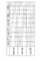
ところで、発明者らは、上記した第3の実施形態のように「800MHz」帯域の放射素子3、「1.9GHz」帯域の放射素子12および「2.1GHz」帯域の放射素子22の3つの放射素子が接地面2に配設されている構成で、各々の放射素子の配置方向(折曲げ部から折返し部に向かう方向)が各々の放射素子の性能に及ぼす影響について測定した。図4は、測定結果を表として示しており、図5は、図4に示されている表をグラフとして示している。
By the way, as described in the third embodiment, the inventors have three radiating
これら図4および図5から明らかなように、携帯電話用アンテナに適用した場合の実環境で強い電界成分である垂直偏波成分の平均利得を基準して判断すると、第1の放射素子3と第2の放射素子12とが逆方向の配置方向で配置され且つ第1の放射素子3と第3の放射素子22とが同方向の配置方向で配置されている構成(図3に示す配置方向の構成)では、第1の放射素子3の垂直偏波平均利得として「−2.3dBi」が得られており、第2の放射素子12の垂直偏波平均利得として「−3.1dBi」が得られており、第3の放射素子22の垂直偏波平均利得として「−4.1dBi」が得られており、全ての放射素子3,12,22において、ある程度の垂直偏波平均利得が得られている。
As apparent from FIGS. 4 and 5, the
(第4の実施形態)
次に、本発明の第4の実施形態について、図6を参照して説明する。尚、上記した第1の実施形態と同一部分については説明を省略し、異なる部分について説明する。上記した第1の実施形態では、第2の放射素子4が折返し部4cを有する伝送線路アンテナから構成されているが、これに対して、この第4の実施形態では、第2の放射素子が逆Lアンテナから構成されている。
(Fourth embodiment)
Next, a fourth embodiment of the present invention will be described with reference to FIG. In addition, description is abbreviate | omitted about the same part as above-mentioned 1st Embodiment, and a different part is demonstrated. In the first embodiment described above, the second radiating element 4 is composed of a transmission line antenna having the folded
すなわち、図6に示すように、アンテナ装置31において、第2の放射素子32は、上記した第1の実施形態で説明した第2の放射素子4とは異なった形状に構成されており、折曲げ部32aを有する逆Lアンテナからなり、一端部32bが接地面2に対して電気的に接続されて構成されている。この第2の放射素子32は、その全長(一端部32aから他端部32cまでの長さ)が例えば「1.9GHz」帯域の電波の波長に「1/4」を乗じた長さに構成されている。
That is, as shown in FIG. 6, in the
ここで、第2の放射素子32は、その全体が第1の放射素子3の内側に配設されている。具体的に説明すると、第2の放射素子32は、その高さ(一端部32bから折曲げ部32aまでの長さ)が第1の放射素子3の高さと略同一に構成され、その一端部32bが第1の放射素子3の一端部3dと他端部3eとを結ぶ直線よりも第1の放射素子3の折返し部3c側に配設されていると共に、その折曲げ部32aから他端部32cに向かう方向が第1の放射素子3の折曲げ部3f,3gから折返し部3cに向かう方向と同方向となるように配設されている。
Here, the entire
また、第1の放射素子3の一端部3dから折曲げ部3fまでの部分と第2の放射素子32の一端部32bから折曲げ部32aまでの部分とは、所定間隔を存して略平行に配設されている。
In addition, the portion from the
以上に説明したように第4の実施形態によれば、アンテナ装置31において、第2の放射素子32の全体が第1の放射素子3の内側に配設されるように構成したので、上記した第1の実施形態と同様にして、装置全体が大型化することを未然に回避することができる。また、第1の放射素子3の一端部3dから折曲げ部3fまでの部分と第2の放射素子32の一端部32bから折曲げ部32aまでの部分とが所定間隔を存して略平行に配設されるように構成したので、第1の放射素子3の一端部3dから折曲げ部3fまでの部分、つまり、接地面2に対して垂直となっている磁界が強い部分と第2の放射素子32の一端部32bから折曲げ部32aまでの部分とが電磁結合することにより(図6中「P7」参照)、第2の放射素子32が第1の放射素子3に対して共振するようになり、上記した第1の実施形態と同様にして、2周波共振を適切に実現することができる。
As described above, according to the fourth embodiment, the
(その他の実施形態)
本発明は、上記した実施形態にのみ限定されるものではなく、以下のように変形または拡張することができる。
(Other embodiments)
The present invention is not limited to the above-described embodiment, and can be modified or expanded as follows.
第1の実施形態に対して第3の放射素子を組合わせた構成であっても良く、つまり、3つの放射素子が接地面に配設される場合に、第1の放射素子3の折曲げ部3f,3gから折返し部3cに向かう方向と第2の放射素子4の折曲げ部4f,4gから折返し部4cに向かう方向と第3の放射素子の折曲げ部から折返し部に向かう方向とが全て同方向となる構成であっても良い。
The third radiating element may be combined with the first embodiment, that is, when the three radiating elements are disposed on the ground plane, the
第4の実施形態において、第1の放射素子3の一端部3dから折曲げ部3fまでの部分と第2の放射素子32の一端部32bから折曲げ部32aまでの部分との間で電磁結合が発生される構成に限らず、第2の放射素子32が第1の放射素子3の他端部3eから折曲げ部3gまでの部分に接近して配設されることにより、第1の放射素子3の他端部3eから折曲げ部3gまでの部分と第2の放射素子32の一端部32bから折曲げ部32aまでの部分との間で電磁結合が発生され、第2の放射素子32が第1の放射素子3に対して共振する構成であっても良い。
In the fourth embodiment, electromagnetic coupling between a portion from one
第1の放射素子が伝送線路アンテナからなり、且つ、第2の放射素子が逆Lアンテナからなる構成において、上記した第2の実施形態で説明した技術を適用する構成であっても良い。つまり、図7に示すように、アンテナ装置41において、第1の放射素子3の折曲げ部3f,3gから折返し部3cに向かう方向と第2の放射素子42の折曲げ部42aから他端部42cに向かう方向とが逆方向となる構成であっても良い。また、この場合も、第2の放射素子42が第1の放射素子3の他端部3eから折曲げ部3gまでの部分に接近して配設されることにより、第1の放射素子3の他端部3eから折曲げ部3gまでの部分と第2の放射素子42の一端部42bから折曲げ部42aまでの部分との間で電磁結合が発生され(図7中「P8」参照)、第2の放射素子42が第1の放射素子3に対して共振する構成であっても良い。
In a configuration in which the first radiating element is a transmission line antenna and the second radiating element is an inverted L antenna, the configuration described in the second embodiment may be applied. That is, as shown in FIG. 7, in the
第1の放射素子が伝送線路アンテナからなり、且つ、第2の放射素子が逆Lアンテナなり、且つ、第3の放射素子が逆Lアンテナからなる構成において、上記した第3の実施形態で説明した技術を適用する構成であっても良い。つまり、図8に示すように、アンテナ装置51において、第2の放射素子42が第1の放射素子3に対して共振すると共に、第2の放射素子42の一端部42bから折曲げ部42aまでの部分と第3の放射素子52の一端部52bから折曲げ部52aまでの部分とが所定間隔を存して略平行に配設され、第2の放射素子42の一端部42bから折曲げ部42aまでの部分と第3の放射素子52の一端部52bから折曲げ部52aまでの部分との間で電磁結合が発生され(図8中「P9」参照)、第3の放射素子52が第2の放射素子42に対して共振する構成であっても良い。
In the configuration in which the first radiating element is a transmission line antenna, the second radiating element is an inverted L antenna, and the third radiating element is an inverted L antenna, the third embodiment described above will be described. A configuration to which the technology is applied may be used. That is, as shown in FIG. 8, in the
「800MHz」や「1.9GHz」や「2.1GHz」帯域以外の帯域(例えば「1.5GHz」帯域)の電波に対応する構成であっても良い。
2周波共振や3周波共振を実現する構成に限らず、装置の大きさが許容される範囲内で、第2の放射素子と第3の放射素子との関係を繰返して構成することにより、3周波以上の多周波共振を実現する構成であっても良い。
A configuration corresponding to radio waves in a band other than the “800 MHz”, “1.9 GHz”, and “2.1 GHz” bands (for example, “1.5 GHz” band) may be used.
Not only the configuration that realizes the two-frequency resonance and the three-frequency resonance, but by repeatedly configuring the relationship between the second radiating element and the third radiating element within a range in which the size of the apparatus is allowed, 3 The structure which implement | achieves multifrequency resonance more than a frequency may be sufficient.
図面中、1はアンテナ装置、2は接地面、3は第1の放射素子、3a,3bは辺、3cは折返し部、3dは一端部、3eは他端部、3f,3gは折曲げ部、4は第2の放射素子、4a,4bは辺、4cは折返し部、4dは一端部、4eは他端部、4f,4gは折曲げ部、5は同軸ケーブル、11はアンテナ装置、12は第2の放射素子、12a,12bは辺、12cは折返し部、12dは一端部、12eは他端部、12f,12gは折曲げ部、21はアンテナ装置、22は第3の放射素子、22a,22bは辺、22cは折返し部、22dは一端部、22eは他端部、22f,22gは折曲げ部、31はアンテナ装置、32は第2の放射素子、32aは折曲げ部、32bは一端部、32cは他端部、41はアンテナ装置、42は第2の放射素子、42aは折曲げ部、42bは一端部、42cは他端部、51はアンテナ装置、52は第3の放射素子、52aは折曲げ部、52bは一端部、52cは他端部である。
In the drawings, 1 is an antenna device, 2 is a ground plane, 3 is a first radiating element, 3a and 3b are sides, 3c is a folded portion, 3d is one end, 3e is the other end, and 3f and 3g are bent portions. 4 is a second radiating element, 4a and 4b are sides, 4c is a folded portion, 4d is one end, 4e is the other end, 4f and 4g are folded portions, 5 is a coaxial cable, 11 is an antenna device, 12 Is a second radiating element, 12a and 12b are sides, 12c is a folded portion, 12d is one end, 12e is the other end, 12f and 12g are folded portions, 21 is an antenna device, 22 is a third radiating element, 22a and 22b are sides, 22c is a folded portion, 22d is one end, 22e is the other end, 22f and 22g are folded portions, 31 is an antenna device, 32 is a second radiating element, 32a is a folded portion, and 32b. Is one end, 32c is the other end, 41 is an antenna device, and 42 is a second radiation element. , 42a is bent portion, 42b at one end, 42c the other end, 51 an antenna device, 52 the third radiating element, 52a is bent portion, 52b at one end, 52c is the other end.
Claims (13)
略平行な2辺を有するように折返し部が形成されて両端部が前記接地面に対して略垂直に配設されてなる伝送線路アンテナからなり、一端部が給電点として作用すると共に他端部が前記接地面に対して電気的に接続され、略平行な2辺が前記接地面に対して略平行となるように折曲げ部が形成されてなる第1の放射素子と、
略平行な2辺を有するように折返し部が形成されて両端部が前記接地面に対して略垂直に配設されてなる伝送線路アンテナからなり、一端部と他端部との双方が前記接地面に対して電気的に接続され、略平行な2辺が前記接地面に対して略平行となるように折曲げ部が形成されてなる第2の放射素子とを備え、
前記第2の放射素子の少なくとも一部が前記第1の放射素子の内側に配設され、前記第1の放射素子の一端部から折曲げ部までの部分と前記第2の放射素子の一端部から折曲げ部までの部分とが所定間隔を存して略平行に配設されると共に、前記第1の放射素子の他端部から折曲げ部までの部分と前記第2の放射素子の他端部から折曲げ部までの部分とが所定間隔を存して略平行に配設されていることを特徴とするアンテナ装置。 A ground plane;
A folded portion is formed so as to have two substantially parallel sides, and both end portions are composed of a transmission line antenna disposed substantially perpendicular to the ground plane, and one end portion serves as a feeding point and the other end portion. Is electrically connected to the ground plane, and a first radiating element in which a bent portion is formed so that two substantially parallel sides are substantially parallel to the ground plane;
The transmission line antenna has a folded portion formed so as to have two substantially parallel sides and both ends are arranged substantially perpendicular to the ground plane, and both one end and the other end are connected to each other. A second radiating element that is electrically connected to the ground and has a bent portion formed such that two substantially parallel sides are substantially parallel to the ground plane;
At least a part of the second radiating element is disposed inside the first radiating element, and a portion from one end of the first radiating element to a bent portion and one end of the second radiating element. From the other end of the first radiating element to the bent part and the other part of the second radiating element. An antenna device characterized in that a portion from an end portion to a bent portion is disposed substantially in parallel with a predetermined interval.
前記第1の放射素子の折曲げ部から折返し部に向かう方向と前記第2の放射素子の折曲げ部から折返し部に向かう方向とが同方向に構成されていることを特徴とするアンテナ装置。 The antenna device according to claim 1, wherein
An antenna device, wherein a direction from the bent portion of the first radiating element toward the folded portion and a direction from the bent portion of the second radiating element toward the folded portion are configured in the same direction.
前記第1の放射素子の折曲げ部から折返し部に向かう方向と前記第2の放射素子の折曲げ部から折返し部に向かう方向とが逆方向に構成されていることを特徴とするアンテナ装置。 The antenna device according to claim 1, wherein
An antenna device, wherein a direction from the bent portion of the first radiating element toward the folded portion and a direction from the folded portion to the folded portion of the second radiating element are configured in opposite directions.
前記第1の放射素子の一端部から折曲げ部までの部分と前記第2の放射素子の一端部から折曲げ部までの部分との間の所定間隔と、前記第1の放射素子の他端部から折曲げ部までの部分と前記第2の放射素子の他端部から折曲げ部までの部分との間の所定間隔とが略同一に構成されていることを特徴とするアンテナ装置。 The antenna device according to any one of claims 1 to 3,
A predetermined distance between a portion from one end of the first radiating element to the bent portion and a portion from the one end of the second radiating element to the bent portion, and the other end of the first radiating element; An antenna device, wherein a predetermined distance between a portion from the first portion to the bent portion and a portion from the other end of the second radiating element to the bent portion is configured to be substantially the same.
前記第1の放射素子の一端部から折曲げ部までの部分と、前記第1の放射素子の他端部から折曲げ部までの部分と、前記第2の放射素子の一端部から折曲げ部までの部分と、前記第2の放射素子の他端部から折曲げ部までの部分とが略同一の高さに構成されていることを特徴とするアンテナ装置。 The antenna device according to any one of claims 1 to 4,
A portion from one end portion of the first radiating element to the bent portion, a portion from the other end portion of the first radiating element to the bent portion, and a bent portion from the one end portion of the second radiating element. And the portion from the other end of the second radiating element to the bent portion are configured to have substantially the same height.
略平行な2辺を有するように折返し部が形成されて両端部が前記接地面に対して略垂直に配設されてなる伝送線路アンテナからなり、一端部と他端部との双方が前記接地面に対して電気的に接続され、略平行な2辺が前記接地面に対して略平行となるように折曲げ部が形成されてなる第3の放射素子を備え、
前記第3の放射素子の少なくとも一部が前記第1の放射素子の内側に配設され、前記第2の放射素子の一端部から折曲げ部までの部分と前記第3の放射素子の一端部から折曲げ部までの部分とが所定間隔を存して略平行に配設されると共に、前記第2の放射素子の他端部から折曲げ部までの部分と前記第3の放射素子の他端部から折曲げ部までの部分とが所定間隔を存して略平行に配設されていることを特徴とするアンテナ装置。 The antenna device according to any one of claims 1 to 5,
The transmission line antenna has a folded portion formed so as to have two substantially parallel sides and both ends are arranged substantially perpendicular to the ground plane, and both one end and the other end are connected to each other. A third radiating element that is electrically connected to the ground and has a bent portion formed so that two substantially parallel sides are substantially parallel to the ground plane;
At least a part of the third radiating element is disposed inside the first radiating element, and a portion from one end of the second radiating element to a bent portion and one end of the third radiating element. From the other end of the second radiating element to the bent part and the other part of the third radiating element. An antenna device characterized in that a portion from an end portion to a bent portion is disposed substantially in parallel with a predetermined interval.
略平行な2辺を有するように折返し部が形成されて両端部が前記接地面に対して略垂直に配設されてなる伝送線路アンテナからなり、一端部が給電点として作用すると共に他端部が前記接地面に対して電気的に接続され、略平行な2辺が前記接地面に対して略平行となるように折曲げ部が形成されてなる第1の放射素子と、
折曲げ部を有する逆Lアンテナからなり、一端部が前記接地面に対して電気的に接続されてなる第2の放射素子とを備え、
前記第2の放射素子の少なくとも一部が前記第1の放射素子の内側に配設され、前記第1の放射素子の一端部から折曲げ部までの部分および前記第1の放射素子の他端部から折曲げ部までの部分のうちのいずれかと前記第2の放射素子の一端部から折曲げ部までの部分とが所定間隔を存して略平行に配設されていることを特徴とするアンテナ装置。 A ground plane;
A folded portion is formed so as to have two substantially parallel sides, and both end portions are composed of a transmission line antenna disposed substantially perpendicular to the ground plane, and one end portion serves as a feeding point and the other end portion. Is electrically connected to the ground plane, and a first radiating element in which a bent portion is formed so that two substantially parallel sides are substantially parallel to the ground plane;
A second radiating element comprising an inverted L antenna having a bent portion, one end of which is electrically connected to the ground plane;
At least a part of the second radiating element is disposed inside the first radiating element, a portion from one end of the first radiating element to a bent portion and the other end of the first radiating element Any one of the parts from the part to the bent part and the part from the one end part of the second radiating element to the bent part are arranged substantially in parallel with a predetermined interval. Antenna device.
前記第1の放射素子の折曲げ部から折返し部に向かう方向と前記第2の放射素子の折曲げ部から他端部に向かう方向とが同方向に構成されていることを特徴とするアンテナ装置。 The antenna device according to claim 7, wherein
The antenna device characterized in that the direction from the bent portion of the first radiating element toward the folded portion and the direction from the bent portion of the second radiating element toward the other end are configured in the same direction. .
前記第1の放射素子の折曲げ部から折返し部に向かう方向と前記第2の放射素子の折曲げ部から他端部に向かう方向とが逆方向に構成されていることを特徴とするアンテナ装置。 The antenna device according to claim 7, wherein
An antenna device characterized in that the direction from the bent portion of the first radiating element toward the folded portion and the direction from the bent portion of the second radiating element toward the other end are opposite to each other. .
前記第1の放射素子の一端部から折曲げ部までの部分と、前記第1の放射素子の他端部から折曲げ部までの部分と、前記第2の放射素子の一端部から折曲げ部までの部分とが略同一の高さに構成されていることを特徴とするアンテナ装置。 The antenna device according to any one of claims 7 to 9,
A portion from one end portion of the first radiating element to the bent portion, a portion from the other end portion of the first radiating element to the bent portion, and a bent portion from the one end portion of the second radiating element. The antenna device is characterized in that the portion up to is configured at substantially the same height.
折曲げ部を有する逆Lアンテナからなり、一端部が前記接地面に対して電気的に接続されてなる第3の放射素子を備え、
前記第2の放射素子の一端部から折曲げ部までの部分と前記第3の放射素子の一端部から折曲げ部までの部分とが所定間隔を存して略平行に配設されていることを特徴とするアンテナ装置。 The antenna device according to any one of claims 7 to 10,
A third radiating element comprising an inverted L antenna having a bent portion, one end of which is electrically connected to the ground plane;
The portion from the one end of the second radiating element to the bent portion and the portion from the one end to the bent portion of the third radiating element are disposed substantially in parallel with a predetermined interval. An antenna device characterized by the above.
前記第1の放射素子に給電するための給電ケーブルが前記接地面にあって少なくとも前記第1の放射素子および前記第2の放射素子が配設されている側と同一の側に配設されていることを特徴とするアンテナ装置。 The antenna device according to any one of claims 1 to 11,
A power supply cable for supplying power to the first radiating element is disposed on the ground plane, and is disposed at least on the same side as the side on which the first radiating element and the second radiating element are disposed. An antenna device comprising:
前記給電ケーブルが少なくとも前記第1の放射素子と前記接地面との間に形成されている空間および前記第2の放射素子と前記接地面との間に形成されている空間を回避して配設されていることを特徴とするアンテナ装置。
The antenna device according to claim 12, wherein
The feeding cable is disposed avoiding at least a space formed between the first radiating element and the ground plane and a space formed between the second radiating element and the ground plane. An antenna device characterized by being made.
Priority Applications (4)
| Application Number | Priority Date | Filing Date | Title |
|---|---|---|---|
| JP2003322938A JP2005094198A (en) | 2003-09-16 | 2003-09-16 | Antenna assembly |
| KR1020040070267A KR100599337B1 (en) | 2003-09-16 | 2004-09-03 | Antenna device |
| US10/936,001 US7030833B2 (en) | 2003-09-16 | 2004-09-08 | Antenna device |
| CNB200410079741XA CN100364173C (en) | 2003-09-16 | 2004-09-16 | Antenna device |
Applications Claiming Priority (1)
| Application Number | Priority Date | Filing Date | Title |
|---|---|---|---|
| JP2003322938A JP2005094198A (en) | 2003-09-16 | 2003-09-16 | Antenna assembly |
Publications (1)
| Publication Number | Publication Date |
|---|---|
| JP2005094198A true JP2005094198A (en) | 2005-04-07 |
Family
ID=34270011
Family Applications (1)
| Application Number | Title | Priority Date | Filing Date |
|---|---|---|---|
| JP2003322938A Pending JP2005094198A (en) | 2003-09-16 | 2003-09-16 | Antenna assembly |
Country Status (4)
| Country | Link |
|---|---|
| US (1) | US7030833B2 (en) |
| JP (1) | JP2005094198A (en) |
| KR (1) | KR100599337B1 (en) |
| CN (1) | CN100364173C (en) |
Cited By (6)
| Publication number | Priority date | Publication date | Assignee | Title |
|---|---|---|---|---|
| JP2007124016A (en) * | 2005-10-25 | 2007-05-17 | Denso Corp | Integrated antenna |
| JP2007181076A (en) * | 2005-12-28 | 2007-07-12 | Fujitsu Ltd | Antenna, method for adjusting resonance frequency thereof, and wireless communication apparatus |
| KR100880898B1 (en) | 2008-04-25 | 2009-01-30 | 주식회사 선우커뮤니케이션 | Dual Band Patch Antenna |
| JP2009033571A (en) * | 2007-07-27 | 2009-02-12 | Nippon Soken Inc | Integrated antenna |
| JP2011030196A (en) * | 2009-07-01 | 2011-02-10 | Nec Corp | Multi-band loop antenna |
| JP2019121826A (en) * | 2017-12-28 | 2019-07-22 | キヤノン株式会社 | antenna |
Families Citing this family (17)
| Publication number | Priority date | Publication date | Assignee | Title |
|---|---|---|---|---|
| US7308291B2 (en) * | 2004-12-15 | 2007-12-11 | Motorola Inc. | Antenna for sending and receiving signals in a plurality of frequency bands |
| US7265726B2 (en) * | 2005-09-26 | 2007-09-04 | Motorola, Inc. | Multi-band antenna |
| US7298339B1 (en) * | 2006-06-27 | 2007-11-20 | Nokia Corporation | Multiband multimode compact antenna system |
| US8738103B2 (en) | 2006-07-18 | 2014-05-27 | Fractus, S.A. | Multiple-body-configuration multimedia and smartphone multifunction wireless devices |
| CN101154760B (en) * | 2006-09-29 | 2012-05-23 | 富士康(昆山)电脑接插件有限公司 | Antenna assembly |
| KR100820374B1 (en) * | 2007-02-06 | 2008-04-08 | 한양대학교 산학협력단 | Wire Antennas for Next Generation Mobile Handset |
| JP4922003B2 (en) * | 2007-02-13 | 2012-04-25 | 株式会社東芝 | ANTENNA DEVICE AND RADIO DEVICE |
| CN101257143B (en) * | 2007-02-26 | 2012-01-11 | 连展科技电子(昆山)有限公司 | Back ring type coupled aerial |
| US7642971B2 (en) * | 2007-05-25 | 2010-01-05 | Sony Ericsson Mobile Communications Ab | Compact diversity antenna arrangement |
| CN101453052B (en) * | 2007-12-04 | 2012-09-26 | 启碁科技股份有限公司 | Antenna structure |
| CN102025027B (en) * | 2009-09-15 | 2014-12-17 | 光宝电子(广州)有限公司 | Dual-loop antenna and multi-frequency multi-antenna module |
| CN102386482B (en) * | 2010-09-06 | 2014-06-18 | 光宝电子(广州)有限公司 | Multi-loop antenna system and electronic device with same |
| CN102738565A (en) * | 2012-06-09 | 2012-10-17 | 陕西凌云电器集团有限公司 | Airborne navigation antenna |
| CN106159447B (en) * | 2015-04-14 | 2019-06-25 | 启碁科技股份有限公司 | Smart Antenna Module and Omnidirectional Antenna |
| TWI669723B (en) * | 2018-06-12 | 2019-08-21 | 岳林工業有限公司 | Transmission-signal cable and manufacturing method thereof |
| TWI717932B (en) * | 2019-12-10 | 2021-02-01 | 宏碁股份有限公司 | Mobile device and detachable antenna structure |
| CN115708256A (en) * | 2021-08-20 | 2023-02-21 | 荣耀终端有限公司 | Terminal monopole antenna of coupling feed |
Family Cites Families (10)
| Publication number | Priority date | Publication date | Assignee | Title |
|---|---|---|---|---|
| JPS639206A (en) | 1986-06-30 | 1988-01-14 | Yagi Antenna Co Ltd | Antenna system |
| US5583523A (en) * | 1992-01-06 | 1996-12-10 | C & K Systems, Incorporation | Planar microwave tranceiver employing shared-ground-plane antenna |
| US5847683A (en) * | 1996-10-28 | 1998-12-08 | Motorola, Inc. | Transmission line antenna and utility meter using same |
| JP2999754B1 (en) | 1998-08-25 | 2000-01-17 | 日本アンテナ株式会社 | Dual frequency inverted F-type antenna |
| AU778969B2 (en) * | 1999-11-03 | 2004-12-23 | Andrew Corporation | Folded dipole antenna |
| GB0030741D0 (en) * | 2000-12-16 | 2001-01-31 | Koninkl Philips Electronics Nv | Antenna arrangement |
| JP2002290138A (en) | 2001-03-26 | 2002-10-04 | Kyocera Corp | Antenna device |
| GB2381664B (en) * | 2001-10-12 | 2003-11-19 | Murata Manufacturing Co | Loop antenna, surface-mounted antenna and communication equipment having the same |
| JP2004129062A (en) | 2002-10-04 | 2004-04-22 | Sharp Corp | Frequency sharing antenna |
| JP2004201278A (en) | 2002-12-06 | 2004-07-15 | Sharp Corp | Pattern antenna |
-
2003
- 2003-09-16 JP JP2003322938A patent/JP2005094198A/en active Pending
-
2004
- 2004-09-03 KR KR1020040070267A patent/KR100599337B1/en not_active Expired - Fee Related
- 2004-09-08 US US10/936,001 patent/US7030833B2/en not_active Expired - Fee Related
- 2004-09-16 CN CNB200410079741XA patent/CN100364173C/en not_active Expired - Fee Related
Cited By (8)
| Publication number | Priority date | Publication date | Assignee | Title |
|---|---|---|---|---|
| JP2007124016A (en) * | 2005-10-25 | 2007-05-17 | Denso Corp | Integrated antenna |
| JP2007181076A (en) * | 2005-12-28 | 2007-07-12 | Fujitsu Ltd | Antenna, method for adjusting resonance frequency thereof, and wireless communication apparatus |
| US7940219B2 (en) | 2005-12-28 | 2011-05-10 | Fujitsu Limited | Antenna, method of adjusting resonance frequency thereof, and wireless communication device |
| JP2009033571A (en) * | 2007-07-27 | 2009-02-12 | Nippon Soken Inc | Integrated antenna |
| KR100880898B1 (en) | 2008-04-25 | 2009-01-30 | 주식회사 선우커뮤니케이션 | Dual Band Patch Antenna |
| JP2011030196A (en) * | 2009-07-01 | 2011-02-10 | Nec Corp | Multi-band loop antenna |
| JP2019121826A (en) * | 2017-12-28 | 2019-07-22 | キヤノン株式会社 | antenna |
| JP7034708B2 (en) | 2017-12-28 | 2022-03-14 | キヤノン株式会社 | antenna |
Also Published As
| Publication number | Publication date |
|---|---|
| US20050057406A1 (en) | 2005-03-17 |
| KR20050027912A (en) | 2005-03-21 |
| CN1599130A (en) | 2005-03-23 |
| CN100364173C (en) | 2008-01-23 |
| KR100599337B1 (en) | 2006-07-14 |
| US7030833B2 (en) | 2006-04-18 |
Similar Documents
| Publication | Publication Date | Title |
|---|---|---|
| JP2005094198A (en) | Antenna assembly | |
| JP4384102B2 (en) | Portable radio device and antenna device | |
| EP1569300B1 (en) | Wireless device having antenna | |
| JP5301608B2 (en) | Antenna for wireless terminal equipment | |
| JP5269927B2 (en) | Dual band antenna | |
| US8890762B2 (en) | Communication electronic device and antenna structure thereof | |
| WO2012147355A1 (en) | Portable radio | |
| JP5093622B2 (en) | Slot antenna | |
| JP3992077B2 (en) | Antenna structure and wireless communication device including the same | |
| JP4171008B2 (en) | Antenna device and portable radio | |
| JP2006238029A (en) | Portable radio | |
| JP4440243B2 (en) | Mobile device | |
| JP3839393B2 (en) | Dual frequency antenna device | |
| JP4948373B2 (en) | antenna | |
| JP2006067234A (en) | Antenna device | |
| JP5644397B2 (en) | Wireless device and antenna device | |
| JP2011109190A (en) | Antenna device and portable terminal unit | |
| JP4925937B2 (en) | ANTENNA DEVICE AND PORTABLE RADIO DEVICE | |
| CN107946745A (en) | Multi-frequency antenna | |
| JP2009124582A (en) | antenna | |
| JP5324608B2 (en) | Multiband antenna | |
| JP2010273210A (en) | ANTENNA DEVICE AND WIRELESS COMMUNICATION DEVICE | |
| JP4909962B2 (en) | Multiband antenna | |
| JP6476464B2 (en) | Communication device | |
| JP5965671B2 (en) | Curl antenna |
Legal Events
| Date | Code | Title | Description |
|---|---|---|---|
| A621 | Written request for application examination |
Free format text: JAPANESE INTERMEDIATE CODE: A621 Effective date: 20051013 |
|
| A977 | Report on retrieval |
Free format text: JAPANESE INTERMEDIATE CODE: A971007 Effective date: 20070223 |
|
| A131 | Notification of reasons for refusal |
Free format text: JAPANESE INTERMEDIATE CODE: A131 Effective date: 20070227 |
|
| A521 | Request for written amendment filed |
Free format text: JAPANESE INTERMEDIATE CODE: A523 Effective date: 20070426 |
|
| A131 | Notification of reasons for refusal |
Free format text: JAPANESE INTERMEDIATE CODE: A131 Effective date: 20070807 |
|
| A02 | Decision of refusal |
Free format text: JAPANESE INTERMEDIATE CODE: A02 Effective date: 20071211 |