JP2005073852A - Game machine - Google Patents
Game machine Download PDFInfo
- Publication number
- JP2005073852A JP2005073852A JP2003306489A JP2003306489A JP2005073852A JP 2005073852 A JP2005073852 A JP 2005073852A JP 2003306489 A JP2003306489 A JP 2003306489A JP 2003306489 A JP2003306489 A JP 2003306489A JP 2005073852 A JP2005073852 A JP 2005073852A
- Authority
- JP
- Japan
- Prior art keywords
- game
- liquid crystal
- variable display
- reel
- displayed
- Prior art date
- Legal status (The legal status is an assumption and is not a legal conclusion. Google has not performed a legal analysis and makes no representation as to the accuracy of the status listed.)
- Withdrawn
Links
Images


Classifications
-
- G—PHYSICS
- G07—CHECKING-DEVICES
- G07F—COIN-FREED OR LIKE APPARATUS
- G07F17/00—Coin-freed apparatus for hiring articles; Coin-freed facilities or services
- G07F17/32—Coin-freed apparatus for hiring articles; Coin-freed facilities or services for games, toys, sports, or amusements
- G07F17/3202—Hardware aspects of a gaming system, e.g. components, construction, architecture thereof
- G07F17/3204—Player-machine interfaces
- G07F17/3211—Display means
Landscapes
- Physics & Mathematics (AREA)
- General Physics & Mathematics (AREA)
- Slot Machines And Peripheral Devices (AREA)
Abstract
【課題】 液晶表示装置等の演出表示装置を用いた第1ゲームとリール等の可変表示装置を用いた第2ゲームとを実行する遊技機であって、可変表示装置の存在が認識し得る態様を工夫することにより、可変表示装置で行う第2ゲームへの興味を煽ることができる遊技機を提供すること。
【解決手段】 キャビネット2内のリールの正面側に設けられたキャビネット2上の下側液晶ディスプレイ4を制御することにより、シフト演出を行うと決定した場合に、下側液晶ディスプレイ4の透過率を調整した演出表示(キャビネット2内のリールの存在を認識し得る態様にするために、民家の周辺の大木から雷が落ちたり立ち去るデモ演出を表示し、稲妻の点滅に合わせて、下側液晶ディスプレイ4を透過させたり透過させなかったりすること)を、下側液晶ディスプレイ4を用いた通常ゲームの実行中に行い、その一方で、シフト演出を行うと決定した場合及びキャビネット2内のリールを用いたフリーゲームを実行する場合を除いて、キャビネット2内のリールを隠蔽する。
【選択図】 図1
PROBLEM TO BE SOLVED: To provide a game machine for executing a first game using an effect display device such as a liquid crystal display device and a second game using a variable display device such as a reel, and the aspect in which the existence of the variable display device can be recognized. By providing a game machine that can inspire interest in the second game played on the variable display device.
When a shift effect is determined by controlling a lower liquid crystal display 4 on a cabinet 2 provided on the front side of a reel in the cabinet 2, the transmittance of the lower liquid crystal display 4 is changed. Adjusted effect display (In order to make it possible to recognize the presence of the reel in the cabinet 2, a demonstration effect in which lightning falls or leaves from a large tree around the private house is displayed, and the lower LCD displays in accordance with the flashing lightning. 4 is performed during the normal game using the lower liquid crystal display 4 while the shift effect is determined and the reel in the cabinet 2 is used. The reels in the cabinet 2 are concealed except when the free game is executed.
[Selection] Figure 1
Description
本発明は、演出表示装置と可変表示装置とを備えた遊技機に関するものである。 The present invention relates to a gaming machine including an effect display device and a variable display device.
従来の遊技機、例えば、スロットマシンでは、可変表示される図柄が入賞ライン上に所定の図柄組合せで停止表示されると、その図柄組合せに応じたメダル等を払い出すように構成されている。この点、可変表示される図柄は、回転可能に設けられたリールの外周面に形成されている場合が多いが(例えば、特許文献1参照)、近年では、液晶表示装置の画面(所謂ビデオスロット)に映し出される場合も多い。
そこで、同一の遊技機において、液晶表示装置とリールの双方を備えて、液晶表示装置を用いたゲームからリールを用いたゲームに移行させたり、リールを用いたゲームから液晶表示装置を用いたゲームに移行させたりすれば、異なるゲームを連続して楽しむことが可能になる。
しかしながら、液晶表示装置とリールの双方が遊技者から常に見得る状態で設けられていると、各ゲームの内容・展開が容易に推測できるようになり、面白味が損なわれる。
Therefore, in the same gaming machine, both the liquid crystal display device and the reel are provided, and the game using the liquid crystal display device is shifted to the game using the reel, or the game using the reel is changed to the game using the liquid crystal display device. If you move to, you can enjoy different games continuously.
However, if both the liquid crystal display device and the reel are provided so as to be always visible to the player, the contents / development of each game can be easily estimated, and the fun is lost.
そこで、本発明は、上述した点を鑑みてなされたものであり、液晶表示装置等の演出表示装置を用いた第1ゲームとリール等の可変表示装置を用いた第2ゲームとを実行する遊技機であって、可変表示装置の存在が認識し得る態様を工夫することにより、可変表示装置で行う第2ゲームへの興味を煽ることができる遊技機を提供することを課題とする。 Accordingly, the present invention has been made in view of the above points, and a game that executes a first game using an effect display device such as a liquid crystal display device and a second game using a variable display device such as a reel. It is an object of the present invention to provide a gaming machine that can raise interest in a second game played on a variable display device by devising a mode that can recognize the presence of the variable display device.
この課題を解決するために成された請求項1に係る発明は、遊技機(例えば、スロットマシン1)であって、演出を表示する演出表示装置(例えば、下側液晶ディスプレイ4)と、正面側から見て、前記演出表示装置(例えば、下側液晶ディスプレイ4)の背後に配設された可変表示装置(例えば、リール220)と、前記演出表示装置(例えば、下側液晶ディスプレイ4)を用いた第1ゲーム(例えば、通常ゲーム)又は前記可変表示装置(例えば、リール220)を用いた第2ゲーム(例えば、フリーゲーム)を実行するゲーム制御手段(例えば、CPU50)と、を備え、前記演出表示装置(例えば、下側液晶ディスプレイ4)は、透過率を調整することにより、前記可変表示装置(例えば、リール220)の状態を透過して表示する透過表示手段(例えば、拡散シート35の開口部35A〜35C、導光板36の開口部36A〜36C)を有し、前記透過表示手段(例えば、拡散シート35の開口部35A〜35C、導光板36の開口部36A〜36C)は、前記ゲーム制御手段(例えば、CPU50)が前記透過表示手段(例えば、拡散シート35の開口部35A〜35C、導光板36の開口部36A〜36C)を用いて演出(例えば、シフト演出表示)を行うと決定した場合(例えば、図17のS41、図26のS62:YES)に、前記透過表示手段(例えば、拡散シート35の開口部35A〜35C、導光板36の開口部36A〜36C)の透過率を調整して実行する演出(例えば、シフト演出表示)を前記第1ゲーム(例えば、通常ゲーム)の実行中に行う一方、前記ゲーム制御手段(例えば、CPU50)が前記透過表示手段(例えば、拡散シート35の開口部35A〜35C、導光板36の開口部36A〜36C)を用いて演出(例えば、シフト演出表示)を行うと決定した場合(例えば、図17のS41、図26のS62:YES)又は前記第2ゲーム(例えば、フリーゲーム)を実行する場合を除いて、前記可変表示装置(例えば、リール220)を隠蔽すること、を特徴としている。
The invention according to
また、請求項2に係る発明は、請求項1に記載する遊技機(例えば、スロットマシン1)であって、前記透過表示手段(例えば、拡散シート35の開口部35A〜35C、導光板36の開口部36A〜36C)は、前記ゲーム制御手段(例えば、CPU50)が前記第1ゲーム(例えば、通常ゲーム)での前記演出表示装置(例えば、下側液晶ディスプレイ4)の表示内容を変更する際(例えば、図17のS41、図26のS63)に、前記透過表示手段(例えば、拡散シート35の開口部35A〜35C、導光板36の開口部36A〜36C)の透過率を調整して実行する演出(例えば、シフト演出表示)を行うこと、を特徴としている。
The invention according to
すなわち、本発明の遊技機は、ゲーム制御手段が、第1ゲームを実行するとともに、第2ゲームを実行するので、演出表示装置を用いた第1ゲームと可変表示装置を用いた第2ゲームとを実行する遊技機であり、さらに、演出表示装置の透過表示手段は、ゲーム制御手段が演出表示装置の透過表示手段を用いた演出を行うと決定した場合又は可変表示装置を用いた第2ゲームを実行する場合を除いて、可変表示装置を隠蔽し、また、その一方で、ゲーム制御手段が演出表示装置の透過表示手段を用いた演出を行うと決定した場合に、演出表示装置の透過表示手段の透過率を調整して実行する演出(可変表示装置の存在を認識し得る態様にするために、例えば、透過率を激しく上下させたり、透過率を次第に上げていくこと)を、演出表示装置を用いた第1ゲームの実行中に行っており、可変表示装置の存在が認識し得る態様を工夫しているので、可変表示装置で行う第2ゲームへの興味を煽ることができるとともに、演出表示の多様化を図ることもできる。 That is, in the gaming machine of the present invention, since the game control means executes the first game and the second game, the first game using the effect display device and the second game using the variable display device, Further, the transparent display means of the effect display device is a second game using the variable display device when the game control means determines to perform the effect using the transparent display means of the effect display device. When the game control means decides to perform an effect using the transparent display means of the effect display device, the transparent display of the effect display device is concealed. An effect that is performed by adjusting the transmittance of the means (in order to make it possible to recognize the presence of the variable display device, for example, to increase or decrease the transmittance vigorously or gradually increase the transmittance) apparatus Since it is performed during the execution of the used first game and an aspect in which the presence of the variable display device can be recognized, the interest in the second game performed on the variable display device can be raised, and an effect display is provided. Can be diversified.
特に、演出表示装置を用いた第1ゲームの実行中に演出表示装置の透過表示手段の透過率を調整して実行する演出が行われると、例えば、透過率を激しく上下させたり、透過率を次第に上げていくことにより、第1ゲームとは関係しない可変表示装置の存在を認識し得る態様になることから、「これから何が行われるのであろう」という期待感を煽ることができる。 In particular, when an effect that is executed by adjusting the transmittance of the transmissive display means of the effect display device is performed during the execution of the first game using the effect display device, for example, the transmittance is greatly increased or decreased. By gradually raising it, it becomes possible to recognize the existence of a variable display device that is not related to the first game, so that it can be said that “what will be done from now on”.
さらに、ゲーム制御手段が、演出表示装置の透過表示手段を用いた演出を行うと決定した場合に、演出表示装置の透過表示手段の透過率を調整して実行する演出を行うようにすれば、演出表示装置を用いて第1ゲームが実行中であっても、その演出が行われるとは限らないので、その演出が行われることにより、「これから何が行われるのであろう」という期待感をより強く煽ることができる。 Furthermore, if the game control means decides to perform an effect using the transmissive display means of the effect display device, the effect that is executed by adjusting the transmittance of the transmissive display means of the effect display device, Even if the first game is being executed using the effect display device, the effect is not always performed. Therefore, when the effect is performed, the expectation that “what will be performed from now on” is given. I can speak stronger.
また、演出表示装置を用いた第1ゲームが実行中において、演出表示装置の透過表示手段の透過率を調整して実行する演出を、第1ゲームでの演出表示装置の表示内容を変更する際に行えば、演出表示装置を用いた第1ゲームが展開中にその演出が行われるので、「これから何が行われるのであろう」という期待感を、演出表示装置で展開中の第1ゲームの結果にまで絡ませて煽ることができる。 In addition, when the first game using the effect display device is being executed, an effect that is executed by adjusting the transmittance of the transparent display means of the effect display device is changed when the display content of the effect display device in the first game is changed. If the first game using the effect display device is performed, the effect is performed, so that the expectation that “what will be done from now on” is displayed on the first game being developed on the effect display device. You can get involved with the results.
以下、本発明に係る遊技機について、本発明をスロットマシンに具体化した実施形態に基づき図面を参照しつつ詳細に説明する。先ず、本実施形態に係るスロットマシンの概略構成について、図1及び図4に基づき説明する。図1はスロットマシンの斜視図である。図4はスロットマシンの制御系を模式的に示すブロック図である。 Hereinafter, a gaming machine according to the present invention will be described in detail with reference to the drawings based on an embodiment in which the present invention is embodied in a slot machine. First, a schematic configuration of the slot machine according to the present embodiment will be described with reference to FIGS. FIG. 1 is a perspective view of the slot machine. FIG. 4 is a block diagram schematically showing a control system of the slot machine.
図1において、スロットマシン1はその全体を形成するキャビネット2を有しており、かかるキャビネット2の前面上部には上側液晶ディスプレイ3が配設され、また、キャビネット2の前面中央部には下側液晶ディスプレイ4が配設されている。ここに、上側液晶ディスプレイ3は一般に汎用されている液晶ディスプレイから構成されており、また、下側液晶ディスプレイ4は、所謂、透明液晶ディスプレイから構成されている。上側液晶ディスプレイ3には、ゲーム方法、当選役の種類とその配当、ゲームに関する各種演出等ゲームに関する情報が表示される。また、下側液晶ディスプレイ4には、図1に示されているように、基本的に、3つの可変表示部22、23及び24が表示されるとともに、各可変表示部22乃至24において後述する各種の図柄を上方向から下方向に向かってスクロールしながら変動表示する。尚、下側液晶ディスプレイ4の詳細な構造については後述する。
In FIG. 1, the
下側液晶ディスプレイ4の下側には、手前側に突出された操作テーブル5が設けられており、かかる操作テーブル5には、最も左側から両替(CHANGE)ボタン6、払い戻し(CHASHOUT)ボタン7、ヘルプ(HELP)ボタン8が配置されており、また、ヘルプボタン8の右側には、コイン投入部9、紙幣投入部10が設けられている。また、操作テーブル5の手前側にて左側から、1−BETボタン11、SPIN/REPEAT BETボタン12、3-BETボタン13、及び、5-BETボタン14が配置されている。
ここに、両替ボタン6は、紙幣投入部10に投入した紙幣を両替する際に押下されるボタンであり、両替されたコインは、キャビネット2の下部に設けられたコイン払出口15からコイン受け部16に払い出される。かかる両替ボタン6には、後述する両替(CHANGE)スイッチ62が付設されており、両替ボタン6の押下に基づき両替スイッチ62からスイッチ信号がCPU50に出力される。
On the lower side of the lower
Here, the
払い戻しボタン7は、通常ゲーム終了時に押下されるボタンであり、払い戻しボタン7が押下されると、ゲームにて獲得したコインがコイン払出口15からコイン受け部16に払い戻される。尚、払い戻しボタン7には、後述する払い戻し(CASHOUT)スイッチ63が付設されており、払い戻しボタン7の押下に基づきスイッチ信号がCPU50に出力される。
ヘルプボタン8は、ゲームの操作方法等が不明な場合に押下されるボタンであり、ヘルプボタン8が押下されると、上側液晶ディスプレイ3や下側液晶ディスプレイ4に各種のヘルプ情報が表示される。かかるヘルプボタン8には、後述するヘルプ(HELP)スイッチ64が付設されており、ヘルプボタン8の押下に基づきヘルプスイッチ64からスイッチ信号がCPU50に出力される。
The
The
コイン投入部9には、後述するコインセンサ65が配置されており、コイン投入部9にコインが投入されると、コインセンサ65を介してコイン検出信号がCPU50に出力される。また、紙幣投入部10には、紙幣センサ66が配置されており、紙幣投入部10に紙幣が投入されると、紙幣センサ66を介して紙幣検出信号がCPU50に出力される。
1-BETボタン11は、1回押下する毎に1ずつベットされるボタンである。この1-BETボタン11には、後述する1-BETスイッチ59が付設されており、1-BETボタン11が押下されると、その押下に基づき1-BETスイッチ59からCPU50にスイッチ信号が出力される。
スピン(SPIN/REPEAT BET)ボタン12は、押下されることに基づき現在のベット数又は前回のベット数でゲームを開始すべく、下側液晶ディスプレイ4の各可変表示部22乃至24にて各図柄の変動表示が開始されるボタンである。スピンボタン12には、後述するスピンスイッチ58が付設されており、スピンボタン12が押下されると、その押下に基づきスピンスイッチ58からスイッチ信号がCPU50に出力される。尚、スピンボタン12の押下により、賭けることが可能なベット数としては、1、2、3、5ベットが存在し得る。
A
The 1-
When the spin (SPIN / REPEAT BET)
3-BETボタン13は、その押下に基づき3ベットでゲームを開始するためのボタンである。かかる3-BETボタン13には、後述する3-BETスイッチ60が付設されており、その押下時には3-BETスイッチ60からスイッチ信号がCPU50に出力される。また、5-BETボタン14は、その押下に基づき5ベットでゲームを開始するためのボタンである。5-BETボタン14には、後述する5-BETスイッチ61が付設されており、その押下に基づき5-BETスイッチ61からスイッチ信号がCPU50に出力される。
また、キャビネット2の下部には、コイン払出口15が形成されるとともに、コイン払出口15から払い出されたコインを受けるコイン受け部16が設けられている。コイン払出口15の内部には、センサ等より構成される後述のコイン検出部73が配置されており、コイン検出部73はコイン払出口15から払い出されるコインの枚数を検出する。
The 3-
In addition, a
また、操作テーブル5における最も手前側には、前記各可変表示部22乃至24のそれぞれに対応して、ストップボタン27乃至29が設けられている。これらの各ストップボタンは、後述するように、その対応する可変表示部でスクロールされている図柄を停止表示させる際に押下操作されるものであるが、その押下操作のタイミングで図柄を停止表示させることができるものではない。各ストップボタン27乃至29の押下操作に基づきストップボタンスイッチ67から出力されるスイッチ信号は、あくまでも可変表示部にてスクロールされている図柄を停止表示させる際のトリガとして使用されるだけのものである。
Further, stop
更に、キャビネット2の側面(図1中右側面)には、スタートレバー17が所定角度範囲で回動自在に取り付けられている。かかるスタートレバー17には後述するスタートスイッチ57が付設されており、スタートレバー17の回動時にスタートスイッチ57から発せられるスイッチ信号はCPU50に出力される。
Further, a
続いて、下側液晶ディスプレイ4の詳細な構造及び下側液晶ディスプレイ4の背面側においてキャビネット2内部で回転自在に設けられたリールについて、図2及び図3に基づき説明する。図2は下側液晶ディスプレイ及びリールの縦断面図、図3は下側液晶ディスプレイの分解斜視図である。
図2及び図3において、下側液晶ディスプレイ4は、その前面側(図2中左側)に配置された透明タッチパネル30と共に、スロットマシン1のキャビネット2の前面中央部に設けられた機器前面パネル20の表示窓部210の内側に配置されており、また、下側液晶ディスプレイ4の背面側(図2中右側)には、3つのリール220(図2には1つのリール220のみを示す)が並列状態で、且つ、それぞれ独立して回転自在に支持されている。
すなわち、図2に示すように、下側液晶ディスプレイ4は、3つのリール220の正面側に配置されている。そして、下側液晶ディスプレイ4で後述の通常ゲームが行われ、リール220で後述のフリーゲームが行われる。
Next, a detailed structure of the lower
2 and 3, the lower
That is, as shown in FIG. 2, the lower
ここで、各リール220について説明すると、3つのリール220の内、スロットマシン1の正面から見て左側のリール220は、下側液晶ディスプレイ4に形成される可変表示部22(図1参照)に対向しており、また、中側のリール220は、同様に下側液晶ディスプレイ4に形成される可変表示部23(図1参照)に対向しており、また、右側のリール220は、同様に下側液晶ディスプレイ4に形成される可変表示部24(図1参照)に対向している。
尚、各可変表示部22乃至24の構成については後述する。
Here, each
The configuration of each of the
また、各リール220周面には、後述のフリーゲームにおいて使用される、図7に示すような各種(図7中には3種類)の図柄が形成されている。具体的に、各リール220の周面に形成される図柄の種類としては、セブンシンボル191、トリプリシンボル192、及び、ダブルシンボル193が使用される。そして、各リール220の周面には、これら3種類の図柄及びブランク(図柄が存在しない領域)194が所定の組合せで組み合わされて、合計12個の図柄、ブランクが形成される。
尚、各図柄の複数種類の組合せに基づき各種の当選役が予め設定されており、当選役に対応する図柄の組合せが有効入賞ラインL(図1参照)上で停止した際に、当選役に応じてコインがコイン払出口15から払い出される点については従来のスロットマシンと同様であり、ここではその説明を省略する。また、各リール220の周面に各種図柄を形成するについては、各リール220の幅・周長に合致する長尺状のリールシートに4個の図柄を印刷しておき、かかるリールシートを各リール220の周面に貼付することにより形成するのが一般的であるが、この方法以外の方法で図柄を形成することは勿論可能である。
Further, various kinds of symbols as shown in FIG. 7 (three types in FIG. 7) used in a free game described later are formed on the peripheral surface of each
Various winning combinations are set in advance based on a plurality of combinations of symbols, and when the combination of symbols corresponding to the winning combination stops on the effective winning line L (see FIG. 1), Accordingly, the point that coins are paid out from the
続いて、下側液晶ディスプレイ4の構造について、図2及び図3に基づき説明する。図2、図3において、下側液晶ディスプレイ4は、スロットマシン1の前面側から、透明タッチパネル30、リールガラスベース31、ベゼル金属枠32、液晶パネル33、液晶ホルダ34、拡散シート35、導光板36、白色のリフレクタ37、リアホルダ38、及び、帯電防止シート39が配置されて構成されている。拡散シート35には、開口部35A、35B、35Cが形成されており、同様に、導光板36、リフレクタ37及びリアホルダ38には、開口部35A〜35Cに一致するように、それぞれ開口部36A、36B、36C、開口部37A、37B、37C、開口部38A、38B、38Cが形成されている。各開口部35A〜38Aは、相互に一致するように重ねられて可変表示部22(図1参照)を構成し、各開口部35B〜38Bは同様に可変表示部23(図1参照)を構成し、各開口部35C〜38Cは同様に可変表示部24(図1参照)を構成する。
ここに、拡散シート35の開口部35A〜35C及び導光板36の開口部36A〜36Cは、各可変表示部22〜24の視認性を確保する透過領域を構成している。
Next, the structure of the lower
Here, the
機器前面パネル20の表示窓部210に下側液晶ディスプレイ4を取り付けるには、図2に示すように、リールガラスベース31の上下方向に突出して設けられた各ブラケット40をネジ41により機器前面パネル20の背面にネジ止めすることにより行われている。
また、導光板36の上下端には、液晶パネル33の光源として一対の陰極線管42が設けられている。また、リアホルダ38の各開口部38A〜38Cの背面側上下には、各リール220の外周面に形成された図柄を照明する一対の冷陰極線43が設けられている。
液晶パネル33は、各リール220の前面に配置されて各リールが透視されるITO等からなる透明な電気的表示パネルであり、その表示部の周囲の背面側は液晶ホルダ34によって保持されている。導光板36は、光透過性の樹脂パネルからなり、側部に位置する冷陰極線管42から出射された光を液晶表示パネル33の背面側に導くレンズカットが形成されている。拡散シート35は、光透過性の樹脂シートからなり、導光板36で導かれた光を拡散して、液晶表示パネル33に照射される光を均一化する。液晶表示パネルを保持する液晶ホルダ34、拡散シート35及び導光板36は、一体化されてその周囲がベゼル金属枠32に挿入されている。この挿入により、液晶パネル33における表示部の前面側はベゼル金属枠32によって保持される。
In order to attach the lower
A pair of
The
ベゼル金属枠32に嵌められて一体化された液晶ホルダ34、拡散シート35及び導光板36は、その周囲が更にリールガラスベース31に挿入されており、液晶パネル33の表示前面を開口した状態でリールガラスベース31によって保持されている。透明タッチパネル300は、リールガラスベース31がネジ41を介して聞き前面パネル20に取り付けられることにより、リールガラスベース31の前面に圧着されて、液晶パネル33の表示部前面に重ねられている。
リアホルダ38は、白色の樹脂板からなり、リールガラスベース31に支持されたベゼル金属枠32、液晶パネル33を保持した液晶ホルダ34、拡散シート35及び導光板36を背後からリールガラスベース31に保持している。このリアホルダ38は、冷陰極線管42から導光板36に出射された光を液晶パネル33側へ反射する反射板としても機能している。帯電防止シート39は、透明で、リアホルダ38の背面に両面テープで接着されており、リアホルダ38に形成された各開口部38A〜38Cの背面を覆っている。
The
The
続いて、図6に基づき、通常ゲームのときに下側液晶ディスプレイ4に表示されるものであって、不透明な各可変表示部22乃至24にてスクロールしながら可変表示される図柄例について説明する。図6において、図柄列41は可変表示部22にて可変表示される図柄列、図柄列42は可変表示部23にて可変表示される図柄列、図柄列43は可変表示部24にて可変表示される図柄列である。
ここに、図柄列41及び43は、共に同一図柄配列を有しており、これらの各図柄列は、トリプルBAR91、チェリー92、ダブルBAR93、セブン94、シングルBAR95及びブランク(図柄が存在していない領域)96が適宜組み合わされて11個の図柄から構成されている。
Next, an example of a symbol that is displayed on the lower
Here, both the
また、図柄列42は、トリプルBAR91、チェリー92、ダブルBAR93、セブン94、シングルBAR95及びブランク96が組み合わされている点で前記各図柄列41及び43と同様であるが、更に、トリガーシンボル97が1個配列されている。かかるトリガーシンボル97は、後述するように、フリーゲームに移行するための図柄であり、可変表示部23における有効入賞ラインL上で停止表示された場合にフリーゲームに移行することができる。
The
尚、各可変表示部22乃至24においてスクロールされている各図柄列41乃至43が停止表示される場合、3つの図柄がそれぞれの可変表示部で停止表示される。
また、前記各図柄の複数種類の組合せに基づき各種の当選役が予め設定されており、当選役に対応する図柄の組合せが有効入賞ラインL上で停止した際に、当選役に応じてコインがコイン払出口15から払い出される点については従来のスロットマシンと同様であり、ここではその説明を省略する。
In addition, when each symbol row | line |
In addition, various winning combinations are set in advance based on a plurality of combinations of the respective symbols, and when the combination of symbols corresponding to the winning combination stops on the effective winning line L, coins are selected according to the winning combinations. The points paid out from the
次に、スロットマシン1の制御系に係る構成について図4に基づき説明する。図4はスロットマシンの制御系を模式的に示すブロック図である。
図4において、スロットマシン1の制御系は、基本的に、CPU50を核として構成されており、CPU50にはROM51及びRAM52が接続されている。ROM51は、後述するメイン処理プログラム、通常ゲーム処理プログラム、フリーゲーム処理プログラム、ゲームの進行に伴って上側液晶ディスプレイ3及び下側液晶ディスプレイ4に各種の演出を行うための各種演出プログラム、通常ゲームの停止表示図柄を抽選するための抽選テーブル、フリーゲームの停止表示図柄を抽選するための抽選テーブル、その他スロットマシン1の制御上必要な各種のプログラム、データテーブル等が格納されている。また、RAM52は、CPU50で演算された各種データを一時的に記憶しておくメモリである。
Next, a configuration related to the control system of the
In FIG. 4, the control system of the
また、CPU50には、基準クロックパルスを発生するクロックパルス発生回路53及び分周器54が接続されており、また、乱数を発生する乱数発生器55及び乱数サンプリング回路56が接続されている。乱数サンプリング回路56を介してサンプリングされた乱数は、当選役、演出等の各種の抽選に使用される。更に、CPU50には、スタートレバー17に付設されるスタートスイッチ57、スピン(SPIN/REPEAT BET)ボタン12に付設されるスピンスイッチ58、1-BETボタン11に付設される1-BETスイッチ59、3-BETボタン13に付設される3-BETスイッチ60、5-BETボタン14に付設される5-BETスイッチ61、両替ボタン6に付設される両替(CHANGE)スイッチ62、払い戻しボタン7に付設される払い戻し(CASHOUT)スイッチ63、及び、ヘルプボタン8に付設されるヘルプ(HELP)スイッチ64が、それぞれ接続されている。CPU50は、各ボタンの押下により各スイッチから出力されるスイッチ信号に基づき、各ボタンに対応する各種の動作を実行すべく制御を行う。
The
CPU50には、モータ駆動回路167を介して各リール220の回転を行う3つのステップモータ68が接続されおり、また、リール位置検出回路69が接続されている。CPU50からモータ駆動信号がモータ駆動回路167に出力されると、各ステップモータ68はモータ駆動回路167により回転駆動される。これにより各リール220の回転が行われる。
このとき、各リール220の回転が開始された後、ステップモータ68の各々に供給される駆動パルス数が計算され、その計算値はRAM52の所定エリアに書き込まれる。また、各リール220からは1回転毎にリセットパルスが出力され、かかるリセットパルスはリール位置検出回路69を介してCPU50に入力される。このようにリセットパルスがCPU50に入力されると、RAM52に書き込まれている計算値は「0」にクリアされ、CPU50は、各リール220の1回転の範囲内における回転位置に対応する計算値と、ROM51に格納された各リール220の回転位置と各リール220の周面に形成された図柄とを対応させた図柄テーブルとに基づき、各リール220における図柄の回転位置を認識する。
Three
At this time, after the rotation of each
更に、CPU50には、コイン投入部9に配置されるコインセンサ65及び紙幣投入部10に配置される紙幣センサ66が、それぞれ接続されている。コインセンサ65はコイン投入部9から投入されたコインを検出し、CPU50はコインセンサ65から出力されるコイン検出信号に基づき投入されたコイン枚数を演算する。紙幣センサ66は、紙幣投入部10から投入された紙幣の種類・額を検出し、CPU50は紙幣センサ66から出力される紙幣検出信号に基づき紙幣の額と等価なコイン枚数を演算する。また、CPU50には、各ストップボタン27乃至29に付設されるストップボタンスイッチ67が接続されている。各ストップボタン27乃至29の押下操作が行われると、ストップボタンスイッチ67からはスイッチ信号が出力され、そのスイッチ信号に基づきCPU50は各可変表示部22乃至24にてスクロールされている図柄の停止表示を行う。
Furthermore, a
CPU50には、ホッパー駆動回路70を介してホッパー71が接続されている。CPU50から駆動信号がホッパー駆動回路70に出力されると、ホッパー71は、所定枚数のコインをコイン払出口15から払い出す。
また、CPU50には、払出完了信号回路72を介してコイン検出部73が接続されている。コイン検出部73はコイン払出口15の内部に配置されており、コイン払出口15から所定枚数のコインが払い出されたことを検出した場合には、コイン検出部73からコイン払出検出信号が払出完了信号回路72に出力され、これに基づき払出完了信号回路72は、CPU50に対して払出完了信号を出力する。更に、CPU50には、液晶駆動回路74を介して上側液晶ディスプレイ3が接続され、また、液晶駆動回路75を介して下側液晶ディスプレイ4が接続されており、CPU50により、上側液晶ディスプレイ3や下側液晶ディスプレイ4を制御している。
この点、液晶駆動回路75は、図5に示すように、プログラムROM81、画像ROM82、画像制御CPU83、ワークRAM84、VDP(ビデオ・ディスプレイ・プロセッサ)85及びビデオRAM86などで構成されている。そして、プログラムROM81には、下側液晶ディスプレイ4での表示に関する画像制御用プログラムや各種選択テーブルが格納されている。また、画像ROM82には、例えば、下側液晶ディスプレイ4(又は可変表示部22乃至24)で表示される図6の図柄列41〜43など、画像を形成するためのドットデータが格納されている。また、画像制御CPU83は、CPU50で設定されたパラメータに基づき、プログラムROM81内に予め記憶された画像制御プログラムに従い、画像ROM82内に予め記憶されたドットデータの中から下側液晶ディスプレイ4に表示する画像の決定を行うものである。また、ワークRAM84は、前記画像制御プログラムを画像制御CPU83で実行するときの一時記憶手段として構成される。また、VDP85は、画像制御CPU83で決定された表示内容に応じた画像を形成し、下側液晶ディスプレイ4に出力するものである。これにより、例えば、図6の図柄列41〜43などが、下側液晶ディスプレイ4(又は可変表示部22乃至24)でスクロール表示される。尚、ビデオRAM86は、VDP85で画像を形成するときの一時記憶手段として構成される。
A
Further, a
In this regard, the liquid
また、CPU50には、LED駆動回路77を介してLED78が接続されている。LED78は、スロットマシン1の前面にて多数配設されて各種の演出を行う際に、CPU50からの駆動信号に基づきLED駆動回路77により点灯制御されるものである。更に、音出力回路79及びスピーカ80がCPU50に接続されており、スピーカ80は、音出力回路79からの出力信号に基づき各種演出を行う際に各種の効果音を発生するものである。
An
ここで、スロットマシン1にて3つの可変表示部22乃至24を使用して通常ゲームを行う場合に、有効入賞ラインL上に停止表示される図柄を決定する際に使用される抽選テーブルについて図8に基づき説明する。図8は、3つの可変表示部を使用して通常ゲームを行う場合における停止表示図柄の抽選テーブルを示す説明図である。
Here, when the base machine is played using the three
この点、有効入賞ラインL上に停止表示される図柄は、各可変表示部22乃至24毎に決定している。そのためには、図6に示された各可変表示部22乃至24毎の図柄例41〜43のそれぞれに対し、「0」〜「10」のコードNo.を上から順に割り当てる一方、図8に示すような抽選テーブルを備えておく。そして、各可変表示部22乃至24毎に対応するように3つの乱数値を、乱数サンプリング回路56を介してサンプリングする。
尚、図8では、説明の便宜上、右側可変表示部22の図柄例41を「右リール」と、左側可変表示部24の図柄例43を「左リール」と、中央可変表示部23の図柄例42を「中リール」と記載している。
In this regard, the symbols to be stopped and displayed on the effective pay line L are determined for each of the
In FIG. 8, for convenience of explanation, the symbol example 41 of the right
以下、右側可変表示部22の図柄例41の「右リール」について言えば、このとき、乱数サンプリング回路56を介してサンプリングされた乱数値が0〜15の範囲にある場合には、コードNo.の「0」に割り当てられたブランク96を有効入賞ラインL上に停止表示させ、当該乱数値が16〜25の範囲にある場合には、コードNo.の「1」に割り当てられたトリプルBAR91を有効入賞ラインL上に停止表示させ、当該乱数値が26〜36の範囲にある場合には、コードNo.の「2」に割り当てられたチェリー92を有効入賞ラインL上に停止表示させ、当該乱数値が37〜46の範囲にある場合には、コードNo.の「3」に割り当てられたダブルBAR93を有効入賞ラインL上に停止表示させ、当該乱数値が47〜52の範囲にある場合には、コードNo.の「4」に割り当てられたセブン94を有効入賞ラインL上に停止表示させ、当該乱数値が53〜63の範囲にある場合には、コードNo.の「5」に割り当てられたシングルBAR95を有効入賞ラインL上に停止表示させる。また、当該乱数値が64〜80の範囲にある場合には、コードNo.の「6」に割り当てられたブランク96を有効入賞ラインL上に停止表示させ、当該乱数値が81〜91の範囲にある場合には、コードNo.の「7」に割り当てられたトリプルBAR91を有効入賞ラインL上に停止表示させ、当該乱数値が92〜103の範囲にある場合には、コードNo.の「8」に割り当てられたダブルBAR93を有効入賞ラインL上に停止表示させ、当該乱数値が104〜115の範囲にある場合には、コードNo.の「9」に割り当てられたセブン94を有効入賞ラインL上に停止表示させ、当該乱数値が116〜127の範囲にある場合には、コードNo.の「10」に割り当てられたシングルBAR95を有効入賞ラインL上に停止表示させる。
Hereinafter, regarding the “right reel” of the symbol example 41 of the right
また、左側可変表示部24の図柄例43の「左リール」について言えば、前記「右リール」と同様であり、このとき、乱数サンプリング回路56を介してサンプリングされた乱数値が0〜15の範囲にある場合には、コードNo.の「0」に割り当てられたブランク96を有効入賞ラインL上に停止表示させ、当該乱数値が16〜25の範囲にある場合には、コードNo.の「1」に割り当てられたトリプルBAR91を有効入賞ラインL上に停止表示させ、当該乱数値が26〜36の範囲にある場合には、コードNo.の「2」に割り当てられたチェリー92を有効入賞ラインL上に停止表示させ、当該乱数値が37〜46の範囲にある場合には、コードNo.の「3」に割り当てられたダブルBAR93を有効入賞ラインL上に停止表示させ、当該乱数値が47〜52の範囲にある場合には、コードNo.の「4」に割り当てられたセブン94を有効入賞ラインL上に停止表示させ、当該乱数値が53〜63の範囲にある場合には、コードNo.の「5」に割り当てられたシングルBAR95を有効入賞ラインL上に停止表示させる。また、当該乱数値が64〜80の範囲にある場合には、コードNo.の「6」に割り当てられたブランク96を有効入賞ラインL上に停止表示させ、当該乱数値が81〜91の範囲にある場合には、コードNo.の「7」に割り当てられたトリプルBAR91を有効入賞ラインL上に停止表示させ、当該乱数値が92〜103の範囲にある場合には、コードNo.の「8」に割り当てられたダブルBAR93を有効入賞ラインL上に停止表示させ、当該乱数値が104〜115の範囲にある場合には、コードNo.の「9」に割り当てられたセブン94を有効入賞ラインL上に停止表示させ、当該乱数値が116〜127の範囲にある場合には、コードNo.の「10」に割り当てられたシングルBAR95を有効入賞ラインL上に停止表示させる。
Further, the “left reel” in the symbol example 43 of the left
一方、中央可変表示部22の図柄例42の「中リール」について言えば、このとき、乱数サンプリング回路56を介してサンプリングされた乱数値が0にある場合には、コードNo.の「0」に割り当てられたトリガーシンボル97を有効入賞ラインL上に停止表示させ、当該乱数値が1〜15の範囲にある場合には、コードNo.の「1」に割り当てられたトリプルBAR91を有効入賞ラインL上に停止表示させ、当該乱数値が16〜20の範囲にある場合には、コードNo.の「2」に割り当てられたチェリー92を有効入賞ラインL上に停止表示させ、当該乱数値が21〜32の範囲にある場合には、コードNo.の「3」に割り当てられたダブルBAR93を有効入賞ラインL上に停止表示させ、当該乱数値が33〜45の範囲にある場合には、コードNo.の「4」に割り当てられたセブン94を有効入賞ラインL上に停止表示させ、当該乱数値が46〜53の範囲にある場合には、コードNo.の「5」に割り当てられたシングルBAR95を有効入賞ラインL上に停止表示させる。また、当該乱数値が54〜64の範囲にある場合には、コードNo.の「6」に割り当てられたブランク96を有効入賞ラインL上に停止表示させ、当該乱数値が65〜71の範囲にある場合には、コードNo.の「7」に割り当てられたトリプルBAR91を有効入賞ラインL上に停止表示させ、当該乱数値が72〜82の範囲にある場合には、コードNo.の「8」に割り当てられたダブルBAR93を有効入賞ラインL上に停止表示させ、当該乱数値が83〜120の範囲にある場合には、コードNo.の「9」に割り当てられたセブン94を有効入賞ラインL上に停止表示させ、当該乱数値が121〜127の範囲にある場合には、コードNo.の「10」に割り当てられたシングルBAR95を有効入賞ラインL上に停止表示させる。
On the other hand, regarding the “middle reel” of the symbol example 42 of the central
次に、スロットマシン1にて3つの可変表示部22乃至24を使用して通常ゲームを行う場合の当選役及びその配当について図9に基づき説明する。図9は、3つの可変表示部を使用して通常ゲームを行う場合における当選役及びその配当を示す説明図である。図9において、「中リール」のコードNo.が「0」で「右リール」及び「左リール」のコードNo.が「0」〜「10」のいずれでもある場合には、ジョーカーに当選する。この場合、可変表示部23においてトリガーシンボル97が有効入賞ラインL上に停止表示され、フリーゲームへのトリガーの配当を得て、フリーゲームに移行することができる。ここに、フリーゲームとは、通常のゲームが行われた後に行われるゲームであり、一般に遊技者に有利なゲームとなっている場合が多い。例えば、フリーゲームに移行すると、コイン等をベットすることなく、フリーゲームのランクに応じて10ゲーム、20ゲーム又は30ゲーム連続してゲームが行われる。このとき、フリーゲームでは、各種の当選役に当選確率が高く設定されているのが一般的であり、従って、遊技者は多量のコイン等を獲得できることが多い。これらの点は、後述する。
Next, the winning combination and the payout when the base game is played using the three
また、「右リール」及び「中リール」、「左リール」のコードNo.のいずれもが「4」又は「9」である場合には、「7−7−7」に当選する。この場合、各可変表示部22乃至24において、セブン94が有効入賞ラインL上に停止表示され、「100」の配当を得る。また、「右リール」及び「中リール」、「左リール」のコードNo.のいずれもが「1」又は「7」である場合には、「3BAR−3BAR−3BAR」に当選する。この場合、各可変表示部22乃至24において、3BAR91が有効入賞ラインL上に停止表示され、「5」の配当を得る。また、「右リール」及び「中リール」、「左リール」のコードNo.のいずれもが「3」又は「8」である場合には、「2BAR−2BAR−2BAR」に当選する。この場合、各可変表示部22乃至24において、2BAR93が有効入賞ラインL上に停止表示され、「3」の配当を得る。また、「右リール」及び「中リール」、「左リール」のコードNo.のいずれもが「5」又は「10」である場合には、「1BAR−1BAR−1BAR」に当選する。この場合、各可変表示部22乃至24において、1BAR95が有効入賞ラインL上に停止表示され、「2」の配当を得る。また、「右リール」及び「中リール」、「左リール」のコードNo.のいずれもが「2」である場合には、「チェリー−チェリー−チェリー」に当選する。この場合、各可変表示部22乃至24において、チェリー92が有効入賞ラインL上に停止表示され、「1」の配当を得る。
In addition, the code numbers of “right reel”, “middle reel”, and “left reel” are set. If both are “4” or “9”, “7-7-7” is won. In this case, in each of the
尚、「右リール」及び「中リール」、「左リール」のコードNo.が前記以外の組み合わせである場合には、「はずれ」に当選する。この場合、各可変表示部22乃至24においては、各コードNo.に対応するトリプルBAR91又は、チェリー92、ダブルBAR93、セブン94、シングルBAR95、ブランク96のいずれかが有効入賞ラインL上に停止表示されるが、配当はない。
The code numbers of “Right reel”, “Middle reel” and “Left reel” are shown. If is a combination other than those described above, “out” is won. In this case, in each of the
続いて、スロットマシン1にてフリーゲームを行う場合に、有効入賞ラインL上に停止表示される図柄を決定する際に使用される抽選テーブルについて図10に基づき説明する。尚、フリーゲームでは、3つのリール220に付された各図柄が透視できる3つの可変表示部22乃至24を介して行われる。図10は、3つの可変表示部を介してフリーゲームを行う場合における停止表示図柄の抽選テーブルを示す説明図である。
Next, a lottery table used when determining a symbol to be stopped and displayed on the effective pay line L when a free game is played in the
この点、有効入賞ラインL上に停止表示される図柄は、3つのリール220毎に決定している。そのためには、図7に示された3つのリール220毎の図柄例141〜143のそれぞれに対し、「0」〜「3」のコードNo.を上から順に割り当てる一方、図10に示すような抽選テーブルを備えておく。そして、3つのリール220毎に対応するように3つの乱数値を、乱数サンプリング回路56を介してサンプリングする。
尚、図10では、説明の便宜上、右側可変表示部22を介して透視できる図柄例141が形成されたリール220を「右リール」と、左側可変表示部24を介して透視できる図柄例143が形成されたリール220を「左リール」と、中央可変表示部23を介して透視できる図柄例142が形成されたリール220を「中リール」と記載している。
In this regard, the symbols to be stopped and displayed on the effective pay line L are determined for each of the three
In FIG. 10, for convenience of explanation, the
以下、図柄例141が形成されたリール220の「右リール」について言えば、このとき、乱数サンプリング回路56を介してサンプリングされた乱数値が0〜31の範囲にある場合には、コードNo.の「0」に割り当てられたセブンシンボル191を有効入賞ラインL上に停止表示させ、乱数値が32〜63の範囲にある場合には、コードNo.の「1」に割り当てられたセブンシンボル191を有効入賞ラインL上に停止表示させ、乱数値が64〜95の範囲にある場合には、コードNo.の「2」に割り当てられたセブンシンボル191を有効入賞ラインL上に停止表示させ、乱数値が96〜127の範囲にある場合には、コードNo.の「3」に割り当てられたセブンシンボル191を有効入賞ラインL上に停止表示させる。
Hereinafter, regarding the “right reel” of the
また、図柄例142の「中リール」について言えば、このとき、乱数サンプリング回路56を介してサンプリングされた乱数値が0〜15の範囲にある場合には、コードNo.の「0」に割り当てられたセブンシンボル191を有効入賞ラインL上に停止表示させ、乱数値が16〜63の範囲にある場合には、コードNo.の「1」に割り当てられたブランク194を有効入賞ラインL上に停止表示させ、乱数値が64〜79の範囲にある場合には、コードNo.の「2」に割り当てられたセブンシンボル191を有効入賞ラインL上に停止表示させ、乱数値が80〜127の範囲にある場合には、コードNo.の「3」に割り当てられたブランク194を有効入賞ラインL上に停止表示させる。
Speaking of the “medium reel” in the example 142, when the random number sampled through the random
また、図柄例143の「左リール」について言えば、このとき、乱数サンプリング回路56を介してサンプリングされた乱数値が0〜12の範囲にある場合には、コードNo.の「0」に割り当てられたトリプルシンボル192を有効入賞ラインL上に停止表示させ、乱数値が13〜47の範囲にある場合には、コードNo.の「1」に割り当てられたダブルシンボル193を有効入賞ラインL上に停止表示させ、乱数値が48〜85の範囲にある場合には、コードNo.の「2」に割り当てられたセブンシンボル191を有効入賞ラインL上に停止表示させ、乱数値が86〜127の範囲にある場合には、コードNo.の「3」に割り当てられたブランク194を有効入賞ラインL上に停止表示させる。
Further, regarding the “left reel” of the symbol example 143, when the random number sampled through the random
次に、スロットマシン1にて3つの可変表示部22乃至24を介してフリーゲームを行う場合の当選役及びその配当について図11に基づき説明する。図11は、3つの可変表示部を介してフリーゲームを行う場合における当選役及びその配当を示す説明図である。図11において、「右リール」のコードNo.が「0」〜「3」のいずれかであり、「中リール」のコードNo.が「0」又は「2」であり、「左リール」のコードNo.が「0」である場合には、「7−7−Tr」に当選する。この場合、各可変表示部22乃至24を介して、セブンシンボル191、セブンシンボル191、トリプルシンボル192が有効入賞ラインL上に停止表示され、「300」の配当を得る。また、「右リール」のコードNo.が「0」〜「3」のいずれかであり、「中リール」のコードNo.が「0」又は「2」であり、「左リール」のコードNo.が「1」である場合には、「7−7−Do」に当選する。この場合、各可変表示部22乃至24を介して、セブンシンボル191、セブンシンボル191、ダブルシンボル193が有効入賞ラインL上に停止表示され、「200」の配当を得る。また、「右リール」のコードNo.が「0」〜「3」のいずれかであり、「中リール」のコードNo.が「0」又は「2」であり、「左リール」のコードNo.が「2」である場合には、「7−7−7」に当選する。この場合、各可変表示部22乃至24を介して、セブンシンボル191、セブンシンボル191、セブンシンボル191が有効入賞ラインL上に停止表示され、「100」の配当を得る。
Next, the winning combination and the payout when the free game is played through the three
尚、「右リール」及び「中リール」、「左リール」のコードNo.が前記以外の組み合わせである場合には、「はずれ」に当選する。この場合、各可変表示部22乃至24を介して、各コードNo.に対応するセブンシンボル191、トリプリシンボル192、ダブルシンボル193、ブランク194のいずれかが有効入賞ラインL上に停止表示されるが、配当はない。
The code numbers of “Right reel”, “Middle reel” and “Left reel” are shown. If is a combination other than those described above, “out” is won. In this case, each code No. is displayed via each variable display unit 22-24. Any one of the seven
ここで、通常ゲームとフリーゲームの払出期待値について、図12及び図13に基づいて説明する。上述したように、フリーゲームは、通常ゲームと比較すると、多量のコイン等を獲得できるケースが多いが、これは、払出期待値の大きさにより説明することができる。図12は通常ゲームの払出期待値の説明図であり、図13はフリーゲームの払出期待値の説明図である。 Here, the expected payout values of the base game and the free game will be described with reference to FIGS. As described above, the free game can often acquire a large amount of coins and the like as compared with the normal game, but this can be explained by the magnitude of the expected payout value. FIG. 12 is an explanatory diagram of the expected payout value of the base game, and FIG. 13 is an explanatory diagram of the expected payout value of the free game.
本実施の形態における通常ゲームでは、上述したように、「0」〜「10」のコードNo.に対し、図8に示すような抽選テーブルを備えているが、図12では、払出期待値の計算を簡単にするために、抽選テーブルで使用される乱数値の範囲を0〜10とし、コードNo.の「0」〜「10」のそれぞれに対し、1個の乱数値を割り当てておく(図12の(a)の表参照)。その結果、図12の(b)の表に示すように、配当枚数が「100」である「7−7−7」の役も、配当枚数が「5」である「3BAR−3BAR−3BAR」の役も、配当枚数が「3」である「2BAR−2BAR−2BAR」の役も、配当枚数が「2」である「BAR−BAR−BAR」の役も、入賞率は0.60%となるが、配当枚数が「1」である「チェリー−チェリー−チェリー」の役は、入賞率は0.08%となる。 In the base game in the present embodiment, as described above, the code numbers “0” to “10”. On the other hand, although a lottery table as shown in FIG. 8 is provided, in FIG. 12, the range of random values used in the lottery table is set to 0 to 10 in order to simplify the calculation of the expected payout value. No. One random value is assigned to each of “0” to “10” (see the table in FIG. 12A). As a result, as shown in the table of FIG. 12B, the role of “7-7-7” with the payout number “100” is also “3BAR-3BAR-3BAR” with the payout number “5”. The combination of “2BAR-2BAR-2BAR” in which the number of dividends is “3” and “BAR-BAR-BAR” in which the number of dividends is “2” is 0.60%. However, the winning rate of “cherry-cherry-cherry” with the number of payouts being “1” is 0.08%.
従って、通常ゲームを10ゲームした後の払出期待値は、配当枚数が「100」である「7−7−7」の役で「6」、配当枚数が「5」である「3BAR−3BAR−3BAR」の役で「0.30」、配当枚数が「3」である「2BAR−2BAR−2BAR」の役で「0.18」、配当枚数が「2」である「BAR−BAR−BAR」の役で「0.12」、配当枚数が「1」である「チェリー−チェリー−チェリー」の役で「0.01」となり、総計して「6.61」となる。また、通常ゲームを20ゲームした後の払出期待値は、配当枚数が「100」である「7−7−7」の役で「12」、配当枚数が「5」である「3BAR−3BAR−3BAR」の役で「0.60」、配当枚数が「3」である「2BAR−2BAR−2BAR」の役で「0.36」、配当枚数が「2」である「BAR−BAR−BAR」の役で「0.24」、配当枚数が「1」である「チェリー−チェリー−チェリー」の役で「0.02」となり、総計して「13.22」となる。また、通常ゲームを30ゲームした後の払出期待値は、配当枚数が「100」である「7−7−7」の役で「18」、配当枚数が「5」である「3BAR−3BAR−3BAR」の役で「1.80」、配当枚数が「3」である「2BAR−2BAR−2BAR」の役で「0.54」、配当枚数が「2」である「BAR−BAR−BAR」の役で「0.36」、配当枚数が「1」である「チェリー−チェリー−チェリー」の役で「0.02」となり、総計して「20.72」となる。 Therefore, the expected payout value after 10 base games is “6” for the role of “7-7-7” with a payout number of “100” and “3BAR-3BAR- with a payout number of“ 5 ”. “0.30” for the role of “3BAR”, “0.18” for the role of “2BAR-2BAR-2BAR” where the number of dividends is “3”, and “BAR-BAR-BAR” where the number of dividends is “2” "0.12" for the combination of "1", "0.01" for the combination of "cherry-cherry-cherry" with the number of payouts being "1", and "6.61" in total. In addition, the expected payout value after 20 games of the base game is “12” for the role of “7-7-7” with a payout number of “100” and “3BAR-3BAR- with a payout number of“ 5 ”. “0.60” for the role of “3BAR”, “0.36” for the role of “2BAR-2BAR-2BAR” where the number of dividends is “3”, and “BAR-BAR-BAR” where the number of dividends is “2” "0.24" for the combination of "1", "0.02" for the combination of "cherry-cherry-cherry" with the number of payouts being "1", and "13.22" in total. Also, the expected payout value after 30 normal games is “18” for the role of “7-7-7” with a payout number of “100”, and “3BAR-3BAR- with a payout number of“ 5 ”. “BAR” is “1.80” in the role of “3BAR”, “0.54” in the role of “2BAR-2BAR-2BAR” in which the number of payouts is “3”, and “BAR-BAR-BAR” in which the number of payouts is “2”. "0.36" for the combination of "1", "0.02" for the combination of "cherry-cherry-cherry" with the number of payouts being "1", and "20.72" in total.
また、本実施の形態におけるフリーゲームでは、上述したように、「0」〜「3」のコードNo.に対し、図10に示すような抽選テーブルを備えているが、図13では、払出期待値の計算を簡単にするために、抽選テーブルで使用される乱数値の範囲を0〜3とし、コードNo.の「0」〜「3」のそれぞれに対し、1個の乱数値を割り当てておく(図13の(a)の表参照)。その結果、図13の(b)の表に示すように、配当枚数が「3キャビネット2内のリール220により可変表示される3つの図柄列141〜143が有効入賞ラインL上に停止表示され00」である「7−7−Tr」の役も、配当枚数が「200」である「7−7−Do」の役も、配当枚数が「100」である「7−7−7」の役も、入賞率は9.38%となる。
In the free game according to the present embodiment, as described above, code numbers “0” to “3” are assigned. On the other hand, although a lottery table as shown in FIG. 10 is provided, in FIG. 13, in order to simplify the calculation of the expected payout value, the range of random values used in the lottery table is set to 0 to 3, and the code No. One random value is assigned to each of “0” to “3” (see the table in FIG. 13A). As a result, as shown in the table of FIG. 13B, the three
従って、フリーゲームを10ゲームした後の払出期待値は、配当枚数が「300」である「7−7−Tr」の役で「281.3」、配当枚数が「200」である「7−7−Do」の役で「187.5」、配当枚数が「100」である「7−7−7」の役で「93.8」となり、総計して「562.5」となる。また、フリーゲームを20ゲームした後の払出期待値は、配当枚数が「300」である「7−7−Tr」の役で「562.5」、配当枚数が「200」である「7−7−Do」の役で「375.0」、配当枚数が「100」である「7−7−7」の役で「187.5」となり、総計して「1125」となる。また、フリーゲームを30ゲームした後の払出期待値は、配当枚数が「300」である「7−7−Tr」の役で「843.8」、配当枚数が「200」である「7−7−Do」の役で「562.5」、配当枚数が「100」である「7−7−7」の役で「281.3」となり、総計して「1687.5」となる。 Accordingly, the expected payout value after 10 free games is “281.3” in the role of “7-7-Tr” with the number of payouts “300”, and “7-” with the number of payouts of “200”. The role of “7-Do” is “187.5”, the number of payouts is “100”, the role of “7-7-7” is “93.8”, and the total is “562.5”. In addition, the expected payout value after 20 free games is “562.5” in the role of “7-7-Tr” with a payout number of “300”, and “7-” with a payout number of “200”. “37-Do” for the role “7-Do”, “187.5” for the role “7-7-7” with the number of payouts “100”, and “1125” in total. Further, the expected payout value after 30 free games is “843.8” in the role of “7-7-Tr” with a payout number of “300”, and “7-” with a payout number of “200”. The role of “7-Do” is “562.5”, the number of dividends is “100”, the role of “7-7-7” is “281.3”, and the total is “1687.5”.
以上より、フリーゲームの払出期待値は、通常ゲームの払出期待値と比べて、10ゲーム・20ゲーム・30ゲームのいずれの場合でも、約85倍の払出期待値になっており、フリーゲームが、通常ゲームよりも、多量のコイン等を獲得できるケースが多く、遊技者に有利な状態にある。 As described above, the payout expected value of the free game is about 85 times the expected payout value in any of 10 games, 20 games, and 30 games compared to the expected payout value of the normal game. In many cases, a larger amount of coins can be obtained than in a normal game, which is advantageous to the player.
続いて、スロットマシン1で行われるメイン処理プログラムについて図14に基づき説明する。図14はメイン処理プログラムのフローチャートである。図14において、先ず、ステップ(以下、「S」と略記する)11において、後述するする図15のスタート受付処理が行われる。この処理は、スタートレバー17の操作、スピン(SPIN/REPEAT BET)ボタン12の操作、1-BETボタン11の操作、3-BETボタン13の操作又は5-BETボタン14の操作に基づいてスタートスイッチ57、スピンスイッチ58、1-BETスイッチ59、3-BETスイッチ60又は5-BETスイッチ61から出力されたスイッチ信号を受け付ける処理である。各スイッチから出力されたスイッチ信号を受け付けた時点で、ゲームが開始される。
Next, a main processing program executed in the
そして、S12においては、前記したスタートスイッチ57、スピンスイッチ58、1-BETスイッチ59、3-BETスイッチ60又は5-BETスイッチ61から出力されたスイッチ信号に基づいて、後述する図16の抽選処理が行われる。
尚、ここで、ジョーカーに当選し、フリーゲームのトリガーが成立した場合には、フリーゲームの繰り返し回数が決定され、例えば、10ゲーム、20ゲーム又は30ゲームのいずれかの中から抽選で選ばれる。
In S12, the lottery process of FIG. 16 described later is performed based on the switch signal output from the
Here, when the joker is won and the free game trigger is established, the number of repetitions of the free game is determined, and for example, it is selected by lottery from 10 games, 20 games or 30 games. .
次のS13では、後述する図17の通常ゲーム処理が行われる。その後は、S14に進んで、フリーゲームのトリガーが成立したか否かを判断している。具体的に言えば、S12の抽選処理において、乱数サンプリング回路56を介してサンプリングされた「中リール」の乱数値が0である場合には、フリーゲームのトリガーに当選しているので(S14:YES)、S15に進んで、後述する図18のフリーゲーム処理が行われた後に、このメイン処理プログラムを終了させる。一方、S12の抽選処理において、乱数サンプリング回路56を介してサンプリングされた「中リール」の乱数値が1〜127である場合には、フリーゲームのトリガーに当選していないので(S14:NO)、このメイン処理プログラムを終了させる。
In the next S13, a normal game process of FIG. 17 described later is performed. Thereafter, the process proceeds to S14, in which it is determined whether or not a free game trigger has been established. Specifically, in the lottery process of S12, if the random value of the “medium reel” sampled through the random
続いて、スロットマシン1で行われるスタート受付処理プログラムについて図15に基づき説明する。図15はスタート受付処理プログラムのフローチャートである。前記図14のメイン処理プログラムのS11において、スタート受付処理が行われるが、そのためには、先ず、図15のS21に進んで、所定時間(例えば、15秒)が経過したか否かを判断する。ここで、所定時間が経過していないと判断した場合には(S21:No)、何もすることなく、S23に進むが、所定時間が経過していると判断した場合には(S21:YES)、S22において、上側液晶ディスプレイ3や下側液晶ディスプレイ4でデモ演出を行った後、S23に進む。そして、S23では、スタートレバー17の操作、スピン(SPIN/REPEAT BET)ボタン12の操作、1-BETボタン11の操作、3-BETボタン13の操作又は5-BETボタン14の操作がなされたか否かを判断する。ここで、スタートレバー17等の操作がなされていないと判断した場合には(S23:No)、S21に戻って、上述した処理を繰り返す一方、スタートレバー17等の操作がなされていると判断した場合には(S23:YES)、前記デモ演出の途中であっても、前記図14のメイン処理プログラムに戻って、S12の抽選処理に進む。
尚、S23の判断処理においては、それらの操作信号だけでなく、その他の入力信号をもって判断してもよい。
Next, a start acceptance processing program executed in the
In the determination process of S23, determination may be made not only with these operation signals but also with other input signals.
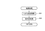
次に、スロットマシン1で行われる抽選処理プログラムについて図16に基づき説明する。図16は抽選処理プログラムのフローチャートである。前記図14のメイン処理プログラムのS12において、抽選処理が行われるが、そのためには、先ず、図16のS31に進んで、シンボル決定処理を行う。ここでは、通常ゲームにおいて、有効入賞ラインL上に停止表示される図柄を、各可変表示部22乃至24毎に決定している。具体的には、上述したように、各可変表示部22乃至24毎に対応するように3つの乱数値を、乱数サンプリング回路56によりサンプリングし、図8の抽選テーブルに基づき、コードNo.を介して、停止表示図柄を決定している。そして、有効入賞ラインL上に停止表示される図柄が決定されると、S32において、役判定処理を行った後に、前記図14のメイン処理プログラムに戻って、S13の通常ゲーム処理に進む。尚、役判定処理では、具体的に言えば、上述したように、前記S31でのコードNo.を介して、図9のテーブルに基づき、当選役及びその配当が決定される。
Next, the lottery processing program executed in the
次に、スロットマシン1で行われる通常ゲーム処理プログラムについて図17に基づき説明する。図17は通常ゲーム処理プログラムのフローチャートである。前記図14のメイン処理プログラムのS13において、通常ゲーム処理が行われるが、そのためには、先ず、図17のS41において、前記図14のS11にて受け付けられたスタートスイッチ57、スピンスイッチ58、1-BETスイッチ59、3-BETスイッチ60又は5-BETスイッチ61から出力されたスイッチ信号に基づいて、可変表示部22乃至24にて各図柄のスクロールが行われる。尚、このとき、可変表示部22乃至24にて表示される各図柄のスクロールが行われているので、可変表示部22乃至24を介して、キャビネット2内の3つのリール220を視認することはできない。
Next, the base game processing program executed in the
そして、S42では、図柄がスクロールしている可変表示部22乃至24に対応するストップボタン27乃至29が遊技者によって押下操作された場合、その押下操作されたストップボタン27乃至29から出力されるスイッチ信号をトリガとして可変表示部22乃至24における各図柄のスクロールが停止される。
In S42, when the player presses the
尚、本実施形態において、各ストップボタン27乃至29は、所謂、遊技者の技術介入を目的として行われる「目押し操作」とは関係がなく、各ストップボタン27乃至29から出力されるスイッチ信号は、あくまでも可変表示部22乃至24にてスクロールされている各図柄を停止表示する際のトリガとなるだけのものである。従って、各可変表示部22乃至24の図柄は、前記図16のS31で判定された結果だけに基づいて停止表示される。言い換えれば、停止操作は、抽選により決定した停止図柄を停止させるまでの演出を実行開始する契機になりうる。
In the present embodiment, each of the
そして、S43においては、S42で各可変表示部22乃至24にて停止表示された当選役の図柄組合せに従って、図9のテーブルに基づき、予め設定されている配当に相当するコイン等が払い出される。尚、かかるS43の処理の後は、前記図14のメイン処理プログラムに戻って、S14の判断処理に進む。
In S43, coins corresponding to a predetermined payout are paid out based on the table of FIG. 9 according to the symbol combination of the winning combination stopped and displayed in each
続いて、スロットマシン1で行われるフリーゲーム処理プログラムについて図18に基づき説明する。図18はフリーゲーム処理プログラムのフローチャートである。前記図14のメイン処理プログラムのS14において、フリーゲームのトリガーが成立していると判断する場合には(S14:YES)、前記図14のS15に進んでフリーゲーム処理が行われるが、そのためには、先ず、図18のS51に進んで、フリーゲーム中の抽選処理が行われる。ここでは、フリーゲームにおいて、各可変表示部22乃至24を介し、有効入賞ラインL上に停止表示される図柄を、各リール220毎に決定している。具体的には、当該S51に移行したタイミングをもって、上述したように、各リール220毎に対応する3つの乱数値を、乱数サンプリング回路56によりサンプリングし、図10の抽選テーブルに基づき、コードNo.を介して、停止表示図柄を決定する。さらに、ここでは、役判定までも行っており、具体的に言えば、上述したように、当該コードNo.を介して、図11のテーブルに基づき、当選役及びその配当を決定する。
Next, a free game processing program executed in the
次に、S52では、下側液晶ディスプレイ4における各可変表示部22乃至24を透過表示して、3つのリール220を視認可能な状態にするとともに、3つのリール220の回転を自動的に開始させ、その後のS53では、遊技者に対して、リール220の回転を停止させる指示をストップボタン27乃至29のいずれかの押下で行うことを、下側液晶ディスプレイ4に表示される文字(例えば、「switch on」)やストップボタン27乃至29の点滅によって促す。
Next, in S52, the
その後、ストップボタン27乃至29のいずれかが遊技者によって押下操作されると、S53において、その押下操作されたストップボタン27乃至29から出力されるスイッチ信号をトリガとして、3つのリール220の回転を自動的に停止させる。尚、本実施形態において、各ストップボタン27乃至29は、所謂、遊技者の技術介入を目的として行われる「目押し操作」とは関係がなく、各ストップボタン27乃至29から出力されるスイッチ信号は、あくまでもスクロールされている各リール220(可変表示部22乃至24)の図柄を停止表示する際のトリガとなるだけのものである。従って、各リール220(可変表示部22乃至24)の図柄は、前記S51で決定された結果だけに基づいて停止表示される。言い換えれば、停止操作は、抽選により決定した停止図柄を停止させるまでの演出を実行開始する契機になりうる。しかしながら、フリーゲームでは、その払出期待値は高く(図13参照)、通常ゲームよりも有利な状態にあるので、ストップボタン27乃至29のいずれかを遊技者が押下操作するたびに配当を得る可能性が大きく、連荘気分を味あうことができる。
Thereafter, when any of the
そして、前記S54の処理が実行された後は、S54において、当選役に応じた枚数のコインの払い出しを行う。次に、S55に進んで、フリーゲームの実行回数が、前記図14のS12で決定された回数に到達したか否かを判断している。このとき、フリーゲームの実行回数が、前記図14のS12で決定された回数に到達していないと判断する場合には(S55:NO)、S51に戻って、上述した処理を繰り返す一方、前記図14のS12で決定された回数に到達したと判断した場合には(S55:YES)、フリーゲーム処理プログラムを終了させる。 Then, after the processing of S54 is executed, in S54, coins corresponding to the winning combination are paid out. Next, in S55, it is determined whether or not the number of executions of the free game has reached the number determined in S12 of FIG. At this time, if it is determined that the number of executions of the free game has not reached the number determined in S12 of FIG. 14 (S55: NO), the process returns to S51 and repeats the above-described process, When it is determined that the number of times determined in S12 of FIG. 14 has been reached (S55: YES), the free game processing program is terminated.
次に、本実施の形態のスロットマシン1で行われるシフト演出処理のタイミングについて、図26に基づいて説明する。図26は、回転処理プログラムのフローチャートであり、シフト演出処理を行うタイミングを明確にするために、図17の通常ゲーム処理におけるS41の回転処理を詳しく記載したものである。すなわち、図14のメイン処理プログラムにおけるS12の抽選処理が行われた後は、図26の回転処理プログラムのS61に進んで、下側液晶ディスプレイ4における各可変表示部22乃至24において、3つの図柄列41〜43の変動表示を自動的に開始させる。その後のS62では、シフト演出をするか否かを判断しており、このとき、シフト演出をすると判断した場合には(S62:YES)、S63に進んで、シフト演出処理を行った後に、図17の通常ゲーム処理に戻って、S42の停止制御処理を行う。一方、シフト演出をしないと判断した場合には(S62:NO)、何もすることなく、図17の通常ゲーム処理に戻って、S42の停止制御処理を行う。
Next, the timing of the shift effect process performed in the
ここで、図26のS62において、シフト演出をするか否かの判断は、図25の抽選処理における予告抽選処理のS131の抽選結果に基づいて行われる。図25は抽選処理プログラムのフローチャートである。抽選処理プログラムのフローチャートについては、図16に基づく説明で既に述べているが、予告抽選処理を行うタイミングを明確にするために、図16のフローチャートに対して、予告抽選処理を追加することで、図25のフローチャートを記載している。すなわち、図25に示すように、抽選処理において、S31のシンボル決定処理とS32の役判定処理を行った後に、S131に進んで、予告抽選処理を行う。S131の予告抽選処理では、乱数サンプリング回路56を介してサンプリングされた乱数値をもって、シフト演出をするか否かを決定し、シフト演出をすると決定した場合には、RAM52内のフラグをたてておく一方、シフト演出をしないと決定した場合には、RAM52内のフラグをそのままにしておく。従って、図26のS62において、シフト演出をするか否かの判断は、RAM52内のフラグがたっているか否かの判断により行われる。尚、図14のメイン処理プログラムにおけるS11のスタート受付処理の際には、常に、RAM52内のフラグを初期化する処理を行っておく。
Here, in S62 of FIG. 26, whether or not to perform the shift effect is determined based on the lottery result of S131 of the notice lottery process in the lottery process of FIG. FIG. 25 is a flowchart of the lottery processing program. The flowchart of the lottery processing program has already been described in the description based on FIG. 16, but in order to clarify the timing for performing the notice lottery process, by adding the notice lottery process to the flowchart of FIG. The flowchart of FIG. 25 is described. That is, as shown in FIG. 25, in the lottery process, after performing the symbol determination process in S31 and the combination determination process in S32, the process proceeds to S131 to perform the notice lottery process. In the notice lottery process in S131, it is determined whether or not to produce a shift effect using the random number values sampled via the random
続いて、シフト演出処理の内容を説明する。上述したように、シフト演出処理が行われるためには、通常ゲームにおける回転処理が実行される必要があり、具体的には、下側液晶ディスプレイ4で行われている通常ゲームにおいて、図21に示すように、各可変表示部22乃至24の図柄がスクロールしながら可変表示される。そして、図22(a)に示すように、下側液晶ディスプレイ4において、民家の周辺の大木に雷が落ちるデモ演出が表示される。このとき、稲妻の点滅に合わせて、効果音の出力とともに、下側液晶ディスプレイ4を透過させたり透過させなかったりすることにより、キャビネット2内の各リール220が視認可能な状態と視認不能な状態を繰り返す。この繰り返しは、一定の周期(例えば、2秒毎)で行ってもよいし、乱数値等を利用してランダムの周期で行ってもよい。このデモ演出の内容は、画像ROM82に記憶されている。その後は、図22(b)に示すように、下側液晶ディスプレイ4の各可変表示部22乃至24を透過させて、キャビネット2内の各リール220が視認可能な状態にする。そして、図22(c)に示すように、下側液晶ディスプレイ4において、民家の周辺の大木から雷が去りゆくデモ演出が表示される。このとき、稲妻の点滅に合わせて、効果音の出力とともに、下側液晶ディスプレイ4を透過させたり透過させなかったりすることにより、キャビネット2内の各リール220が視認可能な状態と視認不能な状態を繰り返す。この繰り返しは、一定の周期(例えば、2秒毎)で行ってもよいし、乱数値等を利用してランダムの周期で行ってもよい。このデモ演出の内容は、画像ROM82に記憶されている。その後は、図22(d)に示すように、下側液晶ディスプレイ4の各可変表示部22乃至24を透過させて、キャビネット2内の各リール220が視認可能な状態にする。
Subsequently, the contents of the shift effect process will be described. As described above, in order to perform the shift effect process, it is necessary to execute the rotation process in the normal game. Specifically, in the normal game performed on the lower
そして、図17の通常ゲーム処理に戻って、S42の停止制御処理を行うと、各可変表示部22乃至24で変動表示されている図柄が自動的に停止され、例えば、図20に示すように、各可変表示部22乃至24の図柄が有効入賞ラインL上に停止表示される。
Then, returning to the normal game process of FIG. 17, when the stop control process of S42 is performed, the symbols variably displayed on the
尚、上述したシフト演出処理は、通常ゲームにおける回転開始処理が実行された後に(S61)、S63のシフト演出処理にまで進んだ場合に行われているが、通常ゲームにおける回転開始処理が実行される前に(S61)、シフト演出処理を行ってもよい。この場合では、例えば、図20に示すように、各可変表示部22乃至24の図柄が有効入賞ラインL上に停止表示された状態において、図22(a)(b)(c)(d)に示すようなシフト演出処理がおこなわれる。その後は、図21に示すように、各可変表示部22乃至24の図柄がスクロールしながら可変表示される。
The above-described shift effect process is performed when the rotation start process in the normal game is executed (S61) and then proceeds to the shift effect process in S63, but the rotation start process in the normal game is executed. (S61), a shift effect process may be performed. In this case, for example, as shown in FIG. 20, in the state where the symbols of the
また、上述したシフト演出処理におけるデモ演出については、複数のデモ演出のパターンを画像ROM82に記憶して準備してもよい。このとき、例えば、図19に示すように、3つのパターンのデモ演出を画像ROM82に記憶して準備しておき、乱数値により抽選を行って、デモ演出のパターンを決定してもよい。すなわち、図19において、抽選テーブルで使用される乱数値の範囲は、0〜63であり、乱数サンプリング回路56を介してサンプリングされた乱数値が0〜2の範囲にある場合には、演出パターン1のデモ演出によるシフト演出処理を行う。また、乱数サンプリング回路56を介してサンプリングされた乱数値が3〜15の範囲にある場合には、演出パターン2のデモ演出によるシフト演出処理を行う。また、乱数サンプリング回路56を介してサンプリングされた乱数値が16〜63の範囲にある場合には、演出パターン3のデモ演出によるシフト演出処理を行う。ここで、乱数サンプリング回路56を介して乱数値をサンプリングするタイミングについては、図15のスタート受付処理に進んだ直後や、図25のS131における予告抽選処理において行うことが望ましい。
Further, the demonstration effect in the shift effect process described above may be prepared by storing a plurality of demonstration effect patterns in the
以上詳細に説明したように、本実施の形態のスロットマシン1は、CPU50が、キャビネット2上の下側液晶ディスプレイ4を制御することにより通常ゲームを実行するとともに(図14のS13)、キャビネット2内のリール220を制御することによりフリーゲームを実行するので(図14のS15)、キャビネット2上の下側液晶ディスプレイ4を用いた通常ゲームとキャビネット2内のリール220を用いたフリーゲームとを実行する遊技機である。さらに、CPU50は、正面側から見てキャビネット2内のリール220の手前側に設けられたキャビネット2上の下側液晶ディスプレイ4を制御することにより、拡散シート35の開口部35A〜35C、導光板36の開口部36A〜36Cを介し、CPU50がキャビネット2上の下側液晶ディスプレイ4の透過率を利用した演出表示であるシフト演出を行うと決定した場合(S62:YES)に、シフト演出処理を行うことにより(図26のS63)、キャビネット2上の下側液晶ディスプレイ4の透過率を調整して実行する演出(キャビネット2内のリール220の存在を認識し得る態様にするために、民家の周辺の大木から雷が落ちたり立ち去るデモ演出を表示し、このとき、稲妻の点滅に合わせて、下側液晶ディスプレイ4を透過させたり透過させなかったりすること)を(図22(a)(c)参照)、キャビネット2上の下側液晶ディスプレイ4を用いた通常ゲームの実行中に行い、また、その一方で、CPU50がキャビネット2上の下側液晶ディスプレイ4の透過率を利用した演出表示であるシフト演出を行うと決定した場合(S62:YES)又はキャビネット2内のリール220を用いたフリーゲームを実行する場合を除いて、キャビネット2内のリール220を隠蔽する。従って、キャビネット2上の下側液晶ディスプレイ4を用いた通常ゲームを実行中に、キャビネット2上の下側液晶ディスプレイ4の透過率を調整して実行する前記演出を行うことにより、キャビネット2内のリール220の存在が認識し得る態様を工夫しているので、キャビネット2内のリール220で行うフリーゲームへの興味を煽ることができるとともに、演出表示の多様化を図ることもできる。
As described in detail above, in the
特に、キャビネット2上の下側液晶ディスプレイ4を用いた通常ゲームを実行中に、キャビネット2上の下側液晶ディスプレイ4の透過率を調整して実行する演出が行われると、例えば、透過率を激しく上下させることにより、通常ゲームとは関係しないキャビネット2内のリール220の存在を認識し得る態様になることから、「これから何が行われるのであろう」という期待感を煽ることができる。
In particular, during the execution of the base game using the lower
さらに、CPU50が、キャビネット2上の下側液晶ディスプレイ4の透過率を利用した演出表示であるシフト演出を行うと決定した場合に(S62:YES)、キャビネット2上の下側液晶ディスプレイ4の透過率を調整して実行する演出を行っており、キャビネット2上の下側液晶ディスプレイ4を用いた通常ゲームを実行中であっても、その演出が行われるとは限らないので、その演出が行われることにより、「これから何が行われるのであろう」という期待感をより強く煽ることができる。
Further, when the
また、キャビネット2上の下側液晶ディスプレイ4を用いた通常ゲームが実行中において、キャビネット2上の下側液晶ディスプレイ4の透過率を調整して実行する演出であるシフト演出(図21参照)を、各可変表示部22乃至24の図柄がスクロールしながら可変表示される際に行っており(図26参照)、キャビネット2上の下側液晶ディスプレイ4を用いた通常ゲームが展開中にその演出表示が行われるので、「これから何が行われるのであろう」という期待感を、キャビネット2上の下側液晶ディスプレイ4を用いた通常ゲームの結果(各可変表示部22乃至24の図柄が有効入賞ラインL上に停止表示されること)にまで絡ませて煽ることができる。
In addition, a shift effect (see FIG. 21), which is an effect that is executed by adjusting the transmittance of the lower
尚、本発明は上記実施の形態に限定されるものでなく、その趣旨を逸脱しない範囲で様々な変更が可能である。
例えば、本実施の形態のスロットマシン1では、上述したシフト演出処理において、民家の周辺の大木に雷が落ちたり去るゆくデモ演出が下側液晶ディスプレイ4で表示され(図26のS63)、このとき、稲妻の点滅に合わせて、下側液晶ディスプレイ4を透過させたり透過させなかったりすることにより、キャビネット2内の各リール220が視認可能な状態と視認不能な状態を繰り返していたが、この点、下側液晶ディスプレイ4を次第に透過させることにより、キャビネット2内の各リール220が徐々に視認可能な状態にしたり、下側液晶ディスプレイ4を次第に透過させないようにして、キャビネット2内の各リール220が徐々に視認不能な状態にしてもよい。
In addition, this invention is not limited to the said embodiment, A various change is possible in the range which does not deviate from the meaning.
For example, in the
また、本実施の形態のスロットマシン1で行われるシフト演出処理のタイミングについては、別の形態として、図26に基づいて説明することもできる。図26は、回転処理プログラムのフローチャートであり、シフト演出処理を行うタイミングを明確にするために、図18のフリーゲーム処理におけるS52の回転処理を詳しく記載したものとする。すなわち、図18のフリーゲーム処理において、S51のフリーゲーム処理が行われた後は、図26の回転処理プログラムのS61に進んで、下側液晶ディスプレイ4における各可変表示部22乃至24を透過表示して、3つのリール220を視認可能な状態にするとともに、3つのリール220の回転を自動的に開始させる。その後のS62では、シフト演出をするか否かを判断しており、このとき、シフト演出をすると判断した場合には(S62:YES)、S63に進んで、シフト演出処理を行った後に、図18のフリーゲーム処理に戻って、S53の停止制御処理を行う。一方、シフト演出をしないと判断した場合には(S62:NO)、何もすることなく、図18のフリーゲーム処理に戻って、S53の停止制御処理を行う。
Moreover, the timing of the shift effect process performed in the
ここで、図26のS62において、シフト演出をするか否かの判断は、図25の抽選処理における予告抽選処理のS131の抽選結果に基づいて行われる。図25は抽選処理プログラムのフローチャートである。抽選処理プログラムのフローチャートについては、図16に基づく説明で既に述べているが、予告抽選処理を行うタイミングを明確にするために、図16のフローチャートに対して、予告抽選処理を追加することで、図25のフローチャートを記載している。すなわち、図25に示すように、抽選処理において、S31のシンボル決定処理とS32の役判定処理を行った後に、S131に進んで、予告抽選処理を行う。S131の予告抽選処理では、乱数サンプリング回路56を介してサンプリングされた乱数値をもって、シフト演出をするか否かを決定し、シフト演出をすると決定した場合には、RAM52内のフラグをたてておく一方、シフト演出をしないと決定した場合には、RAM52内のフラグをそのままにしておく。従って、図26のS62において、シフト演出をするか否かの判断は、RAM52内のフラグがたっているか否かの判断により行われる。尚、図14のメイン処理プログラムにおけるS11のスタート受付処理の際には、常に、RAM52内のフラグを初期化する処理を行っておく。
Here, in S62 of FIG. 26, whether or not to perform the shift effect is determined based on the lottery result of S131 of the notice lottery process in the lottery process of FIG. FIG. 25 is a flowchart of the lottery processing program. The flowchart of the lottery processing program has already been described in the description based on FIG. 16, but in order to clarify the timing for performing the notice lottery process, by adding the notice lottery process to the flowchart of FIG. The flowchart of FIG. 25 is described. That is, as shown in FIG. 25, in the lottery process, after performing the symbol determination process in S31 and the combination determination process in S32, the process proceeds to S131 to perform the notice lottery process. In the notice lottery process in S131, it is determined whether or not to produce a shift effect using the random number values sampled via the random
続いて、シフト演出処理の内容を説明する。上述したように、シフト演出処理が行われるためには、フリーゲームにおける回転処理が実行される必要があるが、そのためには、下側液晶ディスプレイ4で行われている通常ゲームにおいて、図21に示すように、各可変表示部22乃至24の図柄がスクロールしながら可変表示された後で、図20に示すように、可変表示部23にトリガーシンボル97が有効入賞ラインL上に停止表示されて、通常ゲームからフリーゲームに移行されればよい。尚、このとき、可変表示部22及び24の有効入賞ラインL上には、いずれの図柄が停止表示されてもよい。そして、フリーゲームに移行すると、図23(a)に示すように、下側液晶ディスプレイ4の各可変表示部22乃至24を透過させて、キャビネット2内の各リール220が視認可能な状態にした後、フリーゲームにおける回転開始処理が実行され(S61)、図23(b)に示すように、各リール220に形成された図柄列141〜143がスクロールしながら可変表示される。その後、S63のシフト演出処理まで進むと、図23(c)に示すように、下側液晶ディスプレイ4において、民家の周辺の大木に雷が落ちるデモ演出が表示される。このとき、稲妻の点滅に合わせて、効果音の出力とともに、下側液晶ディスプレイ4を透過させたり透過させなかったりすることにより、キャビネット2内の各リール220が視認可能な状態と視認不能な状態を繰り返す。この繰り返しは、一定の周期(例えば、2秒毎)で行ってもよいし、乱数値等を利用してランダムの周期で行ってもよい。このデモ演出の内容は、画像ROM82に記憶されている。さらに、図23(d)に示すように、下側液晶ディスプレイ4において、民家の周辺の大木から雷が去りゆくデモ演出が表示される。このとき、稲妻の点滅に合わせて、効果音の出力とともに、下側液晶ディスプレイ4を透過させたり透過させなかったりすることにより、キャビネット2内の各リール220が視認可能な状態と視認不能な状態を繰り返す。この繰り返しは、一定の周期(例えば、2秒毎)で行ってもよいし、乱数値等を利用してランダムの周期で行ってもよい。このデモ演出の内容は、画像ROM82に記憶されている。
Subsequently, the contents of the shift effect process will be described. As described above, in order to perform the shift effect process, it is necessary to execute the rotation process in the free game. For that purpose, in the normal game performed on the lower
その後、図18のフリーゲーム処理に戻って、S53の停止制御処理を行うと、3つのリール220の回転が自動的に停止され、例えば、図23(a)に示すように、キャビネット2内のリール220により可変表示された3つの図柄列141〜143の一部が有効入賞ラインL上に停止表示される。
Then, returning to the free game process of FIG. 18, when the stop control process of S53 is performed, the rotation of the three
尚、上述したシフト演出処理は、フリーゲームにおける回転開始処理が実行された後に(S61)、S63のシフト演出処理にまで進んだ場合に行われているが、フリーゲームにおける回転開始処理が実行される前に(S61)、シフト演出処理を行ってもよい。この場合では、図24(a)に示すように、下側液晶ディスプレイ4の各可変表示部22乃至24を透過させて、キャビネット2内の各リール220が視認可能な状態にした後、図24(b)に示すように、下側液晶ディスプレイ4において、民家の周辺の大木に雷が落ちるデモ演出が表示される。このとき、稲妻の点滅に合わせて、効果音の出力とともに、下側液晶ディスプレイ4を透過させたり透過させなかったりすることにより、キャビネット2内の各リール220が視認可能な状態と視認不能な状態を繰り返す。この繰り返しは、一定の周期(例えば、2秒毎)で行ってもよいし、乱数値等を利用してランダムの周期で行ってもよい。このデモ演出の内容は、画像ROM82に記憶されている。さらに、図24(c)に示すように、下側液晶ディスプレイ4において、民家の周辺の大木から雷が去りゆくデモ演出が表示される。このとき、稲妻の点滅に合わせて、効果音の出力とともに、下側液晶ディスプレイ4を透過させたり透過させなかったりすることにより、キャビネット2内の各リール220が視認可能な状態と視認不能な状態を繰り返す。この繰り返しは、一定の周期(例えば、2秒毎)で行ってもよいし、乱数値等を利用してランダムの周期で行ってもよい。このデモ演出の内容は、画像ROM82に記憶されている。その後は、図24(d)に示すように、各リール220に形成された図柄列141〜143がスクロールしながら可変表示される。
The above-described shift effect process is performed when the rotation start process in the free game is executed (S61) and then proceeds to the shift effect process in S63, but the rotation start process in the free game is executed. (S61), a shift effect process may be performed. In this case, as shown in FIG. 24A, the
また、本実施の形態のスロットマシン1においては、通常ゲームでは、乱数サンプリング回路56を介してサンプリングされた乱数値によって、有効入賞ラインL上に停止表示される図柄を各可変表示部22乃至24毎に決定していたが(図8参照)、この点、乱数サンプリング回路56を介してサンプリングされた乱数値によって、各可変表示部22乃至24における有効入賞ラインL上に停止表示される全ての図柄を決定してもよい。そのためには、図27に示す当選役の抽選テーブルを使用する。図27は、3つの可変表示部を使用して通常ゲームを行う場合における当選役の抽選テーブル及びその配当を示す説明図である。
Further, in the
図27において、当選役の抽選テーブルで使用される乱数値の範囲は、0〜1270であり、乱数サンプリング回路56を介してサンプリングされた乱数値が0〜9の範囲にある場合には、ジョーカーに当選し、フリーゲームのトリガーの配当を得る。この場合、可変表示部23においてトリガーシンボル97が有効入賞ラインL上に停止表示され、フリーゲームに移行することができる。
In FIG. 27, the range of random values used in the winning combination lottery table is 0 to 1270, and when the random value sampled through the random
また、乱数サンプリング回路56を介してサンプリングされた乱数値が、10〜32の範囲にある場合には、「7−7−7」に当選し、「100」の配当を得る。この場合、各可変表示部22乃至24において、セブン94が有効入賞ラインL上に停止表示される。同様に、サンプリングされた乱数値が33〜35の範囲にある場合には、「3BAR−3BAR−3BAR」に当選し、「5」の配当を得る。この場合、各可変表示部22乃至24において、トリプルBAR91が有効入賞ラインL上に停止表示される。同様に、サンプリングされた乱数値が36〜58の範囲にある場合には、「2BAR−2BAR−2BAR」に当選し、「3」の配当を得る。この場合、各可変表示部22乃至24において、ダブルBAR93が有効入賞ラインL上に停止表示される。同様に、サンプリングされた乱数値が59〜203の範囲にある場合には、「BAR−BAR−BAR」に当選し、「2」の配当を得る。この場合、各可変表示部22乃至24において、シングルBAR95が有効入賞ラインL上に停止表示される。同様に、サンプリングされた乱数値が204〜257の範囲にある場合には、「チェリー−チェリー−チェリー」に当選し、「1」の配当を得る。この場合、各可変表示部21乃至25において、チェリー92が有効入賞ラインL上に停止表示される。
If the random value sampled through the random
尚、サンプリングされた乱数値が258〜1270の範囲にある場合には、「はずれ」に当選する。この場合、各可変表示部22乃至24においては、上述した図柄の組合せ以外が有効入賞ラインL上に停止表示されるが、配当はない。
When the sampled random number value is in the range of 258 to 1270, “out” is won. In this case, in each of the
また、本実施の形態のスロットマシン1においては、フリーゲームでも、乱数サンプリング回路56を介してサンプリングされた乱数値によって、各可変表示部22乃至24を介して有効入賞ラインL上に停止表示される図柄を各リール220毎に決定していたが(図10参照)、この点、乱数サンプリング回路56を介してサンプリングされた乱数値によって、各可変表示部22乃至24を介して有効入賞ラインL上に停止表示される全ての図柄を決定してもよい。そのためには、図28に示す当選役の抽選テーブルを使用する。図28は、3つの可変表示部を介してフリーゲームを行う場合における当選役の抽選テーブル及びその配当を示す説明図である。
In the
図28において、当選役の抽選テーブルで使用される乱数値の範囲は、0〜127であり、乱数サンプリング回路56を介してサンプリングされた乱数値が、0〜11の範囲にある場合には、「7−7−Tr」に当選し、「300」の配当を得る。この場合、各可変表示部22乃至24を介して、セブンシンボル191、セブンシンボル191、トリプルシンボル192が有効入賞ラインL上に停止表示される。同様に、サンプリングされた乱数値が12〜49の範囲にある場合には、「7−7−Do」に当選し、「200」の配当を得る。この場合、各可変表示部22乃至24を介して、セブンシンボル191、セブンシンボル191、ダブルシンボル193が有効入賞ラインL上に停止表示される。同様に、サンプリングされた乱数値が50〜87の範囲にある場合には、「7−7−7」に当選し、「100」の配当を得る。この場合、各可変表示部22乃至24を介して、セブンシンボル191、セブンシンボル191、セブンシンボル191が有効入賞ラインL上に停止表示される。
In FIG. 28, the range of random values used in the lottery table for winning combinations is 0 to 127, and when the random values sampled through the random
尚、サンプリングされた乱数値が88〜127の範囲にある場合には、「はずれ」に当選する。この場合、各可変表示部22乃至24を介して、上述した図柄の組合せ以外が有効入賞ラインL上に停止表示されるが、配当はない。
If the sampled random number value is in the range of 88 to 127, “out” is won. In this case, the combinations other than the above-described symbol combinations are stopped and displayed on the effective pay line L through the
また、本実施の形態のスロットマシン1では、「第2ゲーム」として、フリーゲームを行っているが、これに限らず、例えば、通常ゲームに引き続いて行われる所謂セカンドゲームを行ってもよい。
また、本実施の形態のスロットマシン1では、通常ゲームとフリーゲームにおいて、図柄を用いたゲームを行っているが(図6、図7参照)、これに限らず、例えば、カードを用いたポーカーなどのゲームを行ってもよい。
In the
Further, in the
また、本実施の形態のスロットマシン1では、下側液晶ディスプレイ4において、図3に示すように、各開口部35A〜38Aが、相互に一致するように重ねられて可変表示部22(図1参照)を構成し、各開口部35B〜38Bも同様にして可変表示部23(図1参照)を構成し、各開口部35C〜38も同様にして可変表示部24(図1参照)を構成することによって、各可変表示部22〜24の視認性を確保する透過領域を構成している。この点、各可変表示部22〜24たる3つの透過領域の形状は、それぞれ、各リール220の幅に合わせた縦長の長方形をしているが、これに限らず、例えば、下側液晶ディスプレイ4の全面を透過領域にしてもよい。
Further, in the
また、本実施の形態のスロットマシン1では、下側液晶ディスプレイ4において、通常ゲームの場合は、不透過表示された可変表示部22乃至24にて、図6の図柄列41〜43のスクロール表示・停止表示が行われ、また、フリーゲームの場合は、透過表示された可変表示表示部22乃至24を介し、図7の図柄列141〜143のスクロール表示・停止表示が行われる。この点、通常ゲームの場合は、可変表示部22乃至24以外の領域において、図6の図柄列41〜43のスクロール表示・停止表示が行われてもよい。
Further, in the
また、本実施の形態のスロットマシン1では、「透過表示手段」として、下側液晶ディスプレイ4の透過率を調整することで、キャビネット2内のリール220を透過表示したりしなかったりしているが、この点、下側液晶ディスプレイ4とリール220との間に付設したシャッター構造等を、「透過表示手段」として用いることにより、キャビネット2内のリール220を透過表示したりしなかったりしてもよい。
Further, in the
また、本実施の形態のスロットマシン1では、「透過表示手段」を有する「演出表示装置」として、キャビネット2内のリール220を透過表示したりしなかったりする下側液晶ディスプレイ4を用いているが、これに限らず、例えば、透明EL等を用いてもよい。
Further, in the
本発明は、演出表示装置と可変表示装置とを備えた遊技機に関するものであり、前記演出表示装置が前記可変表示装置の状態を透過して表示するものであるとともにゲームを実行できるものである場合に適用がある。 The present invention relates to a gaming machine including an effect display device and a variable display device, in which the effect display device displays a state of the variable display device in a transparent manner and can execute a game. There are cases where it applies.
1 スロットマシン
2 キャビネット
4 下側液晶ディスプレイ
22〜24 可変表示部
27〜29 ストップボタン
41〜43 図柄列
50 CPU
141〜143 図柄列
220 リール
L 有効入賞ライン
DESCRIPTION OF
141-143
Claims (2)
正面側から見て、前記演出表示装置の背後に配設された可変表示装置と、
前記演出表示装置を用いた第1ゲーム又は前記可変表示装置を用いた第2ゲームを実行するゲーム制御手段と、を備え、
前記演出表示装置は、透過率を調整することにより、前記可変表示装置の状態を透過して表示する透過表示手段を有し、
前記透過表示手段は、前記ゲーム制御手段が前記透過表示手段を用いた演出を行うと決定した場合に、前記透過表示手段の透過率を調整して実行する演出を前記第1ゲームの実行中に行う一方で、前記ゲーム制御手段が前記透過表示手段を用いた演出を行うと決定した場合又は前記第2ゲームを実行する場合を除いて、前記可変表示装置を隠蔽すること、を特徴とする遊技機。 An effect display device for displaying the effect;
A variable display device disposed behind the effect display device as seen from the front side;
Game control means for executing a first game using the effect display device or a second game using the variable display device,
The effect display device has a transmissive display means for transmissively displaying the state of the variable display device by adjusting the transmittance,
The transparent display means performs an effect that is executed by adjusting the transmittance of the transparent display means when the game control means determines to perform an effect using the transparent display means during execution of the first game. On the other hand, a game characterized in that the variable display device is concealed except when the game control means decides to perform an effect using the transparent display means or when the second game is executed. Machine.
前記透過表示手段は、前記ゲーム制御手段が前記第1ゲームでの前記演出表示装置の表示内容を変更する際に、前記透過表示手段の透過率を調整して実行する演出を行うこと、を特徴とする遊技機。 A gaming machine according to claim 1,
The transparent display means performs an effect that is executed by adjusting the transmittance of the transparent display means when the game control means changes the display content of the effect display device in the first game. A gaming machine.
Priority Applications (6)
| Application Number | Priority Date | Filing Date | Title |
|---|---|---|---|
| JP2003306489A JP2005073852A (en) | 2003-08-29 | 2003-08-29 | Game machine |
| AU2004205206A AU2004205206B2 (en) | 2003-08-29 | 2004-08-24 | Gaming machine |
| US10/926,039 US7510476B2 (en) | 2003-08-29 | 2004-08-26 | Gaming machine with a display controller for alternatively executing an effect and displaying a first game or alternatively executing the effect and a second game |
| ZA200406852A ZA200406852B (en) | 2003-08-29 | 2004-08-27 | Gaming machine. |
| CNB2004100685715A CN100340315C (en) | 2003-08-29 | 2004-08-27 | Gaming machine |
| EP04020550A EP1526487A1 (en) | 2003-08-29 | 2004-08-30 | Gaming machine |
Applications Claiming Priority (1)
| Application Number | Priority Date | Filing Date | Title |
|---|---|---|---|
| JP2003306489A JP2005073852A (en) | 2003-08-29 | 2003-08-29 | Game machine |
Publications (1)
| Publication Number | Publication Date |
|---|---|
| JP2005073852A true JP2005073852A (en) | 2005-03-24 |
Family
ID=34214094
Family Applications (1)
| Application Number | Title | Priority Date | Filing Date |
|---|---|---|---|
| JP2003306489A Withdrawn JP2005073852A (en) | 2003-08-29 | 2003-08-29 | Game machine |
Country Status (6)
| Country | Link |
|---|---|
| US (1) | US7510476B2 (en) |
| EP (1) | EP1526487A1 (en) |
| JP (1) | JP2005073852A (en) |
| CN (1) | CN100340315C (en) |
| AU (1) | AU2004205206B2 (en) |
| ZA (1) | ZA200406852B (en) |
Cited By (4)
| Publication number | Priority date | Publication date | Assignee | Title |
|---|---|---|---|---|
| JP2007068903A (en) * | 2005-09-09 | 2007-03-22 | Aruze Corp | Game machine |
| JP2007068905A (en) * | 2005-09-09 | 2007-03-22 | Aruze Corp | Game machine |
| JP2010508950A (en) * | 2006-11-07 | 2010-03-25 | トヴィス カンパニー リミテッド | Slot machine-reel game conversion image on screen display panel reflective structure |
| JP2017032635A (en) * | 2015-07-29 | 2017-02-09 | 株式会社大一商会 | Image display system |
Families Citing this family (85)
| Publication number | Priority date | Publication date | Assignee | Title |
|---|---|---|---|---|
| US20070072665A1 (en) * | 2001-09-28 | 2007-03-29 | Igt, A Nevada Corporation | Methods, Apparatuses And Systems for Multilayer Gaming |
| US20090124383A1 (en) * | 2007-11-09 | 2009-05-14 | Igt | Apparatus for use with interactive table games and methods of use |
| US8715058B2 (en) * | 2002-08-06 | 2014-05-06 | Igt | Reel and video combination machine |
| US7841944B2 (en) | 2002-08-06 | 2010-11-30 | Igt | Gaming device having a three dimensional display device |
| US20070004513A1 (en) * | 2002-08-06 | 2007-01-04 | Igt | Gaming machine with layered displays |
| US20050153775A1 (en) * | 2004-01-12 | 2005-07-14 | Griswold Chauncey W. | Multiple-state display for a gaming apparatus |
| JP2004166820A (en) * | 2002-11-18 | 2004-06-17 | Aruze Corp | Game machine |
| JP2004166963A (en) * | 2002-11-20 | 2004-06-17 | Aruze Corp | Gaming machine |
| ZA200308997B (en) * | 2002-11-20 | 2005-08-31 | Universal Entertainment Corp | Gaming machine and display device therefor |
| US8096867B2 (en) | 2002-11-20 | 2012-01-17 | Universal Entertainment Corporation | Gaming machine and display device with fail-tolerant image displaying |
| JP2004166962A (en) * | 2002-11-20 | 2004-06-17 | Aruze Corp | Game machine |
| US7892094B2 (en) * | 2003-05-14 | 2011-02-22 | Universal Entertainment Corporation | Gaming machine with a light guiding plate subjected to a light scattering process and having a light deflection pattern |
| US20040248642A1 (en) * | 2003-05-28 | 2004-12-09 | Rothschild Wayne H. | Adaptable gaming machine in a gaming network |
| JP2005073852A (en) * | 2003-08-29 | 2005-03-24 | Aruze Corp | Game machine |
| US7857700B2 (en) * | 2003-09-12 | 2010-12-28 | Igt | Three-dimensional autostereoscopic image display for a gaming apparatus |
| US9564004B2 (en) | 2003-10-20 | 2017-02-07 | Igt | Closed-loop system for providing additional event participation to electronic video game customers |
| US20070155469A1 (en) * | 2003-10-20 | 2007-07-05 | Sam Johnson | Automatic funding of paragames on electronic gaming platform |
| US7309284B2 (en) * | 2004-01-12 | 2007-12-18 | Igt | Method for using a light valve to reduce the visibility of an object within a gaming apparatus |
| US8408998B2 (en) * | 2004-09-28 | 2013-04-02 | Wms Gaming Inc. | Transmissive LCD display system for gaming machine |
| US8616969B2 (en) * | 2004-11-02 | 2013-12-31 | Wms Gaming Inc. | Gaming machine with LED display that is an integral part of game play |
| US9613491B2 (en) | 2004-12-16 | 2017-04-04 | Igt | Video gaming device having a system and method for completing wagers and purchases during the cash out process |
| US20060166726A1 (en) | 2005-01-24 | 2006-07-27 | Jay Chun | Methods and systems for playing baccarat jackpot |
| US8210920B2 (en) | 2005-01-24 | 2012-07-03 | Jay Chun | Methods and systems for playing baccarat jackpot |
| US7922587B2 (en) | 2005-01-24 | 2011-04-12 | Jay Chun | Betting terminal and system |
| US9940778B2 (en) | 2005-01-24 | 2018-04-10 | Igt | System for monitoring and playing a plurality of live casino table games |
| US8308559B2 (en) | 2007-05-07 | 2012-11-13 | Jay Chun | Paradise box gaming system |
| US8920238B2 (en) | 2005-01-24 | 2014-12-30 | Jay Chun | Gaming center allowing switching between games based upon historical results |
| US7914368B2 (en) | 2005-08-05 | 2011-03-29 | Jay Chun | Methods and systems for playing baccarat jackpot with an option for insurance betting |
| US20060281532A1 (en) * | 2005-06-10 | 2006-12-14 | Aruze Corp. | Gaming machine |
| WO2007011717A2 (en) * | 2005-07-15 | 2007-01-25 | Wms Gaming Inc. | Wagering game machine with transmissive lcd object blocking |
| US7878910B2 (en) * | 2005-09-13 | 2011-02-01 | Igt | Gaming machine with scanning 3-D display system |
| US8231464B2 (en) * | 2005-12-19 | 2012-07-31 | Wms Gaming Inc. | Multigame gaming machine with transmissive display |
| US9028329B2 (en) | 2006-04-13 | 2015-05-12 | Igt | Integrating remotely-hosted and locally rendered content on a gaming device |
| US20070243928A1 (en) * | 2006-04-13 | 2007-10-18 | Igt | Casino gaming incentives using game themes, game types, paytables, denominations |
| US8992304B2 (en) | 2006-04-13 | 2015-03-31 | Igt | Methods and systems for tracking an event of an externally controlled interface |
| US8968077B2 (en) | 2006-04-13 | 2015-03-03 | Idt | Methods and systems for interfacing with a third-party application |
| US8777737B2 (en) | 2006-04-13 | 2014-07-15 | Igt | Method and apparatus for integrating remotely-hosted and locally rendered content on a gaming device |
| US8512139B2 (en) * | 2006-04-13 | 2013-08-20 | Igt | Multi-layer display 3D server based portals |
| US8784196B2 (en) | 2006-04-13 | 2014-07-22 | Igt | Remote content management and resource sharing on a gaming machine and method of implementing same |
| US10026255B2 (en) | 2006-04-13 | 2018-07-17 | Igt | Presentation of remotely-hosted and locally rendered content for gaming systems |
| JP2007323276A (en) * | 2006-05-31 | 2007-12-13 | Toshiba Corp | Communication apparatus and communication method |
| JP2008017945A (en) | 2006-07-11 | 2008-01-31 | Aruze Corp | Game machine and game control method |
| JP4215790B2 (en) * | 2006-08-29 | 2009-01-28 | Necディスプレイソリューションズ株式会社 | Silencer, electronic device, and method for controlling silencing characteristics |
| US20090156303A1 (en) * | 2006-11-10 | 2009-06-18 | Igt | Bonusing Architectures in a Gaming Environment |
| US9311774B2 (en) | 2006-11-10 | 2016-04-12 | Igt | Gaming machine with externally controlled content display |
| US8727855B2 (en) * | 2006-11-13 | 2014-05-20 | Igt | Three-dimensional paylines for gaming machines |
| US8360847B2 (en) | 2006-11-13 | 2013-01-29 | Igt | Multimedia emulation of physical reel hardware in processor-based gaming machines |
| US20080113747A1 (en) * | 2006-11-13 | 2008-05-15 | Igt | Mechanical reel hardware simulation using multiple layer displays |
| AU2007323962B2 (en) | 2006-11-13 | 2012-07-12 | Igt | Single plane spanning mode across independently driven displays |
| US8192281B2 (en) * | 2006-11-13 | 2012-06-05 | Igt | Simulated reel imperfections |
| US8357033B2 (en) * | 2006-11-13 | 2013-01-22 | Igt | Realistic video reels |
| US8210922B2 (en) * | 2006-11-13 | 2012-07-03 | Igt | Separable game graphics on a gaming machine |
| US8142273B2 (en) * | 2006-11-13 | 2012-03-27 | Igt | Presentation of wheels on gaming machines having multi-layer displays |
| US9292996B2 (en) * | 2006-12-19 | 2016-03-22 | Igt | Distributed side wagering methods and systems |
| JP2008178519A (en) * | 2007-01-24 | 2008-08-07 | Aruze Corp | Game machine |
| US8616953B2 (en) * | 2007-08-31 | 2013-12-31 | Igt | Reel symbol resizing for reel based gaming machines |
| US8115700B2 (en) * | 2007-09-20 | 2012-02-14 | Igt | Auto-blanking screen for devices having multi-layer displays |
| US8012010B2 (en) | 2007-09-21 | 2011-09-06 | Igt | Reel blur for gaming machines having simulated rotating reels |
| US8758144B2 (en) * | 2007-10-23 | 2014-06-24 | Igt | Separable backlighting system |
| US8210944B2 (en) | 2007-10-29 | 2012-07-03 | Igt | Gaming system having display device with changeable wheel |
| US8172666B2 (en) * | 2008-04-01 | 2012-05-08 | Aruze Gaming America, Inc. | Slot machine |
| AU2009202103B2 (en) | 2008-06-25 | 2012-04-12 | Aristocrat Technologies Australia Pty Limited | A gaming system and a method of gaming |
| US20100081492A1 (en) * | 2008-09-30 | 2010-04-01 | Marks Daniel M | Method of playing a poker game using cards with randomly generated bonus inititator indicia |
| US8187083B2 (en) * | 2008-11-13 | 2012-05-29 | Aruze Gaming America, Inc. | Gaming machine executing free game and control method thereof |
| US8393951B2 (en) * | 2008-11-14 | 2013-03-12 | Aruze Gaming America, Inc. | Gaming system having a plurality of gaming machines linked by network and control method thereof |
| US8851977B2 (en) * | 2009-09-29 | 2014-10-07 | Wms Gaming Inc. | Dual liquid crystal shutter display |
| US8425316B2 (en) | 2010-08-03 | 2013-04-23 | Igt | Methods and systems for improving play of a bonus game on a gaming machine and improving security within a gaming establishment |
| US8203659B2 (en) * | 2010-08-13 | 2012-06-19 | Litemax Electronics Inc. | LCD display and gaming machine combination |
| US8298081B1 (en) | 2011-06-16 | 2012-10-30 | Igt | Gaming system, gaming device and method for providing multiple display event indicators |
| US9652928B2 (en) * | 2011-08-12 | 2017-05-16 | Bally Gaming, Inc. | Gaming machine, gaming machine display and method |
| US9524609B2 (en) | 2011-09-30 | 2016-12-20 | Igt | Gaming system, gaming device and method for utilizing mobile devices at a gaming establishment |
| US9466173B2 (en) | 2011-09-30 | 2016-10-11 | Igt | System and method for remote rendering of content on an electronic gaming machine |
| US8605114B2 (en) | 2012-02-17 | 2013-12-10 | Igt | Gaming system having reduced appearance of parallax artifacts on display devices including multiple display screens |
| US9129469B2 (en) | 2012-09-11 | 2015-09-08 | Igt | Player driven game download to a gaming machine |
| US8663009B1 (en) | 2012-09-17 | 2014-03-04 | Wms Gaming Inc. | Rotatable gaming display interfaces and gaming terminals with a rotatable display interface |
| WO2014053096A1 (en) | 2012-10-02 | 2014-04-10 | Novel Tech International Limited | System and method for providing remote wagering games in live table game system |
| US8821239B1 (en) | 2013-07-22 | 2014-09-02 | Novel Tech International Limited | Gaming table system allowing player choices and multiple outcomes thereby for a single game |
| US8684830B1 (en) | 2013-09-03 | 2014-04-01 | Novel Tech International Limited | Individually paced table game tournaments |
| US9595159B2 (en) | 2013-10-01 | 2017-03-14 | Igt | System and method for multi-game, multi-play of live dealer games |
| US9916735B2 (en) | 2015-07-22 | 2018-03-13 | Igt | Remote gaming cash voucher printing system |
| US10055930B2 (en) | 2015-08-11 | 2018-08-21 | Igt | Gaming system and method for placing and redeeming sports bets |
| US10902696B2 (en) | 2018-09-18 | 2021-01-26 | Aristocrat Technologies Australia Pty Limited | Wheel display with moveable segments |
| US10713880B2 (en) | 2018-09-18 | 2020-07-14 | Aristocrat Technologies Australia Pty Limited | Electronic gaming machine with dynamic display |
| US11710368B2 (en) | 2021-02-26 | 2023-07-25 | Aristocrat Technologies, Inc. | Electronic gaming machine with dynamic display |
| US12387554B2 (en) | 2022-08-30 | 2025-08-12 | Lnw Gaming, Inc. | User input deck for a gaming machine |
Family Cites Families (42)
| Publication number | Priority date | Publication date | Assignee | Title |
|---|---|---|---|---|
| JPH0519100Y2 (en) * | 1985-11-15 | 1993-05-20 | ||
| JP2808581B2 (en) * | 1988-07-07 | 1998-10-08 | 株式会社ソフィア | Gaming equipment |
| US5580055A (en) * | 1993-03-18 | 1996-12-03 | Sigma, Inc. | Amusement device and selectively enhanced display for the same |
| WO1995017932A1 (en) * | 1993-12-28 | 1995-07-06 | Kabushiki Kaisha Ace Denken | Game machine |
| US5530571A (en) | 1995-01-06 | 1996-06-25 | Chen; Hung-Wen | Two-purpose LCD device with scrollable reflecting screen and scrollable diffusing screen |
| US6003867A (en) * | 1997-06-13 | 1999-12-21 | Unislot, Inc. | Reel type slot machine utilizing time-based random game result selection means |
| JPH11244453A (en) * | 1998-03-04 | 1999-09-14 | Aruze Corp | Game machine |
| JPH11305011A (en) * | 1998-04-22 | 1999-11-05 | Dainippon Printing Co Ltd | Lens film and surface light source device |
| JP3906956B2 (en) * | 1998-12-24 | 2007-04-18 | 株式会社 日立ディスプレイズ | Liquid crystal display |
| KR20000060073A (en) * | 1999-03-11 | 2000-10-16 | 구본준 | Backlight of a liquid crystal display device |
| US7204753B2 (en) * | 2000-02-28 | 2007-04-17 | Denso Corporation | Pattern display device and game machine including the same |
| JP2001347042A (en) | 2000-06-07 | 2001-12-18 | Aruze Corp | Gaming machine |
| US7019810B2 (en) | 2001-04-20 | 2006-03-28 | Hewlett-Packard Development Company, L.P. | Fiber faceplate suspended particle display |
| WO2002091319A2 (en) * | 2001-05-04 | 2002-11-14 | Igt | Light emitting interface displays for a gaming machine |
| US6517433B2 (en) * | 2001-05-22 | 2003-02-11 | Wms Gaming Inc. | Reel spinning slot machine with superimposed video image |
| KR20030008790A (en) * | 2001-07-20 | 2003-01-29 | 삼성전자 주식회사 | Liquid crystal display device |
| US20030027624A1 (en) * | 2001-08-03 | 2003-02-06 | Gilmore Jason C. | Hybrid slot machine |
| US6517437B1 (en) * | 2001-08-31 | 2003-02-11 | Igt | Casino gaming apparatus with multiple display |
| AUPR874201A0 (en) * | 2001-11-08 | 2001-11-29 | Aristocrat Technologies Australia Pty Limited | Gaming machine display |
| JP2004024529A (en) * | 2002-06-25 | 2004-01-29 | Aruze Corp | Gaming machine |
| JP2004024528A (en) * | 2002-06-25 | 2004-01-29 | Aruze Corp | Gaming machine |
| JP2004081475A (en) * | 2002-06-25 | 2004-03-18 | Aruze Corp | Gaming machine |
| US7841944B2 (en) * | 2002-08-06 | 2010-11-30 | Igt | Gaming device having a three dimensional display device |
| US20050153775A1 (en) * | 2004-01-12 | 2005-07-14 | Griswold Chauncey W. | Multiple-state display for a gaming apparatus |
| JP2004073651A (en) * | 2002-08-21 | 2004-03-11 | Aruze Corp | Gaming machine |
| US7404766B2 (en) * | 2002-11-19 | 2008-07-29 | Aruze Corp. | Gaming machine |
| US7207883B2 (en) * | 2002-11-19 | 2007-04-24 | Aruze Corporation | Gaming machine |
| JP2004166879A (en) * | 2002-11-19 | 2004-06-17 | Aruze Corp | Gaming machine |
| US7329181B2 (en) * | 2002-11-20 | 2008-02-12 | Aruze Corporation | Gaming machine with multilayered liquid crystal display for displaying images based on a priority order |
| JP2004166961A (en) * | 2002-11-20 | 2004-06-17 | Aruze Corp | Gaming machine |
| JP2004166962A (en) * | 2002-11-20 | 2004-06-17 | Aruze Corp | Game machine |
| JP2004166959A (en) * | 2002-11-20 | 2004-06-17 | Aruze Corp | Gaming machine |
| JP2004166964A (en) * | 2002-11-20 | 2004-06-17 | Aruze Corp | Gaming machine |
| AU2004200269A1 (en) * | 2003-01-27 | 2004-08-12 | Aruze Corp | Gaming machine |
| US7374488B2 (en) * | 2003-04-17 | 2008-05-20 | Atronic Systems G.M.B.H. | Player insert for a gaming machine, a gaming system and a method of operating a gaming system |
| US7219893B2 (en) * | 2003-05-14 | 2007-05-22 | Aruze Corporation | Gaming machine |
| US6937298B2 (en) * | 2003-05-14 | 2005-08-30 | Aruze Corp. | Gaming machine having a protective member covering drive unit and at least a portion of the light emission means |
| TWI275845B (en) * | 2003-05-23 | 2007-03-11 | Hon Hai Prec Ind Co Ltd | Light guide plate and backlight system using the same |
| JP2005073852A (en) * | 2003-08-29 | 2005-03-24 | Aruze Corp | Game machine |
| JP2005073821A (en) * | 2003-08-29 | 2005-03-24 | Aruze Corp | Game machine |
| EP1531435A3 (en) * | 2003-11-11 | 2005-07-13 | Aruze Corporation | Liquid crystal display device and gaming machine |
| US7309284B2 (en) * | 2004-01-12 | 2007-12-18 | Igt | Method for using a light valve to reduce the visibility of an object within a gaming apparatus |
-
2003
- 2003-08-29 JP JP2003306489A patent/JP2005073852A/en not_active Withdrawn
-
2004
- 2004-08-24 AU AU2004205206A patent/AU2004205206B2/en not_active Ceased
- 2004-08-26 US US10/926,039 patent/US7510476B2/en not_active Expired - Lifetime
- 2004-08-27 ZA ZA200406852A patent/ZA200406852B/en unknown
- 2004-08-27 CN CNB2004100685715A patent/CN100340315C/en not_active Expired - Fee Related
- 2004-08-30 EP EP04020550A patent/EP1526487A1/en not_active Ceased
Cited By (4)
| Publication number | Priority date | Publication date | Assignee | Title |
|---|---|---|---|---|
| JP2007068903A (en) * | 2005-09-09 | 2007-03-22 | Aruze Corp | Game machine |
| JP2007068905A (en) * | 2005-09-09 | 2007-03-22 | Aruze Corp | Game machine |
| JP2010508950A (en) * | 2006-11-07 | 2010-03-25 | トヴィス カンパニー リミテッド | Slot machine-reel game conversion image on screen display panel reflective structure |
| JP2017032635A (en) * | 2015-07-29 | 2017-02-09 | 株式会社大一商会 | Image display system |
Also Published As
| Publication number | Publication date |
|---|---|
| US20050049046A1 (en) | 2005-03-03 |
| CN1589940A (en) | 2005-03-09 |
| US7510476B2 (en) | 2009-03-31 |
| AU2004205206B2 (en) | 2011-01-20 |
| CN100340315C (en) | 2007-10-03 |
| ZA200406852B (en) | 2005-03-01 |
| EP1526487A1 (en) | 2005-04-27 |
| AU2004205206A1 (en) | 2005-03-17 |
Similar Documents
| Publication | Publication Date | Title |
|---|---|---|
| JP2005073852A (en) | Game machine | |
| JP2005073821A (en) | Game machine | |
| EP1600903A2 (en) | Gaming machine | |
| JP2005052636A (en) | Game machine | |
| JP2007054494A (en) | Game machine | |
| US20070060296A1 (en) | Gaming machine | |
| JP2007209528A (en) | Game machine | |
| JP2016106931A (en) | Slot machine | |
| JP2005304745A (en) | Game machine | |
| US20070207851A1 (en) | Gaming machine and gaming method thereof | |
| JP2006325682A (en) | Game machine | |
| US20070060266A1 (en) | Gaming machine | |
| JP2007068850A (en) | Game machine | |
| US20060025204A1 (en) | Gaming machine | |
| JP2005152167A (en) | Game machine | |
| US20060287061A1 (en) | Gaming machine | |
| JP2006326039A (en) | Game machine | |
| JP2005124928A (en) | Game machine | |
| JP2005073825A (en) | Game machine | |
| JP2005087383A (en) | Game machine | |
| JP2005065747A (en) | Game machine | |
| JP2005087384A (en) | Game machine | |
| ZA200504344B (en) | Gaming machine | |
| JP2006181224A (en) | Game machine | |
| JP2006326041A (en) | Game machine |
Legal Events
| Date | Code | Title | Description |
|---|---|---|---|
| A621 | Written request for application examination |
Free format text: JAPANESE INTERMEDIATE CODE: A621 Effective date: 20060621 |
|
| A761 | Written withdrawal of application |
Free format text: JAPANESE INTERMEDIATE CODE: A761 Effective date: 20080123 |