JP2005030983A - measuring device - Google Patents
measuring device Download PDFInfo
- Publication number
- JP2005030983A JP2005030983A JP2003272281A JP2003272281A JP2005030983A JP 2005030983 A JP2005030983 A JP 2005030983A JP 2003272281 A JP2003272281 A JP 2003272281A JP 2003272281 A JP2003272281 A JP 2003272281A JP 2005030983 A JP2005030983 A JP 2005030983A
- Authority
- JP
- Japan
- Prior art keywords
- memory card
- measurement
- measuring apparatus
- firmware
- test piece
- Prior art date
- Legal status (The legal status is an assumption and is not a legal conclusion. Google has not performed a legal analysis and makes no representation as to the accuracy of the status listed.)
- Pending
Links
Images


Landscapes
- Automatic Analysis And Handling Materials Therefor (AREA)
- Investigating Or Analysing Biological Materials (AREA)
Abstract
【課題】 血液などの検体を、試験片に点着し、その呈色反応などから、検体の特性を測定する測定装置において、試験片を造ロットごとに較正するためのデータの供給や、測定装置に組み込まれたファームウェアの更新を安価に提供する。
【解決手段】 測定装置1に較正データ用のメモリカード9もしくはファームウェア更新用のメモリカード10を選択的に装着できるようにする。測定装置1は装着されたメモリカードの種類により測定値の較正を含めた測定動作、またはファームウェア更新動作を行う。
【選択図】 図1
PROBLEM TO BE SOLVED: To supply and measure data for calibrating a test piece for each production lot in a measuring apparatus for measuring a specimen characteristic from a color reaction or the like by spotting a specimen such as blood on a test piece Provide firmware updates built into the device at low cost.
A memory card for calibration data or a memory card for firmware update can be selectively attached to a measuring apparatus. The measurement apparatus 1 performs a measurement operation including calibration of a measurement value or a firmware update operation depending on the type of the installed memory card.
[Selection] Figure 1
Description
本発明は、検体を試験片に適用し、試験片における検査対象物との呈色反応などから、その濃度等を計測する測定装置に関するものであり、特に試験片の特性のばらつきを較正したり、測定装置に組み込まれたファームウェアを更新したりする場合における、測定装置の構成を改良するものである。 The present invention relates to a measuring apparatus that applies a specimen to a test piece and measures the concentration and the like based on a color reaction with an object to be inspected on the test piece, and in particular calibrates variations in characteristics of the test piece. The present invention is to improve the configuration of the measurement apparatus when updating firmware incorporated in the measurement apparatus.
血液や尿などの検体を、試薬を含む試験片に供給し、試薬の反応を、例えば光学センサにより捕らえ測定を行う測定装置が従来ある。このような測定装置に使用される試験片を製造する場合において、製造時の温度や湿度などの周囲環境、あるいは製造装置の動作の若干の差異等により、出来上がった試験片の特性が製造ロット毎にばらつきが生じてくることが一般に知られている。 2. Description of the Related Art Conventionally, there is a measuring apparatus that supplies a specimen such as blood or urine to a test piece containing a reagent, and captures and measures the reaction of the reagent with an optical sensor, for example. When manufacturing a test piece used in such a measuring device, the characteristics of the completed test piece may vary depending on the manufacturing lot due to the ambient environment such as temperature and humidity during manufacturing or slight differences in the operation of the manufacturing device. It is generally known that variations occur in the.
そこで上述の測定装置においては、事前にばらつき量を把握して較正データを準備しておき、濃度等の測定後にこの較正データを用いて演算することで、正確な測定値を得ることがなされている。このような較正データの測定装置への供給方法としては、測定装置に設けたキーパッド等の入力手段により使用者が入力する方法がある(例えば特許文献1参照)。 Therefore, in the above-described measuring apparatus, it is possible to obtain accurate measurement values by grasping the amount of variation in advance and preparing calibration data, and performing calculations using this calibration data after measuring the concentration and the like. Yes. As a method for supplying such calibration data to the measuring apparatus, there is a method in which the user inputs the data using an input means such as a keypad provided in the measuring apparatus (see, for example, Patent Document 1).
また、一般のユーザに提供された後の測定装置について、後日、その動作プログラム等の機能を向上のために、測定装置のファームウェアを更新することがなされている。この場合のファームウェアの変更方法として、測定装置に設けられた通信手段を用いて、外部のパーソナルコンピュータ等の機器と接続して更新作業を行う方法がある(例えば特許文献2参照)。
しかしながら上記従来の構成では、各試験片に応じて測定後のデータを較正するためには、較正データの入力のための操作手段を設けなければならず、また、測定装置のファームウェア更新のためには、通信手段を個別に設ける必要があり、安価なシステム構成の妨げとなっていた。また特性の異なる試験片を使用する毎に使用者が較正データを入力する操作の必要があり、簡便な使用の妨げになっており、さらには較正データの入力忘れや、入力ミス等により不正確な測定結果が出る可能性があった。 However, in the above-described conventional configuration, in order to calibrate the measured data according to each test piece, it is necessary to provide operation means for inputting calibration data, and for updating the firmware of the measuring apparatus. However, it is necessary to provide communication means separately, which hinders an inexpensive system configuration. In addition, every time a test piece with different characteristics is used, it is necessary for the user to input calibration data, which hinders easy use, and is inaccurate due to forgetting to input calibration data or input errors. There was a possibility that a correct measurement result was obtained.
上記課題を解決するために、本発明の測定装置は、測定装置への較正データおよび更新ファームウェアの供給を、情報記憶手段を搭載した個別のメモリカードによって行うことにより、簡易なシステム構成と容易な操作を実現するものである。 In order to solve the above-described problems, the measurement apparatus of the present invention supplies calibration data and update firmware to the measurement apparatus by using an individual memory card equipped with information storage means, thereby simplifying the system configuration and easily. The operation is realized.
本発明の請求項1に記載の測定装置は、試験片が着脱自在に装着され、前記試験片における検査対象物の反応を計測するために、一連の計測を制御のためのファームウェアと、前記計測に関連する各種情報を使用者に対し表示するための表示手段と、使用者が計測の操作を行うための操作手段とを備えた測定装置において、前記測定装置は、前記試験片の製造ロット毎に異なる特性を較正するための較正データを記憶した第1のメモリカードと、前記ファームウェアを更新すべきプログラムを記憶した第2のメモリカードとが、測定装置本体に共通して設けたコネクタに択一的に接続される構成としたことを特徴とするものである。 A measuring apparatus according to claim 1 of the present invention is a test piece on which a test piece is detachably attached, and a firmware for controlling a series of measurements in order to measure a reaction of an inspection object on the test piece, and the measurement In a measuring apparatus comprising display means for displaying various information related to the user to the user and operation means for the user to perform measurement operations, the measuring apparatus is provided for each production lot of the test piece. A first memory card storing calibration data for calibrating different characteristics and a second memory card storing a program for updating the firmware are selected as connectors commonly provided in the main body of the measuring apparatus. It is characterized by being configured to be integrally connected.
本発明の請求項2に記載の測定装置は、請求項1に記載の測定装置において、較正データを記憶した第1のメモリカードと、更新すべきファームウェアを記憶した第2のメモリカードとは、互いにその形状に相違があることを特徴とするものである。 The measuring apparatus according to claim 2 of the present invention is the measuring apparatus according to claim 1, wherein the first memory card storing calibration data and the second memory card storing firmware to be updated are: It is characterized in that there is a difference in shape.
本発明の請求項3に記載の測定装置は、請求項2に記載の測定装置において、第1のメモリカードが接続された際は、計測を行う測定モードに、第2のメモリカードが接続された際はファームウェアの更新を行う更新モードで動作することを特徴とするものである。 The measuring device according to claim 3 of the present invention is the measuring device according to claim 2, wherein when the first memory card is connected, the second memory card is connected to the measurement mode for performing measurement. In this case, it operates in an update mode in which firmware is updated.
本発明の請求項4に記載の測定装置は、請求項3に記載の測定装置において、前記測定装置のモードの切り換えが、測定装置本体に設けた切り換えスイッチを操作することによって行われることを特徴とするものである。 The measuring apparatus according to claim 4 of the present invention is characterized in that in the measuring apparatus according to claim 3, the mode of the measuring apparatus is switched by operating a selector switch provided in the measuring apparatus main body. It is what.
本発明の請求項5に記載の測定装置は、請求項4に記載の測定装置において、 前記切り換えスイッチの操作は、第1のメモリカードまたは第2のメモリカードの測定装置本体への接続に応じてなされることを特徴とするものである。 The measuring apparatus according to claim 5 of the present invention is the measuring apparatus according to claim 4, wherein the operation of the changeover switch is in accordance with the connection of the first memory card or the second memory card to the measuring apparatus body. It is characterized by being done.
本発明の請求項6に記載の測定装置は、請求項1に記載の測定装置において、 前記測定装置に第2のメモリカードが接続され、ファームウェアの更新モードで動作する際に、測定装置に記憶されたファームウェアのバージョンと、前記第2のメモリカード内のファームウェアのバージョンを比較し、互いに相違がある場合に、更新を行うことを特徴とするものである。
The measurement apparatus according to
本発明の請求項7に記載の測定装置は、請求項6に記載の測定装置において、 測定装置内に記憶されたファームウェアのバージョンと、第2のメモリカード内のファームウェアのバージョンを、前記表示手段に表示した後に、更新を行うことを特徴とするものである。
The measuring device according to claim 7 of the present invention is the measuring device according to
本発明の請求項8に記載の測定装置は、請求項7に記載の測定装置において、 測定装置内のファームウェアのバージョンと、メモリカード内のファームウェアのバージョンを前記表示手段に表示した後に、使用者により前記操作手段の所定の操作が行われた場合のみ、ファームウェアの更新を行うことを特徴とするものである。 A measuring apparatus according to an eighth aspect of the present invention is the measuring apparatus according to the seventh aspect, wherein after displaying the firmware version in the measuring apparatus and the firmware version in the memory card on the display means, the user Thus, the firmware is updated only when a predetermined operation of the operation means is performed.
本発明の請求項9に記載の測定装置は、請求項1に記載の測定装置において、 第1のメモリカードには、このメモリカードの供給先を示す単一または複数の識別情報が書き込まれていることを特徴とするものである。
The measuring apparatus according to
本発明の請求項10に記載の測定装置は、請求項9に記載の測定装置において、前記測定装置は、計測に先立って前記第1のメモリカードの識別情報の照合を行い、所定の内容の場合にのみ計測の動作をすることを特徴とするものである。
The measuring apparatus according to
以上のように本発明の測定装置によれば、較正データの入力のための操作手段や、測定装置のファームウェア更新のための通信手段を個別に設ける必要がなく、いずれに対してもカードのみ接続することができるようにするだけの、安価なシステム構成を実現できる。また、特性の異なる試験片を使用する毎に使用者が較正データを入力する操作の必要がなく、較正データの入力忘れや、入力ミス等をなくすることができ、確実で正確な測定を実現するものである。 As described above, according to the measurement apparatus of the present invention, it is not necessary to provide operation means for inputting calibration data and communication means for updating firmware of the measurement apparatus, and only the card is connected to both. It is possible to realize an inexpensive system configuration that only allows the user to do so. In addition, there is no need for the user to input calibration data each time a test piece with different characteristics is used, and it is possible to eliminate forgetting to input calibration data, input errors, etc., thereby realizing reliable and accurate measurement. To do.
以下本発明の実施の形態について図を参照して説明する。 Embodiments of the present invention will be described below with reference to the drawings.
(実施の形態1)
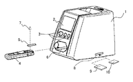
図1は本発明の第一の形態における測定装置の斜視図を示すものであり、図2は測定装置内部の電気回路基板を示す平面図である。以下に図1および図2の構成を説明する。図1において、測定装置1は表示部2と操作部3をもつ。4はアタッチメントであり、試験片5を装着した状態で、測定装置1の挿入部6に挿入される。試験片5には測定対象である血液などの検体7と反応する試薬(図示しない)が塗布されている。
(Embodiment 1)
FIG. 1 is a perspective view of a measuring apparatus according to the first embodiment of the present invention, and FIG. 2 is a plan view showing an electric circuit board inside the measuring apparatus. The configuration of FIGS. 1 and 2 will be described below. In FIG. 1, the measuring apparatus 1 has a display unit 2 and an operation unit 3. Reference numeral 4 denotes an attachment, which is inserted into the
試験片5の所定の位置に血液などの検体を点着後、アタッチメント4に試験片5を装着し、測定装置1の挿入部6から挿入すると、試験片5を装着したアタッチメント4は、測定装置1内部の所定の位置まで引き込まれ、その特性が測定される。測定方法は、例えば試験片5に光源(図示しない)からレーザ光を照射し、試験片に塗布された試薬と検体の反応の結果による変化を捕らえることにより行われる。
After spotting a specimen such as blood on a predetermined position of the test piece 5, the test piece 5 is attached to the attachment 4 and inserted from the
メモリカード9には、試験片5における検体との反応のばらつきを補正するための較正データが格納されており、メモリカード10には、測定装置1内に記憶されたファームウェアを更新するプログラムが格納されている。基板11上にはメモリカード挿入口8に対向する位置にメモリカード装着手段12が設けられており、メモリカード9または10が選択的に装着される。
The
測定時には、較正データ用のメモリカード9が装着手段12に装着されている。従来例の場合と同様に、検体7は試験片5に点着され、アタッチメント4に装着された後、測定装置1内部へ引き込まれ、測定が行われる。測定値はメモリカード9に格納されている較正データによって補正される。
At the time of measurement, a
ファームウェア更新時には、更新ファームウェア用メモリカード10が装着手段12に装着される。更新はシステム起動後ファーム更新用のプログラムが動作し、メモリカード10に格納されているファームウェアが読み取られ、測定装置1に格納されているファームウェアに上書きされることにより行われる。
At the time of firmware update, the update
(実施の形態2)
次に本発明の第二の実施形態について説明する。図3は本発明の第二の実施の形態における測定装置内部の電気回路基板の概略を示す平面図である。他の構成要素については図1に示す第一の実施の形態と同一である。
(Embodiment 2)
Next, a second embodiment of the present invention will be described. FIG. 3 is a plan view showing an outline of an electric circuit board inside the measuring apparatus according to the second embodiment of the present invention. Other components are the same as those in the first embodiment shown in FIG.
以下に図3の構成を説明する。基板11上には、メモリカード挿入口8に対向する位置にメモリカード装着手段12が設けられている。13は測定装置1の作動状態を検体の特性を測定する測定モード、もしくはファームウェア更新するファームウェア更新モードに切り換えるためのスイッチであり、作動部13aが設けられている。メモリカード10には、メモリカード装着手段12に装着された際、スイッチ13の作動部13aを矢印A方向に付勢させるよう突起部10aが設けられている。
The configuration of FIG. 3 will be described below. On the
メモリカード装着手段12に較正データ用のメモリカード9が装着されている場合、スイッチ13は作動部13aに力が加わっていない状態にある。この場合測定装置1は測定モードで動作し、通常の測定動作が行われる。
When the
メモリカード装着手段12にファームウェア更新用のメモリカード10が装着されている場合、突起部10aによりスイッチ13の作動部13aが矢印A方向に付勢された状態になる。この場合、測定装置1は更新モードで動作し、ファームウェアの更新が行われる。
When the
なお較正データ用のメモリカード9に突起部を設け、ファームウェア更新用のメモリカード10に突起部を設けない構成としてもよいことは、言うまでもない。
Needless to say, the calibration
(実施の形態3)
次に本発明の第三の実施形態について説明する。図4は本発明の第三の実施の形態における測定装置のファームウェアの流れ図を示したものである。他の構成要素については図1および図2に示す第一の実施の形態と同一である。
(Embodiment 3)
Next, a third embodiment of the present invention will be described. FIG. 4 shows a flowchart of the firmware of the measuring apparatus according to the third embodiment of the present invention. Other components are the same as those of the first embodiment shown in FIGS.
測定装置1のファームウェアにはバージョンを示す識別子が格納されている。またファームウェア更新用のメモリカード10にもバージョンを示す識別子が格納されている。
The firmware of the measuring device 1 stores an identifier indicating the version. The firmware
図4に示すように、更新モードでの測定装置1の起動時に、測定装置1のファームウェアのバージョンと、ファームウェア更新用のメモリカード10のバージョンとを取得し、比較を行う。比較の結果、メモリカード10のバージョンの方が測定装置1のバージョンより新しい場合はファームウェア更新動作を行い、それ以外の場合は更新動作を行わない。
As shown in FIG. 4, when the measurement apparatus 1 is started in the update mode, the firmware version of the measurement apparatus 1 and the version of the
また図5に示すように、各々のバージョン取得時に表示部2に表示させ、その表示内容を確認した使用者が操作部3を既定の方法に従って操作した場合にのみ更新動作を行う構成にしても良い。 Further, as shown in FIG. 5, the display unit 2 is displayed when each version is acquired, and the updating operation is performed only when the user who confirms the display contents operates the operation unit 3 according to a predetermined method. good.
(実施の形態4)
次に本発明の第四の実施形態について説明する。図6は本発明の第四の実施の形態における測定装置のファームウェアの流れ図を示したものである。他の構成要素については図1および図2に示す第一の実施の形態と同一である。
(Embodiment 4)
Next, a fourth embodiment of the present invention will be described. FIG. 6 shows a flowchart of the firmware of the measuring apparatus according to the fourth embodiment of the present invention. Other components are the same as those of the first embodiment shown in FIGS.
測定装置1には装置の供給先を示す識別子が格納されており、供給先の仕様に応じた測定を行うファームウェアを持つ。較正データ用のメモリカード9にも測定装置の供給先を示す識別子が格納されている。
The measuring device 1 stores an identifier indicating the supply destination of the device, and has firmware for performing measurement according to the specification of the supply destination. An identifier indicating the supply destination of the measuring apparatus is also stored in the
測定装置や試験片の供給先(すなわち、ユーザへの販売会社など)毎に検査対象や測定レンジ等がそれぞれ異なる仕様となる場合には、工場では、測定装置1のハードウェアを変更せずに、そのファームウェアや試験片5上の試薬の仕様を変更することで、コストを抑え低価格で上記供給先に提供することができるようになる。こうしたとき、ユーザーが使用するにあたって、双方の組み合わせが異なると、すなわち、測定装置1に対して、所定の試験片5がセットされなければならない。 In the case where the inspection object, the measurement range, etc. have different specifications for each measuring device or test piece supply destination (ie, a sales company to the user), the factory does not change the hardware of the measuring device 1. By changing the firmware and the specifications of the reagent on the test piece 5, the cost can be reduced and the reagent can be provided to the supplier at a low price. In such a case, when the user uses them, if the combination of the two is different, that is, a predetermined test piece 5 must be set to the measuring apparatus 1.
そこで、図6に示すように、測定モードにおいて測定装置1を起動した時に格納されている供給先識別子と、較正データ用のメモリカード9に格納されている供給先識別子とを取得し比較を行う。比較の結果、双方の識別子が一致した場合にのみ測定動作を行い、それ以外の場合は測定動作を行わない。こうすることで、測定装置に対して所定の試験片が正しく組み合わされた場合にのみ測定が行われるため、常に正しい測定結果を得ることができる。
Therefore, as shown in FIG. 6, the supply destination identifier stored when the measurement apparatus 1 is started in the measurement mode and the supply destination identifier stored in the
なお、測定装置1には複数の供給先を示す識別子を格納し、較正データ用のメモリカード9には、単独の供給先を示す識別子を格納しておき、比較の結果メモリカード9の識別子が測定器1に格納されている識別子のいずれかと一致した場合にのみ測定動作を行うよう構成しても良い。
The measuring device 1 stores identifiers indicating a plurality of supply destinations, the calibration
本発明にかかる測定装置は、試験片ごとの測定データの較正や測定装置のファームウェア更新をメモリカードのみ接続するだけの、安価なシステム構成で実現でき、また、試験片毎のデータの較正についても、ユーザーの操作ミスを防止し、正確な測定を実現することができるものであり、検体を試験片に適用し、試験片における検査対象物との呈色反応などから、その濃度等を計測する測定装置等に有用である。 The measuring device according to the present invention can be realized with an inexpensive system configuration in which only the memory card is connected to calibrate the measurement data for each test piece and update the firmware of the measurement device. Also, the calibration of the data for each test piece can be performed. It is possible to prevent user's operation mistakes and realize accurate measurement, apply the sample to the test piece, and measure the concentration etc. from the color reaction with the test object in the test piece. Useful for measuring devices.
1 測定装置
2 表示部
3 操作部
4 アタッチメント
5 試験片
6 アタッチメント挿入部
7 検体
8 メモリカード挿入口
9 較正データ用のメモリカード
10 更新ファームウェア用のメモリカード
10a 突起部
11 基板
12 メモリカード装着手段
13 スイッチ
13a スイッチ作動部
DESCRIPTION OF SYMBOLS 1 Measuring apparatus 2 Display part 3 Operation part 4 Attachment 5
Claims (10)
前記測定装置は、前記試験片の製造ロット毎に異なる特性を較正するための較正データを記憶した第1のメモリカードと、前記ファームウェアを更新すべきプログラムを記憶した第2のメモリカードとが、測定装置本体に共通して設けたコネクタに択一的に接続される構成としたことを特徴とする測定装置。 In order to display a series of measurement firmware and various information related to the measurement to the user in order to measure the reaction of the test object on the test piece in a detachable manner. In a measuring apparatus provided with a display means and an operation means for a user to perform a measurement operation,
The measurement apparatus includes a first memory card that stores calibration data for calibrating different characteristics for each production lot of the test piece, and a second memory card that stores a program for updating the firmware. A measuring apparatus characterized in that it is configured to be alternatively connected to a connector provided in common in the measuring apparatus main body.
The measurement apparatus according to claim 9, wherein the measurement apparatus collates the identification information of the first memory card prior to measurement, and performs the measurement operation only when the content is predetermined.
Priority Applications (1)
| Application Number | Priority Date | Filing Date | Title |
|---|---|---|---|
| JP2003272281A JP2005030983A (en) | 2003-07-09 | 2003-07-09 | measuring device |
Applications Claiming Priority (1)
| Application Number | Priority Date | Filing Date | Title |
|---|---|---|---|
| JP2003272281A JP2005030983A (en) | 2003-07-09 | 2003-07-09 | measuring device |
Publications (1)
| Publication Number | Publication Date |
|---|---|
| JP2005030983A true JP2005030983A (en) | 2005-02-03 |
Family
ID=34209888
Family Applications (1)
| Application Number | Title | Priority Date | Filing Date |
|---|---|---|---|
| JP2003272281A Pending JP2005030983A (en) | 2003-07-09 | 2003-07-09 | measuring device |
Country Status (1)
| Country | Link |
|---|---|
| JP (1) | JP2005030983A (en) |
Cited By (15)
| Publication number | Priority date | Publication date | Assignee | Title |
|---|---|---|---|---|
| JP2008537128A (en) * | 2005-05-17 | 2008-09-11 | エフ.ホフマン−ラ ロシュ アーゲー | HOST DEVICE AND METHOD FOR PROVIDING CALIBRATION INFORMATION AND REAGENT INFORMATION TO MEASURING DEVICE USING CONSUMABLE REAGENT IN MEASUREMENT PROCESS |
| JP2008249590A (en) * | 2007-03-30 | 2008-10-16 | Sysmex Corp | System, apparatus and method for managing set information, and backup program and storage medium therefor |
| JP2010042102A (en) * | 2008-08-11 | 2010-02-25 | Omron Healthcare Co Ltd | Biological information monitor, function switching method in biological information monitor, and display method in biological information monitor |
| JP2013152241A (en) * | 2007-06-15 | 2013-08-08 | F Hoffmann-La Roche Ag | System for measuring analyte concentration in body fluid sample |
| JP2015042954A (en) * | 2013-08-26 | 2015-03-05 | ウシオ電機株式会社 | Reagent kit and software server for measurement |
| JP2015155922A (en) * | 2006-05-10 | 2015-08-27 | セラノス, インコーポレイテッド | Real-time detection of influenza virus |
| JP2020514752A (en) * | 2017-03-17 | 2020-05-21 | アイセンサー・カンパニー・リミテッドIxensor Co., Ltd. | Methods for improving usability and accuracy of physiological measurements |
| US10761030B2 (en) | 2005-05-09 | 2020-09-01 | Labrador Diagnostics Llc | System and methods for analyte detection |
| US10876956B2 (en) | 2011-01-21 | 2020-12-29 | Labrador Diagnostics Llc | Systems and methods for sample use maximization |
| US10900958B2 (en) | 2007-10-02 | 2021-01-26 | Labrador Diagnostics Llc | Modular point-of-care devices, systems, and uses thereof |
| US11139084B2 (en) | 2009-10-19 | 2021-10-05 | Labrador Diagnostics Llc | Integrated health data capture and analysis system |
| US11215610B2 (en) | 2006-10-13 | 2022-01-04 | Labrador Diagnostics Llc | Reducing optical interference in a fluidic device |
| US11287421B2 (en) | 2006-03-24 | 2022-03-29 | Labrador Diagnostics Llc | Systems and methods of sample processing and fluid control in a fluidic system |
| US11754554B2 (en) | 2007-08-06 | 2023-09-12 | Labrador Diagnostics Llc | Systems and methods of fluidic sample processing |
| US11802882B2 (en) | 2006-11-14 | 2023-10-31 | Labrador Diagnostics Llc | Methods for the detection of analytes in small-volume blood samples |
-
2003
- 2003-07-09 JP JP2003272281A patent/JP2005030983A/en active Pending
Cited By (34)
| Publication number | Priority date | Publication date | Assignee | Title |
|---|---|---|---|---|
| US10761030B2 (en) | 2005-05-09 | 2020-09-01 | Labrador Diagnostics Llc | System and methods for analyte detection |
| US11630069B2 (en) | 2005-05-09 | 2023-04-18 | Labrador Diagnostics Llc | Fluidic medical devices and uses thereof |
| US10908093B2 (en) | 2005-05-09 | 2021-02-02 | Labrador Diagnostics, LLC | Calibration of fluidic devices |
| JP2008537128A (en) * | 2005-05-17 | 2008-09-11 | エフ.ホフマン−ラ ロシュ アーゲー | HOST DEVICE AND METHOD FOR PROVIDING CALIBRATION INFORMATION AND REAGENT INFORMATION TO MEASURING DEVICE USING CONSUMABLE REAGENT IN MEASUREMENT PROCESS |
| US11287421B2 (en) | 2006-03-24 | 2022-03-29 | Labrador Diagnostics Llc | Systems and methods of sample processing and fluid control in a fluidic system |
| US11162947B2 (en) | 2006-05-10 | 2021-11-02 | Labrador Diagnostics Llc | Real-time detection of influenza virus |
| JP2015155922A (en) * | 2006-05-10 | 2015-08-27 | セラノス, インコーポレイテッド | Real-time detection of influenza virus |
| JP2017194486A (en) * | 2006-05-10 | 2017-10-26 | セラノス, インコーポレイテッド | Influenza virus real-time detection |
| US9885715B2 (en) | 2006-05-10 | 2018-02-06 | Theranos IP Comany, LLC | Real-time detection of influenza virus |
| JP2019144268A (en) * | 2006-05-10 | 2019-08-29 | セラノス アイピー カンパニー エルエルシー | Influenza virus real-time detection |
| US11215610B2 (en) | 2006-10-13 | 2022-01-04 | Labrador Diagnostics Llc | Reducing optical interference in a fluidic device |
| US11442061B2 (en) | 2006-10-13 | 2022-09-13 | Labrador Diagnostics Llc | Reducing optical interference in a fluidic device |
| US11802882B2 (en) | 2006-11-14 | 2023-10-31 | Labrador Diagnostics Llc | Methods for the detection of analytes in small-volume blood samples |
| JP2008249590A (en) * | 2007-03-30 | 2008-10-16 | Sysmex Corp | System, apparatus and method for managing set information, and backup program and storage medium therefor |
| JP2013152241A (en) * | 2007-06-15 | 2013-08-08 | F Hoffmann-La Roche Ag | System for measuring analyte concentration in body fluid sample |
| US11754554B2 (en) | 2007-08-06 | 2023-09-12 | Labrador Diagnostics Llc | Systems and methods of fluidic sample processing |
| US11366106B2 (en) | 2007-10-02 | 2022-06-21 | Labrador Diagnostics Llc | Modular point-of-care devices, systems, and uses thereof |
| US11143647B2 (en) | 2007-10-02 | 2021-10-12 | Labrador Diagnostics, LLC | Modular point-of-care devices, systems, and uses thereof |
| US11899010B2 (en) | 2007-10-02 | 2024-02-13 | Labrador Diagnostics Llc | Modular point-of-care devices, systems, and uses thereof |
| US10900958B2 (en) | 2007-10-02 | 2021-01-26 | Labrador Diagnostics Llc | Modular point-of-care devices, systems, and uses thereof |
| US11061022B2 (en) | 2007-10-02 | 2021-07-13 | Labrador Diagnostics Llc | Modular point-of-care devices, systems, and uses thereof |
| US11092593B2 (en) | 2007-10-02 | 2021-08-17 | Labrador Diagnostics Llc | Modular point-of-care devices, systems, and uses thereof |
| US11199538B2 (en) | 2007-10-02 | 2021-12-14 | Labrador Diagnostics Llc | Modular point-of-care devices, systems, and uses thereof |
| US11137391B2 (en) | 2007-10-02 | 2021-10-05 | Labrador Diagnostics Llc | Modular point-of-care devices, systems, and uses thereof |
| JP2010042102A (en) * | 2008-08-11 | 2010-02-25 | Omron Healthcare Co Ltd | Biological information monitor, function switching method in biological information monitor, and display method in biological information monitor |
| US11195624B2 (en) | 2009-10-19 | 2021-12-07 | Labrador Diagnostics Llc | Integrated health data capture and analysis system |
| US11139084B2 (en) | 2009-10-19 | 2021-10-05 | Labrador Diagnostics Llc | Integrated health data capture and analysis system |
| US11158429B2 (en) | 2009-10-19 | 2021-10-26 | Labrador Diagnostics Llc | Integrated health data capture and analysis system |
| US11199489B2 (en) | 2011-01-20 | 2021-12-14 | Labrador Diagnostics Llc | Systems and methods for sample use maximization |
| US10876956B2 (en) | 2011-01-21 | 2020-12-29 | Labrador Diagnostics Llc | Systems and methods for sample use maximization |
| US11644410B2 (en) | 2011-01-21 | 2023-05-09 | Labrador Diagnostics Llc | Systems and methods for sample use maximization |
| JP2015042954A (en) * | 2013-08-26 | 2015-03-05 | ウシオ電機株式会社 | Reagent kit and software server for measurement |
| JP2020514752A (en) * | 2017-03-17 | 2020-05-21 | アイセンサー・カンパニー・リミテッドIxensor Co., Ltd. | Methods for improving usability and accuracy of physiological measurements |
| US11940388B2 (en) | 2017-03-17 | 2024-03-26 | Ixensor Co., Ltd. | Method for improving usability and accuracy for physiological measurement |
Similar Documents
| Publication | Publication Date | Title |
|---|---|---|
| JP2005030983A (en) | measuring device | |
| US12061185B1 (en) | Replaceable alcohol sensor module | |
| US9075030B2 (en) | Automatic analyzer | |
| JPS6138464A (en) | Automatic chemical analyser | |
| US20090223287A1 (en) | Bio-Monitoring System and Methods of Use Thereof | |
| KR19980032318A (en) | Method and apparatus for calibrating a sensor element | |
| US20100015006A1 (en) | Test strip with identification openings and test instrument using the same | |
| JP3500295B2 (en) | Sample processing system | |
| JP2000111506A (en) | Measuring device with memory | |
| US20030204313A1 (en) | Biosensing meter | |
| CN108139343A (en) | Replaceable alcohol sensor module | |
| JP2001356108A (en) | Biosensor | |
| JPH10253572A (en) | Measuring device with electrodes with memory | |
| JP2010127786A (en) | Analysis apparatus and sensor container | |
| US9329167B2 (en) | Replaceable alcohol sensor module | |
| US11517231B2 (en) | Blood glucose test strip and associated measuring method | |
| US20060157549A1 (en) | Smart cards for automated sample analysis devices | |
| US20060145885A1 (en) | Multi-function meter | |
| CN102183570A (en) | Implementation method and detector for improving blood detection accuracy | |
| US20240175718A1 (en) | Sensing system | |
| EP1967838A1 (en) | Detecting sensor, and density measuring device | |
| JP4611467B2 (en) | Diagnosis support system | |
| JP4313839B1 (en) | Terminal for judging urinalysis results | |
| CN101900704A (en) | Method for improving blood measuring accuracy by insertion algorithm | |
| CN201542616U (en) | Detection device |