JP2004533275A - Apparatus and method for controlling delivery from a drug delivery device - Google Patents
Apparatus and method for controlling delivery from a drug delivery device Download PDFInfo
- Publication number
- JP2004533275A JP2004533275A JP2002545769A JP2002545769A JP2004533275A JP 2004533275 A JP2004533275 A JP 2004533275A JP 2002545769 A JP2002545769 A JP 2002545769A JP 2002545769 A JP2002545769 A JP 2002545769A JP 2004533275 A JP2004533275 A JP 2004533275A
- Authority
- JP
- Japan
- Prior art keywords
- plug
- reservoir
- channel
- drug delivery
- outlet
- Prior art date
- Legal status (The legal status is an assumption and is not a legal conclusion. Google has not performed a legal analysis and makes no representation as to the accuracy of the status listed.)
- Granted
Links
- 238000012377 drug delivery Methods 0.000 title claims abstract description 113
- 238000000034 method Methods 0.000 title claims description 19
- 238000009472 formulation Methods 0.000 claims abstract description 110
- 239000000203 mixture Substances 0.000 claims abstract description 110
- 239000003814 drug Substances 0.000 claims abstract description 93
- 229940079593 drug Drugs 0.000 claims abstract description 88
- 239000000463 material Substances 0.000 claims description 27
- 239000007788 liquid Substances 0.000 claims description 20
- 108090000765 processed proteins & peptides Proteins 0.000 claims description 6
- 230000009969 flowable effect Effects 0.000 claims description 4
- 239000005556 hormone Substances 0.000 claims description 4
- 229940088597 hormone Drugs 0.000 claims description 4
- 108020004707 nucleic acids Proteins 0.000 claims description 4
- 102000039446 nucleic acids Human genes 0.000 claims description 4
- 150000007523 nucleic acids Chemical class 0.000 claims description 4
- 102000004196 processed proteins & peptides Human genes 0.000 claims description 4
- 229920001184 polypeptide Polymers 0.000 claims description 3
- 238000002513 implantation Methods 0.000 description 12
- 230000008901 benefit Effects 0.000 description 10
- 238000009792 diffusion process Methods 0.000 description 9
- 239000000956 alloy Substances 0.000 description 8
- 229910045601 alloy Inorganic materials 0.000 description 8
- 238000003860 storage Methods 0.000 description 8
- RTAQQCXQSZGOHL-UHFFFAOYSA-N Titanium Chemical compound [Ti] RTAQQCXQSZGOHL-UHFFFAOYSA-N 0.000 description 7
- 229920000642 polymer Polymers 0.000 description 7
- 239000000126 substance Substances 0.000 description 7
- 239000010936 titanium Substances 0.000 description 7
- 229910052719 titanium Inorganic materials 0.000 description 7
- 238000003780 insertion Methods 0.000 description 6
- 230000037431 insertion Effects 0.000 description 6
- 238000002360 preparation method Methods 0.000 description 6
- NRTOMJZYCJJWKI-UHFFFAOYSA-N Titanium nitride Chemical compound [Ti]#N NRTOMJZYCJJWKI-UHFFFAOYSA-N 0.000 description 5
- 230000000694 effects Effects 0.000 description 5
- 239000012530 fluid Substances 0.000 description 5
- 229910052751 metal Inorganic materials 0.000 description 5
- 239000002184 metal Substances 0.000 description 5
- 230000003204 osmotic effect Effects 0.000 description 5
- -1 polytetrafluoroethylene Polymers 0.000 description 5
- XEEYBQQBJWHFJM-UHFFFAOYSA-N Iron Chemical compound [Fe] XEEYBQQBJWHFJM-UHFFFAOYSA-N 0.000 description 4
- 150000002739 metals Chemical class 0.000 description 4
- BASFCYQUMIYNBI-UHFFFAOYSA-N platinum Chemical compound [Pt] BASFCYQUMIYNBI-UHFFFAOYSA-N 0.000 description 4
- 230000008961 swelling Effects 0.000 description 4
- 230000001225 therapeutic effect Effects 0.000 description 4
- 239000013543 active substance Substances 0.000 description 3
- 230000036760 body temperature Effects 0.000 description 3
- 238000002512 chemotherapy Methods 0.000 description 3
- 201000010099 disease Diseases 0.000 description 3
- 208000037265 diseases, disorders, signs and symptoms Diseases 0.000 description 3
- 230000007613 environmental effect Effects 0.000 description 3
- PCHJSUWPFVWCPO-UHFFFAOYSA-N gold Chemical compound [Au] PCHJSUWPFVWCPO-UHFFFAOYSA-N 0.000 description 3
- 239000010931 gold Substances 0.000 description 3
- 229910052737 gold Inorganic materials 0.000 description 3
- 230000007062 hydrolysis Effects 0.000 description 3
- 238000006460 hydrolysis reaction Methods 0.000 description 3
- 239000010935 stainless steel Substances 0.000 description 3
- 229910001220 stainless steel Inorganic materials 0.000 description 3
- 229910052715 tantalum Inorganic materials 0.000 description 3
- GUVRBAGPIYLISA-UHFFFAOYSA-N tantalum atom Chemical compound [Ta] GUVRBAGPIYLISA-UHFFFAOYSA-N 0.000 description 3
- KAKZBPTYRLMSJV-UHFFFAOYSA-N Butadiene Chemical compound C=CC=C KAKZBPTYRLMSJV-UHFFFAOYSA-N 0.000 description 2
- 206010062016 Immunosuppression Diseases 0.000 description 2
- PPBRXRYQALVLMV-UHFFFAOYSA-N Styrene Chemical compound C=CC1=CC=CC=C1 PPBRXRYQALVLMV-UHFFFAOYSA-N 0.000 description 2
- 239000013011 aqueous formulation Substances 0.000 description 2
- 239000002327 cardiovascular agent Substances 0.000 description 2
- 229940125692 cardiovascular agent Drugs 0.000 description 2
- 229920002678 cellulose Polymers 0.000 description 2
- 239000001913 cellulose Substances 0.000 description 2
- 210000003169 central nervous system Anatomy 0.000 description 2
- 239000003795 chemical substances by application Substances 0.000 description 2
- 150000001875 compounds Chemical class 0.000 description 2
- 229920001971 elastomer Polymers 0.000 description 2
- 239000003792 electrolyte Substances 0.000 description 2
- 238000002474 experimental method Methods 0.000 description 2
- 230000004907 flux Effects 0.000 description 2
- 230000006870 function Effects 0.000 description 2
- 239000003667 hormone antagonist Substances 0.000 description 2
- 230000001506 immunosuppresive effect Effects 0.000 description 2
- 238000001802 infusion Methods 0.000 description 2
- 239000007924 injection Substances 0.000 description 2
- 238000002347 injection Methods 0.000 description 2
- 229910052742 iron Inorganic materials 0.000 description 2
- 230000003907 kidney function Effects 0.000 description 2
- 239000012669 liquid formulation Substances 0.000 description 2
- 230000007774 longterm Effects 0.000 description 2
- 238000004519 manufacturing process Methods 0.000 description 2
- 230000007246 mechanism Effects 0.000 description 2
- 230000004060 metabolic process Effects 0.000 description 2
- 230000001613 neoplastic effect Effects 0.000 description 2
- 229910052697 platinum Inorganic materials 0.000 description 2
- 229920000515 polycarbonate Polymers 0.000 description 2
- 239000004417 polycarbonate Substances 0.000 description 2
- 108090000623 proteins and genes Proteins 0.000 description 2
- 230000000717 retained effect Effects 0.000 description 2
- 230000002123 temporal effect Effects 0.000 description 2
- 229940124597 therapeutic agent Drugs 0.000 description 2
- 238000012546 transfer Methods 0.000 description 2
- XLYOFNOQVPJJNP-UHFFFAOYSA-N water Substances O XLYOFNOQVPJJNP-UHFFFAOYSA-N 0.000 description 2
- NLHHRLWOUZZQLW-UHFFFAOYSA-N Acrylonitrile Chemical compound C=CC#N NLHHRLWOUZZQLW-UHFFFAOYSA-N 0.000 description 1
- 229910000684 Cobalt-chrome Inorganic materials 0.000 description 1
- 241000282326 Felis catus Species 0.000 description 1
- 206010061218 Inflammation Diseases 0.000 description 1
- 102000004310 Ion Channels Human genes 0.000 description 1
- 241000124008 Mammalia Species 0.000 description 1
- 208000030852 Parasitic disease Diseases 0.000 description 1
- 239000004698 Polyethylene Substances 0.000 description 1
- 239000004642 Polyimide Substances 0.000 description 1
- 239000004743 Polypropylene Substances 0.000 description 1
- 239000004793 Polystyrene Substances 0.000 description 1
- 229910001069 Ti alloy Inorganic materials 0.000 description 1
- 230000002159 abnormal effect Effects 0.000 description 1
- 229920006243 acrylic copolymer Polymers 0.000 description 1
- XECAHXYUAAWDEL-UHFFFAOYSA-N acrylonitrile butadiene styrene Chemical compound C=CC=C.C=CC#N.C=CC1=CC=CC=C1 XECAHXYUAAWDEL-UHFFFAOYSA-N 0.000 description 1
- 229920000122 acrylonitrile butadiene styrene Polymers 0.000 description 1
- 239000004676 acrylonitrile butadiene styrene Substances 0.000 description 1
- 239000000853 adhesive Substances 0.000 description 1
- 238000004026 adhesive bonding Methods 0.000 description 1
- 230000001070 adhesive effect Effects 0.000 description 1
- 230000002411 adverse Effects 0.000 description 1
- 229940035676 analgesics Drugs 0.000 description 1
- 239000000730 antalgic agent Substances 0.000 description 1
- 239000002260 anti-inflammatory agent Substances 0.000 description 1
- 229940121363 anti-inflammatory agent Drugs 0.000 description 1
- 239000002246 antineoplastic agent Substances 0.000 description 1
- 238000005842 biochemical reaction Methods 0.000 description 1
- 230000033228 biological regulation Effects 0.000 description 1
- 230000009172 bursting Effects 0.000 description 1
- 230000000747 cardiac effect Effects 0.000 description 1
- 238000005266 casting Methods 0.000 description 1
- 239000000919 ceramic Substances 0.000 description 1
- 238000006243 chemical reaction Methods 0.000 description 1
- 238000004140 cleaning Methods 0.000 description 1
- 239000010952 cobalt-chrome Substances 0.000 description 1
- 229920000891 common polymer Polymers 0.000 description 1
- 238000011109 contamination Methods 0.000 description 1
- 239000000599 controlled substance Substances 0.000 description 1
- 230000001276 controlling effect Effects 0.000 description 1
- 229920001577 copolymer Polymers 0.000 description 1
- 238000005336 cracking Methods 0.000 description 1
- 229940127089 cytotoxic agent Drugs 0.000 description 1
- 230000001687 destabilization Effects 0.000 description 1
- 238000011161 development Methods 0.000 description 1
- 238000010586 diagram Methods 0.000 description 1
- 239000003085 diluting agent Substances 0.000 description 1
- 238000010790 dilution Methods 0.000 description 1
- 239000012895 dilution Substances 0.000 description 1
- 238000007599 discharging Methods 0.000 description 1
- 229940126534 drug product Drugs 0.000 description 1
- 238000002651 drug therapy Methods 0.000 description 1
- 230000002124 endocrine Effects 0.000 description 1
- 230000003628 erosive effect Effects 0.000 description 1
- 230000007661 gastrointestinal function Effects 0.000 description 1
- 210000001035 gastrointestinal tract Anatomy 0.000 description 1
- 239000011521 glass Substances 0.000 description 1
- 239000007943 implant Substances 0.000 description 1
- 230000002757 inflammatory effect Effects 0.000 description 1
- 230000004054 inflammatory process Effects 0.000 description 1
- 230000000977 initiatory effect Effects 0.000 description 1
- 238000001361 intraarterial administration Methods 0.000 description 1
- 238000007918 intramuscular administration Methods 0.000 description 1
- 238000001990 intravenous administration Methods 0.000 description 1
- 150000002500 ions Chemical class 0.000 description 1
- 230000000302 ischemic effect Effects 0.000 description 1
- 230000010534 mechanism of action Effects 0.000 description 1
- 239000007769 metal material Substances 0.000 description 1
- 230000000813 microbial effect Effects 0.000 description 1
- 230000005012 migration Effects 0.000 description 1
- 238000013508 migration Methods 0.000 description 1
- 230000004899 motility Effects 0.000 description 1
- 229940005483 opioid analgesics Drugs 0.000 description 1
- 210000000056 organ Anatomy 0.000 description 1
- 230000035515 penetration Effects 0.000 description 1
- 239000000825 pharmaceutical preparation Substances 0.000 description 1
- 230000000144 pharmacologic effect Effects 0.000 description 1
- 230000000704 physical effect Effects 0.000 description 1
- 239000002504 physiological saline solution Substances 0.000 description 1
- 239000004033 plastic Substances 0.000 description 1
- 229920003023 plastic Polymers 0.000 description 1
- 229920002493 poly(chlorotrifluoroethylene) Polymers 0.000 description 1
- 229920002492 poly(sulfone) Polymers 0.000 description 1
- 229920002239 polyacrylonitrile Polymers 0.000 description 1
- 239000005023 polychlorotrifluoroethylene (PCTFE) polymer Substances 0.000 description 1
- 229920000573 polyethylene Polymers 0.000 description 1
- 229920001721 polyimide Polymers 0.000 description 1
- 229920001155 polypropylene Polymers 0.000 description 1
- 229920002223 polystyrene Polymers 0.000 description 1
- 229920001343 polytetrafluoroethylene Polymers 0.000 description 1
- 239000004810 polytetrafluoroethylene Substances 0.000 description 1
- 229920002635 polyurethane Polymers 0.000 description 1
- 239000004814 polyurethane Substances 0.000 description 1
- 239000004800 polyvinyl chloride Substances 0.000 description 1
- 229920000915 polyvinyl chloride Polymers 0.000 description 1
- 239000011148 porous material Substances 0.000 description 1
- 238000003825 pressing Methods 0.000 description 1
- 230000002265 prevention Effects 0.000 description 1
- 230000008569 process Effects 0.000 description 1
- 230000000541 pulsatile effect Effects 0.000 description 1
- 238000010926 purge Methods 0.000 description 1
- 229920013730 reactive polymer Polymers 0.000 description 1
- 238000010992 reflux Methods 0.000 description 1
- 230000001105 regulatory effect Effects 0.000 description 1
- 150000003839 salts Chemical class 0.000 description 1
- 239000007787 solid Substances 0.000 description 1
- 238000007920 subcutaneous administration Methods 0.000 description 1
- 230000000946 synaptic effect Effects 0.000 description 1
- 230000001839 systemic circulation Effects 0.000 description 1
- 231100000027 toxicology Toxicity 0.000 description 1
- 210000005166 vasculature Anatomy 0.000 description 1
- 239000011782 vitamin Substances 0.000 description 1
- 229940088594 vitamin Drugs 0.000 description 1
- 229930003231 vitamin Natural products 0.000 description 1
- 235000013343 vitamin Nutrition 0.000 description 1
- 238000005406 washing Methods 0.000 description 1
- 238000003466 welding Methods 0.000 description 1
- 238000009736 wetting Methods 0.000 description 1
Images


Classifications
-
- A—HUMAN NECESSITIES
- A61—MEDICAL OR VETERINARY SCIENCE; HYGIENE
- A61M—DEVICES FOR INTRODUCING MEDIA INTO, OR ONTO, THE BODY; DEVICES FOR TRANSDUCING BODY MEDIA OR FOR TAKING MEDIA FROM THE BODY; DEVICES FOR PRODUCING OR ENDING SLEEP OR STUPOR
- A61M5/00—Devices for bringing media into the body in a subcutaneous, intra-vascular or intramuscular way; Accessories therefor, e.g. filling or cleaning devices, arm-rests
- A61M5/14—Infusion devices, e.g. infusing by gravity; Blood infusion; Accessories therefor
- A61M5/142—Pressure infusion, e.g. using pumps
- A61M5/14244—Pressure infusion, e.g. using pumps adapted to be carried by the patient, e.g. portable on the body
- A61M5/14276—Pressure infusion, e.g. using pumps adapted to be carried by the patient, e.g. portable on the body specially adapted for implantation
-
- A—HUMAN NECESSITIES
- A61—MEDICAL OR VETERINARY SCIENCE; HYGIENE
- A61K—PREPARATIONS FOR MEDICAL, DENTAL OR TOILETRY PURPOSES
- A61K9/00—Medicinal preparations characterised by special physical form
- A61K9/0002—Galenical forms characterised by the drug release technique; Application systems commanded by energy
- A61K9/0004—Osmotic delivery systems; Sustained release driven by osmosis, thermal energy or gas
-
- A—HUMAN NECESSITIES
- A61—MEDICAL OR VETERINARY SCIENCE; HYGIENE
- A61M—DEVICES FOR INTRODUCING MEDIA INTO, OR ONTO, THE BODY; DEVICES FOR TRANSDUCING BODY MEDIA OR FOR TAKING MEDIA FROM THE BODY; DEVICES FOR PRODUCING OR ENDING SLEEP OR STUPOR
- A61M2205/00—General characteristics of the apparatus
- A61M2205/02—General characteristics of the apparatus characterised by a particular materials
- A61M2205/0272—Electro-active or magneto-active materials
- A61M2205/0294—Piezoelectric materials
-
- A—HUMAN NECESSITIES
- A61—MEDICAL OR VETERINARY SCIENCE; HYGIENE
- A61M—DEVICES FOR INTRODUCING MEDIA INTO, OR ONTO, THE BODY; DEVICES FOR TRANSDUCING BODY MEDIA OR FOR TAKING MEDIA FROM THE BODY; DEVICES FOR PRODUCING OR ENDING SLEEP OR STUPOR
- A61M31/00—Devices for introducing or retaining media, e.g. remedies, in cavities of the body
- A61M31/002—Devices for releasing a drug at a continuous and controlled rate for a prolonged period of time
-
- A—HUMAN NECESSITIES
- A61—MEDICAL OR VETERINARY SCIENCE; HYGIENE
- A61M—DEVICES FOR INTRODUCING MEDIA INTO, OR ONTO, THE BODY; DEVICES FOR TRANSDUCING BODY MEDIA OR FOR TAKING MEDIA FROM THE BODY; DEVICES FOR PRODUCING OR ENDING SLEEP OR STUPOR
- A61M5/00—Devices for bringing media into the body in a subcutaneous, intra-vascular or intramuscular way; Accessories therefor, e.g. filling or cleaning devices, arm-rests
- A61M5/14—Infusion devices, e.g. infusing by gravity; Blood infusion; Accessories therefor
- A61M5/168—Means for controlling media flow to the body or for metering media to the body, e.g. drip meters, counters ; Monitoring media flow to the body
- A61M5/16804—Flow controllers
-
- A—HUMAN NECESSITIES
- A61—MEDICAL OR VETERINARY SCIENCE; HYGIENE
- A61M—DEVICES FOR INTRODUCING MEDIA INTO, OR ONTO, THE BODY; DEVICES FOR TRANSDUCING BODY MEDIA OR FOR TAKING MEDIA FROM THE BODY; DEVICES FOR PRODUCING OR ENDING SLEEP OR STUPOR
- A61M5/00—Devices for bringing media into the body in a subcutaneous, intra-vascular or intramuscular way; Accessories therefor, e.g. filling or cleaning devices, arm-rests
- A61M5/36—Devices for bringing media into the body in a subcutaneous, intra-vascular or intramuscular way; Accessories therefor, e.g. filling or cleaning devices, arm-rests with means for eliminating or preventing injection or infusion of air into body
Landscapes
- Health & Medical Sciences (AREA)
- Life Sciences & Earth Sciences (AREA)
- Veterinary Medicine (AREA)
- Public Health (AREA)
- Engineering & Computer Science (AREA)
- General Health & Medical Sciences (AREA)
- Animal Behavior & Ethology (AREA)
- Medicinal Chemistry (AREA)
- Epidemiology (AREA)
- Pharmacology & Pharmacy (AREA)
- Chemical & Material Sciences (AREA)
- Bioinformatics & Cheminformatics (AREA)
- Vascular Medicine (AREA)
- Anesthesiology (AREA)
- Biomedical Technology (AREA)
- Heart & Thoracic Surgery (AREA)
- Hematology (AREA)
- Infusion, Injection, And Reservoir Apparatuses (AREA)
- Medicines That Contain Protein Lipid Enzymes And Other Medicines (AREA)
Abstract
本発明は、薬物送達装置とともに使用されるプラグであって、排出チャンネルと、薬物送達装置リザーバ内の製剤の熱膨張に対応する膨張制御チャンネルとを規定するプラグを特徴とする。ひとつの態様において、プラグは、トラップされた空気の放出を容易にし且つ密閉された薬物リザーバからの製剤の熱膨張に対応するための膨張制御チャンネルを規定する、内側プラグ部品と外側プラグ部品とを含む。プラグはさらに排出チャンネルを規定する。プラグは、選択的に、送達口直前の流路内に位置するフリットをさらに含んでいてもよい。またはその両方であってもよい。The invention features a plug for use with a drug delivery device, the plug defining a discharge channel and an expansion control channel that accommodates thermal expansion of the formulation in the drug delivery device reservoir. In one embodiment, the plug includes an inner plug component and an outer plug component that define an expansion control channel that facilitates the release of trapped air and accommodates thermal expansion of the formulation from the sealed drug reservoir. Including. The plug further defines an outlet channel. The plug may optionally further include a frit located in the flow path immediately before the delivery port. Or both may be used.
Description
【技術分野】
【0001】
発明の分野
本発明は、薬物送達の制御を容易にするための装置および方法に関する。
【背景技術】
【0002】
発明の背景
埋植可能な薬物送達装置は、種々の症状および疾患を治療するうえで、治療が長期間に及ぶ場合は特に、優れた治療用ツールとなる。埋植可能な薬物送達装置は、薬品の複数回投与に付随しうる不便さおよび苦痛を回避し、さらには、例えば、ボーラス投与を避け(例えば、非経口的な注射投与とは対照的に)、かつ患者の服薬遵守を高めることによって、治療上の利益を向上させる。薬物送達の精密な制御に資する装置では、予測可能でかつ信頼性のある投与量と速度とで薬物を送達できる(例えば、装置が埋植されている環境に左右されない)ため、こうした装置に対する関心は特に高い。
【0003】
埋植可能な薬物送達装置は種々開発されており、こうした装置は、種々の異なる機序に基づいてリザーバから投与対象の治療部位への薬物の移動を実現している。一般的に、こうした送達技術は、例えば拡散機序、浸食機序、または対流機序に基づいていてもよい。対流システムに基づく薬物送達装置は、一般的に、装置への補充が可能であること、および治療部位に薬物を局所的に送達させるためのカテーテルとの併用に適合性があることなどの利点があるため、当該分野において特に関心が高い。典型的な対流システムには、電気機械式ポンプ、浸透ポンプ、電気浸透ポンプ、電気化学的ポンプ、加水分解システム、圧電ポンプ、ゴム弾性ポンプ、蒸気圧ポンプ、および電解ポンプが含まれるが、これらに限定されることはない。
【0004】
埋植可能な装置の開発においては、特に薬物の送達制御に関して、薬物送達の分野でいくつかの課題が生じた。このような課題の1つとして、始動時点(例えば、薬物送達装置の埋植直後)から薬物送達を正確に制御できる能力がある。例えば、保管中および埋植後の環境温度の変化によって、製剤が膨張および収縮する可能性があり、このことは、埋植後の製剤の送達量に影響を与える可能性がある。埋植後に製剤が膨張すると、少量の製剤が非制御下に放出される「過剰投与」となる可能性があり、このことは、高濃縮の薬剤を使用する場合は特に問題となる。環境温度の変化はまた、リザーバ内またはリザーバと流出口との間にトラップされた空気を膨張および収縮させる可能性があり、このこともまた、薬物送達開始時の制御能力に悪影響を与える可能性がある。さらに、送達開始時に製剤の流れが「分裂する」可能性がある。これは、製剤が実質的な連続流になっておらず、気泡またはガス気泡(例えば、「バースト」)によって分離された1つ以上の不連続な部分を製剤の本流の前に有しているという現象である。結果として、始動時には、製剤が正確に制御されずに送達される可能性がある。
【0005】
これらの問題を解決する1つの方法は、製剤が膨張状態にあっても流れを調節できるよう、リザーバから出た製剤が通過するチャンネルを十分小さくすることである。しかし、流れを調節できるだけの小さなチャンネルは一般的に、許容できないほど長い(且つ、例えば、始動時に許容できないほど送達を遅延させる)か、または、容積が不十分なため熱膨張に対応できず、したがってリザーバから製剤が漏出する原因となり得る。リザーバからの内容物の損失をきたさずに製剤の膨張(例えば、保管中および埋植後の環境温度の変化による膨張)を許容できるような方式で、薬物送達装置の製造中にリザーバを正確に充填することは非常に困難であることが周知となっている。
【0006】
上述から明らかなように、薬物送達装置、特に対流式の薬物送達装置と併用でき、且つ、薬物送達開始時の問題を回避できる装置が必要とされている。本発明はこの問題を解決するものである。
【発明の開示】
【0007】
発明の概要
本発明は、薬物送達装置とともに使用されるプラグであって、このプラグは排出チャンネルと、薬物送達装置リザーバ内の製剤の熱膨張に対応する膨張制御チャンネルとを規定する。ひとつの態様において、プラグは、トラップされた空気の放出を容易にし且つ密閉された薬物リザーバからの製剤の熱膨張に対応するための膨張制御チャンネルを規定する、内側プラグ部品と外側プラグ部品とを含む。プラグはさらに排出チャンネルを規定し、また、任意選択的に、送達口直前の流路内に位置するフリットをさらに含んでいてもよい。またはその両方であってもよい。
【0008】
ひとつの局面において、本発明は、内側プラグ部品と該内側プラグ部品を収容するよう適合された外側プラグ部品とを含むプラグであって、流入口、膨張制御チャンネル、および流出口を規定するプラグを特徴とする。該プラグの流入口、膨張制御チャンネル、および流出口は、プラグの内および外の流路を規定する。ひとつの態様では、膨張制御チャンネルの少なくとも一部分が、内側プラグ部品本体を通る通路を規定する。別の態様では、内側プラグ部品は膨張制御チャンネル内を滑動できる。関連する態様においては、滑動可能な内側プラグ部品が外側プラグ部品内に収容されるよう、膨張制御チャンネルは外側プラグ部品によって規定される。関連する別の態様において、膨張制御チャンネルは内側プラグ部品と外側プラグ部品との隣接端、および薬物送達装置のリザーバ本体の内壁によって規定される。
【0009】
本発明は、別の局面において、本発明のプラグを含む薬物送達装置に関する。ひとつの態様において、該薬物送達装置は埋植可能である。
【0010】
さらに別の局面において、本発明は、本発明のプラグを含む薬物送達装置を使用した薬物送達の方法に関する。ひとつの態様において、該薬物送達装置は埋植可能である。
【0011】
本発明の主たる目的は、(例えば、保管中の製剤の熱膨張による)製剤の漏出、始動時の製剤のバーストまたはボーラス投与など、従来の装置に伴う問題を回避しつつ薬物送達を制御することである。
【0012】
本発明の利点の1つは、リザーバ内の流体の熱膨張による影響を抑制するのに役立つ流出経路を維持したまま正確にリザーバに充填できることである。
【0013】
本発明の重要な利点の1つは、環境温度の短時間の変化に起因する熱膨張によって生じうる「過剰投与」または初期の制御不能な薬物放出(例えば、「バースト」)の防止に、プラグが役立つことである。
【0014】
別の利点は、本発明によって組立て中の空気のトラップを最小化または回避でき、これにより、トラップされた空気により生じうる問題(例えば、リザーバ内の製剤の膨張率と空気の膨張率とが異なるために生じる問題)を最小化または回避できることである。
【0015】
本発明の別の利点は、薬物送達装置の始動時刻を正確に制御できることである。
【0016】
本発明の別の利点は、より能率的且つ容積効率の高いリザーバおよび送達システム規模を維持したまま、流出経路を延長できることである。
【0017】
本発明のさらに別の利点は、プラグによって、小さなリザーバでも充填および温度変化への耐容が可能となり、且つ同時に、リザーバの閉栓を完了する前に、充填の状態が適切かを目視またはその他の検査方法により確認できることである。
【0018】
本発明の別の利点は、所望の送達時刻まで製剤を送達装置内に保持できることである(例えば、保管、輸送などの間、プラグによってリザーバからの製剤の漏出が防止される)。
【0019】
上述および他の本発明の目的、利益および特徴は、以下のより詳細な方法論および記述によって当業者に明らかになると思われる。
【0020】
好ましい態様の説明
以下に、本発明について説明するが、本明細書に記載の特定の装置、材料、製剤、または典型的な態様は無論様々に異なりうるものであるから、本発明がこれらに限定されるものではないことが理解されるべきである。さらに、本明細書で使用されている用語は特定の態様の説明のみを目的としたものであり、添付の特許請求の範囲によってのみ限定される本発明の範囲を制限するものではないことも理解されるべきである。
【0021】
本明細書および添付の特許請求項で使用されている単数形「1つの(a)」、「1つの(an)」、および「その(the)」は、特に断りがない限り複数形も含む。したがって、例えば、「薬物送達装置(a drug delivery device)」には複数のそうした装置が含まれ、「組立方法(the assembly method)」には当業者に周知の同等の段階および方法が含まれる。
【0022】
特に定義されていない限り、本明細書で使用されているすべての技術用語および科学用語は、本発明が属する当技術分野の当業者に一般的に理解されているのと同じ意味を有する。本明細書に記載されているのと同様または同等の方法、装置および材料を本発明で実際にまたは試験的に使用してもよいが、好ましい方法、装置および材料を以下に説明する。
【0023】
本明細書で言及されるすべての刊行物は、本発明に関連して使用される可能性がある刊行物に記載されている記述および方法論を説明および開示することを目的として、本明細書に参照として組み入れられる。本明細書中で言及される刊行物は、本出願の出願日より前の開示のみを目的として提供される。本明細書中のいかなる記載内容も、先行発明の効力によって本発明にそうした開示に対する先行権が付与されないことを認めるものと解釈されるべきではない。
【0024】
定義
本明細書において、「薬物」という用語は、投与対象の治療部位への送達に適したあらゆる物質を含む。このような物質としては、薬学活性を有する薬物、および、生物学的適合性を有する物質であってそれ自体は薬物活性を示さないが例えば治療部位を洗浄または潅流するなど治療部位において所望の効果を提供する物質(例えば、生理食塩水)も含まれ得る。
【0025】
「治療有効量」という用語は、所望の治療効果をもたらすのに有効な治療薬の量、または治療薬の送達率を意味する。正確な所望の治療効果は、治療対象の条件、投与される製剤、および、当業者に認識される他の種々の要素によって異なりうる。
【0026】
本明細書において、「送達部位」とは、全般的に、局所治療または全身循環への流入を目的として薬物の送達が行われる身体の領域を意味する。典型的な送達部位としては、皮下、静脈内、動脈内、筋肉内、脂肪内組織およびリンパ内の各部位があるが、必ずしもこれらに限定されない。
【0027】
「埋植部位(implantation site)」という用語は、薬物送達装置が導入および配置される投与対象体内の部位を指す。
【0028】
本明細書において、「薬物送達装置」とは、全般的に、選択された薬品の送達に適し且つ一般的に本発明との併用に適した、埋植可能な装置を意味する。したがって、「薬物送達装置」とは、本発明と適合性がある作用機序を有するあらゆる埋植可能装置を含む。このような装置としては、対流システム(例えば、浸透ポンプ、電気機械式ポンプ、電気浸透ポンプ、電気化学的ポンプ、加水分解システム、圧電ポンプ、ゴム弾性ポンプ、蒸気圧ポンプ、電解ポンプ)が含まれるが、必ずしもこれらに限定されない。
【0029】
薬物送達に関して使用されている「パターン化された」または「時間的な(temporal)」とは、あらかじめ選択された時間(例えば、ボーラス注射などに関連した時間以外の時間)にわたってあるパターン(通常、実質的に規則的なパターン)で薬物を送達することを意味する。「パターン化された」または「時間的な」薬物送達とは、投与率または投与率の範囲(例えば、単位時間あたりの薬物量または単位時間あたりの製剤の体積)が増加するか、減少するか、実質的に一定であるか、または拍動性である薬物送達を意味し、且つさらに、継続的もしくは実質的に継続的、または長期的な送達を意味する。
【0030】
「制御された薬物送達装置」という用語は、薬物または薬物に含まれている他の望ましい物質の放出(例えば、投与率、放出のタイミング)が使用環境ではなく装置自体によって制御または決定されるような装置を意味する。
【0031】
「投与対象」という用語はあらゆる投与対象を意味するが、通常は、送達が所望される哺乳動物(例えば、ヒト、イヌ、ネコ、ウマ、ウシなど)を意味する。
【0032】
発明の概要
本発明は、密閉された薬物リザーバに有意量の空気を入れることなく、または実質的にまったく空気を入れることなく、例えば、薬物送達装置のリザーバ内で生じる製剤の膨張または収縮などに関する問題を回避しつつ、薬物送達装置から薬品を送達する装置および方法に関する。本システムの別の要件は、特に、非常に少ない流量且つ非常に少ない体積でチャンネルを通過する製剤の流れを調節するために、装置からの流出路を提供することである。全体として、本発明は、薬物送達装置のリザーバからの製剤の送達を調節できるだけ十分小さい通路であるが、同時に、熱膨張に対応するため、許容されないほど長くはなく且つ体積が不十分でないような通路を提供する必要がある。
【0033】
本発明は、内側プラグ部品と外側プラグ部品とからなるプラグを提供すること、ならびに、熱膨張に対して十分な容積を有する第一のチャンネルと(本明細書では膨張制御チャンネルと呼ぶ)、リザーバから製剤を失わせることも薬物送達装置周囲の液体をプラグ内および薬物リザーバ内に浸透させることもなく薬物リザーバからの製剤の送達を調節するサイズのより小さい第二のチャンネル(本明細書では排出チャンネルと呼ぶ)とを規定することによって、これらの目的を実現する。
【0034】
以下に、本発明を詳細に説明する。
【0035】
膨張制御チャンネル
すべての態様において、プラグの少なくとも一部分によって膨張制御チャンネルが規定される。膨張制御チャンネルは薬物送達装置のリザーバから送達される製剤の熱膨張に対応するために十分な容積を有し、且つ、製剤送達中は、リザーバから装置の流出口に製剤を流出させるために排出チャンネルに接続される。
【0036】
膨張制御チャンネルの寸法を考慮すると、薬物リザーバ65および開口部37(図1においてリザーバ65から延びている直線の経路として描かれている部分)を有する対流送達システム100(図1参照)を想定できる。リザーバ65は、体積Vdと熱膨張に影響を与える可能性がある追加的な体積Voとを有する。熱膨張に関係する全体積Vtは次式により求められる:
Vt= Vd + Vo (1)
送達システム100には、直線開口部の体積Vlに達するよう記号Aまで製剤が充填されると仮定する。液体は、保管温度Tsでは記号Aの位置にあるが、埋植時には体積膨張により体温TBにおいて記号Bまで到達する。体積膨張チャンバーVlxの増大分は、以下のように算出できる。この系における液体製剤の体積膨張係数は次式の「a」である:
1/Vt(ΔV/ΔT) = a (2)
aが温度範囲にわたって一定であると仮定すると、体積膨張チャンバーVlxの増大分は次式によって算出できる:
Vlx= aVt(TB - TS) (3)
したがって、体積膨張チャンバーは、例えば、値a(送達される製剤の体積膨張係数)、Vl(開口部の体積であり、開口部を通る通路の長さによって異なる)、(TB - TS)(体温(埋植温度)TBと保管温度TSとの差)、開口部の直径、開口部の長さ(B-A)などを考慮することによって、本発明に従って設計してもよい。
【0037】
例えば、有機薬剤についてはao = 1.1 x 10⁻³/℃であり、水性製剤についてはaa =3 x 10⁻⁴/℃である。方程式(3)によると、薬物リザーバの体積V = 0.200cm3およびΔT (または(TB - TS)) = 17℃の場合、有機製剤および水性製剤のVlxは、以下のようになる:
Vlx = a(0.2)(17)=a(3.4)
Vlx = a0(3.4) = (1.1 x 10⁻³)(3.4) = 3.7 μl(有機液体製剤)、および
Vlx = aa(3.4) = (3.1 x 10⁻⁴)(3.4) = 1.0 μl(水性製剤)
さらに、製剤が中を流れる材料の線膨張係数を考慮してシステムを設計してもよい。製剤の熱膨張に関する値およびそのような製剤の成分は、容易に入手できるか、および/または当技術分野において公知の方法によって容易に決定できる。
【0038】
本発明のプラグによって、種々の方法で膨張制御チャンネルを提供してもよい。例えば、膨張制御チャンネルは、内側プラグ部品の一端(使用中に薬物リザーバ内の製剤に接触する第一の端)から伸び、内側プラグ部品のほぼ全長または一部分を通って、該プラグの排出チャンネルに達していてもよい。ひとつの典型的な態様において、膨張制御チャンネルは、内側プラグ部品を通る縦方向のチャンネル、横方向の通路、および螺旋部分を含む。内側プラグ部品の第一の端(例えば、使用中にリザーバ内の製剤に接触する端)において流入口を規定する縦方向のチャンネルは、内側プラグ部品の本体を通り、内側プラグ部品の第二の端の方向へ所望の距離に到達するまで伸びている。この縦方向部分は、所望に応じて、内側プラグ部品の中心に配置されてもよく、または中心から外れて配置されてもよい。膨張制御チャンネルの横方向部分は、膨張制御チャンネルの縦方向部分から螺旋部分へと伸び、これによって縦方向部分から外壁までの流路を提供する。膨張制御チャンネルの螺旋部分によって、横方向部分から外側プラグ部品の少なくとも一部分によって規定される排出チャンネル(後述)への、または、フリットと共に使用する場合は流出口(後述)への液体接触が可能となる。膨張制御チャンネルの螺旋部分は内側プラグ部品本体の少なくとも一部分によって規定される。ひとつの態様において、膨張制御チャンネルの螺旋部分は、内側プラグ部品外壁と外側プラグ部品内壁との接合面(例えば、内側プラグ部品外壁および外側プラグ部品内壁の溝)によって規定される。膨張制御チャンネルのこれらの各部分は、本開示を読んだ当業者には容易に認識されるように、寸法が異なっていてもよい。
【0039】
別の態様では、膨張制御チャンネルは、外側プラグ部品と使用中にリザーバに隣接する内側プラグ部品の端とによって規定される。本態様では、内側プラグ部品は外側プラグ部品本体内に滑動可能な状態で収容される。内側プラグ部品近位端に向かって製剤が膨張すると、内側プラグ部品が外側プラグ部品内を滑動し、これによって、プラグの近位端内に膨張制御チャンネルが提供される。内側プラグは、装置の遠位端から脱出しないよう、薬物送達装置に安定的に取り付けられた外側プラグ部品によって保持される。
【0040】
別の態様では、内側プラグ部品は薬物送達装置のリザーバ本体の壁に沿って滑動可能であり、外側プラグ部品は薬物送達装置の遠位端内に安定的に取り付けられている。製剤が内側プラグ部品に向かって膨張すると、内側プラグ部品がリザーバ本体内を(外側プラグ部品)滑動し、これによって、プラグの近位端内に膨張制御チャンネルが提供される。薬物送達装置内にふたたび安定的に取り付けられた外側プラグ部品は、内側プラグ部品が薬物送達装置の遠位端から脱出することを防ぐ。
【0041】
膨張制御チャンネルの容積は該チャンネルの形状を変化させることによって増加させてもよい。例えば、内側プラグ部品内の中でまたは内側プラグ部品の側面に沿ってチャンネルの全部または一部を蛇行させることによって、膨張制御チャンネルを伸ばしても良い。
【0042】
内側プラグ部品
本発明のプラグの内側プラグ部品は外側プラグ部品に収容され、且つ、少なくとも一部分は外側プラグ部品の中に着座する。内側プラグ部品は、通常、単独でまたは外側プラグ部品との組み合わせによって、膨張制御チャンネル(薬物送達装置との併用時に製剤が最初に流れるチャンネル)を規定する。膨張制御チャンネルは、組立て(例えば、薬物リザーバを密閉するための薬物送達装置のプラグの挿入)中の空気のトラップを制御できるサイズ(直径および長さ)である。さらに、膨張制御チャンネルは、始動前のリザーバからの薬物放出を防ぐか、または実質的に減少できるよう、空気および/または製剤の熱膨張に対応できるサイズである。
【0043】
内側部品のサイズは、完全に膨張した状態の膨張制御チャンネルが内側部品外壁と外側プラグ部品の内壁との接合面によって規定されるよう、内側プラグ部品の外壁または外側プラグ部品の内壁に沿った溝として膨張制御チャンネルを規定することによって最小化してもよい。ひとつの態様では、膨張制御チャンネルの第一の部分が内側プラグ部品本体の中を縦方向に伸び、内側プラグ部品本体の中を横方向に伸び、且つ、内側プラグ部品本体の外壁によって下方向へと螺旋を描く螺旋溝として規定される。これは、内側部品が外側プラグ部品の中に配置されたときに該螺旋溝が完全膨張状態の制御チャンネルを規定するために行われる。適切な材料としては、硬質プラスチック、金属、合金、セラミック、重合体など、排出チャンネルの寸法を保持可能な状態で十分規定できるような材料が含まれる。チャンネルを通って液体が漏出するのを防止できるよう、表面エネルギーが小さい材料が望ましい。金属のような材料は、表面エネルギーを低下させるために表面をコーティングしてもよい。
【0044】
外側プラグ部品
通常、外側プラグ部品は、プラグの遠位端を規定し且つさらに使用時に薬物送達装置の流出端を規定するプラグの一部である。例えば、外側プラグ部品は、薬物送達装置の遠位端(送達部位へと、または薬物送達装置に動作可能な状態で(例えば、圧入、ねじ込み、スナップはめ、もしくは粘着要素などによって、且つ/または溶接、接着、鋳造などによって)取り付けられたカテーテルへと送達される製剤が通る端)の少なくとも一部分を提供する。
【0045】
外側プラグ部品は内側プラグ部品を収容できるように適合される。内側プラグ部品は外側プラグ部品内に安定的に取り付けられていてもよく、または滑動可能な状態であってもよい。別の態様では、内側プラグ部品はリザーバ本体内で滑動可能であり且つ薬物送達装置の外へ押し出されないよう、外側プラグ部品によって保持されている。すなわち、内側プラグ部品は外側プラグ部品の遠位単に接触するまでリザーバ内を滑動する。
【0046】
ひとつの態様では、外側プラグ部品は、単独でまたは薬物送達装置内壁との組み合わせによって、使用中に装置から流出する製剤が通過する排出チャンネルを規定する。該排出チャンネルは、薬物送達中にリザーバおよび内側プラグ部品のチャンネルからの薬剤の流れを調節できるサイズであり、且つ、リザーバおよび装置からの製剤の漏出、ならびにプラグ内およびリザーバ内への製剤または環境液の逆流を防止する。逆流は、送達装置内部の汚染などの望ましくない影響を及ぼす可能性があり、且つ、リザーバ内の製剤に対しても、希釈、不安定化、または他の望ましくない影響を及ぼす可能性がある。
【0047】
流出路を通る製剤の流れを制御し且つ逆拡散を調整する流出路の寸法に関するパラメーターは、例えば、米国特許第5,985,305号および同第5,728,396号に記載されている。簡潔には、逆拡散を減弱または軽減するため、使用環境で放出された製剤の平均線速度が、拡散または浸透のため使用環境中の材料の内向きの平均フラックスよりも速くなるように、流出口41の長さ、断面の形状、および面積を選択する。製剤(したがって薬物)の放出率は、後述する関連する流出路の形状寸法を変更することによって修正してもよい。
【0048】
流出口45から流出する活性薬剤の対流は、システムの送達率とリザーバ65内の製剤75中の薬物Aの濃度とによって規定される。これらの変数の関係は次式によって記述できる:
Qca = (Q)(Ca) (4)
上式において、Qcaは薬物A(mg/日)の対流移動、Qは薬品および薬品の希釈液の全体的な対流移動(cm3/日)、CaはリザーバQca65内の製剤中の薬物濃度(mg/cm3)である。排出チャンネル41の材料中を通過する薬物の拡散的な流れとは、薬物濃度、排出チャンネル41の断面の形状、薬物拡散率、および排出チャンネル41の長さの関数であり、次式で表すことができる:
Qda = Dπr2ΔCa/L (5)
上式において、Qdaは薬物A(mg/日)の拡散移動、Dは排出チャンネル41の材料を通過する拡散率(cm2/日)、rは流路内側の有効半径(cm)、ΔCaはリザーバ内の薬物Aの濃度と体内における流出口45外側の薬物Aの濃度との差(mg/cm3)、Lは流路の長さ(cm)である。
【0049】
通常、リザーバ内の薬物濃度は体内の流出口外側の薬物濃度よりもかなり高く、このような場合、その差ΔCaはリザーバ内の薬品濃度Caで近似してもよい:
Qda = Dπr2Ca/L (6)
通常、薬物の拡散フラックスは薬物の対流の10%未満に維持される。これは次式で表される:
Qda/Qca = Dπr2Ca/QCaL = Dπr2/QL ≦ 0.1 (7)
【0050】
パージ速度1.5 μl/日、リザーバ容積150 μlの送達システムであり、100日間にわたって製剤を送達し、且つ、長さ1.1 cm、直径10ミリの開口部を有するシステムについて、拡散係数D = 2 x 10⁻⁶ cm2/秒、比(Qda /Qca) = 5.2 x 10⁻³として方程式(7)を解く。この開口部サイズについて、体積はVl = 5 μlであり、且つ、図1において見積もられたVlx < Vlの基準を満たす。典型的なVlxの範囲はVlの0.1倍〜0.9倍となる。
【0051】
通常、排出チャンネルは外側プラグ部品の側壁の中を通って伸び、且つ、膨張制御チャンネルと液体接触する。排出チャンネルは、プラグおよび装置から製剤を放出するために、流出チャンネルを提供する前には外側プラグ部品のほぼ全長または一部分にわたっていてもよい。排出チャンネルの形状を変化させることによって、外側プラグ部品の寸法を同時に増加させることなく所望の長さの排出チャンネルを提供してもよい。
【0052】
例えば、排出チャンネルは、外側プラグ部品本体のほぼ全長または一部分に沿って伸びた螺旋であってもよい。ひとつの態様では、排出チャンネルは外側プラグ部品の外壁に沿った溝として提供され、且つ、装置に使用されるプラグの組立て後に、薬物送達装置の内壁(例えば、薬物リザーバの内壁)と外側プラグ部品の外壁との接合面によって排出チャンネル全体が提供される。この態様においては、外側プラグ部品の直径は、より小型の埋植可能な装置かまたは超小型装置で使用するために最小化してもよい。別の態様では、膨張チャンネルと接触する外側プラグ部品の中を通るチャンネルと、薬物送達装置の内壁内の溝との組み合わせによって排出チャンネルが提供される。滑動可能な内側プラグ部品を収容できるよう適合された外側プラグ部品を使用する別の態様では、排出チャンネルは外側プラグ部品と内側プラグ部品との接合面によって規定されてもよく、例えば、排出チャンネルは内側プラグ部品の外壁と外側プラグ部品の内壁とによって規定されてもよい。
【0053】
外側プラグ部品に適した材料は内側プラグ部品に適した材料と同じである。内側プラグ部品および外側プラグ部品に使用する材料は同じでもまたは異なっていてもよい。内側プラグ部品を滑動可能な状態で収容できるよう外側プラグ部品を適合させる場合は、内側プラグ部品の滑動を容易にするために外側プラグ部品の内壁にコーティングまたはその他の処理を施してもよい。
【0054】
プラグの他の構成部品または要素
本発明のプラグは、該プラグを介した薬物送達制御をさらに向上させるために役立つ他の部品を含んでいてもよい。例えば、ひとつの態様では、プラグは、空隙率を提供するために流路内に位置付けられるフリットを含む。通常、フリットは外側部品内で且つプラグの流出チャンネルの直前に配置される。通常、フリットは、製剤の通過経路となるべき通路内に配置された多孔質物質であり、且つ、液体をトラップし且つ空気を逃がすのに十分な空隙率を提供する多孔質物質を含む。使用の際には、フリットは始動時の製剤の流れの先端(「バースト」)を「捕らえ」、且つ、製剤の本流が初めの製剤のバーストに加わるまでこの製剤をトラップしておく。プラグがフリットを含む場合は、選択的に外側プラグ部品によって上述のように排出チャンネルを規定してもよい。例えば、フリットを流路内に配置する場合、該出口は所望のレベルの制御送達を必ずしも提供できるようになっていなくてもよい。
【0055】
フリットに使用するのに適した材料が種々の要素によって異なることは容易に理解されるものと思われる。このような要素としては、フリット中を通過させる製剤(例えば、製剤のpH、疎水性、親水性、湿潤性など)が含まれるが、必ずしもこれに限定されない。通常、フリットの材料は、製剤を湿潤および吸上げでき、且つ、製剤に対する適合性と化学的耐性とを有するように選択される。適切なフリットの材料としては、金属、ガラス、重合体およびセルロースがあるが、必ずしもこれらに限定されない。
【0056】
同様に、フリットの寸法およびフリットによって提供される空隙率は、当業者によって容易に理解される種々の要素によって異なると考えられる。典型的に、フリットの材料は、湿りやすいよう表面エネルギーが高い材料で作られる。通常、フリットの材料は多孔質要素であり、間隙率は30%〜90%であり、好ましくは50%〜90%で、通気孔構造を伴う。多孔質要素内の容積は、図1のVlxの0.1倍〜0.5倍の範囲内である。通常、フリットによって提供される容積は、製剤の熱膨張体積(Vlx)に対応できるよう選択され、且つ、ポンプから出る液体の主流から離脱する可能性がある液体の体積に対応できるよう設計してもよい。例えば、流体の正面から離脱しプラグの流出口の方向に流れる少量(例えば、1μl〜2μl)の流体に対応できるよう設計してもよい。
【0057】
本発明と併用するための薬物送達装置
種々の任意の薬物送達装置が本発明との併用に適している。通常、本発明のプラグとの併用に適した薬物送達装置は、流動性の薬剤を収容するよう設計された薬物リザーバを含み、さらに、該プラグを受けて該プラグにより薬物リザーバを密閉できるような部分を含む(例えば、該プラグは、薬物リザーバおよび装置からの流路を提供するよう薬物送達装置内に配置してもよい)装置である。
【0058】
通常、薬物送達装置は、治療に必要な量および濃度の薬剤を運搬できる能力と、埋植および送達の期間中に身体作用による攻撃から製剤を十分に保護できる能力とを有する。使用中に生じる圧力下で内容物が非制御下的に流出する(例えば、投与対象の運動、または薬物送達に関してリザーバ内で発生する圧力に伴う物理的な力の結果として、薬物放出装置に働く物理的な力が原因で薬剤が流出する)ことを防止するため、外装の材料は、漏出、亀裂、破損、または変形の危険性を減少させる性質を有しているのが好ましい。薬物リザーバ、または薬剤を保持もしくは収容するための他の手段もまた、活性薬剤との意図されていない反応を回避するよう、そうした材料を使用し、且つ、好ましくは生物学的適合性を有する(例えば、装置を埋植する場合、投与対象の身体または体液に対して実質的に無反応性であるようにする)する必要がある。
【0059】
本発明の薬物送達装置のリザーバ本体または薬物保持手段に適した材料は、当技術分野で公知である。例えば、リザーバの材料は、非反応性の重合体または生物学的適合性を有する金属もしくは合金を含んでいてもよい。適切な重合体としては、アクリロニトリル・ブタジエン・スチレン重合体などのアクリロニトリル重合体、ポリテトラフルオロエチレン、ポリウレタン、ポリクロロトリフルオロエチレン、テトラフルオロエチレン・ヘキサフルオロプロピレン共重合体などのハロゲン化重合体、ポリエチレン酢酸ビニル(EVA)、ポリイミド、ポリスルホン、ポリカーボネート、ポリエチレン、ポリプロピレン、ポリ塩化ビニル・アクリル共重合体、ポリカーボネート・アクリロニトリル・ブタジエン・スチレン、ポリスチレン、セルロース重合体などがあるが、必ずしもこれらに限定されない。これ以外の典型的な重合体は、「The Handbook of Common Polymers」(ScottおよびRoff, CRC Press, Cleveland Rubber Co., オハイオ州クリーブランド)に記載されている。リザーバ本体への使用に適した金属材料としては、ステンレス鋼、チタン、プラチナ、タンタル、金およびそれらの合金、金めっき合金鉄、プラチナめっきチタン、プラチナめっきステンレス鋼、プラチナめっきタンタル、プラチナめっき金およびそれらの合金および他の合金鉄、コバルトクロム合金、ならびに窒化チタン被覆ステンレススチール、窒化チタン被覆チタン、窒化チタン被覆プラチナ、窒化チタン被覆タンタル、窒化チタン被覆金、およびそれらの合金がある。上記材料の積層板もリザーバ本体に使用してよい。
【0060】
金属または合金を含むリザーバに薬剤を保管する場合、サイズが特に重要である用途、搭載可能量が多く且つ使用時間が長い用途、ならびに、製剤が埋植部位において生体化学反応に敏感であるかまたは身体が製剤に敏感である場合の用途においては、特に、チタンまたはチタンを60%以上(多くの場合85%以上)を含むチタン合金が好ましい。最も好ましくは、薬物送達装置は室温以上で薬物を保管するよう設計される。
【0061】
本発明との併用に適する薬物送達装置は種々の任意の操作モードを基礎としていてもよい。通常、本発明のプラグは、流動性の薬剤を収容するためのリザーバであって投与対象の治療部位へと該薬剤を供給するリザーバを含む薬物送達装置と共に使用してもよい。本発明のプラグは、薬物リザーバを含む対流式装置での使用に特に用途を有する。典型的な装置としては、電気機械式ポンプ、浸透ポンプ、電気浸透ポンプ、電気化学的ポンプ、加水分解システム、圧電ポンプ、蒸気圧ポンプ、電解ポンプがあるが、必ずしもこれらに制限されない。機械式の注入ポンプまたは電気機械式の注入ポンプに基づく薬物放出装置もまた本発明との併用に適している可能性がある。機械式の注入ポンプまたは電気機械式の注入ポンプの例としては、例えば、米国特許第4,692,147号、第4,360,019号、第4,487,603号、第4,360,019号、第4,725,852号などに記載されているものがあるが、必ずしもこれらに限定されない。本発明での使用に適した浸透型装置の例としては、米国特許第3,760,984号、第3,845,770号、第3,916,899号、第3,923,426号、第3,987,790号、第3,995,631号、第3,916,899号、第4,016,880号、第4,036,228号、第4,111,202号、第4,111,203号、第4,203,440号、第4,203,442号、第4,210,139号、第4,327,725号、第4,627,850号、第4,865,845号、第5,057,318号、第5,059,423号、第5,112,614号、第5,137,727号、第5,234,692号、第5,234,693号、第5,728,396号、第5,985,305号、PCT公開国際公開公報第97/27840号などに記載されているものがあるが、必ずしもこれらに限定されない。
【0062】
本発明のプラグは、薬物送達装置によって、特にごく少量(例えば、0.01μg/時間〜200μg/時間)および/または小体積(例えば、容積率0.01μl/日〜100μl/日(すなわち、約0.0004μl/時間〜約4μl/時間)、好ましくは約0.04μl/日〜約10μl/日、通常は約0.2μl/日〜約5μl/日、典型的に約0.5μl/日〜約1μl/日)で薬物送達を制御する場合に、特に有用である。ひとつの態様において、体積/時間の送達率はほぼ一定である(例えば、通常、前述の期間にわたって、前述の体積の±約5%〜10%の速さで送達が行われる)。
【0063】
いくつかの態様においては、薬物送達装置と共に薬物送達カテーテルを提供することが望ましい可能性もある。例えば、埋植部位と望ましい送達部位とが同じではない場合かまたは近接していない場合である。通常、薬物送達カテーテルは、薬物送達装置に連結する第一の端(または「近位」端)および薬物含有製剤を所望の送達部位に送達するための第二の端(または「遠位」端)を有する、実質的に空洞な長い部品である。薬物送達カテーテルを使用する場合は、薬物送達カテーテルの管腔が本発明のプラグによって規定されるチャンネルを介して薬物送達装置の薬物リザーバに接続し、これによって、薬物リザーバに収容された製剤が薬物送達カテーテル内に移動して所望の送達部位に配置されたカテーテルの送達口から流出するよう、薬物送達カテーテルの第一の端を薬物送達装置に連結するかまたは取り付ける。
【0064】
カテーテル本体は管腔を規定する。この管腔は、薬物送達装置から薬剤の漏出を防止しつつ薬剤を送達するのに適した直径を有する。薬物送達装置が対流によって(例えば、浸透式薬物送達装置の場合のように)薬物を投与する場合は、薬物放出システムのリザーバから伸びているカテーテルの管腔のサイズは、方程式(7)に表されている、Theeuwes(1975), J. Pharm. Sci., 64:1987-91に記載の方法によって設計してもよい。カテーテル本体は任意の寸法および形状であってよく(例えば、湾曲、実質的に直線、先細りなど)、これは、薬物送達の目的部位への適合性に基づいて選択してもよい。薬物送達カテーテルの遠位端によって、薬物送達用の明確な開口部、または一連の開口部を提供してもよい。
【0065】
送達用製剤
任意の薬物(活性物質)を含む任意の製剤を、本発明のプラグを含む薬物送達装置を使用して送達してもよい。本発明のプラグを含む薬物送達装置を用いた送達に適した薬物の種類としては、薬理活性を有するペプチド、ポリペプチド、関心対象の遺伝子産物をコードしている核酸およびそのような遺伝子産物(例えば、DNA、RNA、および核酸を基礎とした化合物)があるが、必ずしもこれらに限定されない。
【0066】
関心対象の化合物としては、新生組織に対する化学療法薬剤、抗炎症薬剤(例えば、虚血組織または炎症組織用)、ホルモンまたはホルモン拮抗剤(例えば、内分泌組織用)、イオンチャンネル調節剤(例えば、心血管組織または他の組織用)、および神経活性薬剤(例えば、鎮痛薬(オピオイド、オピオイド誘導体などを含がこれらに限定されない)を含むがこれに限定されない中枢神経系用薬剤)が含まれる。本発明に適した典型的な医薬品は、「The Pharmacological Basis of Therapeutics)」, GoodmanおよびGilman, McGraw-Hill, ニューヨーク州New York(1993)の以下のセクションに記載されており、これらはすべて参照として本明細書に組み込まれる:シナプス部位および神経効果器接合部で作用する薬物(Drugs Acting at Synaptic and Neuroeffector Junctional Sites);中枢神経系に作用する薬物作用(Drugs Acting on the Central Nervous System);オータコイド:炎症の薬物療法(Autacoids: Drug Therapy of Inflammation);水、塩、およびイオン(Water, Salts and Ions);腎機能および電解質代謝に影響する薬物(Drugs Affecting Renal Function and Electrolyte Metabolism);心血管薬(Cardiovascular Drugs);胃腸管機能に影響する薬物(Drugs Affecting Gastrointestinal Function);子宮の運動性に影響する薬物(Drugs Affecting Uterine Motility);寄生虫感染の化学療法(Chemotherapy of Parasitic Infections);微生物疾患の化学療法(Chemotherapy of Microbial Diseases)、新生物疾患の化学療法(Chemotherapy of Neoplastic Diseases);免疫抑制に使用される薬物(Drugs Used for Immunosuppression);造血臓器に作用する薬物(Drugs Acting on Blood-Forming organs);ホルモンおよびホルモン拮抗薬(Hormones and Hormone Antagonists);ビタミン、皮膚科学(Vitamins, Dermatology);および毒物学(Toxicology)。
【0067】
典型的な態様
以下に、本発明のプラグの典型的な態様、および薬物送達リザーバに関連にした該プラグの用途を図面を参照しながら提供する。
【0068】
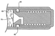
図2は、製剤75を含むリザーバ65内に挿入して使用され、且つ、薬物送達装置55のリザーバ本体60によって規定される本発明のプラグ10の切取図である。プラグ10は内側プラグ部品20および外側プラグ部品40を含む。内側プラグ部品20は外側プラグ部品内に配置される。本態様では、膨張制御チャンネル21は、内側プラグ部品20の第一の端(流入口35を規定する)から、該内側プラグ部品の本体を通って縦方向に伸びた部分;内側プラグ部品20から該内側プラグ部品20の外壁へと横方向に伸びた部分;および、本態様では内側プラグ部品20と外側プラグ部品40との接合面によって規定され、具体的に本態様では内側プラグ部品20の外壁(図2では溝として示されている)と外側プラグ部品40の内壁とによって規定される螺旋部分からなる。
【0069】
図2のプラグ10はさらに排出チャンネル41を規定し、本態様において排出チャンネル41は外側プラグ部品40の外壁とリザーバ本体60の内壁との接合面によって規定される。排出チャンネル41は外側プラグ部品40を通って通路または「ゲート」30を介して膨張制御チャンネル21と交通する。使用中にリザーバ65に隣接する内側プラグ部品20の端にある行き止まりの通路として表され、且つ、ゲート30の反対側に位置する調整孔28は、プラグの製造および組立てを容易にし、これによって、膨張制御チャンネル21と排出チャンネル41とを確実に液体接触させる。使用中、製剤75は、リザーバ65から流入口35へと流れ、膨張チャンネル21、排出チャンネル41を通って流出口45から流出する。本態様において、流出口45は、矢印70、71、72、および73が示す流路によって表されるように、外側プラグ部品40の外壁および内壁によって規定される。
【0070】
プラグ10とリザーバ本体60との間の接合面の封止は、装置内で生じる製剤の最大圧力に耐えるように設計してもよい。通常、プラグ10をリザーバ65から移動させるために必要な圧力は、リザーバ65内の圧力の少なくとも約10倍である。
【0071】
ひとつの態様では、実質的に薬物を含まない、不混和性で且つ流動性の物質が排出チャンネル41内に提供される。該物質はリザーバ65から送達される製剤と不混和性である。不混和性物質は、例えば、装置の埋植後に該不混和性物質が排出チャンネルから押し出され、且つ、流出口から流出するよう、室温または他の保管温度では固体であり、且つ、体温下では排出チャンネルから押出可能になってもよい。したがって、不混和性材料物質によって、プラグおよびリザーバへの逆拡散の防止が容易になる。
【0072】
図3に示す別の態様では、排出チャンネル41はリザーバ本体60の外壁と外側プラグ部品40の内壁との接合面によって規定される。外側プラグ部品40は、リザーバ本体60の少なくとも一部分およびリザーバ本体60内に設置される内側プラグ部品20を収容できるよう適合およびサイズ決定される(例えば、外側プラグ部品40は、キャップのようにリザーバ本体60の端にかぶせてもよい)。膨張チャンネル21は、内側プラグ部品20の少なくとも一部分によって規定される。図3に示す態様では、膨張チャンネル21は内側プラグ部品の外壁とリザーバ本体60の内壁との接合面によって規定されている。矢印70、71、および72で示すように、本態様では、製剤は流入口を通る流路を通って移動し、膨張チャンネル21、ゲート30、排出チャンネル41を通って流出口45から流出する。
【0073】
図4および図5は、流路内に配置されたフリットをプラグが含む、本発明のプラグの典型的な態様を示した図である。図4の態様では、フリット50は、外側プラグ部品40内で且つ流路の外部流出口45の出口の直前に取り付けられている。外側プラグ部品40は、(本態様では外側プラグ部品40外壁の溝によって一部が提供されている)排出チャンネル41とフリット50との間に液体接触を提供する追加的な通路47を含む。プラグ10が薬物送達装置のリザーバ内に配置されている場合、製剤は流入口35へと流れ、膨張制御チャンネル21、第一の外側プラグ部品壁の通路または「ゲート」30、排出チャンネル41、第二の外側プラグ部品壁の通路47を通ってフリット50に入り、流出口45から流出する。
【0074】
図5に示す別の態様では、プラグ10は、内側プラグ部品20、外側プラグ部品40、フリット50を含み、且つ、膨張制御チャンネル21を規定する。本態様では、フリットによって製剤の流れを調節できるため、フリットの配置によって排出チャンネルの必要性が回避される。したがって、製剤は流入口35に流れ、膨張制御チャンネル21、内側プラグ部品の通路26を通ってフリット50に流入する。
【0075】
図11〜図16に示す本発明の別の態様では、内側プラグ部品20は膨張制御チャンネル内に滑動可能な状態で配置される。内側プラグ部品20は、ゲート30を閉じるため、充填後且つ送達前に位置付けられ、これによって膨張制御チャンネル21と排出チャンネル41との間の液体接触を妨げる。内側プラグ部品20は、製剤75の熱膨張(Vlxで表される)に十分対応できるだけの膨張制御チャンネル21の容積を提供するよう、膨張制御チャンネル21内で一定距離を滑動可能である。製剤の送達が所望される場合は、流入口35をつくるために内側プラグ部品20を移動させるよう、且つ、内側プラグ部品20の近位端がゲート30を越えるだけの十分な距離にわたって内側プラグ部品20を移動させるよう、製剤が内側プラグ部品20の近位端を押す。内側プラグ部品20の滑動によってゲート30が「開い」て液体接触が確立され、これによって、リザーバ65、膨張制御チャンネル21、ゲート30、排出チャンネル41、および流出口45を通る流路が規定される。
【0076】
図11および図12に示す好ましい態様では、膨張チャンネル21の壁は外側プラグ部品40の本体によって規定される。本態様では、該壁は実質的に滑らかであり、これにより内側プラグ部品20は膨張チャンネル21の壁に沿って滑らかに滑動できる。上述の態様と同様に、内側プラグ部品20の滑動によって、膨張制御チャンネル21は製剤75の熱膨張(Vlxで表される)に十分に対応できる容積を有するようになる。製剤の送達が所望される場合は、流入口35をつくるために内側プラグ部品20を移動させるよう、且つ、内側プラグ部品20の近位端がゲート30を越えるだけの十分な距離にわたって内側プラグ部品20を移動させるよう、製剤が内側プラグ部品20の近位端を押す。内側プラグ部品20の滑動によってゲート30が「開い」て液体接触が確立され、これによって、リザーバ65、膨張制御チャンネル21、ゲート30、排出チャンネル51、および流出口45を通る流路が規定される。
【0077】
通常、排出チャンネル41は外側プラグ部品40の外壁とリザーバ本体60の内壁との接合面によって規定される。排出チャンネルは、図11および図12に示すように、外側プラグ部品30の外壁上の溝とリザーバ本体60の内壁とによって規定される。または、排出チャンネルは外側プラグ部品の外壁とリザーバ本体の内壁に沿った溝とによって規定されてもよい。図13および図14に示すように、関連する態様では、排出チャンネル41は内側プラグ部品20の外壁と膨張制御チャンネル21の内壁との接合面によって規定される。この典型的な態様では、流出口45は外側プラグ部品40の本体によって規定される。
【0078】
別の態様では、図15および図16に示すように、内側プラグ部品20および外側プラグ部品40はリザーバ本体60内に配置される別の部品として提供される。外側プラグ部品40はリザーバ本体65内に安定的に取り付けられ、内側プラグ部品は膨張制御チャンネル21内の外側プラグ部品40の近傍且つ製剤75に隣接する位置に滑動可能な状態で配置される。上述の他の態様と同様に、製剤75の熱膨張によって内側プラグ部品20が移動し、膨張制御チャンネル21は熱膨張(体積Vlx)に十分に対応できるだけの容積を有するようになる。送達開始時には、膨張制御チャンネル21を排出チャンネル41と液体接触させるために、ゲート30が開くまで製剤75が内側プラグ部品20の近位端に対して押し付けられる。本実施例では、排出チャンネル41は、内側プラグ部品20の外壁と外側プラグ部品40の外壁とリザーバ本体60の内壁との接合面によって規定される。図17および図18に示す態様では、内側プラグ部品20は、リザーバ65から膨張チャンネル21への製剤75の漏出の防止に資するよう、さらにOリング80を含む。
【0079】
組立ておよび使用
図6〜図10に、薬物送達装置で使用するため本発明のプラグを挿入する様子を示す。図に示すように、プラグ10を矢印15の方向に移動させることによって、リザーバ65に製剤75が充填され且つリザーバ65にプラグ10が挿入される。プラグ10の挿入中にトラップされた空気5は、内側プラグ部品20の流入口35、膨張制御チャンネル21、排出チャンネル41を通って移動し、リザーバ60の内壁と外側プラグ部品40の外壁との間の隙間から抜ける。プラグ10および薬物送達装置から出る空気5の流れ(図8に矢印6で示す)の後には、流入口35および膨張チャンネル21に入る製剤の流れが続く。例えば保管中の製剤の熱膨張によって、製剤液面(矢印76で示す)が上昇すると、製剤が膨張チャンネル21を通って移動する。製剤は排出チャンネル41へと移動する可能性があるが、図9および図10に示すように、流出口45への移動は、まったく生じないかまたは実質的に生じない。
【0080】
図3に示すような薬物送達装置の組立ては、2段階のプラグ組立て法で実現してもよい。例えば、内側プラグ部品20の挿入の後に室温(充填温度約22℃)で製剤が実質的に完全にリザーバおよびプラグの上まで満たすよう、リザーバ65に製剤75を充填した状態で組立てを開始する。組み立てるには、まず、好ましくはトラップされた空気が膨張制御チャンネル21を通ってシステム外に移動できるような方式で、内側プラグ部品20をリザーバ65に挿入する。次に、組み立てた内側プラグ部品20およびリザーバ本体60にかぶせるように外側プラグ部品49を配置する。
【0081】
図11〜図14に示すプラグの組立ては、薬物送達装置のリザーバの遠位端にプラグを挿入することによって、1段階の工程で行ってもよい。プラグの挿入は、リザーバに製剤を充填する前でもまたは充填した後でもよい。組立ておよびリザーバへの充填後に、膨張制御チャンネル21と排出チャンネル41とを接続するゲート30が閉じられるよう(例えば、内側プラグ部品20によって排出チャンネル41との液体接触により遮断されるよう)、内側プラグ部品20を膨張制御チャンネル21内に滑動可能な状態で配置する。リザーバ内の製剤75の熱膨張により、内側プラグ部品20の近位端が押される。内側プラグ部品20に対する製剤の力が十分である場合、内側プラグ部品20は膨張制御チャンネル21の中を滑動し、これによって、膨張する製剤に対応する。膨張制御チャンネル21は、ゲート30の開放を生じさせることなく、したがって排出チャンネル41への製剤の流れを掃除させることなく、熱膨張に十分対応できるだけの容積を有する。図11および図12に示すように、リザーバ内にトラップされた空気がある場合はこれを放出でき、且つ、膨張制御チャンネル21内に圧力を蓄積することなく内側プラグ部品20が自由に外側プラグ部品40内を滑動できるよう、膨張制御チャンネル21は外側プラグ部品40の遠位端を通って伸びていてもよい。図13および図14の態様では、内側プラグ部品20滑動中の圧力を軽減させるため、排出チャンネル45によって空気を放出してもよい。
【0082】
装置からの製剤の送達を開始する際、製剤は内側プラグ部品20の近位端に対して押し付けられる(例えば図12、図14、および図16を参照)。内側プラグ部品の近位端に対する製剤75の力によって、ゲート30が開くまで内側プラグ部品20が膨張制御チャンネル21内を滑動する。ゲート30が開くと、製剤75が排出チャンネル41へ流入し、かつ、流出口45から流出する。
【0083】
実施例
当業者に本発明の作成方法および使用方法についての完全な開示および説明を提供するために以下の実施例を記載するが、これら実施例は、本発明者らが発明と考える範囲を限定するものではない。これら実施例は、以下の実験が、行われたすべてまたは唯一の実験であることを意味するものではない。記載の数値(例えば、量、温度など)は正確性を期すよう努力が払われているが、ある程度の実験誤差および偏差は含みうるものと理解されるべきである。
【0084】
実施例1:
図2に示すような原型プラグを製造した。内側プラグ部品はチタンから機械加工した。直径約2.2987 mm、長さ5.062 mmであった。内側プラグ部品の中心に、長さ4.689 mmの膨張制御チャンネルの縦方向部分(内径0.43 mm)を作製した。直径0.254 mmの膨張制御チャンネルの横方向部分を内側プラグ部品本体の外側に作製した。膨張制御チャンネルをさらに延長するため、内側プラグ部品外壁により溝(ピッチ0.400mm、深さ0.330 mm、幅0.279)を規定した。
【0085】
外側プラグ部品もチタンから機械加工した。外側プラグ部品は外径0.1185 mmであり、且つ、内側プラグ部品を収容するためのチャンバーを規定した。収容チャンバーの深さは0.200 mm、内径は0.090 mmであった。ゲート(すなわち、外側プラグ部品の内壁から外側プラグ部品の外壁までの通路)は直径0.0145 mmの穴として作製した。リザーバ本体内で使用する際の排出チャンネルを規定するため、外側プラグ部品外壁に溝(ピッチ0.0157 mm、深さ0.0020 mm、幅0.0028 mm)を作製した。
【0086】
プラグを挿入するリザーバ本体は、直径約3.150 mm、長さ約43.18 mmであった。部品は、プレスにより組み合わせた。
【0087】
装置のリザーバを満たし、且つ、体内埋植をシミュレートするため37℃の水槽中にプラグと共に装置を配置することによって、プラグを試験した。このプラグを用いて作成されたサンプル装置は、水槽内に配置した際、製剤の異常な放出(すなわち、装置中の製剤の熱膨張による製剤の放出)を示さなかった。このことは、本発明のプラグなしで埋植する際に生じうる、薬物の望ましくない「バースト」が該プラグによって防止されたことを示唆している。対照的に、本発明のプラグを用いない装置は、埋植直後に製剤約1.5 μlを放出するという、望ましい送達パターンとは異なる放出を示した。
【図面の簡単な説明】
【0088】
【図1】対流性送達システムの略図である。
【図2】薬物送達装置のリザーバ中で使用するために挿入された本発明のプラグの切取図である。
【図3】薬物送達装置と併用するために組み立てられた本発明のプラグの切取図である。
【図4】製剤流路内且つ流出チャンネル前に配置されたフリットを含む本発明のプラグの切取図である。
【図5】排出チャンネルの流路内に配置されたフリットからなる本発明のプラグの切取図である。
【図6−10】使用のためリザーバ内にプラグを挿入している際の、本発明のプラグおよび薬物送達装置のリザーバの切取図である。
【図11−12】外側プラグ部品で規定される膨張制御チャンネル内で内側プラグ部品が滑動できるような、本発明の典型的なプラグの切取図である。
【図13−14】外側プラグ部品で規定される膨張制御チャンネル内で内側プラグ部品が滑動できるような、本発明の典型的なプラグの切取図である。
【図15−16】リザーバ本体で規定される膨張制御チャンネル内で内側プラグ部品が滑動できるような、本発明の典型的なプラグの切取図である。
【図17−18】リザーバ本体で規定される膨張制御チャンネル内で内側プラグ部品が滑動でき、且つ、該内側プラグ部品がOリングを含むような、本発明の典型的なプラグの切取図である。【Technical field】
[0001]
Field of the invention
The present invention relates to devices and methods for facilitating control of drug delivery.
[Background Art]
[0002]
Background of the Invention
Implantable drug delivery devices are an excellent therapeutic tool for treating various conditions and diseases, especially when the treatment is long-term. Implantable drug delivery devices avoid the inconvenience and pain that can be associated with multiple administrations of a drug, and further avoid, for example, bolus administration (eg, as opposed to parenteral injection administration). And improve the patient's compliance by improving the therapeutic benefit. Devices that contribute to precise control of drug delivery can deliver drugs at predictable and reliable doses and rates (eg, independent of the environment in which the device is implanted), and thus interest in such devices Is particularly high.
[0003]
A variety of implantable drug delivery devices have been developed, which implement the transfer of drug from a reservoir to a treatment site to be administered based on a variety of different mechanisms. Generally, such delivery techniques may be based on, for example, a diffusion, erosion, or convection mechanism. Drug delivery devices based on convection systems generally have advantages such as being able to refill the device and being compatible with catheters to deliver the drug locally to the treatment site. As such, they are of particular interest in the art. Typical convection systems include electromechanical pumps, osmotic pumps, electroosmotic pumps, electrochemical pumps, hydrolysis systems, piezoelectric pumps, rubber-elastic pumps, vapor pressure pumps, and electrolytic pumps. It is not limited.
[0004]
In the development of implantable devices, several challenges have arisen in the field of drug delivery, particularly with respect to drug delivery control. One such challenge is the ability to precisely control drug delivery from the time of startup (eg, immediately after implantation of a drug delivery device). For example, changes in environmental temperature during storage and after implantation can cause the formulation to swell and shrink, which can affect the delivery of the formulation after implantation. Swelling of the formulation after implantation can result in "overdose" in which small amounts of the formulation are released in an uncontrolled manner, which is particularly problematic when using highly concentrated drugs. Changes in ambient temperature can also cause the air trapped in or between the reservoir and the outlet to expand and contract, which can also adversely affect controllability at the start of drug delivery. There is. In addition, the flow of the formulation may "split" at the beginning of delivery. This means that the formulation is not in a substantially continuous flow, but has one or more discontinuous parts before the mainstream of the formulation separated by bubbles or gas bubbles (eg, "bursts"). This is the phenomenon. As a result, at startup, the formulation can be delivered without precise control.
[0005]
One way to overcome these problems is to make the channel exiting the reservoir small enough to allow flow regulation even when the formulation is in an inflated state. However, channels that are small enough to regulate flow are generally unacceptably long (and, for example, unacceptably slow delivery at start-up) or have insufficient volume to accommodate thermal expansion, Thus, it can cause the formulation to leak out of the reservoir. The reservoir can be accurately positioned during manufacture of the drug delivery device in a manner that allows for swelling of the formulation (eg, swelling due to changes in environmental temperature during storage and after implantation) without loss of contents from the reservoir. It is well known that filling is very difficult.
[0006]
As is apparent from the above, there is a need for a device that can be used with a drug delivery device, particularly a convective drug delivery device, and that avoids problems at the start of drug delivery. The present invention solves this problem.
DISCLOSURE OF THE INVENTION
[0007]
Summary of the Invention
SUMMARY OF THE INVENTION The present invention is a plug for use with a drug delivery device that defines an evacuation channel and an expansion control channel that accommodates thermal expansion of the formulation in the drug delivery device reservoir. In one embodiment, the plug includes an inner plug component and an outer plug component that define an expansion control channel that facilitates the release of trapped air and accommodates thermal expansion of the formulation from the sealed drug reservoir. Including. The plug further defines an evacuation channel and may optionally further include a frit located in the flow path immediately before the delivery port. Or both may be used.
[0008]
In one aspect, the invention provides a plug comprising an inner plug component and an outer plug component adapted to receive the inner plug component, the plug defining an inlet, an expansion control channel, and an outlet. Features. The inlet, expansion control channel, and outlet of the plug define a flow path inside and outside the plug. In one aspect, at least a portion of the inflation control channel defines a passage through the inner plug component body. In another aspect, the inner plug component can slide within the inflation control channel. In a related aspect, the expansion control channel is defined by the outer plug component such that the slidable inner plug component is received within the outer plug component. In another related aspect, the inflation control channel is defined by adjacent ends of the inner and outer plug components and the inner wall of the reservoir body of the drug delivery device.
[0009]
The invention, in another aspect, relates to a drug delivery device that includes the plug of the invention. In one embodiment, the drug delivery device is implantable.
[0010]
In yet another aspect, the present invention relates to a method of drug delivery using a drug delivery device including the plug of the present invention. In one embodiment, the drug delivery device is implantable.
[0011]
A primary object of the present invention is to control drug delivery while avoiding problems with conventional devices such as formulation leakage (eg, due to thermal expansion of the formulation during storage), bursting or bolus administration of the formulation upon start-up. It is.
[0012]
One advantage of the present invention is that the reservoir can be accurately filled while maintaining an outflow path that helps to reduce the effects of thermal expansion of the fluid in the reservoir.
[0013]
One of the key advantages of the present invention is that plugs can be used to prevent "overdose" or early uncontrolled drug release (e.g., "burst") that can result from thermal expansion due to brief changes in environmental temperature. Is helpful.
[0014]
Another advantage is that the present invention minimizes or avoids trapping of air during assembly, which can lead to problems that can be caused by trapped air, such as differences in the rate of expansion of the formulation in the reservoir and the rate of air expansion. Problems that occur due to the above problems can be minimized or avoided.
[0015]
Another advantage of the present invention is that the starting time of the drug delivery device can be precisely controlled.
[0016]
Another advantage of the present invention is that the outflow path can be extended while maintaining more efficient and volume efficient reservoir and delivery system scale.
[0017]
Yet another advantage of the present invention is that the plug allows for small reservoirs to tolerate filling and temperature changes, while at the same time visually or otherwise inspecting for proper filling before completing the closure of the reservoir. It can be confirmed by the method.
[0018]
Another advantage of the present invention is that the formulation can be retained in the delivery device until the desired time of delivery (eg, during storage, transport, etc., the plug prevents the formulation from leaking out of the reservoir).
[0019]
The above, and other objects, benefits and features of the present invention will become apparent to those skilled in the art from the following more detailed methodology and description.
[0020]
Description of the preferred embodiment
Hereinafter, the present invention will be described. However, since specific devices, materials, formulations, or typical embodiments described in the present specification can be variously changed, the present invention is not limited thereto. It should be understood that there is no. It is further understood that the terms used in the specification are for the purpose of describing particular embodiments only, and are not intended to limit the scope of the invention, which is limited solely by the appended claims. It should be.
[0021]
As used in this specification and the appended claims, the singular forms "a," "an," and "the" include plural referents unless the content clearly dictates otherwise. . Thus, for example, "a drug delivery device" includes a plurality of such devices, and "the assembly method" includes equivalent steps and methods well known to those skilled in the art.
[0022]
Unless defined otherwise, all technical and scientific terms used herein have the same meaning as commonly understood by one of ordinary skill in the art to which this invention belongs. Although any methods, devices and materials similar or equivalent to those described herein can be used in the practice of the present invention or experimentally, preferred methods, devices and materials are described below.
[0023]
All publications mentioned herein are used herein for the purpose of explaining and disclosing the statements and methodologies set forth in the publications that may be used in connection with the present invention. Incorporated by reference. The publications mentioned herein are provided solely for their disclosure prior to the filing date of the present application. Nothing in this specification should be construed as an admission that the invention is not entitled to antedate such disclosure by virtue of prior invention.
[0024]
Definition
As used herein, the term "drug" includes any substance suitable for delivery to a treatment site to be administered. Such substances include pharmaceutically active drugs and biologically compatible substances which do not themselves exhibit drug activity but which have the desired effect at the treatment site, for example by washing or perfusing the treatment site. (Eg, physiological saline).
[0025]
The term "therapeutically effective amount" means the amount of a therapeutic agent effective to produce the desired therapeutic effect, or the rate of delivery of the therapeutic agent. The exact desired therapeutic effect may depend on the condition being treated, the formulation administered, and various other factors as will be recognized by those skilled in the art.
[0026]
As used herein, "delivery site" generally refers to an area of the body where a drug is delivered for local treatment or entry into the systemic circulation. Typical delivery sites include, but are not necessarily limited to, subcutaneous, intravenous, intraarterial, intramuscular, intrafat tissue, and intralymphatic sites.
[0027]
The term "implantation site" refers to a site within a subject where a drug delivery device is introduced and placed.
[0028]
As used herein, “drug delivery device” means an implantable device that is generally suitable for delivering a selected drug and generally suitable for use with the present invention. Thus, "drug delivery device" includes any implantable device having a mechanism of action compatible with the present invention. Such devices include convective systems (eg, osmotic pumps, electromechanical pumps, electroosmotic pumps, electrochemical pumps, hydrolysis systems, piezoelectric pumps, rubber elastic pumps, vapor pressure pumps, electrolytic pumps). However, it is not necessarily limited to these.
[0029]
"Patterned" or "temporal", as used in reference to drug delivery, refers to a pattern (usually, a time period other than a time period associated with a bolus injection, etc.) (Substantially regular pattern). "Patterned" or "temporal" drug delivery refers to an increase or decrease in dosage rate or range of dosage rates (e.g., amount of drug per unit time or volume of formulation per unit time). Refers to drug delivery that is substantially constant or pulsatile, and further refers to continuous or substantially continuous or long term delivery.
[0030]
The term "controlled drug delivery device" is such that the release (e.g., dose rate, timing of release) of the drug or other desired substance contained in the drug is controlled or determined by the device itself, rather than the environment of use. Device.
[0031]
The term “subject” refers to any subject, but usually refers to the mammal (eg, human, dog, cat, horse, cow, etc.) for which delivery is desired.
[0032]
Summary of the Invention
The present invention avoids problems with, for example, swelling or deflation of a formulation that occurs in a reservoir of a drug delivery device without significant or substantially no air in a sealed drug reservoir. And a method and apparatus for delivering a drug from a drug delivery device. Another requirement of the present system is to provide an outlet from the device, especially to regulate the flow of the formulation through the channel with very little flow and very little volume. Overall, the present invention provides a passageway that is small enough to regulate the delivery of the formulation from the reservoir of the drug delivery device, but at the same time is not unacceptably long and has insufficient volume to accommodate thermal expansion. A passage needs to be provided.
[0033]
The present invention provides a plug consisting of an inner plug component and an outer plug component, as well as a first channel having sufficient volume for thermal expansion (referred to herein as an expansion control channel), and a reservoir. A second channel of smaller size that regulates the delivery of the formulation from the drug reservoir without draining the formulation from the drug reservoir nor allowing liquid surrounding the drug delivery device to penetrate into the plug and drug reservoir (discharged herein) These objectives are achieved by defining a channel.
[0034]
Hereinafter, the present invention will be described in detail.
[0035]
Expansion control channel
In all aspects, at least a portion of the plug defines an inflation control channel. The expansion control channel has a sufficient volume to accommodate thermal expansion of the drug product delivered from the reservoir of the drug delivery device, and discharges the drug from the reservoir to the outlet of the device during drug delivery. Connected to the channel.
[0036]
Given the dimensions of the inflation control channel, a convective delivery system 100 (see FIG. 1) having a
Vt= Vd + Vo (1)
The
1 / Vt(ΔV / ΔT) = a (2)
Assuming that a is constant over the temperature range, the volume expansion chamber VlxCan be calculated by the following equation:
Vlx= aVt(TB -TS) (3)
Thus, the volume expansion chamber is, for example, the value a (the volume expansion coefficient of the delivered formulation), Vl(The volume of the opening, depending on the length of the passage through the opening), (TB -TS) (Body temperature (implantation temperature) TBAnd storage temperature TSDifference), the diameter of the opening, the length of the opening (B-A), etc., may be designed in accordance with the present invention.
[0037]
For example, for organic drugs ao = 1.1 x 10⁻³/ ° C, a for aqueous formulationsa = 3 x 10-Four/ ° C. According to equation (3), the volume of the drug reservoir V = 0.200 cmThreeAnd ΔT (or (TB -TS)) = V at 17 ° C for organic and aqueous preparationslxBecomes:
Vlx = a (0.2) (17) = a (3.4)
Vlx = a0(3.4) = (1.1 x 10⁻³) (3.4) = 3.7 μl (organic liquid formulation), and
Vlx = aa(3.4) = (3.1 x 10-Four) (3.4) = 1.0 μl (aqueous formulation)
Further, the system may be designed taking into account the coefficient of linear expansion of the material through which the formulation flows. The values for the thermal expansion of the formulation and the components of such formulation are readily available and / or can be readily determined by methods known in the art.
[0038]
The plug of the present invention may provide an inflation control channel in a variety of ways. For example, the inflation control channel extends from one end of the inner plug component (the first end that contacts the formulation in the drug reservoir during use) and through substantially the entire length or a portion of the inner plug component to the outlet channel of the plug. May have been reached. In one exemplary embodiment, the inflation control channel includes a longitudinal channel, a lateral passage, and a helical portion through the inner plug component. A longitudinal channel defining an inlet at a first end of the inner plug part (e.g., the end that contacts the formulation in the reservoir during use) passes through the body of the inner plug part and a second channel of the inner plug part. It extends in the direction of the edge until the desired distance is reached. This longitudinal portion may be located at the center of the inner plug component, or may be located off-center, as desired. The lateral portion of the inflation control channel extends from the longitudinal portion of the inflation control channel to a spiral portion, thereby providing a flow path from the longitudinal portion to the outer wall. The helical portion of the expansion control channel allows liquid contact from the lateral portion to an outlet channel (described below) defined by at least a portion of the outer plug component, or to an outlet (described below) when used with a frit. Become. The helical portion of the expansion control channel is defined by at least a portion of the inner plug component body. In one aspect, the spiral portion of the inflation control channel is defined by the interface between the outer wall of the inner plug component and the inner wall of the outer plug component (eg, a groove in the outer wall of the inner plug component and the inner wall of the outer plug component). Each of these portions of the inflation control channel may vary in size, as will be readily appreciated by those skilled in the art reading this disclosure.
[0039]
In another aspect, the inflation control channel is defined by an outer plug component and an end of the inner plug component adjacent to the reservoir during use. In this aspect, the inner plug component is slidably received in the outer plug component body. As the product expands toward the proximal end of the inner plug component, the inner plug component slides within the outer plug component, thereby providing an inflation control channel within the proximal end of the plug. The inner plug is held by an outer plug piece that is stably attached to the drug delivery device so as not to escape from the distal end of the device.
[0040]
In another aspect, the inner plug component is slidable along a wall of the reservoir body of the drug delivery device and the outer plug component is stably mounted within the distal end of the drug delivery device. As the formulation expands toward the inner plug part, the inner plug part slides within the reservoir body (outer plug part), thereby providing an inflation control channel within the proximal end of the plug. The outer plug component, which is again stably mounted within the drug delivery device, prevents the inner plug component from protruding from the distal end of the drug delivery device.
[0041]
The volume of the expansion control channel may be increased by changing the shape of the channel. For example, the expansion control channel may be extended by meandering all or part of the channel within or along the side of the inner plug component.
[0042]
Inner plug parts
The inner plug part of the plug according to the invention is housed in the outer plug part and at least partly seats in the outer plug part. The inner plug part, alone or in combination with the outer plug part, defines an inflation control channel (the channel through which the formulation first flows when used with a drug delivery device). The inflation control channel is sized (diameter and length) to control the trapping of air during assembly (e.g., insertion of a drug delivery device plug to seal the drug reservoir). Further, the inflation control channel is sized to accommodate thermal expansion of air and / or the formulation so as to prevent or substantially reduce drug release from the reservoir prior to actuation.
[0043]
The size of the inner part is a groove along the outer wall of the inner plug part or the inner wall of the outer plug part such that the inflation control channel in the fully expanded state is defined by the interface between the inner part outer wall and the inner wall of the outer plug part. May be minimized by defining the inflation control channel as In one aspect, a first portion of the inflation control channel extends longitudinally through the inner plug component body, extends laterally through the inner plug component body, and downwards by the outer wall of the inner plug component body. And a spiral groove that draws a spiral. This is done so that the helical groove defines a fully inflated control channel when the inner component is positioned within the outer plug component. Suitable materials include hard plastics, metals, alloys, ceramics, polymers, and the like, such as materials that can well define the dimensions of the discharge channel. A material with a low surface energy is desirable to prevent leakage of liquid through the channel. Materials such as metals may coat the surface to reduce surface energy.
[0044]
Outer plug parts
Usually, the outer plug part is the part of the plug that defines the distal end of the plug and further defines the outflow end of the drug delivery device in use. For example, the outer plug component may be operatively connected to the distal end of the drug delivery device (eg, to a delivery site or to the drug delivery device (eg, by press-fitting, screwing, snap-fitting, or by an adhesive element, and / or welding). At least a portion of the end through which the formulation is delivered to the attached catheter (by gluing, casting, etc.).
[0045]
The outer plug part is adapted to receive the inner plug part. The inner plug component may be stably mounted within the outer plug component, or may be slidable. In another aspect, the inner plug component is slidable within the reservoir body and retained by the outer plug component so as not to be pushed out of the drug delivery device. That is, the inner plug component slides within the reservoir until it only contacts the distal end of the outer plug component.
[0046]
In one embodiment, the outer plug component, alone or in combination with the drug delivery device inner wall, defines an outlet channel through which the formulation exiting the device during use passes. The drainage channel is sized to regulate the flow of drug from the reservoir and the channel of the inner plug part during drug delivery, and the leakage of the formulation from the reservoir and device, and the formulation or environment into the plug and into the reservoir Prevent backflow of liquid. Reflux can have undesirable effects, such as contamination inside the delivery device, and can also cause dilution, destabilization, or other undesirable effects on the formulation in the reservoir.
[0047]
The parameters relating to the size of the outflow channel that control the flow of the formulation through the outflow channel and regulate the back diffusion are described, for example, in US Pat. Nos. 5,985,305 and 5,728,396. Briefly, to reduce or mitigate back-diffusion, flow should be such that the average linear velocity of the formulation released in the environment of use is higher than the average inward flux of the material in the environment of use due to diffusion or penetration. The length, cross-sectional shape, and area of the
[0048]
The convection of the active
Qca = (Q) (Ca) (Four)
In the above equation, QcaIs the convective movement of drug A (mg / day), Q is the overall convective movement of drug and drug diluent (cmThree/ Day), CaIs reservoir QcaDrug concentration in the formulation within 65 (mg / cmThree). The diffusive flow of the drug passing through the material of the
Qda = DπrTwoΔCa/ L (5)
In the above equation, QdaIs the diffusion transfer of drug A (mg / day), and D is the diffusion rate (cmTwo/ Day), r is the effective radius inside the channel (cm), ΔCaIs the difference between the concentration of Drug A in the reservoir and the concentration of Drug A outside the
[0049]
Usually, the drug concentration in the reservoir is much higher than the drug concentration outside the outlet in the body, in which case the difference ΔCaIs the chemical concentration C in the reservoiraMay be approximated by:
Qda = DπrTwoCa/ L (6)
Typically, the diffusion flux of the drug is maintained at less than 10% of the convection of the drug. This is expressed as:
Qda/ Qca = DπrTwoCa/ QCaL = DπrTwo/ QL ≤ 0.1 (7)
[0050]
For a delivery system with a purge rate of 1.5 μl / day, a reservoir volume of 150 μl, delivering the formulation over 100 days, and having a 1.1 cm long, 10 mm diameter opening, the diffusion coefficient D = 2 × 10⁻⁶ cmTwo/ Sec, ratio (Qda / Qca) = 5.2 x 10⁻³Solve equation (7) as For this opening size, the volume is Vl = 5 μl and V estimated in FIG.lx <VlMeet the criteria of Typical VlxRange is Vl0.1 to 0.9 times.
[0051]
Typically, the discharge channel extends through the sidewall of the outer plug component and is in liquid contact with the expansion control channel. The discharge channel may extend over substantially the entire length or a portion of the outer plug component prior to providing an outlet channel for discharging the formulation from the plug and device. By varying the shape of the discharge channel, a desired length of the discharge channel may be provided without simultaneously increasing the dimensions of the outer plug component.
[0052]
For example, the discharge channel may be a helix extending along substantially the entire length or a portion of the outer plug component body. In one aspect, the outlet channel is provided as a groove along the outer wall of the outer plug component, and after assembly of the plug used in the device, the inner wall of the drug delivery device (eg, the inner wall of the drug reservoir) and the outer plug component. The entire discharge channel is provided by its interface with the outer wall. In this aspect, the diameter of the outer plug component may be minimized for use in smaller implantable or microdevices. In another aspect, an outlet channel is provided by a combination of a channel through the outer plug piece that contacts the inflation channel and a groove in the inner wall of the drug delivery device. In another embodiment using an outer plug part adapted to accommodate a slidable inner plug part, the discharge channel may be defined by the interface between the outer plug part and the inner plug part, for example, the discharge channel may be It may be defined by the outer wall of the inner plug part and the inner wall of the outer plug part.
[0053]
Suitable materials for the outer plug part are the same as those suitable for the inner plug part. The materials used for the inner and outer plug parts can be the same or different. If the outer plug component is adapted to slidably receive the inner plug component, the inner wall of the outer plug component may be coated or otherwise treated to facilitate sliding of the inner plug component.
[0054]
Other components or elements of the plug
The plugs of the present invention may include other components that help to further enhance drug delivery control through the plug. For example, in one aspect, the plug includes a frit positioned within the flow path to provide porosity. Usually, the frit is located in the outer part and just before the outlet channel of the plug. Typically, the frit is a porous material that is placed in a passage that is to be the passage of the formulation and that provides a sufficient porosity to trap liquids and allow air to escape. In use, the frit "captures" the start of the formulation flow at startup ("burst") and traps the formulation until the mainstream of the formulation has joined the initial formulation burst. If the plug includes a frit, the outer plug component may optionally define a discharge channel as described above. For example, if a frit is placed in the flow path, the outlet may not necessarily be able to provide the desired level of controlled delivery.
[0055]
It will be readily understood that materials suitable for use in the frit will depend on various factors. Such factors include, but are not necessarily limited to, formulations that pass through the frit (eg, pH, hydrophobicity, hydrophilicity, wettability, etc. of the formulation). Typically, the material of the frit is selected to be able to wet and wick the formulation, and to be compatible and chemically resistant to the formulation. Suitable frit materials include, but are not necessarily limited to, metals, glasses, polymers, and cellulose.
[0056]
Similarly, the dimensions of the frit and the porosity provided by the frit will vary depending on various factors readily understood by those skilled in the art. Typically, the frit material is made of a material with a high surface energy to facilitate wetting. Typically, the material of the frit is a porous element, with a porosity between 30% and 90%, preferably between 50% and 90%, with a vent structure. The volume inside the porous element is VlxIs within the range of 0.1 times to 0.5 times. Usually, the volume provided by the frit is the thermal expansion volume (Vlx) May be selected and designed to accommodate the volume of liquid that may deviate from the main flow of liquid exiting the pump. For example, it may be designed so as to be able to handle a small amount of fluid (for example, 1 μl to 2 μl) that separates from the front of the fluid and flows toward the outlet of the plug.
[0057]
Drug delivery device for use with the present invention
A variety of optional drug delivery devices are suitable for use with the present invention. Typically, drug delivery devices suitable for use with the plugs of the present invention include a drug reservoir designed to contain a flowable drug, and further allow the plug to seal the drug reservoir with the plug. A device that includes a portion (eg, the plug may be positioned within a drug delivery device to provide a flow path from the drug reservoir and device).
[0058]
Typically, drug delivery devices have the ability to deliver the amount and concentration of the drug required for treatment and the ability to adequately protect the formulation from physical effects during implantation and delivery. The contents flow out uncontrolled under the pressure generated during use (e.g., acting on the drug release device as a result of the movement of the recipient or the physical forces associated with the pressure generated within the reservoir with respect to drug delivery) To prevent the drug from escaping due to physical forces), the exterior material preferably has properties that reduce the risk of leakage, cracking, breakage, or deformation. Drug reservoirs, or other means for holding or containing a drug, also use such materials and preferably are biocompatible so as to avoid unintended reactions with the active agent ( For example, if the device is to be implanted, it must be substantially non-responsive to the body or fluids to which it is administered.
[0059]
Suitable materials for the reservoir body or drug holding means of the drug delivery device of the present invention are known in the art. For example, the reservoir material may include a non-reactive polymer or a biocompatible metal or alloy. Suitable polymers include acrylonitrile polymers such as acrylonitrile butadiene styrene polymers, polytetrafluoroethylene, polyurethane, polychlorotrifluoroethylene, halogenated polymers such as tetrafluoroethylene hexafluoropropylene copolymer, Examples include, but are not necessarily limited to, polyethylene vinyl acetate (EVA), polyimide, polysulfone, polycarbonate, polyethylene, polypropylene, polyvinyl chloride / acrylic copolymer, polycarbonate / acrylonitrile / butadiene / styrene, polystyrene, and cellulose polymer. Other typical polymers are described in "The Handbook of Common Polymers" (Scott and Roff, CRC Press, Cleveland Rubber Co., Cleveland, Ohio). Metal materials suitable for use in the reservoir body include stainless steel, titanium, platinum, tantalum, gold and their alloys, gold-plated alloy iron, platinum-plated titanium, platinum-plated stainless steel, platinum-plated tantalum, platinum-plated gold and These and other alloys include iron, cobalt chrome alloys, and titanium nitride coated stainless steel, titanium nitride coated titanium, titanium nitride coated platinum, titanium nitride coated tantalum, titanium nitride coated gold, and alloys thereof. Laminates of the above materials may also be used in the reservoir body.
[0060]
When storing drugs in reservoirs containing metals or alloys, applications where size is particularly important, applications where the load capacity is large and the usage time is long, and where the formulation is sensitive to biochemical reactions at the implantation site or In applications where the body is sensitive to the formulation, titanium or titanium alloys containing more than 60% (often more than 85%) of titanium are particularly preferred. Most preferably, the drug delivery device is designed to store the drug above room temperature.
[0061]
Drug delivery devices suitable for use with the present invention may be based on any of a variety of operating modes. Typically, the plug of the present invention may be used with a drug delivery device that includes a reservoir for containing a flowable drug that delivers the drug to a treatment site to be administered. The plugs of the present invention have particular application for use in convective devices that include a drug reservoir. Typical devices include, but are not necessarily limited to, electromechanical pumps, osmotic pumps, electroosmotic pumps, electrochemical pumps, hydrolysis systems, piezoelectric pumps, vapor pressure pumps, and electrolytic pumps. Drug release devices based on mechanical or electromechanical infusion pumps may also be suitable for use with the present invention. Examples of mechanical or electromechanical infusion pumps include, for example, those described in U.S. Pat.Nos. 4,692,147, 4,360,019, 4,487,603, 4,360,019, 4,725,852, and the like. However, the present invention is not necessarily limited to these. Examples of osmotic devices suitable for use in the present invention include U.S. Patent Nos. 3,760,984, 3,845,770, 3,916,899, 3,923,426, 3,987,790, 3,995,631, 3,916,899, 4,016,880, No. 4,036,228, No. 4,111,202, No. 4,111,203, No. 4,203,440, No. 4,203,442, No. 4,210,139, No. 4,327,725, No. 4,627,850, No. 4,865,845, No. 5,057,318, No. 5,059,423, No. 5,112,614. No. 5,234,692, No. 5,234,693, No. 5,728,396, No. 5,985,305, and PCT Publication No. WO 97/27840, but are not necessarily limited thereto.
[0062]
Depending on the drug delivery device, the plugs of the present invention can be particularly small (eg, 0.01 μg / hr to 200 μg / hr) and / or small volume (eg, 0.01 μl / day to 100 μl / day (ie, about 0.0004 μl). / Hour to about 4 μl / hour), preferably about 0.04 μl / day to about 10 μl / day, usually about 0.2 μl / day to about 5 μl / day, typically about 0.5 μl / day to about 1 μl / day). It is particularly useful in controlling drug delivery. In one embodiment, the volume / time delivery rate is substantially constant (e.g., delivery is typically at a rate of about ± 5% to 10% of the volume over the time period).
[0063]
In some embodiments, it may be desirable to provide a drug delivery catheter with the drug delivery device. For example, when the implantation site and the desired delivery site are not the same or are not in close proximity. Typically, drug delivery catheters have a first end (or “proximal” end) that connects to a drug delivery device and a second end (or “distal” end) for delivering a drug-containing formulation to a desired delivery site. ) Having a substantially hollow long part. When using a drug delivery catheter, the lumen of the drug delivery catheter is connected to the drug reservoir of the drug delivery device via the channel defined by the plug of the present invention, which allows the formulation contained in the drug reservoir to be transferred to the drug reservoir. A first end of the drug delivery catheter is connected to or attached to the drug delivery device for movement into the delivery catheter and out of the delivery port of the catheter located at the desired delivery site.
[0064]
The catheter body defines a lumen. The lumen has a diameter suitable for delivering the drug while preventing leakage of the drug from the drug delivery device. If the drug delivery device administers the drug by convection (eg, as in the case of osmotic drug delivery devices), the size of the lumen of the catheter extending from the reservoir of the drug release system is given by equation (7). May be designed by the method described in Theeuwes (1975), J. Pharm. Sci., 64: 1987-91. The catheter body may be of any size and shape (eg, curved, substantially straight, tapered, etc.), which may be selected based on the suitability of the drug delivery for the intended site. The distal end of the drug delivery catheter may provide a distinct opening or series of openings for drug delivery.
[0065]
Delivery formulation
Any formulation containing any drug (active substance) may be delivered using a drug delivery device comprising a plug of the invention. Drug types suitable for delivery using a drug delivery device comprising a plug of the invention include pharmacologically active peptides, polypeptides, nucleic acids encoding a gene product of interest, and such gene products (eg, , DNA, RNA, and nucleic acid-based compounds).
[0066]
Compounds of interest include chemotherapeutic agents for neoplastic tissue, anti-inflammatory agents (eg, for ischemic or inflammatory tissues), hormones or hormone antagonists (eg, for endocrine tissues), ion channel modulators (eg, cardiac And vasculature or other tissues) and neuroactive agents (eg, agents for the central nervous system, including but not limited to analgesics, including but not limited to opioids, opioid derivatives, etc.). Exemplary pharmaceuticals suitable for the present invention are described in the following sections of "The Pharmacological Basis of Therapeutics", Goodman and Gilman, McGraw-Hill, New York, NY (1993), all of which are incorporated by reference. Incorporated herein: Drugs Acting at the Synaptic and Neuroeffector Junctional Sites; Drugs Acting on the Central Nervous System; Autakoids: Autacoids: Drug Therapy of Inflammation; Water, Salts and Ions; Drugs affecting Renal Function and Electrolyte Metabolism (Drugs Affecting Renal Function and Electrolyte Metabolism); Cardiovascular Drugs ( Cardiovascular Drugs); Drugs affecting gastrointestinal tract function (Drugs Affecting Gastrointestinal Function); Drugs affecting uterine motility (Drugs Affecting Uterine Mo) tility); Chemotherapy of Parasitic Infections; Chemotherapy of Microbial Diseases; Chemotherapy of Neoplastic Diseases; Drugs used for immunosuppression (Drugs) Used for Immunosuppression); Drugs Acting on Blood-Forming organs; Hormones and Hormone Antagonists; Vitamins, Dermatology; and Toxicology.
[0067]
Typical aspects
In the following, exemplary embodiments of the plug of the invention and the use of the plug in connection with a drug delivery reservoir are provided with reference to the drawings.
[0068]
FIG. 2 is a cutaway view of the
[0069]
The
[0070]
The seal at the interface between the
[0071]
In one embodiment, a substantially drug-free, immiscible and flowable substance is provided in the
[0072]
In another embodiment shown in FIG. 3, the
[0073]
4 and 5 show typical embodiments of the plug of the present invention, wherein the plug includes a frit arranged in the flow path. In the embodiment of FIG. 4, the
[0074]
In another embodiment, shown in FIG. 5, the
[0075]
In another embodiment of the present invention, shown in FIGS. 11-16, the
[0076]
In the preferred embodiment shown in FIGS. 11 and 12, the wall of the
[0077]
Typically, the
[0078]
In another embodiment, the
[0079]
Assembly and use
6 to 10 show the insertion of the plug of the present invention for use in a drug delivery device. As shown in the figure, by moving the
[0080]
Assembly of the drug delivery device as shown in FIG. 3 may be realized by a two-stage plug assembly method. For example, assembly begins with
[0081]
Assembly of the plug shown in FIGS. 11-14 may be performed in a one-step process by inserting the plug into the distal end of the reservoir of the drug delivery device. Insertion of the plug may be before or after filling the reservoir with the formulation. After assembly and filling of the reservoir, the inner plug may be closed such that the
[0082]
Upon initiating delivery of the formulation from the device, the formulation is pressed against the proximal end of inner plug component 20 (see, for example, FIGS. 12, 14, and 16). The force of the
[0083]
Example
The following examples are set forth to provide those of ordinary skill in the art with a complete disclosure and explanation of how to make and use the invention, but these examples limit the scope of what we consider to be the invention. is not. These examples do not imply that the following experiments are all or the only experiments performed. Efforts have been made to ensure accuracy with numerical values (eg, amounts, temperatures, etc.) but it should be understood that some experimental errors and deviations may be included.
[0084]
Example 1:
A prototype plug as shown in FIG. 2 was manufactured. The inner plug part was machined from titanium. It was about 2.2987 mm in diameter and 5.062 mm in length. In the center of the inner plug part, a longitudinal section (0.43 mm inner diameter) of a 4.689 mm long expansion control channel was made. The lateral portion of the 0.254 mm diameter inflation control channel was made outside the inner plug component body. To further extend the expansion control channel, a groove (pitch 0.400 mm, depth 0.330 mm, width 0.279) was defined by the outer wall of the inner plug component.
[0085]
The outer plug parts were also machined from titanium. The outer plug part had an outer diameter of 0.1185 mm and defined a chamber for receiving the inner plug part. The depth of the containing chamber was 0.200 mm and the inside diameter was 0.090 mm. The gate (ie, the passage from the inner wall of the outer plug part to the outer wall of the outer plug part) was made as a hole having a diameter of 0.0145 mm. Grooves (pitch: 0.0157 mm, depth: 0.0020 mm, width: 0.0028 mm) were made in the outer wall of the outer plug part to define the discharge channel when used in the reservoir body.
[0086]
The reservoir body into which the plug was inserted had a diameter of about 3.150 mm and a length of about 43.18 mm. Parts were assembled by pressing.
[0087]
The plug was tested by filling the reservoir of the device and placing the device with the plug in a 37 ° C. water bath to simulate an implant. The sample device made with this plug did not show abnormal release of the formulation when placed in the aquarium (ie, release of the formulation due to thermal expansion of the formulation in the device). This suggests that undesired "bursts" of drug that could occur when implanting without the plug of the present invention were prevented by the plug. In contrast, the device without the plug of the present invention showed a release different from the desired delivery pattern, releasing about 1.5 μl of the formulation immediately after implantation.
[Brief description of the drawings]
[0088]
FIG. 1 is a schematic diagram of a convective delivery system.
FIG. 2 is a cutaway view of a plug of the present invention inserted for use in a reservoir of a drug delivery device.
FIG. 3 is a cutaway view of a plug of the present invention assembled for use with a drug delivery device.
FIG. 4 is a cutaway view of a plug of the present invention including a frit positioned within the formulation flow path and before the outflow channel.
FIG. 5 is a cutaway view of the plug of the present invention comprising a frit disposed within the flow channel of the discharge channel.
FIG. 6-10 is a cutaway view of the reservoir of the plug and drug delivery device of the present invention during insertion of the plug into the reservoir for use.
FIGS. 11-12 are cutaway views of an exemplary plug of the present invention such that the inner plug component can slide within an inflation control channel defined by the outer plug component.
FIGS. 13-14 are cutaway views of an exemplary plug of the present invention such that an inner plug component can slide within an inflation control channel defined by an outer plug component.
FIGS. 15-16 are cutaway views of an exemplary plug of the present invention such that an inner plug component can slide within an inflation control channel defined by a reservoir body.
17-18 are cutaway views of a typical plug of the present invention, such that the inner plug component can slide within an inflation control channel defined by the reservoir body and the inner plug component includes an O-ring. .
Claims (35)
内側プラグ部品;および
外側プラグ部品。The plug of claim 1, comprising:
Inner plug part; and outer plug part.
薬物送達装置の少なくとも一部を投与対象内に埋植する段階であって、該薬物送達装置が請求項1記載のプラグを含み、且つ、薬物含有製剤を保持するためのリザーバがリザーバ本体によって規定され且つ該リザーバから該プラグの流出口のへの流路を提供するため該プラグが該リザーバ内に取り付けられるような段階;および
該リザーバから投与対象の送達部位に製剤を送達する段階。A method for delivering a drug to a delivery site, comprising the following steps:
Implanting at least a portion of a drug delivery device into an administration subject, wherein the drug delivery device includes the plug of claim 1 and a reservoir for holding the drug-containing formulation is defined by a reservoir body. The plug is mounted within the reservoir to provide a flow path from the reservoir to the outlet of the plug; and delivering the formulation from the reservoir to a delivery site for administration.
Applications Claiming Priority (2)
| Application Number | Priority Date | Filing Date | Title |
|---|---|---|---|
| US25032800P | 2000-11-29 | 2000-11-29 | |
| PCT/US2001/043143 WO2002043800A2 (en) | 2000-11-29 | 2001-11-21 | Devices and methods for controlled delivery from a drug delivery device |
Publications (3)
| Publication Number | Publication Date |
|---|---|
| JP2004533275A true JP2004533275A (en) | 2004-11-04 |
| JP2004533275A5 JP2004533275A5 (en) | 2005-12-22 |
| JP4248236B2 JP4248236B2 (en) | 2009-04-02 |
Family
ID=22947285
Family Applications (1)
| Application Number | Title | Priority Date | Filing Date |
|---|---|---|---|
| JP2002545769A Expired - Fee Related JP4248236B2 (en) | 2000-11-29 | 2001-11-21 | Device and method for controlling delivery from a drug delivery device |
Country Status (6)
| Country | Link |
|---|---|
| US (1) | US20050070883A1 (en) |
| EP (1) | EP1339449A2 (en) |
| JP (1) | JP4248236B2 (en) |
| AU (1) | AU2002219793A1 (en) |
| CA (1) | CA2429945A1 (en) |
| WO (1) | WO2002043800A2 (en) |
Cited By (4)
| Publication number | Priority date | Publication date | Assignee | Title |
|---|---|---|---|---|
| JP2014507221A (en) * | 2011-02-02 | 2014-03-27 | ザ チャールズ スターク ドレイパー ラボラトリー インク | Drug delivery device |
| JP2021517832A (en) * | 2018-03-13 | 2021-07-29 | バーテックス ファーマシューティカルズ インコーポレイテッドVertex Pharmaceuticals Incorporated | Implantable devices, systems, and methods |
| CN115089851A (en) * | 2022-06-21 | 2022-09-23 | 上海力声特医学科技有限公司 | A sustainable drug delivery cochlear implant |
| WO2025204280A1 (en) * | 2024-03-27 | 2025-10-02 | テルモ株式会社 | Administration device and method for manufacturing administration device |
Families Citing this family (33)
| Publication number | Priority date | Publication date | Assignee | Title |
|---|---|---|---|---|
| US6440457B1 (en) * | 1993-05-27 | 2002-08-27 | Alza Corporation | Method of administering antidepressant dosage form |
| US7731947B2 (en) | 2003-11-17 | 2010-06-08 | Intarcia Therapeutics, Inc. | Composition and dosage form comprising an interferon particle formulation and suspending vehicle |
| TW200507893A (en) | 2003-03-31 | 2005-03-01 | Alza Corp | Osmotic pump with means for dissipating internal pressure |
| NZ542867A (en) | 2003-03-31 | 2009-02-28 | Durect Corp | Non-aqueous single phase vehicles and formulations utilizing such vehicles involving a polymer |
| EP1694310A2 (en) * | 2003-11-06 | 2006-08-30 | Alza Corporation | Modular imbibition rate reducer for use with implantable osmotic pump |
| US11246913B2 (en) | 2005-02-03 | 2022-02-15 | Intarcia Therapeutics, Inc. | Suspension formulation comprising an insulinotropic peptide |
| WO2006083761A2 (en) | 2005-02-03 | 2006-08-10 | Alza Corporation | Solvent/polymer solutions as suspension vehicles |
| US8114055B2 (en) * | 2005-05-10 | 2012-02-14 | Palyon Medical (Bvi) Limited | Implantable pump with infinitely variable resistor |
| US7637892B2 (en) * | 2005-05-10 | 2009-12-29 | Palyon Medical (Bvi) Limited | Variable flow infusion pump system |
| US8915893B2 (en) | 2005-05-10 | 2014-12-23 | Palyon Medical (Bvi) Limited | Variable flow infusion pump system |
| US8211060B2 (en) | 2005-05-10 | 2012-07-03 | Palyon Medical (Bvi) Limited | Reduced size implantable pump |
| US20070027105A1 (en) | 2005-07-26 | 2007-02-01 | Alza Corporation | Peroxide removal from drug delivery vehicle |
| JP5143131B2 (en) | 2006-05-30 | 2013-02-13 | インターシア セラピューティクス,インコーポレイティド | Two-piece internal channel flow modulator for osmotic delivery system |
| AU2007284759B2 (en) | 2006-08-09 | 2010-10-28 | Intarcia Therapeutics, Inc. | Osmotic delivery systems and piston assemblies |
| US7538652B2 (en) * | 2006-08-29 | 2009-05-26 | International Business Machines Corporation | Electrical component tuned by conductive layer deletion |
| CN101715340A (en) | 2007-04-23 | 2010-05-26 | 精达制药公司 | Suspension formulation of insulinotropic peptide and application thereof |
| US8343140B2 (en) | 2008-02-13 | 2013-01-01 | Intarcia Therapeutics, Inc. | Devices, formulations, and methods for delivery of multiple beneficial agents |
| EP2429611B1 (en) * | 2009-04-07 | 2017-03-08 | Medimetrics Personalized Drug Delivery B.V. | Valveless drug delivery device |
| US9011899B2 (en) | 2009-08-28 | 2015-04-21 | Sernova Corporation | Methods and devices for cellular transplantation |
| KR102093612B1 (en) | 2009-09-28 | 2020-03-26 | 인타르시아 세라퓨틱스 인코포레이티드 | Rapid establishment and/or termination of substantial steady-state drug delivery |
| US8366667B2 (en) * | 2010-02-11 | 2013-02-05 | Baxter International Inc. | Flow pulsatility dampening devices |
| US20120208755A1 (en) | 2011-02-16 | 2012-08-16 | Intarcia Therapeutics, Inc. | Compositions, Devices and Methods of Use Thereof for the Treatment of Cancers |
| US8568360B2 (en) | 2011-12-28 | 2013-10-29 | Palyon Medical (Bvi) Limited | Programmable implantable pump design |
| US9889085B1 (en) | 2014-09-30 | 2018-02-13 | Intarcia Therapeutics, Inc. | Therapeutic methods for the treatment of diabetes and related conditions for patients with high baseline HbA1c |
| AU2016270984B2 (en) | 2015-06-03 | 2021-02-25 | Intarcia Therapeutics, Inc. | Implant placement and removal systems |
| RU2760007C2 (en) | 2016-05-16 | 2021-11-22 | Интарсия Терапьютикс, Инк. | Polypeptides selective to glucagon receptors and their application methods |
| USD840030S1 (en) | 2016-06-02 | 2019-02-05 | Intarcia Therapeutics, Inc. | Implant placement guide |
| USD860451S1 (en) | 2016-06-02 | 2019-09-17 | Intarcia Therapeutics, Inc. | Implant removal tool |
| CA3049034A1 (en) | 2017-01-03 | 2018-07-12 | Intarcia Therapeutics, Inc. | Methods comprising continuous administration of a glp-1 receptor agonist and co-adminstration of a drug |
| CN109110899B (en) * | 2017-06-23 | 2023-10-17 | 福建金源泉科技发展有限公司 | Vitamin C slow-release structure of filtering device of bath faucet |
| USD933219S1 (en) | 2018-07-13 | 2021-10-12 | Intarcia Therapeutics, Inc. | Implant removal tool and assembly |
| WO2021146215A1 (en) | 2020-01-13 | 2021-07-22 | Durect Corporation | Sustained release drug delivery systems with reduced impurities and related methods |
| JP2024503402A (en) | 2021-01-12 | 2024-01-25 | デュレクト コーポレーション | Sustained release drug delivery systems and related methods |
Family Cites Families (39)
| Publication number | Priority date | Publication date | Assignee | Title |
|---|---|---|---|---|
| US3995631A (en) * | 1971-01-13 | 1976-12-07 | Alza Corporation | Osmotic dispenser with means for dispensing active agent responsive to osmotic gradient |
| US3760984A (en) * | 1971-09-29 | 1973-09-25 | Alza Corp | Osmotically powered agent dispensing device with filling means |
| US3845770A (en) | 1972-06-05 | 1974-11-05 | Alza Corp | Osmatic dispensing device for releasing beneficial agent |
| US3916899A (en) * | 1973-04-25 | 1975-11-04 | Alza Corp | Osmotic dispensing device with maximum and minimum sizes for the passageway |
| US3923426A (en) * | 1974-08-15 | 1975-12-02 | Alza Corp | Electroosmotic pump and fluid dispenser including same |
| US4036228A (en) * | 1975-09-11 | 1977-07-19 | Alza Corporation | Osmotic dispenser with gas generating means |
| US3987790A (en) * | 1975-10-01 | 1976-10-26 | Alza Corporation | Osmotically driven fluid dispenser |
| US4016880A (en) * | 1976-03-04 | 1977-04-12 | Alza Corporation | Osmotically driven active agent dispenser |
| US4111202A (en) * | 1976-11-22 | 1978-09-05 | Alza Corporation | Osmotic system for the controlled and delivery of agent over time |
| US4111203A (en) * | 1976-11-22 | 1978-09-05 | Alza Corporation | Osmotic system with means for improving delivery kinetics of system |
| US4203442A (en) * | 1977-08-29 | 1980-05-20 | Alza Corporation | Device for delivering drug to a fluid environment |
| US4203440A (en) * | 1978-10-23 | 1980-05-20 | Alza Corporation | Device having variable volume chamber for dispensing useful agent |
| US4210139A (en) * | 1979-01-17 | 1980-07-01 | Alza Corporation | Osmotic device with compartment for governing concentration of agent dispensed from device |
| US4360019A (en) | 1979-02-28 | 1982-11-23 | Andros Incorporated | Implantable infusion device |
| US4692147A (en) | 1980-04-02 | 1987-09-08 | Medtronic, Inc. | Drug administration device |
| US4327725A (en) * | 1980-11-25 | 1982-05-04 | Alza Corporation | Osmotic device with hydrogel driving member |
| US4410328A (en) * | 1981-07-10 | 1983-10-18 | Alza Corporation | Dispensing device with internal drive |
| US4487603A (en) | 1982-11-26 | 1984-12-11 | Cordis Corporation | Implantable microinfusion pump system |
| US4627850A (en) * | 1983-11-02 | 1986-12-09 | Alza Corporation | Osmotic capsule |
| US4725852A (en) * | 1985-05-09 | 1988-02-16 | Burlington Industries, Inc. | Random artificially perturbed liquid apparatus and method |
| US4865845A (en) * | 1986-03-21 | 1989-09-12 | Alza Corporation | Release rate adjustment of osmotic or diffusional delivery devices |
| US5059423A (en) * | 1988-12-13 | 1991-10-22 | Alza Corporation | Delivery system comprising biocompatible beneficial agent formulation |
| US5057318A (en) * | 1988-12-13 | 1991-10-15 | Alza Corporation | Delivery system for beneficial agent over a broad range of rates |
| US5112614A (en) * | 1989-09-14 | 1992-05-12 | Alza Corporation | Implantable delivery dispenser |
| US5234692A (en) * | 1990-07-11 | 1993-08-10 | Alza Corporation | Delivery device with a protective sleeve |
| US5234693A (en) * | 1990-07-11 | 1993-08-10 | Alza Corporation | Delivery device with a protective sleeve |
| US5151093A (en) * | 1990-10-29 | 1992-09-29 | Alza Corporation | Osmotically driven syringe with programmable agent delivery |
| US5443459A (en) * | 1991-01-30 | 1995-08-22 | Alza Corporation | Osmotic device for delayed delivery of agent |
| US5137727A (en) * | 1991-06-12 | 1992-08-11 | Alza Corporation | Delivery device providing beneficial agent stability |
| GB2260971A (en) * | 1991-10-29 | 1993-05-05 | Lucas Ind Plc | A vent plug for an enclosure |
| US5223265A (en) * | 1992-01-10 | 1993-06-29 | Alza Corporation | Osmotic device with delayed activation of drug delivery |
| US5456679A (en) * | 1992-02-18 | 1995-10-10 | Alza Corporation | Delivery devices with pulsatile effect |
| US5221278A (en) * | 1992-03-12 | 1993-06-22 | Alza Corporation | Osmotically driven delivery device with expandable orifice for pulsatile delivery effect |
| AU682670B2 (en) * | 1993-02-05 | 1997-10-16 | Becton Dickinson & Company | Syringe needle isolation device |
| DE69731902T2 (en) | 1996-02-02 | 2005-12-22 | Alza Corp., Mountain View | Implantable system with delayed release of active ingredient |
| ZA981610B (en) * | 1997-03-24 | 1999-08-26 | Alza Corp | Self adjustable exit port. |
| US5957890A (en) * | 1997-06-09 | 1999-09-28 | Minimed Inc. | Constant flow medication infusion pump |
| US6835194B2 (en) * | 1999-03-18 | 2004-12-28 | Durect Corporation | Implantable devices and methods for treatment of pain by delivery of fentanyl and fentanyl congeners |
| JP5143131B2 (en) * | 2006-05-30 | 2013-02-13 | インターシア セラピューティクス,インコーポレイティド | Two-piece internal channel flow modulator for osmotic delivery system |
-
2001
- 2001-11-21 WO PCT/US2001/043143 patent/WO2002043800A2/en not_active Ceased
- 2001-11-21 CA CA002429945A patent/CA2429945A1/en not_active Abandoned
- 2001-11-21 AU AU2002219793A patent/AU2002219793A1/en not_active Abandoned
- 2001-11-21 JP JP2002545769A patent/JP4248236B2/en not_active Expired - Fee Related
- 2001-11-21 EP EP01998375A patent/EP1339449A2/en not_active Withdrawn
- 2001-11-21 US US10/433,196 patent/US20050070883A1/en not_active Abandoned
Cited By (5)
| Publication number | Priority date | Publication date | Assignee | Title |
|---|---|---|---|---|
| JP2014507221A (en) * | 2011-02-02 | 2014-03-27 | ザ チャールズ スターク ドレイパー ラボラトリー インク | Drug delivery device |
| JP2021517832A (en) * | 2018-03-13 | 2021-07-29 | バーテックス ファーマシューティカルズ インコーポレイテッドVertex Pharmaceuticals Incorporated | Implantable devices, systems, and methods |
| US12377252B2 (en) | 2018-03-13 | 2025-08-05 | Vertex Pharmaceuticals Incorporated | Implantation devices, system, and methods |
| CN115089851A (en) * | 2022-06-21 | 2022-09-23 | 上海力声特医学科技有限公司 | A sustainable drug delivery cochlear implant |
| WO2025204280A1 (en) * | 2024-03-27 | 2025-10-02 | テルモ株式会社 | Administration device and method for manufacturing administration device |
Also Published As
| Publication number | Publication date |
|---|---|
| AU2002219793A1 (en) | 2002-06-11 |
| US20050070883A1 (en) | 2005-03-31 |
| WO2002043800A2 (en) | 2002-06-06 |
| WO2002043800A3 (en) | 2002-09-26 |
| EP1339449A2 (en) | 2003-09-03 |
| JP4248236B2 (en) | 2009-04-02 |
| CA2429945A1 (en) | 2002-06-06 |
Similar Documents
| Publication | Publication Date | Title |
|---|---|---|
| JP4248236B2 (en) | Device and method for controlling delivery from a drug delivery device | |
| EP1418975B1 (en) | Catheter for modification of agent formulation | |
| CN101453982B (en) | Two-Piece Internal Channel Osmotic Delivery System Flow Regulator | |
| AU764894C (en) | Implantable device for access to a treatment site | |
| US7534241B2 (en) | Micro-reservoir osmotic release systems and microtube array device | |
| US7438701B2 (en) | Local concentration management system | |
| PL189137B1 (en) | Prolonged delivery of active substance employing an implanted system | |
| JP2004533275A5 (en) | ||
| JP2007509703A (en) | Osmotic pump with self-holding, quick start membrane plug | |
| JP2007526792A (en) | Modular inhalation rate reducer for use with implantable osmotic pumps | |
| US20190001053A1 (en) | Subcutaneous drug delivery device with manual activation and deactivation of drug release | |
| US7186247B2 (en) | Apparatus and system for delivery of drug therapies | |
| AU2002346482A1 (en) | Osmotic delivery device having a two-way valve and dynamically self-adjusting flow channel | |
| AU2007202144B2 (en) | Devices and methods for controlled delivery from a drug delivery device | |
| WO2000064513A1 (en) | Pressure responsive valve for use with an intravesical infuser | |
| WO2025204280A1 (en) | Administration device and method for manufacturing administration device | |
| kumar Darji et al. | Overview on Osmotic Drug Delivery System |
Legal Events
| Date | Code | Title | Description |
|---|---|---|---|
| A521 | Request for written amendment filed |
Free format text: JAPANESE INTERMEDIATE CODE: A523 Effective date: 20041116 |
|
| A621 | Written request for application examination |
Free format text: JAPANESE INTERMEDIATE CODE: A621 Effective date: 20041116 |
|
| A131 | Notification of reasons for refusal |
Free format text: JAPANESE INTERMEDIATE CODE: A131 Effective date: 20080118 |
|
| RD04 | Notification of resignation of power of attorney |
Free format text: JAPANESE INTERMEDIATE CODE: A7424 Effective date: 20080310 |
|
| A601 | Written request for extension of time |
Free format text: JAPANESE INTERMEDIATE CODE: A601 Effective date: 20080417 |
|
| A602 | Written permission of extension of time |
Free format text: JAPANESE INTERMEDIATE CODE: A602 Effective date: 20080424 |
|
| A601 | Written request for extension of time |
Free format text: JAPANESE INTERMEDIATE CODE: A601 Effective date: 20080516 |
|
| A602 | Written permission of extension of time |
Free format text: JAPANESE INTERMEDIATE CODE: A602 Effective date: 20080523 |
|
| A601 | Written request for extension of time |
Free format text: JAPANESE INTERMEDIATE CODE: A601 Effective date: 20080618 |
|
| A602 | Written permission of extension of time |
Free format text: JAPANESE INTERMEDIATE CODE: A602 Effective date: 20080625 |
|
| TRDD | Decision of grant or rejection written | ||
| A01 | Written decision to grant a patent or to grant a registration (utility model) |
Free format text: JAPANESE INTERMEDIATE CODE: A01 Effective date: 20081217 |
|
| A01 | Written decision to grant a patent or to grant a registration (utility model) |
Free format text: JAPANESE INTERMEDIATE CODE: A01 |
|
| A61 | First payment of annual fees (during grant procedure) |
Free format text: JAPANESE INTERMEDIATE CODE: A61 Effective date: 20090113 |
|
| FPAY | Renewal fee payment (event date is renewal date of database) |
Free format text: PAYMENT UNTIL: 20120123 Year of fee payment: 3 |
|
| R150 | Certificate of patent or registration of utility model |
Free format text: JAPANESE INTERMEDIATE CODE: R150 |
|
| FPAY | Renewal fee payment (event date is renewal date of database) |
Free format text: PAYMENT UNTIL: 20130123 Year of fee payment: 4 |
|
| LAPS | Cancellation because of no payment of annual fees |